EP4411170A1 - Speed reducer - Google Patents
Speed reducer Download PDFInfo
- Publication number
- EP4411170A1 EP4411170A1 EP24153926.1A EP24153926A EP4411170A1 EP 4411170 A1 EP4411170 A1 EP 4411170A1 EP 24153926 A EP24153926 A EP 24153926A EP 4411170 A1 EP4411170 A1 EP 4411170A1
- Authority
- EP
- European Patent Office
- Prior art keywords
- spacer
- external gear
- carrier
- external
- speed reducer
- Prior art date
- Legal status (The legal status is an assumption and is not a legal conclusion. Google has not performed a legal analysis and makes no representation as to the accuracy of the status listed.)
- Granted
Links
Images




Classifications
-
- F—MECHANICAL ENGINEERING; LIGHTING; HEATING; WEAPONS; BLASTING
- F16—ENGINEERING ELEMENTS AND UNITS; GENERAL MEASURES FOR PRODUCING AND MAINTAINING EFFECTIVE FUNCTIONING OF MACHINES OR INSTALLATIONS; THERMAL INSULATION IN GENERAL
- F16H—GEARING
- F16H1/00—Toothed gearings for conveying rotary motion
- F16H1/28—Toothed gearings for conveying rotary motion with gears having orbital motion
- F16H1/32—Toothed gearings for conveying rotary motion with gears having orbital motion in which the central axis of the gearing lies inside the periphery of an orbital gear
-
- F—MECHANICAL ENGINEERING; LIGHTING; HEATING; WEAPONS; BLASTING
- F16—ENGINEERING ELEMENTS AND UNITS; GENERAL MEASURES FOR PRODUCING AND MAINTAINING EFFECTIVE FUNCTIONING OF MACHINES OR INSTALLATIONS; THERMAL INSULATION IN GENERAL
- F16H—GEARING
- F16H1/00—Toothed gearings for conveying rotary motion
- F16H1/28—Toothed gearings for conveying rotary motion with gears having orbital motion
- F16H1/32—Toothed gearings for conveying rotary motion with gears having orbital motion in which the central axis of the gearing lies inside the periphery of an orbital gear
- F16H2001/323—Toothed gearings for conveying rotary motion with gears having orbital motion in which the central axis of the gearing lies inside the periphery of an orbital gear comprising eccentric crankshafts driving or driven by a gearing
Definitions
- the present invention relates to a speed reducer.
- Eccentrically oscillating speed reducers have been known as disclosed by, for example, Patent Literature 1.
- Such reducers each include a carrier, a shaft, an external gear, and a casing as main components.
- the shaft is rotatably held by the carrier.
- the external gear is supported on an eccentric member of the shaft.
- the casing has internal teeth that mesh with the external teeth of the eccentrically oscillating external gear.
- the number of teeth on the internal teeth of the casing is different from the number of teeth on the external teeth of the external gear.
- the carrier supporting the external gear via the shaft rotates relative to the casing.
- the rotation inputted to the shaft is outputted as the relative rotation of the carrier and casing at a reduced speed.
- the amount of abrasion of two adjacent components can be affected by pressure and relative motion speed. As the pressure or relative motion speed increases, the amount of abrasion increases, and furthermore, damage such as seizure may occur. Especially for speed reducers that rotate at high speeds, the relative motion speed increases, and abrasion of components including the external gear is more increased.
- Patent Literature 1 Japanese Patent Application Publication No. H05-180278
- One object of the present invention is to suppress abrasion of components in the eccentric oscillating speed reducer caused by eccentric oscillation of the external gear.
- FIGS. 1 to 8 are drawings for illustrating one embodiment of the invention. Components and elements shown in some drawings may be omitted in other drawings. Scale and aspect ratio may differ between the drawings.
- the speed reducer 10 receives rotation from a motor or other drive means.
- the speed reducer 10 reduces the inputted rotation speed and outputs the rotation at the reduced speed.
- the speed reducer 10 includes a casing 20, a carrier 30, an external gear 40, and a shaft 50 as its main components.
- the casing 20 houses the carrier 30.
- Main bearings 12 are provided between the casing 20 and the carrier 30.
- the casing 20 and carrier 30 are rotatable relative to each other about a rotation axis RA.
- the reduction gear 10 reduces the input rotation and outputs it as relative rotation of the casing 20 and the carrier 30.
- the direction parallel to the rotation axis RA is referred to as an axial direction D1.
- a circumferential direction D3, referred to later, is the direction along the circular ring centered on the rotation axis RA, as shown in Fig. 2 .
- a radial direction D2 is perpendicular to the rotation axis RA, as shown in Fig. 1 .
- the side closer to the rotation axis RA in the radial direction D2 is referred to as an inner side or inward, and the side away from the rotation axis RA in the radial direction D2 is referred to as an outer side or outward.
- the carrier 30 holds the shaft 50 in a rotatable manner.
- a shaft rotation axis SRA of the shaft 50 extends parallel to the axial direction D1.
- the drive means inputs rotation to the shaft 50.
- the shaft 50 has an eccentric member 55.
- the eccentric member 55 is disposed off the center of rotation of the shaft 50.
- the shaft 50 penetrates through the external gear 40.
- the external gear 40 is disposed on the eccentric member 55.
- the external gear 40 oscillates eccentrically.
- the external gear 40 has external teeth 45 that mesh with internal teeth 25 on an inner surface of the casing 20.
- the number of the internal teeth 25 is different from the number of the external teeth 45.
- the external gear 40 oscillates eccentrically as the internal teeth 25 mesh with the external teeth 45. Due to the difference in the number of teeth between the internal teeth 25 and external teeth 45, the outer gear 40 and the carrier 30 supporting the shaft member 50 rotate relative to the casing 20.
- the casing 20 has the internal teeth 25.
- the internal teeth 25 are arranged in the circumferential direction D3.
- the circumferential direction D3 is the direction along the circular ring centered on the rotation axis RA.
- the speed reducer 10 includes two external gears 40A and 40B arranged in the axial direction D1.
- Each internal tooth 25 are configured to extends in the axial direction D1 and meshes with the external teeth 45 of the two external gears 40A and 40B.
- the casing 20 shown in the drawing includes a substantially cylindrical-shaped casing body 21 and internal tooth pins 24 held on the inner surface of the casing body 21.
- the casing body 21 has a plurality of pin grooves 21a arranged in the circumferential direction D3.
- the pin grooves 21a extend in the axial direction D1 and accommodate and hold the cylindrical internal tooth pins 24.
- Each internal tooth pin 24 constitutes one internal tooth 25.
- the internal tooth pins 24 each may be rotatable within the pin grooves 21a about a central axis CA (see Fig. 1 ) of the internal tooth pin 24.
- the carrier 30 is accommodated in the casing 20 via the pair of main bearings 12.
- the carrier 30 is rotatable relative to the casing about the rotation axis RA.
- the illustrated carrier 30 has a carrier plate 31 and carrier base 32 fixed to each other.
- the carrier plate 31 has a plate-shaped first carrier portion 31a.
- the carrier base 32 has a plate-shaped second carrier portion 32a and a column portion 32b extending from the second carrier portion 32a.
- the column portion 32b protrudes in the axial direction D1 from the second carrier portion 32a toward the first carrier portion 31a.
- the second carrier portion 32a and the column portion 32b may be integrally formed.
- Two or more column portions 32b are arranged at intervals in the circumferential direction D3. In the illustrated example, three column portions 32b are provided.
- the external gear 40 is disposed between the first carrier portion 31a and the second carrier portion 32a in the axial direction D1.
- the illustrated carrier 30 has a central hole 34 and a through hole 35.
- the central hole 34 and through hole 35 penetrate the carrier plate 31 and carrier base 32.
- the central hole 34 is located on the rotation axis RA.
- Two or more through holes 35 are provided in the carrier 30.
- the two or more through holes 35 are arranged at intervals in the circumferential direction D3.
- the shaft 50 is rotatably held in the carrier 30.
- the illustrated shaft 50 is inserted in the through hole 35 of the carrier 30.
- a pair of main shaft bearings 13 are provided between the carrier 30 and the shaft member 50. Via the main shaft bearings 13, the shaft 50 can rotate relative to the carrier 30 about the shaft rotation axis SRA.
- the shaft rotation axis SRA extends parallel to the axial direction D1.
- the illustrated speed reducer 10 has the two or more shafts 50 inserted in the two or more through holes 35, respectively.
- the two or more shafts 50 arranged at the intervals in the circumferential direction D3.
- three through holes 35 are provided.
- three shaft members 50 are provided.
- the illustrated shaft 50 includes a shaft body 51 and the pair of eccentric members 55 disposed on the shaft body 51.
- the eccentric members 55 are cylindrical portions.
- the eccentric members 55 have diameters larger than that of the shaft body 51.
- the eccentric members 55 are eccentrically disposed from the shaft rotation axis SRA, which is the center of rotation of the shaft 50.
- the pair of eccentric members 55 includes a first eccentric member 55A and a second eccentric member 55B.
- the first eccentric member 55A and the second eccentric member 55B are offset from the shaft rotation axis SRA by the same amount of eccentricity on the opposite sides.
- the center of the first eccentric member 55A and the center of the second eccentric member 55B are disposed symmetrically with respect to one point on the shaft rotation axis SRA.
- the shaft body 51 includes a first bearing support portion 52a that is inserted in the first carrier portion 31a of the carrier plate 31 and a second bearing support portion 52b that is inserted in the second carrier portion 32a of the carrier base 32.
- the bearing support portions 52a and 52b each support the main shaft bearings 13.
- the pair of eccentric members 55a and 55b are disposed between the pair of bearing support portions 52a and 52b in the axial direction D1.
- the illustrated shaft 50 further has an input gear 59 fixed to the shaft body 51.
- the first bearing support portion 52a, the first eccentric member 55a, the second eccentric member 55b, the second bearing support portion 52b, and the input gear 59 are arranged in this order from a first side (right side in Fig. 1 ) to a second side (left side in Fig. 1 ) in the axial direction D1.
- the illustrated speed reducer 10 has a first external gear 40A and a second external gear 40B as the external gears 40.
- the first external gear 40A is disposed on the first eccentric members 55A of the two or more shafts 50.
- the second external gear 40B is disposed on the second eccentric members 55B of the two or more shafts 50.
- the first external gear 40A and the second external gear 40B are disposed between the first carrier portion 31a of the carrier plate 31 and the second carrier portion 32a of the carrier base 32 in the axial direction D1.
- the first external gear 40A is disposed between the first carrier portion 31a and the second external gear 40B in the axial direction D1.
- the second external gear 40B is disposed between the first external gear 40A and the second carrier portion 32a in the axial direction D1.
- the illustrated external gear 40 includes a disk-shaped central plate portion 41 and external teeth 45 arranged along the periphery of the central plate 41.
- the central plate portion 41 has a central hole 42 and a column through hole 43.
- the central hole 42 is situated on the rotation axis RA.
- the central hole 42 faces the central hole 34 in the axial direction D1.
- two or more column through holes 43 are arranged at intervals in the circumferential direction D3.
- the column portions 32b of the carrier 30 are inserted through the column through holes 43.
- three column through holes 43 are provided.
- the central plate portion 41 is further provided with two or more shaft through holes 44.
- three shaft through holes 44 are arranged at intervals in the circumferential direction D3.
- Each eccentric body 55 is disposed in the corresponding shaft through hole 44.
- a bearing 15 is provided between the eccentric member 55 and the external gear 40.
- the first external gear 40A is supported on the first eccentric member 55A of the shaft 50 via a first bearing 15A.
- the second external gear 40B is supported on the second eccentric member 55B of the shaft 50 via a second bearing 15B.
- Each external gear 40 is supported on the corresponding one of the eccentric members 55. Rotational phases of the eccentric members 55 of the two or more shafts 50 can be synchronized. Therefore, as the shafts 50 rotate, the external gears 40 oscillate eccentrically. In other words, as the two or more shafts 50 rotate, the external gears 40 translate and move along a circumferential path around the rotation axis RA. The first external gear 40A and the second external gear 40B rotate shifted by half a cycle in phase from each other.
- the outer peripheral edge 67 may have a diameter that is slightly smaller than the diameter of the circle contacting the internal teeth 25 of the casing 20 on the inner side.
- the center of the outer peripheral edge 67 of the spacer 60 may be situated on the rotation axis RA.
- the spacer 60 is rotatable about the rotation axis RA. As a result, abrasion of the spacer 60 and components adjacent to the spacer 60 can be more effectively reduced.
- the external gear 40 disposed eccentrically from the rotation axis RA.
- the distance from the rotation axis RA to a tip 46 or bottom 47 of each external tooth 45 of the external gear 40 is not constant when viewed from the axial direction D1.
- the distance from the rotation axis RA to the tooth tip 46 or bottom 47 of each external tooth 45 of the external gear 40 varies.
- the spacer 60 is formed in the annular shape whose center C60 is situated on the rotation axis RA. In this example, in any state, the annular spacer 60 contacts the eccentrically oscillating external gear 40 in the annular region. That is, the annular spacer 60 may always be in contact with the eccentrically oscillating external gear 40 in the annular region.
- the tooth tip 46 refers to the portion of the tooth that is farthest outward in the radial direction from the central plate portion 41. Generally, the tooth tip 46 appears at the position corresponding to the center of the external tooth 45 in the circumferential direction.
- the tooth bottom 47 refers to the portion of the tooth that is closest to the central plate portion 41 in the radial direction. The tooth bottom 47 is the portion that is closest to the two circumferentially adjacent external teeth.
- the annular first spacer 60A and the annular second spacer 60B can contact a certain area of the carrier 30. In other words, at any given time, the first spacer 60A and the second spacer 60B can contact the carrier 30 in the annular region.
- each external tooth 45 of the external gear 40 changes its position relative to the spacer 60.
- Figs 3 to 5 illustrate the positional relationship between the spacer 60 and the external gear 40 in the radial direction D2.
- Figs. 3 to 5 show the spacer 60 and the external gear 40 observed from the axial direction D1.
- Fig. 3 shows, together with the spacer 60, an external tooth 45X, which is moved to the outermost position in the radial direction D2 by the eccentric oscillation of the external gear 40.
- Figs. 4 and 5 show, together with the spacer 60, an external tooth 45Y, which is moved to the innermost position in the radial direction D2 by the eccentric oscillation of the external gear 40.
- Figs. 3 shows, together with the spacer 60, an external tooth 45X, which is moved to the outermost position in the radial direction D2 by the eccentric oscillation of the external gear 40.
- Figs. 4 and 5 show, together with the spacer 60, an external tooth 45Y, which is moved to the
- the spacer 60 is formed in the annular shape.
- the center C60 of the spacer 60 coincides with the center of the inner peripheral edge 66 and the center of the outer peripheral edge 67.
- the center C60 of the spacer 60 is situated on the rotation axis RA.
- Figs. 3 to 5 also show a center C40 of the external gear 40.
- the center C40 of the external gear 40 coincides with the center of gravity of the central plate portion 41, which is disk-shaped.
- the rotation of the spacer 60 relative to the external gear 40 is promoted by the spacer 60 contacting and being rubbed against the outer peripheral edge of the external gear 40, which includes the tooth tips 46 of the external teeth 45.
- the motion speed of the external gear 40 in the circumferential direction D3 is the largest at its outermost circumferential edge in the radial direction D2, and the circumferential length of the external gear 40 in the circumferential direction D3 is the longest at its outermost circumferential edge in the radial direction D2. Therefore, by providing the spacer 60, a high relative motion speed between the external gear 40 and the carrier 30 can be distributed.
- the pressure can be reduced by increasing the contact area between the spacer 60 and the external gear 40 and carrier 30. Thus, it is possible to reduce the pressure and relative motion speed.
- the relative motion speed and pressure between the spacer 60 and the external gear 40 adjacent to the spacer 60 can be reduced, and abrasion of the spacer 60 and external gear 40 can be more effectively reduced.
- the tooth bottom 47 of the external gear 45Y which has moved to the innermost position in the radial direction D2, may be situated on the outer side of the inner peripheral edge 66 of the spacer 60 in the radial direction D2.
- the spacer 60 and the external gear 40 contact each other in the annular region, and a large contact area between the spacer 60 and the external gear 40 can be secured. It is also possible to stably hold the spacer 60 in the orientation orthogonal to the axial direction D1. Thus, it is possible to more effectively reduce the pressure between the spacer 60 and the components adjacent to the spacer 60. As a result, abrasion of the spacer 60 and components adjacent to the spacer 60 can be more effectively reduced.
- the tooth bottom 47 of the external tooth 45Y which has moved to the innermost possible position in the radial direction D2, may be situated on the inner side of the inner peripheral edge 66 of the spacer 60 in the radial direction D2 as shown in Fig. 5 .
- the tooth bottom 47 of the external tooth 45Y when the tooth bottom 47 of the external tooth 45Y has moved to the outermost possible position in the radial direction D2, the tooth bottom is situated on the outer side of the inner peripheral edge 66 of the spacer 60 in the radial direction D2.
- the tooth bottoms 47 of the external teeth 45 included in the external gear 40 can move beyond the inner peripheral edge 66 of the spacer 60 by the eccentric oscillation of the external gear 40.
- some of the tooth bottoms 47 of the external teeth 45 are situated on the outer side of the outer peripheral edge 66 of the spacer 60 in the radial direction D2
- the remaining tooth bottoms 47 of the external teeth 45 are situated on the outer side of the inner peripheral edge 66 of the spacer 60 in the radial direction D2.
- the surfaces 61, 62 (in the example of Fig. 5 , the second surface 62) facing the external gear 40 of the spacer 60 are at least partially uncovered by the external gear 40 and exposed. This enhances supply of lubricant to the surfaces 61, 62 (in the example of Fig. 5 , the second surface 62) of the spacer 60 facing the external gear 40, thereby effectively suppressing abrasion of the spacer 60 and the external gear 40.
- the external gear 40 is provided with the column through hole 43 through which the column portion 32b of the carrier 30 passes.
- the column through holes 43 are situated on the inner side of the outer peripheral edge 66 of the spacer 60 in the radial direction D2.
- a larger contact area can be secured between the spacer 60 and the external gear 40.
- the relative motion speed and pressure between the spacer 60 and the external gear 40 adjacent to the spacer 60 can be reduced, and abrasion of the spacer 60 and external gear 40 can be more effectively reduced.
- the inner peripheral edge 66 of the spacer 60 is always situated on the outer side from the outermost position of the column through hole 43 in the radial direction D2. According to this example, contact between the spacer 60 and the column portion 32b can be reliably avoided.
- the outermost position of the column through hole 43 in the radial direction D2 may move beyond the inner peripheral edge 66 of the spacer 60 due to the eccentric oscillation of the external gear 40, as shown in Fig. 6 .
- the surfaces 61, 62 in the example of Fig. 6 , the second surface 62 of the spacer 60 facing the external gear 40 are exposed in the column through hole 43 as the external gear 40 oscillates eccentrically.
- the column portions 32b of the carrier 30 pass through the column through holes 43 of the external gear 40.
- the column portions 32b are situated on the inner side of the inner peripheral edge 66 of the spacer 60 in the radial direction D2. This avoids contact between the column portions 32b and the spacer 60.
- the spacer 60 is centered on the rotation axis RA, while movement of the spacer 60 in the radial direction D2 is restricted by contacting the internal teeth 25 of the casing 20. Therefore, the carrier 30 having column portions 32b and the spacer 60 substantially do not move relative to each other in the radial direction D2. Therefore, contact between the column portions 32b and the spacer 60 can be reliably avoided.
- the external gear 40 includes the first external gear 40A and second external gear 40B.
- the first external gear 40A and second external gear 40B are disposed in the axial direction D1.
- the speed reducer 10 includes the annular spacers 60A, 60B disposed between the carrier 30 and the external gears 40, and the intermediate spacer 60C disposed between the first external gear 40A and the second external gear 40B.
- the spacer 60 does not move largely relative to the carrier 30 in the radial direction D2.
- the external gear 40 moves relative to the carrier 30 and spacer 60 in the axial direction D1. Therefore, as shown in Figs. 7 and 8 , the contact area between the carrier 30 and the spacers 60A, 60B can be relatively increased.
- the contact area between the carrier 30 and the spacers 60 is relatively small.
- the contact area between the carrier 30 and the spacers 60 is smallest in the region where the phase difference in the eccentric oscillation of the first external gear 40A and the second external gear 40B is large (typically, 180 degrees out of phase).
- the spacers 60A, 60B can contact the carrier 30 from one side in the axial direction D1 with a relatively large contact area.
- the spacers 60A, 60B can be stably supported by the carrier 30 from one side in the axial direction D1. Therefore, the spacers 60A, 60B can stably maintain their posture even when thrust forces (forces in the axial direction D1) from the external gears 40 are applied to some areas of the spacers.
- the contact area between the intermediate spacer 60C and the first external gear 40A and the contact area between the intermediate spacer 60C and the second external gear 40B may shift in the radial direction D2.
- the contact area between the intermediate spacer 60C and the external gears 40A, 40B is originally small.
- the intermediate spacer 60C is more easily deformed than the first spacer 60A and the second spacer 60B by the thrust force from the external gear 40.
- the intermediate spacer 60C can be locally deformed in the region where the phases of the eccentric oscillation of the first and second external gears 40A and 40B are greatly shifted.
- the thickness TC of the intermediate spacer 60C may be greater than or equal to the thickness TA of the first spacer 60A, and the thickness TC of the intermediate spacer 60C may be greater than or equal to the thickness TB of the second spacer 60B. As shown in Fig. 8 , the thickness TC of the intermediate spacer 60C may be greater than the thickness TA of the first spacer 60A and the thickness TC of the intermediate spacer 60C may be greater than the thickness TB of the second spacer 60B.
- the thickness of the spacer 60 is herein defined as the length along the axial direction D1 of the spacer 60.
- the intermediate spacer 60C By increasing the thickness TC of the intermediate spacer 60C as described above, deformation of the intermediate spacer 60C can be prevented. This allows the intermediate spacer 60C and the external gear 40 to be kept in surface contact each other, and the contact area between the intermediate spacer 60C and the external gear 40 can be secured. In addition, the posture of the intermediate spacer 60C can be maintained more stably such that the intermediate spacer 60C extends on a plane orthogonal to the axial direction D1. This configuration can suppress abrasion of the intermediate spacer 60C.
- the thickness TC of the intermediate spacer 60C By increasing the thickness TC of the intermediate spacer 60C, deformation of the intermediate spacer 60C can be suppressed, as described above. By suppressing the deformation of the intermediate spacer 60C, the generation of abnormal noise caused by local contact between the intermediate spacer 60C and the external gear 40 can be suppressed.
- the speed reducer 10 includes the carrier 30, the shaft 50 rotatably supported by the carrier 30, the external gear 40 supported by the shafts 50 and eccentrically oscillating with respect to the carrier 30 by rotation of the shaft 50, and the annular spacer 60 situated between the external gear 40 and carrier 30.
- the spacer 60 rotates while contacting the external gear 40 and carrier 30. With the spacer 60, the relative motion of the carrier 30 and the external gear 40 can be distributed between the relative motion of the external gear 40 and the carrier 30 and the relative motion of the carrier 30 and the spacer 60. This reduces the relative motion speed between the two adjacent components, effectively suppressing abrasion of the components of the speed reducer 10, such as the carrier 30 and the external gear 40.
- the spacer 60 may be applied to a speed reducer having only one shaft 50 disposed on the rotation axis RA.
- a member formed of multiple components may be integrated into a single component, or conversely, a member formed of a single component may be divided into multiple components. Irrespective of whether or not the components are integrated, they are acceptable as long as they are configured to attain the object of the invention.
Landscapes
- Engineering & Computer Science (AREA)
- General Engineering & Computer Science (AREA)
- Mechanical Engineering (AREA)
- Retarders (AREA)
Abstract
Description
- The present invention relates to a speed reducer.
- Eccentrically oscillating speed reducers have been known as disclosed by, for example, Patent Literature 1. Such reducers each include a carrier, a shaft, an external gear, and a casing as main components. The shaft is rotatably held by the carrier. The external gear is supported on an eccentric member of the shaft. As the shaft rotates, the external gear oscillates eccentrically relative to the carrier. The casing has internal teeth that mesh with the external teeth of the eccentrically oscillating external gear. The number of teeth on the internal teeth of the casing is different from the number of teeth on the external teeth of the external gear. As a result, the carrier supporting the external gear via the shaft rotates relative to the casing. The rotation inputted to the shaft is outputted as the relative rotation of the carrier and casing at a reduced speed.
- In the reducer described in Patent Literature 1, the eccentrically oscillating external gear is prevented from moving in the axial direction by contacting the carrier or main bearing. Thus, when the external gear oscillates eccentrically at high speeds, the external gears and carrier abrade due to friction between them.
- When the external gear and carrier abrade away, a desired amount of rotation cannot be outputted with high accuracy. The amount of abrasion of two adjacent components can be affected by pressure and relative motion speed. As the pressure or relative motion speed increases, the amount of abrasion increases, and furthermore, damage such as seizure may occur. Especially for speed reducers that rotate at high speeds, the relative motion speed increases, and abrasion of components including the external gear is more increased.
- Patent Literature 1:
Japanese Patent Application Publication No. H05-180278 - One object of the present invention is to suppress abrasion of components in the eccentric oscillating speed reducer caused by eccentric oscillation of the external gear.
- Aspects of the invention relates to a speed reducer described in the following (1) to (16).
- (1) The speed reducer includes: a shaft rotatably supported by the carrier; an external gear supported by the shaft, the external gear eccentrically oscillating with respect to the carrier by rotation of the shaft; and an annular spacer disposed between the external gear and the carrier, the spacer rotating while contacting the external gear and the carrier.
- (2) The speed reducer of (1) may further include a casing having internal teeth that mesh with external teeth of the eccentrically oscillating external gear, and the spacer rotates while contacting the internal teeth from an inner side in a radial direction.
- (3) The speed reducer of (1) or (2) in which the spacer contacts the external gear in an annular region.
- (4) The speed reducer of any one of (1) to (3) in which tooth tips of the external teeth included in the external gear move beyond an outer peripheral edge of the spacer by eccentric oscillation of the external gear.
- (5) The speed reducer of any one of (1) to (4) in which the tooth tips of all the external teeth included in the external gear are situated on an outer side of an inner peripheral edge of the spacer in the radial direction.
- (6) The speed reducer of any one of (1) to (5) in which the tooth bottoms of all the external teeth included in the external gear are situated on the outer side of the inner peripheral edge of the spacer 60 in the radial direction.
- (7) The speed reducer of any one of (1) to (6) in which the tooth bottoms of the external teeth included in the external gear move beyond the inner peripheral edge of the spacer by eccentric oscillation of the external gear.
- (8) The speed reducer of any one of (1) to (7) in which the external gear is provided with a column through hole through which a column portion of the carrier passes, and the outermost position of the column through hole in the radial direction move beyond the inner peripheral edge of the spacer by eccentric oscillation of the external gear.
- (9) The speed reducer of any one of (1) to (8) in which the external gear is provided with a column through hole through which a column portion of the carrier passes, and the inner peripheral edge of the spacer is always situated on the outer side from the outermost position of the column through hole in the radial direction.
- (10) The speed reducer of any one of (1) to (9) in which the spacer contacts the carrier in an annular region.
- (11) The speed reducer of any one of (1) to (10) may further include a casing having internal teeth that mesh with external teeth of the eccentrically oscillating external gear, the casing rotatably supporting the carrier, wherein the center of the outer peripheral edge of the spacer is situated on an axis of relative rotation between the carrier and the casing.
- (12) The speed reducer of any one of (1) to (11) may further include a casing having internal teeth that mesh with external teeth of the eccentrically oscillating external gear, the casing rotatably supporting the carrier, and the spacer is rotatable about the axis of relative rotation between the carrier and the casing.
- (13) The speed reducer of any one of (1) to (12) in which the external gear external gear includes a first external gear and a second external gear,
an intermediate spacer is provided between the first external gear and the second external gear, and the thickness of the intermediate spacer is greater than or equal to a thickness of the annular spacer. - (14) A speed reducer includes: a carrier; a shaft rotatably supported by the carrier; first and second external gears supported by the shaft, the external gears eccentrically oscillating with respect to the carrier by rotation of the shaft; an annular spacer disposed between the carrier and one of the first or second external gears and , the spacer rotating while contacting the external gear and the carrier; and an annular intermediate spacer disposed between the first external gear and the second external gear, the thickness of the intermediate spacer is greater than or equal to the thickness of the annular spacer.
- (15) The speed reducer of any one of (1) to (14) in which the carrier has a first carrier portion and a second carrier portion arranged in an axial direction, the external gear includes a first external gear and a second external gear disposed between the first carrier portion and the second carrier portion in the axial direction, and the spacer includes a first spacer disposed between the first carrier portion and the first external gear and a second spacer disposed between the second external gear and the second carrier portion.
- (16) The speed reducer of (15) further includes an annular intermediate spacer disposed between the first external gear and the second external gear, the intermediate spacer rotating while contacting the first external gear and the second external gear.
- According to the aspects of the invention, it is possible to suppress abrasion of components in the eccentric oscillating speed reducer caused by eccentric oscillation of the external gear.
-
-
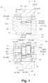
Fig. 1 is a longitudinal sectional view of a speed reducer illustrating one embodiment. -
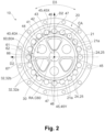
Fig. 2 is a sectional view along the line II-II inFig. 1 . -
Fig. 3 is a plan view of a spacer and external gear that can be included in the speed reducer ofFig. 1 .} -
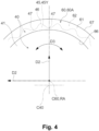
Fig. 4 is a plan view of the spacer and external gear shown inFig. 3 in a different relative position from that shown inFig. 3 . -
Fig. 5 is a view corresponding toFig. 4 and shows one modification example of the spacer and external gear. -
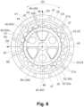
Fig. 6 is a view corresponding toFig. 2 and shows another modification example of the spacer and external gear. -
Fig. 7 is an partially enlarged view ofFig. 1 . -
Fig. 8 is a cross-sectional view similar toFig. 7 , showing yet another modification example of the spacer and external gear. - One embodiment of the invention will be hereinafter described with reference to the attached drawings.
Figs. 1 to 8 are drawings for illustrating one embodiment of the invention. Components and elements shown in some drawings may be omitted in other drawings. Scale and aspect ratio may differ between the drawings. - The overall configuration of a
speed reducer 10 will be now described with reference toFigs. 1 and2 . Thespeed reducer 10 receives rotation from a motor or other drive means. The speed reducer 10 reduces the inputted rotation speed and outputs the rotation at the reduced speed. Thespeed reducer 10 includes acasing 20, acarrier 30, anexternal gear 40, and ashaft 50 as its main components. Thecasing 20 houses thecarrier 30.Main bearings 12 are provided between thecasing 20 and thecarrier 30. Thecasing 20 andcarrier 30 are rotatable relative to each other about a rotation axis RA. Thereduction gear 10 reduces the input rotation and outputs it as relative rotation of thecasing 20 and thecarrier 30. - The direction parallel to the rotation axis RA is referred to as an axial direction D1. A circumferential direction D3, referred to later, is the direction along the circular ring centered on the rotation axis RA, as shown in
Fig. 2 . A radial direction D2 is perpendicular to the rotation axis RA, as shown inFig. 1 . The side closer to the rotation axis RA in the radial direction D2 is referred to as an inner side or inward, and the side away from the rotation axis RA in the radial direction D2 is referred to as an outer side or outward. - The
carrier 30 holds theshaft 50 in a rotatable manner. A shaft rotation axis SRA of theshaft 50 extends parallel to the axial direction D1. The drive means inputs rotation to theshaft 50. Theshaft 50 has an eccentric member 55. The eccentric member 55 is disposed off the center of rotation of theshaft 50. Theshaft 50 penetrates through theexternal gear 40. Theexternal gear 40 is disposed on the eccentric member 55. As theshaft member 50 rotates, theexternal gear 40 oscillates eccentrically. Theexternal gear 40 hasexternal teeth 45 that mesh with internal teeth 25 on an inner surface of thecasing 20. The number of the internal teeth 25 is different from the number of theexternal teeth 45. When rotation is inputted to theshaft 50, theexternal gear 40 oscillates eccentrically as the internal teeth 25 mesh with theexternal teeth 45. Due to the difference in the number of teeth between the internal teeth 25 andexternal teeth 45, theouter gear 40 and thecarrier 30 supporting theshaft member 50 rotate relative to thecasing 20. - The
casing 20,carrier 30,external gear 40, andshaft 50 will now be described, based on the specific configurations shown in the drawings. - The
casing 20 has the internal teeth 25. The internal teeth 25 are arranged in the circumferential direction D3. The circumferential direction D3 is the direction along the circular ring centered on the rotation axis RA. In the illustrated example, thespeed reducer 10 includes twoexternal gears external teeth 45 of the twoexternal gears - The
casing 20 shown in the drawing includes a substantially cylindrical-shapedcasing body 21 and internal tooth pins 24 held on the inner surface of thecasing body 21. As shown inFig. 2 , thecasing body 21 has a plurality ofpin grooves 21a arranged in the circumferential direction D3. Thepin grooves 21a extend in the axial direction D1 and accommodate and hold the cylindrical internal tooth pins 24. Each internal tooth pin 24 constitutes one internal tooth 25. The internal tooth pins 24 each may be rotatable within thepin grooves 21a about a central axis CA (seeFig. 1 ) of the internal tooth pin 24. - The
carrier 30 is accommodated in thecasing 20 via the pair ofmain bearings 12. Thecarrier 30 is rotatable relative to the casing about the rotation axis RA. The illustratedcarrier 30 has a carrier plate 31 andcarrier base 32 fixed to each other. The carrier plate 31 has a plate-shaped first carrier portion 31a. Thecarrier base 32 has a plate-shapedsecond carrier portion 32a and acolumn portion 32b extending from thesecond carrier portion 32a. Thecolumn portion 32b protrudes in the axial direction D1 from thesecond carrier portion 32a toward the first carrier portion 31a. Thesecond carrier portion 32a and thecolumn portion 32b may be integrally formed. Two ormore column portions 32b are arranged at intervals in the circumferential direction D3. In the illustrated example, threecolumn portions 32b are provided. Theexternal gear 40 is disposed between the first carrier portion 31a and thesecond carrier portion 32a in the axial direction D1. - The illustrated
carrier 30 has acentral hole 34 and a throughhole 35. Thecentral hole 34 and throughhole 35 penetrate the carrier plate 31 andcarrier base 32. Thecentral hole 34 is located on the rotation axis RA. Two or more throughholes 35 are provided in thecarrier 30. The two or more throughholes 35 are arranged at intervals in the circumferential direction D3. - The
shaft 50 is rotatably held in thecarrier 30. The illustratedshaft 50 is inserted in the throughhole 35 of thecarrier 30. A pair ofmain shaft bearings 13 are provided between thecarrier 30 and theshaft member 50. Via themain shaft bearings 13, theshaft 50 can rotate relative to thecarrier 30 about the shaft rotation axis SRA. The shaft rotation axis SRA extends parallel to the axial direction D1. Theillustrated speed reducer 10 has the two ormore shafts 50 inserted in the two or more throughholes 35, respectively. The two ormore shafts 50 arranged at the intervals in the circumferential direction D3. In the illustrated example, three throughholes 35 are provided. In the illustrated example, threeshaft members 50 are provided. - The illustrated
shaft 50 includes a shaft body 51 and the pair of eccentric members 55 disposed on the shaft body 51. The eccentric members 55 are cylindrical portions. The eccentric members 55 have diameters larger than that of the shaft body 51. The eccentric members 55 are eccentrically disposed from the shaft rotation axis SRA, which is the center of rotation of theshaft 50. The pair of eccentric members 55 includes a first eccentric member 55A and a second eccentric member 55B. The first eccentric member 55A and the second eccentric member 55B are offset from the shaft rotation axis SRA by the same amount of eccentricity on the opposite sides. In other words, in the section perpendicular to the axial direction D1, the center of the first eccentric member 55A and the center of the second eccentric member 55B are disposed symmetrically with respect to one point on the shaft rotation axis SRA. - The shaft body 51 includes a first
bearing support portion 52a that is inserted in the first carrier portion 31a of the carrier plate 31 and a secondbearing support portion 52b that is inserted in thesecond carrier portion 32a of thecarrier base 32. The bearingsupport portions main shaft bearings 13. The pair of eccentric members 55a and 55b are disposed between the pair of bearingsupport portions shaft 50 further has an input gear 59 fixed to the shaft body 51. In the illustrated example, the firstbearing support portion 52a, the first eccentric member 55a, the second eccentric member 55b, the secondbearing support portion 52b, and the input gear 59 are arranged in this order from a first side (right side inFig. 1 ) to a second side (left side inFig. 1 ) in the axial direction D1. - The
illustrated speed reducer 10 has a firstexternal gear 40A and a secondexternal gear 40B as the external gears 40. The firstexternal gear 40A is disposed on the first eccentric members 55A of the two ormore shafts 50. The secondexternal gear 40B is disposed on the second eccentric members 55B of the two ormore shafts 50. The firstexternal gear 40A and the secondexternal gear 40B are disposed between the first carrier portion 31a of the carrier plate 31 and thesecond carrier portion 32a of thecarrier base 32 in the axial direction D1. The firstexternal gear 40A is disposed between the first carrier portion 31a and the secondexternal gear 40B in the axial direction D1. The secondexternal gear 40B is disposed between the firstexternal gear 40A and thesecond carrier portion 32a in the axial direction D1. - The illustrated
external gear 40 includes a disk-shapedcentral plate portion 41 andexternal teeth 45 arranged along the periphery of thecentral plate 41. Thecentral plate portion 41 has acentral hole 42 and a column throughhole 43. Thecentral hole 42 is situated on the rotation axis RA. Thecentral hole 42 faces thecentral hole 34 in the axial direction D1. In the illustrated example, two or more column throughholes 43 are arranged at intervals in the circumferential direction D3. Thecolumn portions 32b of thecarrier 30 are inserted through the column through holes 43. In the illustrated example, three column throughholes 43 are provided. - The
central plate portion 41 is further provided with two or more shaft through holes 44. In the illustrated embodiment, three shaft throughholes 44 are arranged at intervals in the circumferential direction D3. Each eccentric body 55 is disposed in the corresponding shaft throughhole 44. A bearing 15 is provided between the eccentric member 55 and theexternal gear 40. The firstexternal gear 40A is supported on the first eccentric member 55A of theshaft 50 via a first bearing 15A. The secondexternal gear 40B is supported on the second eccentric member 55B of theshaft 50 via a second bearing 15B. - Each
external gear 40 is supported on the corresponding one of the eccentric members 55. Rotational phases of the eccentric members 55 of the two ormore shafts 50 can be synchronized. Therefore, as theshafts 50 rotate, theexternal gears 40 oscillate eccentrically. In other words, as the two ormore shafts 50 rotate, theexternal gears 40 translate and move along a circumferential path around the rotation axis RA. The firstexternal gear 40A and the secondexternal gear 40B rotate shifted by half a cycle in phase from each other. - Rotation is inputted to the
above speed reducer 10 from a drive means such as a motor. For example, an output gear of the drive means is disposed on the rotation axis RA and meshes with the input gears 59 of the two ormore shafts 50. When the output gear rotates, theshafts 50 rotate and theexternal gears 40 oscillate eccentrically. At this time, theexternal teeth 45 of theexternal gears 40 mesh with the internal teeth 25 of thecasing 20. Due to the difference in the number between theexternal teeth 45 and the internal teeth 25, thecarrier 30, which supports theexternal gears 40 via theshafts 50, and thecasing 20 rotate relatively about the rotation axis RA. When thecasing 20 is fixed, the rotation of thecarrier 30 is outputted. Whereas when thecarrier 30 is fixed, the rotation of thecasing 20 is outputted. - When the
speed reducer 10 operates, theexternal gears 40 oscillate eccentrically between the first carrier portion 31a and thesecond carrier portion 32a of thecarrier 30. The external gears 40 are prevented from moving in the axial direction D1 by contacting thecarrier 30 or themain bearings 12, and are retained on the eccentric members 55. The period of eccentric oscillation of theexternal gears 40 is the same as the rotation period of theshafts 50. Thus, theexternal gears 40 oscillates eccentrically at a high speed. - In conventional eccentric oscillating speed reducers, friction occur between the external gear and carrier due to the movement of the external gear relative to the carrier caused by eccentric oscillation of the external gear. The friction can cause abrasion of the external gears and carrier. As the external gears and carrier wear, the play or gap between the components of the speed reducer increases, making it difficult to precisely output a desired amount of rotation from the speed reducer. It is known that the amount of abrasion of two adjacent components is affected by pressure and relative motion speed between them. As the pressure or relative motion speed increases, the amount of abrasion increases, and furthermore, damage such as seizure may occur. Especially for speed reducers that rotate at high speeds, the relative motion speed increases, and abrasion of components including the external gear is more increased. To reduce the abrasion, it is effective to reduce the relative motion speed. It is also effective to reduce the pressure to reduce the abrasion.
- To address this, the speed reducer of the embodiment includes annular spacers 60 disposed between the
external gears 40 and thecarrier 30. The spacers 60 can rotate while contacting theexternal gears 40 andcarrier 30. With such spacers 60, abrasion of theexternal gears 40 andcarrier 30, as well as abrasion of the spacers 60, can be effectively suppressed. The spacer 60 will now be described based on one specific example and modification example. In the following different configuration examples, corresponding components, members, parts, etc. will be given the same numerals, and those descriptions will be omitted. - The spacer 60 described below is applicable to the above-mentioned
speed reducer 10 described with reference to the specific examples shown inFigs. 1 and2 . The application of the spacer 60 is not limited to the specific examples shown inFigs. 1 and2 . -
Figs. 1 to 6 show one specific example and modification example of thespeed reducer 10 that includes the spacers 60. Thespeed reducer 10 includes thecarrier 30, theshafts 50 rotatably supported by thecarrier 30, and theexternal gears 40 that are supported by theshafts 50 and eccentrically oscillate relative to thecarrier 30 by rotation of theshafts 50. Theillustrated speed reducer 10 includes thecasing 20 having the internal teeth 25 that mesh with theexternal teeth 45 of the external gears 40. Thecasing 20 rotatably supports thecarrier 30. In theillustrated speed reducer 10, the spacers 60 include a first spacer 60A and a second spacer 60B. The first spacer 60A is disposed between the first carrier portion 31a and the firstexternal gear 40A in the axial direction D1. The first spacer 60A is rotatable while contacting the first carrier portion 31a and the firstexternal gear 40A. The second spacer 60B is disposed between thesecond carrier portion 32a and the secondexternal gear 40B in the axial direction D1. The second spacer 60B is rotatable while contacting thesecond carrier portion 32a and the secondexternal gear 40B. - It is known that the amount of abrasion of two adjacent components is affected by pressure or relative motion speed between them. By providing the spacers 60, the relative motion of the
carrier 30 andexternal gears 40 without any spacers 60 can be distributed between the relative motion between theexternal gears 40 and the spacers 60 and the relative motion between the spacers 60 and thecarrier 30. The rotation of the spacers 60 can reduce the relative motion speed of thecarrier 30 with respect to the spacers 60 and the relative motion speed of theexternal gears 40 with respect to the spacers 60, compared to the relative motion speed of thecarrier 30 andexternal gear 40 in the casing where the spacers 60 are not provided. Since the spacer 60 is formed in an annular shape, the contact area of thecarrier 30 and the spacer 60 can be secured. Moreover, the annular shape of the spacer 60 can realize a smooth relative motion of the spacer 60 with respect to thecarrier 30. Thus, it is possible to reduce the pressure between the two adjacent components. - As described above, by providing the spacers 60, the relative motion speed and pressure can be reduced. As a result, the spacers 60 can effectively suppress abrasion of the components of the
speed reducer 10, such as thecarrier 30 and the external gears 40. By suppressing abrasion, it is possible to precisely output the desired amount of rotation from thespeed reducer 10 over a long period of time. The life of thespeed reducer 10 can be extended and the reliability of thespeed reducer 10 can be improved. - In the illustrated example, the spacers 60 include the first spacer 60A and the second spacer 60B. The first spacer 60A disposed between the first carrier portion 31a and the first
external gear 40A in the axial direction D1 rotates while contacting the first carrier portion 31a and the firstexternal gear 40A. This configuration makes it possible to reduce the total amount of abrasion of the first carrier portion 31a, the firstexternal gear 40A and the first spacer 60A when the first spacer 60A is provided, compared to the total amount of abrasion of the first carrier portion 31a and the firstexternal gear 40A when the first spacer 60A is not provided. The second spacer 60B disposed between thesecond carrier portion 32a and the secondexternal gear 40B in the axial direction D1 rotates while contacting thesecond carrier portion 32a and the secondexternal gear 40B. This configuration makes it possible to reduce the total amount of abrasion of thesecond carrier portion 32a, the secondexternal gear 40B and the second spacer 60B when the second spacer 60B is provided, compared to the total amount of abrasion of thesecond carrier portion 32a and the secondexternal gear 40B when the second spacer 60B is not provided. In this way, the abrasion of the first carrier portion 31a, the first spacer 60A, the firstexternal gear 40A, the secondexternal gear 40B, the second spacer 60B, and thesecond carrier portion 32a can be reduced. - The
speed reducer 10 ofFig. 1 includes an annular intermediate spacer 60C disposed between the firstexternal gear 40A and secondexternal gear 40B. The intermediate spacer 60C can rotate while contacting the firstexternal gear 40A and the secondexternal gear 40B. The intermediate spacer 60C can function in the same manner as the first spacer 60A and the second spacer 60B. In other words, the total amount of abrasion of the firstexternal gear 40A, the intermediate spacer 60C, and the secondexternal gear 40B when the intermediate spacer 60C is provided can be made smaller than the total amount of abrasion of the firstexternal gear 40A and the secondexternal gear 40B when the intermediate spacer 60C is not provided. In this way, the abrasion of the firstexternal gear 40A, the intermediate spacer 60C, and the secondexternal gear 40B can be reduced. - When referring to as the "spacer 60" without distinguishing between the first spacer 60A, second spacer 60B, and intermediate spacer 60C, the description regarding the "spacer 60" can be applied to any of first spacer 60A, second spacer 60B, and intermediate spacer 60C. Similarly, the description regarding the "
external gear 40" can be applied to both the firstexternal gear 40A and the secondexternal gear 40B. The description of the "eccentric member 55" is applicable to both the first eccentric member 55A and the second eccentric member 55B. The description of the "bearing 15" is applicable to both the first bearing 15A and the second bearing 15B. - As can be clearly seen in
Fig. 2 , the spacer 60 can rotate while contacting the internal teeth 25 from the inner side in the radial direction. By contacting the internal teeth 25 of thecasing 20, the spacer 60 is prevented from moving outward in the radial direction D2. The spacers 60 on the internal teeth 25 can rotate smoothly. The spacer 60 can rotate more smoothly on the internal tooth 25 when the internal tooth pin 24, which constitutes the internal tooth 25, is rotatable in thepin groove 21a. Since the spacer 60 is smoothly rotatable, it is possible to more effectively reduce the relative motion speed and pressure between the spacer 60 and the components adjacent to the spacer 60. Therefore it is possible to more effectively reduce abrasion of the components of thespeed reducer 10, such as thecarrier 30, theexternal gears 40, and the spacers 60. - The spacer 60 has an inner
peripheral edge 66 and an outerperipheral edge 67. The center of the outerperipheral edge 67 may be situated on the rotation axis RA. Here, the "center" means the center of gravity of the shape enclosed by the contour of the subject when viewed from the axial direction D1, in other words, in projection onto a plane perpendicular to the axial direction D1. In other words, the center of the outerperipheral edge 67 means the center of gravity of the shape enclosed by the outerperipheral edge 67. As an example, when theouter edge 67 has a circular shape when viewed from the axial direction D1, the center of the outerperipheral edge 67 coincides with the center of the circular shape. According to this configuration, the spacers help uniform application of pressure to the components. Thus, it is possible to more effectively reduce the relative motion speed and pressure between the spacer 60 and the component adjacent to the spacer 60. As a result, abrasion of the spacer 60 and the components adjacent to the spacer 60 can be more effectively reduced. - The spacer 60 may be rotatable about the rotation axis RA. According to this configuration, the spacer 60 can easily rotate with the eccentric oscillation of the
external gear 40. Thus, it is possible to more effectively reduce the relative motion speed and pressure between the spacer 60 and the components adjacent to the spacer 60. As a result, abrasion of the spacer 60 and the components adjacent to the spacer 60 can be more effectively reduced. - In the illustrated example, the spacer 60 has an annular shape. The spacer 60 is formed in a plate shape and has a
first surface 61 and asecond surface 62 that can surface contact adjacent components. As shown inFig. 2 , the innerperipheral edge 66 is circular. The outerperipheral edge 67 is also circular. The center of the innerperipheral edge 66 and the center of the outerperipheral edge 67 may coincide. In other words, the inner and outerperipheral edge peripheral edge 67 may internally contact the internal teeth 25 of thecasing 20. That is, the outerperipheral edge 67 may have the same diameter as the circle contacting the internal teeth 25 of thecasing 20 on the inner side. Alternatively, the outerperipheral edge 67 may have a diameter that is slightly smaller than the diameter of the circle contacting the internal teeth 25 of thecasing 20 on the inner side. In such an example, the center of the outerperipheral edge 67 of the spacer 60 may be situated on the rotation axis RA. The spacer 60 is rotatable about the rotation axis RA. As a result, abrasion of the spacer 60 and components adjacent to the spacer 60 can be more effectively reduced. - As shown in
Fig. 2 , the annular spacer 60 may contact the eccentrically oscillatingexternal gear 40 in an annular area. In this example, a larger contact area can be secured between the spacer 60 and theexternal gear 40. It is also possible to stably hold the spacer 60 in an orientation orthogonal to the axial direction D1. Thus, it is possible to more effectively reduce the relative motion speed and pressure between the spacer 60 and the components adjacent to the spacer 60. As a result, abrasion of the spacer 60 and the components adjacent to the spacer 60 can be more effectively reduced. - As shown in
Fig. 2 , theexternal gear 40 disposed eccentrically from the rotation axis RA. In other words, at any given timing, the distance from the rotation axis RA to atip 46 or bottom 47 of eachexternal tooth 45 of theexternal gear 40 is not constant when viewed from the axial direction D1. The distance from the rotation axis RA to thetooth tip 46 or bottom 47 of eachexternal tooth 45 of theexternal gear 40 varies. Whereas the spacer 60 is formed in the annular shape whose center C60 is situated on the rotation axis RA. In this example, in any state, the annular spacer 60 contacts the eccentrically oscillatingexternal gear 40 in the annular region. That is, the annular spacer 60 may always be in contact with the eccentrically oscillatingexternal gear 40 in the annular region. - The
tooth tip 46 refers to the portion of the tooth that is farthest outward in the radial direction from thecentral plate portion 41. Generally, thetooth tip 46 appears at the position corresponding to the center of theexternal tooth 45 in the circumferential direction. The tooth bottom 47 refers to the portion of the tooth that is closest to thecentral plate portion 41 in the radial direction. The tooth bottom 47 is the portion that is closest to the two circumferentially adjacent external teeth. - The first spacer 60A and the second spacer 60B may contact the
carrier 30 in the annular region. With this configuration, a large contact area between thecarrier 30 and the first and second spacers 60A, 60B can be secured. It is also possible to stably hold the first spacer 60A and the second spacer 60B in an orientation orthogonal to the axial direction D1. Thus, the pressure between thecarrier 30 and the first and second spacers 60A, 60B, and abrasion of the first spacer 60A, the second spacer 60B, and thecarrier 30 can be more effectively suppressed. - When the first spacer 60A and the second spacer 60B rotate about the rotation axis RA relative to the
carrier 30, as in the illustrated example, the annular first spacer 60A and the annular second spacer 60B can contact a certain area of thecarrier 30. In other words, at any given time, the first spacer 60A and the second spacer 60B can contact thecarrier 30 in the annular region. - The
external gear 40 oscillates eccentrically. Therefore, eachexternal tooth 45 of theexternal gear 40 changes its position relative to the spacer 60.Figs 3 to 5 illustrate the positional relationship between the spacer 60 and theexternal gear 40 in the radial direction D2.Figs. 3 to 5 show the spacer 60 and theexternal gear 40 observed from the axial direction D1.Fig. 3 shows, together with the spacer 60, an external tooth 45X, which is moved to the outermost position in the radial direction D2 by the eccentric oscillation of theexternal gear 40.Figs. 4 and5 show, together with the spacer 60, an external tooth 45Y, which is moved to the innermost position in the radial direction D2 by the eccentric oscillation of theexternal gear 40. In the examples shown inFigs. 3 to 5 , the spacer 60 is formed in the annular shape. The center C60 of the spacer 60 coincides with the center of the innerperipheral edge 66 and the center of the outerperipheral edge 67. The center C60 of the spacer 60 is situated on the rotation axis RA.Figs. 3 to 5 also show a center C40 of theexternal gear 40. The center C40 of theexternal gear 40 coincides with the center of gravity of thecentral plate portion 41, which is disk-shaped. - In the example of
Fig. 3 , when thetooth tip 46 of the external tooth 45X has moved to the outermost position in the radial direction D2, the tip is situated on the outer side of the outerperipheral edge 67 of the spacer 60 in the radial direction D2. In the example ofFig. 4 , when thetooth tip 46 of the external tooth 45Y has moved to the innermost position in the radial direction D2, the tip is situated on the inner side of the outerperipheral edge 67 of the spacer 60 in the radial direction D2. In this example, thetips 46 of theexternal teeth 45 included in theexternal gear 40 can move beyond the outerperipheral edge 67 of the spacer 60 by the eccentric oscillation of theexternal gear 40. In this example, as shown inFig. 2 , some of thetooth tips 46 of theexternal teeth 45 are situated on the outer side of the outerperipheral edge 67 of the spacer 60 in the radial direction D2, and the remainingtooth tips 46 of theexternal teeth 45 are situated on the inner side of the outerperipheral edge 67 of the spacer 60 in the radial direction D2. - The following advantageous effects can be expected when the
tooth tips 46 of theexternal teeth 45 included in theexternal gear 40 move across the outerperipheral edge 67 of the spacer 60 as theexternal gear 40 oscillates eccentrically. - First, as shown in
Fig. 4 , when sometooth tips 46 of theexternal teeth 45 are situated on the inner side of the outerperipheral edge 67 in the radial direction D2, thesurfaces 61, 62 (in the example ofFig. 4 , the second surface 62) facing theexternal gear 40 of the spacer 60 are at least partially uncovered by theexternal gear 40 and exposed. This enhances supply of lubricant to thesurfaces 61, 62 (in the example ofFig. 4 , the second surface 62) of the spacer 60 facing theexternal gear 40, thereby effectively suppressing abrasion of the spacer 60 and theexternal gear 40. - The rotation of the spacer 60 relative to the
external gear 40 is promoted by the spacer 60 contacting and being rubbed against the outer peripheral edge of theexternal gear 40, which includes thetooth tips 46 of theexternal teeth 45. The motion speed of theexternal gear 40 in the circumferential direction D3 is the largest at its outermost circumferential edge in the radial direction D2, and the circumferential length of theexternal gear 40 in the circumferential direction D3 is the longest at its outermost circumferential edge in the radial direction D2. Therefore, by providing the spacer 60, a high relative motion speed between theexternal gear 40 and thecarrier 30 can be distributed. In addition, the pressure can be reduced by increasing the contact area between the spacer 60 and theexternal gear 40 andcarrier 30. Thus, it is possible to reduce the pressure and relative motion speed. - As a result of the above, the relative motion speed and pressure between the spacer 60 and the
external gear 40 adjacent to the spacer 60 can be reduced, and abrasion of the spacer 60 andexternal gear 40 can be more effectively reduced. - As shown in
Figs. 4 and2 , thetooth tips 46 of all theexternal teeth 45 of theexternal gear 40 may be situated on the outer side of the innerperipheral edge 66 of the spacer 60 in the radial direction D2. In this example, a larger contact area can be secured between the spacer 60 and theexternal gear 40. It is also possible to stably hold the spacer 60 in an orientation orthogonal to the axial direction D1. Thus, it is possible to more effectively reduce the relative motion speed and pressure between the spacer 60 and the components adjacent to the spacer 60. In this way, abrasion of the spacer 60 and components adjacent to the spacer 60 can be more effectively reduced. - Furthermore, as shown in
Fig. 4 , thetooth bottom 47 of the external gear 45Y, which has moved to the innermost position in the radial direction D2, may be situated on the outer side of the innerperipheral edge 66 of the spacer 60 in the radial direction D2. In this example, the spacer 60 and theexternal gear 40 contact each other in the annular region, and a large contact area between the spacer 60 and theexternal gear 40 can be secured. It is also possible to stably hold the spacer 60 in the orientation orthogonal to the axial direction D1. Thus, it is possible to more effectively reduce the pressure between the spacer 60 and the components adjacent to the spacer 60. As a result, abrasion of the spacer 60 and components adjacent to the spacer 60 can be more effectively reduced. - Unlike the example shown in
Fig. 4 , thetooth bottom 47 of the external tooth 45Y, which has moved to the innermost possible position in the radial direction D2, may be situated on the inner side of the innerperipheral edge 66 of the spacer 60 in the radial direction D2 as shown inFig. 5 . In the example ofFig. 3 , when thetooth bottom 47 of the external tooth 45Y has moved to the outermost possible position in the radial direction D2, the tooth bottom is situated on the outer side of the innerperipheral edge 66 of the spacer 60 in the radial direction D2. In the examples ofFigs. 3 and5 , thetooth bottoms 47 of theexternal teeth 45 included in theexternal gear 40 can move beyond the innerperipheral edge 66 of the spacer 60 by the eccentric oscillation of theexternal gear 40. In these examples, some of thetooth bottoms 47 of theexternal teeth 45 are situated on the outer side of the outerperipheral edge 66 of the spacer 60 in the radial direction D2, and the remainingtooth bottoms 47 of theexternal teeth 45 are situated on the outer side of the innerperipheral edge 66 of the spacer 60 in the radial direction D2. - The following advantageous effects can be expected when the
tooth bottoms 47 of theexternal teeth 45 included in theexternal gear 40 move across the innerperipheral edge 66 of the spacer 60 as theexternal gear 40 oscillates eccentrically. - First, when some
tooth bottoms 47 of theexternal tooth 45 are situated on the inner side of the innerperipheral edge 66 in the radial direction D2, thesurfaces 61, 62 (in the example ofFig. 5 , the second surface 62) facing theexternal gear 40 of the spacer 60 are at least partially uncovered by theexternal gear 40 and exposed. This enhances supply of lubricant to thesurfaces 61, 62 (in the example ofFig. 5 , the second surface 62) of the spacer 60 facing theexternal gear 40, thereby effectively suppressing abrasion of the spacer 60 and theexternal gear 40. - As a result, the relative motion speed and pressure between the spacer 60 and the
external gear 40 adjacent to the spacer 60 can be reduced, and abrasion of the spacer 60,external gear 40, andcarrier 30 can be more effectively reduced. - As described above, the
external gear 40 is provided with the column throughhole 43 through which thecolumn portion 32b of thecarrier 30 passes. In the example ofFig. 2 , the column throughholes 43 are situated on the inner side of the outerperipheral edge 66 of the spacer 60 in the radial direction D2. In this example, a larger contact area can be secured between the spacer 60 and theexternal gear 40. As a result, the relative motion speed and pressure between the spacer 60 and theexternal gear 40 adjacent to the spacer 60 can be reduced, and abrasion of the spacer 60 andexternal gear 40 can be more effectively reduced. - In the example of
Fig. 2 , the innerperipheral edge 66 of the spacer 60 is always situated on the outer side from the outermost position of the column throughhole 43 in the radial direction D2. According to this example, contact between the spacer 60 and thecolumn portion 32b can be reliably avoided. However, unlike the example ofFig. 2 , the outermost position of the column throughhole 43 in the radial direction D2 may move beyond the innerperipheral edge 66 of the spacer 60 due to the eccentric oscillation of theexternal gear 40, as shown inFig. 6 . In this example, thesurfaces 61, 62 (in the example ofFig. 6 , the second surface 62) of the spacer 60 facing theexternal gear 40 are exposed in the column throughhole 43 as theexternal gear 40 oscillates eccentrically. This enhances supply of lubricant to thesurfaces 61, 62 (in the example ofFig. 6 , the second surface 62) of the spacer 60 facing theexternal gear 40, thereby effectively suppressing abrasion of the spacer 60 and theexternal gear 40. - The
column portions 32b of thecarrier 30 pass through the column throughholes 43 of theexternal gear 40. In the example ofFig. 6 , thecolumn portions 32b are situated on the inner side of the innerperipheral edge 66 of the spacer 60 in the radial direction D2. This avoids contact between thecolumn portions 32b and the spacer 60. In the illustrated example, the spacer 60 is centered on the rotation axis RA, while movement of the spacer 60 in the radial direction D2 is restricted by contacting the internal teeth 25 of thecasing 20. Therefore, thecarrier 30 havingcolumn portions 32b and the spacer 60 substantially do not move relative to each other in the radial direction D2. Therefore, contact between thecolumn portions 32b and the spacer 60 can be reliably avoided. - In the
speed reducer 10 ofFig. 1 , theexternal gear 40 includes the firstexternal gear 40A and secondexternal gear 40B. The firstexternal gear 40A and secondexternal gear 40B are disposed in the axial direction D1. Thespeed reducer 10 includes the annular spacers 60A, 60B disposed between thecarrier 30 and theexternal gears 40, and the intermediate spacer 60C disposed between the firstexternal gear 40A and the secondexternal gear 40B. - The spacer 60 does not move largely relative to the
carrier 30 in the radial direction D2. Theexternal gear 40 moves relative to thecarrier 30 and spacer 60 in the axial direction D1. Therefore, as shown inFigs. 7 and8 , the contact area between thecarrier 30 and the spacers 60A, 60B can be relatively increased. The contact area between thecarrier 30 and the spacers 60 is relatively small. As shown inFigs. 7 and8 , the contact area between thecarrier 30 and the spacers 60 is smallest in the region where the phase difference in the eccentric oscillation of the firstexternal gear 40A and the secondexternal gear 40B is large (typically, 180 degrees out of phase). - As shown in
Figs. 7 and8 , the spacers 60A, 60B can contact thecarrier 30 from one side in the axial direction D1 with a relatively large contact area. The spacers 60A, 60B can be stably supported by thecarrier 30 from one side in the axial direction D1. Therefore, the spacers 60A, 60B can stably maintain their posture even when thrust forces (forces in the axial direction D1) from theexternal gears 40 are applied to some areas of the spacers. - On the other hand, as shown in
Figs. 7 and8 , the contact area between the intermediate spacer 60C and the firstexternal gear 40A and the contact area between the intermediate spacer 60C and the secondexternal gear 40B may shift in the radial direction D2. Moreover, the contact area between the intermediate spacer 60C and theexternal gears external gear 40. In particular, the intermediate spacer 60C can be locally deformed in the region where the phases of the eccentric oscillation of the first and secondexternal gears - In terms of suppressing deformation of the intermediate spacer 60C, it is effective to increase the thickness TC of the intermediate spacer 60C. As shown in
Figs. 7 and8 , the thickness TC of the intermediate spacer 60C may be greater than or equal to the thickness TA of the first spacer 60A, and the thickness TC of the intermediate spacer 60C may be greater than or equal to the thickness TB of the second spacer 60B. As shown inFig. 8 , the thickness TC of the intermediate spacer 60C may be greater than the thickness TA of the first spacer 60A and the thickness TC of the intermediate spacer 60C may be greater than the thickness TB of the second spacer 60B. The thickness of the spacer 60 is herein defined as the length along the axial direction D1 of the spacer 60. - By increasing the thickness TC of the intermediate spacer 60C as described above, deformation of the intermediate spacer 60C can be prevented. This allows the intermediate spacer 60C and the
external gear 40 to be kept in surface contact each other, and the contact area between the intermediate spacer 60C and theexternal gear 40 can be secured. In addition, the posture of the intermediate spacer 60C can be maintained more stably such that the intermediate spacer 60C extends on a plane orthogonal to the axial direction D1. This configuration can suppress abrasion of the intermediate spacer 60C. - Furthermore, by increasing the thickness TC of the intermediate spacer 60C, the following advantageous effects can also be obtained. By increasing the thickness TC of the intermediate spacer 60C, deformation of the intermediate spacer 60C can be suppressed, as described above. By suppressing the deformation of the intermediate spacer 60C, the generation of abnormal noise caused by local contact between the intermediate spacer 60C and the
external gear 40 can be suppressed. - In the one embodiment described above, the
speed reducer 10 includes thecarrier 30, theshaft 50 rotatably supported by thecarrier 30, theexternal gear 40 supported by theshafts 50 and eccentrically oscillating with respect to thecarrier 30 by rotation of theshaft 50, and the annular spacer 60 situated between theexternal gear 40 andcarrier 30. The spacer 60 rotates while contacting theexternal gear 40 andcarrier 30. With the spacer 60, the relative motion of thecarrier 30 and theexternal gear 40 can be distributed between the relative motion of theexternal gear 40 and thecarrier 30 and the relative motion of thecarrier 30 and the spacer 60. This reduces the relative motion speed between the two adjacent components, effectively suppressing abrasion of the components of thespeed reducer 10, such as thecarrier 30 and theexternal gear 40. - While the embodiment has been described with reference to the specific and modification examples, these examples are not intended to limit the embodiment. The foregoing embodiment can be implemented in various other specific forms and is susceptible to omission, replacement, and modification of various elements thereof within the purport of the invention.
- For example, we have shown the example in which the object of application of the spacer 60 is the speed reducer having the two or
more shafts 50, but the application is not limited to this example. The spacer 60 may be applied to a speed reducer having only oneshaft 50 disposed on the rotation axis RA. - In the embodiments disclosed herein, a member formed of multiple components may be integrated into a single component, or conversely, a member formed of a single component may be divided into multiple components. Irrespective of whether or not the components are integrated, they are acceptable as long as they are configured to attain the object of the invention.
-
- 10 speed reducer
- 15 bearing
- 20 casing
- 30 carrier
- 31a first carrier portion
- 32a second carrier portion
- 40, 40A, 40B, 40C external gear
- 50 shaft
- 55 eccentric member
- 60 spacer
- 61, 62 surfaces
- 66 inner peripheral edge
- 67 outer peripheral edge
Claims (15)
- A speed reducer (10) comprising:a carrier (30);a shaft (50) rotatably supported by the carrier (30);an external gear (40, 40A, 40B) supported by the shaft (50), the external gear (40, 40A, 40B) eccentrically oscillating with respect to the carrier (30) by rotation of the shaft (50); andan annular spacer (60, 60A, 60B) disposed between the external gear (40, 40A, 40B) and the carrier (30), the spacer (60, 60A, 60B) rotating while contacting the external gear (40, 40A, 40B) and the carrier (30).
- The speed reducer (10) of claim 1, further comprising a casing (20) having internal teeth (25) that mesh with external teeth (45) of the eccentrically oscillating external gear (40, 40A, 40B),
wherein the spacer (60, 60A, 60B) rotates while contacting the internal teeth (25) from an inner side in a radial direction (D2). - The speed reducer (10) of claim 1 or 2, wherein the spacer (60, 60A, 60B) contacts the external gear (40, 40A, 40B) in an annular region.
- The speed reducer (10) of any one of claims 1 to 3, wherein tooth tips (46) of external teeth (45) included in the external gear (40, 40A, 40B) move beyond an outer peripheral edge (67) of the spacer (60, 60A, 60B) by eccentric oscillation of the external gear (40, 40A, 40B).
- The speed reducer (10) of any one of claims 1 to 4, wherein tooth tips (46) of all external teeth (45) included in the external gear (40, 40A, 40B) are situated on an outer side of an inner peripheral edge (66) of the spacer (60, 60A, 60B) in a radial direction (D2).
- The speed reducer (10) of any one of claims 1 to 5, wherein tooth bottoms (47) of all external teeth (45) included in the external gear (40, 40A, 40B) are situated on an outer side of an inner peripheral edge (66) of the spacer 60 in a radial direction (D2).
- The speed reducer (10) of any one of claims 1 to 6, wherein tooth tips (47) of external teeth (45) included in the external gear (40, 40A, 40B) move beyond an inner peripheral edge (66) of the spacer (60, 60A, 60B) by eccentric oscillation of the external gear (40, 40A, 40B).
- The speed reducer (10) of any one of claims 1 to 7, wherein the external gear (40, 40A, 40B) is provided with a column through hole (43) through which a column portion (32b) of the carrier (30) passes, and
wherein an outermost position of the column through hole (43) in a radial direction (D2) move beyond an inner peripheral edge (66) of the spacer (60, 60A, 60B) by eccentric oscillation of the external gear (40, 40A, 40B). - The speed reducer (10) of any one of claims 1 to 8, wherein the external gear (40, 40A, 40B) is provided with a column through hole (43) through which a column portion (32b) of the carrier (30) passes, and
wherein an inner peripheral edge (66) of the spacer (60, 60A, 60B) is always situated on an outer side from an outermost position of the column through hole (43) in a radial direction (D2). - The speed reducer (10) of any one of claims 1 to 9, wherein the spacer (60, 60A, 60B) contacts the carrier (30) in an annular region.
- The speed reducer (10) of any one of claims 1 to 10, further comprising a casing (20) having internal teeth (25) that mesh with external teeth (45) of the eccentrically oscillating external gear (40, 40A, 40B), the casing (20) rotatably supporting the carrier (30),
wherein a center (C60) of an outer peripheral edge (67) of the spacer (60, 60A, 60B) is situated on an axis (RA) of relative rotation between the carrier (30) and the casing (20). - The speed reducer (10) of any one of claims 1 to 11, wherein a casing (20) having internal teeth (25) that mesh with external teeth (45) of the eccentrically oscillating external gear (40, 40A, 40B), the casing (20) rotatably supporting the carrier (30), and
wherein the spacer (60, 60A, 60B) is rotatable about an axis (RA) of relative rotation between the carrier (30) and the casing (20). - The speed reducer (10) of any one of claims 1 to 12, wherein the external gear external gear (40, 40A, 40B) includes a first external gear (40A) and a second external gear (40B),wherein an intermediate spacer (60C) is provided between the first external gear (40A) and the second external gear (40B), andwherein a thickness (TB) of the intermediate spacer (60C) is greater than or equal to a thickness (TA, TB) of the annular spacer (60A, 60B).
- The speed reducer (10) of any one of claims 1 to 13, wherein the carrier (30) has a first carrier portion (31a) and a second carrier portion (31b) arranged in an axial direction,wherein the external gear (40) includes a first external gear (40a) and a second external gear (40b) disposed between the first carrier portion (31a) and the second carrier portion (31b) in the axial direction, andwherein the spacer (60) includes a first spacer (60A) disposed between the first carrier portion (31a) and the first external gear (40A) and a second spacer (60B) disposed between the second external gear (40B) and the second carrier portion (31b).
- The speed reducer (10) of claim 14, further comprising an annular intermediate spacer (60C) disposed between the first external gear (40A) and the second external gear (40B), the intermediate spacer (60C) rotating while contacting the first external gear (40A) and the second external gear (40B).
Applications Claiming Priority (2)
| Application Number | Priority Date | Filing Date | Title |
|---|---|---|---|
| JP2023014530 | 2023-02-02 | ||
| JP2023212235A JP2024110394A (en) | 2023-02-02 | 2023-12-15 | Gearbox |
Publications (2)
| Publication Number | Publication Date |
|---|---|
| EP4411170A1 true EP4411170A1 (en) | 2024-08-07 |
| EP4411170B1 EP4411170B1 (en) | 2026-04-15 |
Family
ID=89722999
Family Applications (1)
| Application Number | Title | Priority Date | Filing Date |
|---|---|---|---|
| EP24153926.1A Active EP4411170B1 (en) | 2023-02-02 | 2024-01-25 | Speed reducer |
Country Status (1)
| Country | Link |
|---|---|
| EP (1) | EP4411170B1 (en) |
Citations (5)
| Publication number | Priority date | Publication date | Assignee | Title |
|---|---|---|---|---|
| WO1995022017A1 (en) * | 1994-02-14 | 1995-08-17 | Spinea S.R.O. | Gear |
| DE102014005435A1 (en) * | 2013-04-15 | 2014-10-16 | Nabtesco Corporation | Exzenteroszillationsgetriebevorrichtung |
| DE112013003373T5 (en) * | 2012-07-03 | 2015-03-19 | Nabtesco Corporation | Eccentric vibration gear device |
| EP4067697A1 (en) * | 2021-03-31 | 2022-10-05 | Nabtesco Corporation | Drive transmission device and construction machine |
| DE102022115297A1 (en) * | 2021-07-14 | 2023-01-19 | Sumitomo Heavy Industries, Ltd. | ECCENTRIC OSCILLATING GEAR DEVICE |
-
2024
- 2024-01-25 EP EP24153926.1A patent/EP4411170B1/en active Active
Patent Citations (5)
| Publication number | Priority date | Publication date | Assignee | Title |
|---|---|---|---|---|
| WO1995022017A1 (en) * | 1994-02-14 | 1995-08-17 | Spinea S.R.O. | Gear |
| DE112013003373T5 (en) * | 2012-07-03 | 2015-03-19 | Nabtesco Corporation | Eccentric vibration gear device |
| DE102014005435A1 (en) * | 2013-04-15 | 2014-10-16 | Nabtesco Corporation | Exzenteroszillationsgetriebevorrichtung |
| EP4067697A1 (en) * | 2021-03-31 | 2022-10-05 | Nabtesco Corporation | Drive transmission device and construction machine |
| DE102022115297A1 (en) * | 2021-07-14 | 2023-01-19 | Sumitomo Heavy Industries, Ltd. | ECCENTRIC OSCILLATING GEAR DEVICE |
Also Published As
| Publication number | Publication date |
|---|---|
| EP4411170B1 (en) | 2026-04-15 |
Similar Documents
| Publication | Publication Date | Title |
|---|---|---|
| KR101890007B1 (en) | Gear unit | |
| US8047943B2 (en) | Reduction gear transmission | |
| TWI614427B (en) | Flexing meshing gear device | |
| CN103649587B (en) | gear unit | |
| JP2010156430A (en) | Deceleration device | |
| JP2017044319A (en) | Eccentric oscillation type gear device and industrial robot | |
| KR101044071B1 (en) | Reduction Gear Using Needle Roller Bearing | |
| JP4608252B2 (en) | Eccentric oscillating gear unit | |
| CN106402282A (en) | Eccentric oscillating gear device and method for manufacturing same | |
| EP4411170B1 (en) | Speed reducer | |
| KR20220125780A (en) | Gear device and method of manufacturing gear device | |
| JP2015127563A (en) | Cylindrical roller bearing | |
| JP2024110394A (en) | Gearbox | |
| CN118423440A (en) | reducer | |
| JP6992141B2 (en) | Gear device | |
| JP2020070856A (en) | Bearing and speed reducer | |
| JP2013122300A (en) | Rotating portion structure and method of assembling the same | |
| EP4421337A1 (en) | Bearing, speed reducer, and robot | |
| CN111720497B (en) | Cycloidal speed reducer, method for manufacturing cycloidal speed reducer, and motor unit | |
| US20250305560A1 (en) | Eccentric oscillating gear device | |
| US10955007B2 (en) | Bearing retaining mechanism | |
| JP2024166662A (en) | Gearing | |
| JP7624847B2 (en) | Transmission device | |
| US11313439B2 (en) | Speed reducer | |
| JP7058357B2 (en) | Gear device |
Legal Events
| Date | Code | Title | Description |
|---|---|---|---|
| PUAI | Public reference made under article 153(3) epc to a published international application that has entered the european phase |
Free format text: ORIGINAL CODE: 0009012 |
|
| STAA | Information on the status of an ep patent application or granted ep patent |
Free format text: STATUS: REQUEST FOR EXAMINATION WAS MADE |
|
| 17P | Request for examination filed |
Effective date: 20240125 |
|
| AK | Designated contracting states |
Kind code of ref document: A1 Designated state(s): AL AT BE BG CH CY CZ DE DK EE ES FI FR GB GR HR HU IE IS IT LI LT LU LV MC ME MK MT NL NO PL PT RO RS SE SI SK SM TR |
|
| GRAP | Despatch of communication of intention to grant a patent |
Free format text: ORIGINAL CODE: EPIDOSNIGR1 |
|
| STAA | Information on the status of an ep patent application or granted ep patent |
Free format text: STATUS: GRANT OF PATENT IS INTENDED |
|
| INTG | Intention to grant announced |
Effective date: 20251208 |
|
| P01 | Opt-out of the competence of the unified patent court (upc) registered |
Free format text: CASE NUMBER: UPC_APP_0003087_4411170/2026 Effective date: 20260128 |
|
| GRAS | Grant fee paid |
Free format text: ORIGINAL CODE: EPIDOSNIGR3 |
|
| GRAA | (expected) grant |
Free format text: ORIGINAL CODE: 0009210 |
|
| STAA | Information on the status of an ep patent application or granted ep patent |
Free format text: STATUS: THE PATENT HAS BEEN GRANTED |
|
| AK | Designated contracting states |
Kind code of ref document: B1 Designated state(s): AL AT BE BG CH CY CZ DE DK EE ES FI FR GB GR HR HU IE IS IT LI LT LU LV MC ME MK MT NL NO PL PT RO RS SE SI SK SM TR |
|
| REG | Reference to a national code |
Ref country code: CH Ref legal event code: F10 Free format text: ST27 STATUS EVENT CODE: U-0-0-F10-F00 (AS PROVIDED BY THE NATIONAL OFFICE) Effective date: 20260415 |
|
| REG | Reference to a national code |
Ref country code: DE Ref legal event code: R096 Ref document number: 602024003885 Country of ref document: DE |