EP4411124A1 - Exhaust duct for gas turbine engine - Google Patents
Exhaust duct for gas turbine engine Download PDFInfo
- Publication number
- EP4411124A1 EP4411124A1 EP24153704.2A EP24153704A EP4411124A1 EP 4411124 A1 EP4411124 A1 EP 4411124A1 EP 24153704 A EP24153704 A EP 24153704A EP 4411124 A1 EP4411124 A1 EP 4411124A1
- Authority
- EP
- European Patent Office
- Prior art keywords
- exhaust duct
- central axis
- outlet conduits
- outlet
- inlet
- Prior art date
- Legal status (The legal status is an assumption and is not a legal conclusion. Google has not performed a legal analysis and makes no representation as to the accuracy of the status listed.)
- Pending
Links
Images


Classifications
-
- F—MECHANICAL ENGINEERING; LIGHTING; HEATING; WEAPONS; BLASTING
- F02—COMBUSTION ENGINES; HOT-GAS OR COMBUSTION-PRODUCT ENGINE PLANTS
- F02K—JET-PROPULSION PLANTS
- F02K1/00—Plants characterised by the form or arrangement of the jet pipe or nozzle; Jet pipes or nozzles peculiar thereto
- F02K1/40—Nozzles having means for dividing the jet into a plurality of partial jets or having an elongated cross-section outlet
-
- F—MECHANICAL ENGINEERING; LIGHTING; HEATING; WEAPONS; BLASTING
- F02—COMBUSTION ENGINES; HOT-GAS OR COMBUSTION-PRODUCT ENGINE PLANTS
- F02C—GAS-TURBINE PLANTS; AIR INTAKES FOR JET-PROPULSION PLANTS; CONTROLLING FUEL SUPPLY IN AIR-BREATHING JET-PROPULSION PLANTS
- F02C6/00—Plural gas-turbine plants; Combinations of gas-turbine plants with other apparatus; Adaptations of gas-turbine plants for special use
- F02C6/20—Adaptations of gas-turbine plants for driving vehicles
- F02C6/206—Adaptations of gas-turbine plants for driving vehicles the vehicles being airscrew driven
-
- F—MECHANICAL ENGINEERING; LIGHTING; HEATING; WEAPONS; BLASTING
- F05—INDEXING SCHEMES RELATING TO ENGINES OR PUMPS IN VARIOUS SUBCLASSES OF CLASSES F01-F04
- F05D—INDEXING SCHEME FOR ASPECTS RELATING TO NON-POSITIVE-DISPLACEMENT MACHINES OR ENGINES, GAS-TURBINES OR JET-PROPULSION PLANTS
- F05D2220/00—Application
- F05D2220/30—Application in turbines
- F05D2220/32—Application in turbines in gas turbines
- F05D2220/323—Application in turbines in gas turbines for aircraft propulsion, e.g. jet engines
-
- F—MECHANICAL ENGINEERING; LIGHTING; HEATING; WEAPONS; BLASTING
- F05—INDEXING SCHEMES RELATING TO ENGINES OR PUMPS IN VARIOUS SUBCLASSES OF CLASSES F01-F04
- F05D—INDEXING SCHEME FOR ASPECTS RELATING TO NON-POSITIVE-DISPLACEMENT MACHINES OR ENGINES, GAS-TURBINES OR JET-PROPULSION PLANTS
- F05D2250/00—Geometry
- F05D2250/10—Two-dimensional
- F05D2250/14—Two-dimensional elliptical
-
- F—MECHANICAL ENGINEERING; LIGHTING; HEATING; WEAPONS; BLASTING
- F05—INDEXING SCHEMES RELATING TO ENGINES OR PUMPS IN VARIOUS SUBCLASSES OF CLASSES F01-F04
- F05D—INDEXING SCHEME FOR ASPECTS RELATING TO NON-POSITIVE-DISPLACEMENT MACHINES OR ENGINES, GAS-TURBINES OR JET-PROPULSION PLANTS
- F05D2250/00—Geometry
- F05D2250/50—Inlet or outlet
- F05D2250/51—Inlet
-
- F—MECHANICAL ENGINEERING; LIGHTING; HEATING; WEAPONS; BLASTING
- F05—INDEXING SCHEMES RELATING TO ENGINES OR PUMPS IN VARIOUS SUBCLASSES OF CLASSES F01-F04
- F05D—INDEXING SCHEME FOR ASPECTS RELATING TO NON-POSITIVE-DISPLACEMENT MACHINES OR ENGINES, GAS-TURBINES OR JET-PROPULSION PLANTS
- F05D2250/00—Geometry
- F05D2250/50—Inlet or outlet
- F05D2250/52—Outlet
-
- F—MECHANICAL ENGINEERING; LIGHTING; HEATING; WEAPONS; BLASTING
- F05—INDEXING SCHEMES RELATING TO ENGINES OR PUMPS IN VARIOUS SUBCLASSES OF CLASSES F01-F04
- F05D—INDEXING SCHEME FOR ASPECTS RELATING TO NON-POSITIVE-DISPLACEMENT MACHINES OR ENGINES, GAS-TURBINES OR JET-PROPULSION PLANTS
- F05D2250/00—Geometry
- F05D2250/70—Shape
- F05D2250/71—Shape curved
-
- F—MECHANICAL ENGINEERING; LIGHTING; HEATING; WEAPONS; BLASTING
- F05—INDEXING SCHEMES RELATING TO ENGINES OR PUMPS IN VARIOUS SUBCLASSES OF CLASSES F01-F04
- F05D—INDEXING SCHEME FOR ASPECTS RELATING TO NON-POSITIVE-DISPLACEMENT MACHINES OR ENGINES, GAS-TURBINES OR JET-PROPULSION PLANTS
- F05D2250/00—Geometry
- F05D2250/70—Shape
- F05D2250/73—Shape asymmetric
Definitions
- Exemplary embodiments pertain to the art of gas turbine engines, and more particularly to exhaust ducts of gas turbine engines.
- exhaust ducts are disposed downstream of a turbine section to evacuate combustion products utilized to drive a turbine of the turbine section.
- the flow of gases entering the exhaust ducts may be swirling and have a substantial velocity, which may be used as a residual thrust to the engine. Swirling of the gases may produce total pressure loss, which in turn may reduce the residual thrust available.
- the exhaust exit duct exit has a circular shape to keep manufacturing process simple for exhaust and for ease of mating of a stub duct installed by an aircraft manufacturer at the exit of the exhaust duct to direct flow and to control the area for a specific design condition.
- an exhaust duct of an aircraft engine that includes an annular inlet conduit having an inlet central axis, and at least two outlet conduits in flow communication with the inlet conduit.
- the at least two outlet conduits are located non-parallel to the inlet central axis.
- Each of the at least two outlet conduits include an outlet port defining a distal end of each of the two outlet conduits. At least one of the outlet ports is non-circular in cross-sectional shape.
- the at least one outlet port is elliptical in cross-sectional shape.
- a major axis of the elliptical cross-sectional shape extends in a direction perpendicular to the inlet central axis.
- a major axis of the elliptical cross-sectional shape extends in a direction along the inlet central axis direction.
- an aspect ratio of the major axis to a minor axis of the elliptical cross-sectional shape is between 1 and 2.
- each of the outlet conduits extend curvilinearly from an intersection of the outlet conduits and the inlet conduit.
- a cross-sectional area of the outlet conduits varies between the outlet port and an intersection of the outlet conduits and the inlet conduit.
- the inlet conduit includes a central bore to accommodate a shaft of the gas turbine engine therein.
- the at least two outlet conduits are two outlet conduits located 180 degrees apart relative to the inlet central axis.
- a propulsion system of an aircraft that includes a gas turbine engine having a combustor to combust a mixture of fuel and air and a turbine driven by a flow of combustion gases about an engine central axis.
- the propulsion system further includes an exhaust nozzle to receive combustion gases from the turbine and exhaust the combustion gases.
- the exhaust nozzle includes an annular inlet conduit extending along the engine central axis, and at least two outlet conduits in flow communication with the inlet conduit.
- the at least two outlet conduits are located non-parallel to the engine central axis.
- Each of the at least two outlet conduits include an outlet port defining a distal end of each of the two outlet conduits. At least one of the outlet ports is non-circular in cross-sectional shape.
- the at least one outlet port is elliptical in cross-sectional shape.
- a major axis of the elliptical cross-sectional shape extends in a direction perpendicular to the engine central axis.
- a major axis of the elliptical cross-sectional shape extends in a direction along the engine central axis direction.
- an aspect ratio of the major axis to a minor axis of the elliptical cross-sectional shape is between 1 and 2.
- each of the outlet conduits extend curvilinearly from an intersection of the outlet conduits and the inlet conduit.
- the inlet conduit includes a central bore to accommodate a shaft of the gas turbine engine therein.
- the shaft drives a propeller of the aircraft.
- the exhaust duct is located between the propeller and the turbine, relative to the engine central axis.
- the at least two outlet conduits are two outlet conduits located 180 degrees apart relative to the engine central axis.
- FIG. 1 illustrates an embodiment of a gas turbine engine 10, in this example a turboprop engine, of a type provided for use in subsonic flight, generally comprising serial flow communication along an engine central axis 12, parallel to the X-axis of the orthogonal axes illustrated in FIG. 1 .
- the gas turbine engine 10 includes a propeller 14 through which ambient air is propelled, a compressor section 16 that receives an airflow 18 through an airflow inlet 20, and a combustor 22 in which the compressed airflow is mixed with a flow of fuel and combusted.
- the operation of the combustor 22 produces a stream of combustion gases 24, which flow through a turbine section 26, which includes one or more turbines, one of which may be a compressor-drive turbine 28 and another which may be a propeller-drive turbine 30.
- the exhaust duct 38 in this embodiment a dual exhaust port 40 exhaust duct is formed by a generally Y-shaped body 42.
- the body 42 is annular and defines a fluid flow passage about a central bore 44, which accommodates the propeller shaft 34 therethrough.
- the fluid flow passage of the body 42 generally includes an inlet conduit 46 through which the central bore 44 extends, and in this example, two outlet conduits 48, 50 branching off from the inlet conduit 46.
- the inlet conduit 46 and the outlet conduits 48, 50 may adopt various configurations. For example, they can take the form of cylindrically straight or curved conduits.
- the body 42 may include more than two outlet conduits 48, 50.
- the inlet conduit 46 may be provided in the form annular inlet conduit 70 where the inlet conduit 46 and the outlet conduits 48, 50 connect and communicate.
- the inlet conduit 46 has a circular cross-section and is coaxial with the engine central axis 12.
- the outlet conduits 48, 50 are positioned perpendicularly to the inlet conduit 46, extending radially relative to the inlet conduit 46 and defining a substantially T-shaped body 42.
- the outlet conduits 48, 50 are positioned non-perpendicularly to the inlet conduit 46, extending both radially and axially relative to the inlet conduit 46 and defining a substantially Y-shaped body 42.
- the outlet conduits 48, 50 each include an outlet port 40 through which the exhaust gases 36 are expelled from the exhaust duct 38.
- the outlet ports 40 are openings defined in an exit plane 52 of each of the outlet conduits 48, 50.
- the exit plane 52 is the distal end of each of the outlet conduits 48, 50.
- At least one of the outlet ports 40 has a non-circular cross-section in the exit plane 52.
- the non-circular cross-section is elliptical, but other non-circular cross-sections are contemplated within the scope of the present disclosure, such as oval, rounded polygonal or the like. As shown in FIG.
- the non-circular shape has a major axis 54 and a minor axis 56, such that the aspect ratio of the major axis 54 to the minor axis 56 is greater than 1. In some embodiments the aspect ratio as greater than 1.5 or 2.
- the area and the shape of the elliptical cross-section is selected to provide a selected exhaust performance while fitting the exhaust duct 38 into a desired volumetric envelope, including satisfying requirements for length of the exhaust duct 38 along the engine central axis 12 and height of the exhaust duct 38 in a direction perpendicular to the engine central axis 12.
- the outlet ports 40 are elliptical, with the major axis 54 of the elliptical shape perpendicular to the engine central axis 12. This reduces an overall duct length 58 of the exhaust duct 38 in a direction parallel to the engine central axis 12, when compared to an outlet duct having a circular outlet port of equal area.
- the major axis 54 is located parallel to the engine central axis 12. While in the embodiments illustrated herein the major axis 54 is located either perpendicular to or parallel to the engine central axis 12, in other embodiments the major axis 54 may have an orientation that is neither perpendicular to nor parallel to the engine central axis 12.
- the improved compactness of the exhaust ducts 38 due to the non-circular outlet conducts 48, 50 allows for the exhaust duct 38 to be packaged into a space having a smaller axial length and/or a reduced height, thus saving space within a nacelle or airframe for other components.
- the outlet conduits 48, 50 are a constant non-circular cross-section along their entire length from their intersection with the inlet conduit 46 to the exit plane 52 of the outlet port 40.
- the cross-sectional shape of the outlet conduits 48, 50 may vary.
- the outlet conduits 48, 50 may have a circular cross-section at their intersection with the inlet conduit 46 and may transition to the elliptical or other non-circular cross-sectional shape at the outlet plane 52.
- the outlet conduits 48, 50 extend along a linear central axis, such that the outlet conduits 48, 50 are "straight". In other embodiments, such as illustrated herein, the outlet conduits 48, 50 follow a curvilinear path along their length from their intersection with the inlet conduit 46 to the outlet plane 52.
- the exhaust ducts 38 described and illustrated herein allow for fitting the exhaust ducts 38 and their outlet ports 40 into tight volumetric envelopes while still achieving a desired cross-sectional area of the outlet ports 40 to achieve a desired performance of the exhaust duct 38.
Landscapes
- Engineering & Computer Science (AREA)
- Chemical & Material Sciences (AREA)
- Combustion & Propulsion (AREA)
- Mechanical Engineering (AREA)
- General Engineering & Computer Science (AREA)
- Exhaust Silencers (AREA)
Abstract
An exhaust duct (38) of an aircraft engine includes an annular inlet conduit (46, 70) having an inlet central axis (12), and at least two outlet conduits (48, 50) in flow communication with the inlet conduit (46, 70). The at least two outlet conduits (48, 50) are located non-parallel to the inlet central axis (12). Each of the at least two outlet conduits (48, 50) include an outlet port (40) defining a distal end of each of the two outlet conduits (48, 50). At least one of the outlet ports (40) is non-circular in crosssectional shape.
Description
- Exemplary embodiments pertain to the art of gas turbine engines, and more particularly to exhaust ducts of gas turbine engines.
- In gas turbine engines, exhaust ducts are disposed downstream of a turbine section to evacuate combustion products utilized to drive a turbine of the turbine section. The flow of gases entering the exhaust ducts may be swirling and have a substantial velocity, which may be used as a residual thrust to the engine. Swirling of the gases may produce total pressure loss, which in turn may reduce the residual thrust available. Typically, the exhaust exit duct exit has a circular shape to keep manufacturing process simple for exhaust and for ease of mating of a stub duct installed by an aircraft manufacturer at the exit of the exhaust duct to direct flow and to control the area for a specific design condition.
- In one aspect, there is provided an exhaust duct of an aircraft engine that includes an annular inlet conduit having an inlet central axis, and at least two outlet conduits in flow communication with the inlet conduit. The at least two outlet conduits are located non-parallel to the inlet central axis. Each of the at least two outlet conduits include an outlet port defining a distal end of each of the two outlet conduits. At least one of the outlet ports is non-circular in cross-sectional shape.
- Additionally or alternatively, in this or other arrangements the at least one outlet port is elliptical in cross-sectional shape.
- Additionally or alternatively, in this or other arrangements a major axis of the elliptical cross-sectional shape extends in a direction perpendicular to the inlet central axis.
- Additionally or alternatively, in this or other arrangements a major axis of the elliptical cross-sectional shape extends in a direction along the inlet central axis direction.
- Additionally or alternatively, in this or other arrangements an aspect ratio of the major axis to a minor axis of the elliptical cross-sectional shape is between 1 and 2.
- Additionally or alternatively, in this or other arrangements each of the outlet conduits extend curvilinearly from an intersection of the outlet conduits and the inlet conduit.
- Additionally or alternatively, in this or other arrangements a cross-sectional area of the outlet conduits varies between the outlet port and an intersection of the outlet conduits and the inlet conduit.
- Additionally or alternatively, in this or other arrangements the inlet conduit includes a central bore to accommodate a shaft of the gas turbine engine therein.
- Additionally or alternatively, in this or other arrangements the at least two outlet conduits are two outlet conduits located 180 degrees apart relative to the inlet central axis.
- There is also provided a propulsion system of an aircraft that includes a gas turbine engine having a combustor to combust a mixture of fuel and air and a turbine driven by a flow of combustion gases about an engine central axis. The propulsion system further includes an exhaust nozzle to receive combustion gases from the turbine and exhaust the combustion gases. The exhaust nozzle includes an annular inlet conduit extending along the engine central axis, and at least two outlet conduits in flow communication with the inlet conduit. The at least two outlet conduits are located non-parallel to the engine central axis. Each of the at least two outlet conduits include an outlet port defining a distal end of each of the two outlet conduits. At least one of the outlet ports is non-circular in cross-sectional shape.
- Additionally or alternatively, in this or other arrangements the at least one outlet port is elliptical in cross-sectional shape.
- Additionally or alternatively, in this or other arrangements a major axis of the elliptical cross-sectional shape extends in a direction perpendicular to the engine central axis.
- Additionally or alternatively, in this or other arrangements a major axis of the elliptical cross-sectional shape extends in a direction along the engine central axis direction.
- Additionally or alternatively, in this or other arrangements an aspect ratio of the major axis to a minor axis of the elliptical cross-sectional shape is between 1 and 2.
- Additionally or alternatively, in this or other arrangements each of the outlet conduits extend curvilinearly from an intersection of the outlet conduits and the inlet conduit.
- Additionally or alternatively, in this or other arrangements wherein a cross-sectional area of the outlet conduits varies between the outlet port and an intersection of the outlet conduits and the inlet conduit.
- Additionally or alternatively, in this or other arrangements the inlet conduit includes a central bore to accommodate a shaft of the gas turbine engine therein.
- Additionally or alternatively, in this or other arrangements the shaft drives a propeller of the aircraft.
- Additionally or alternatively, in this or other arrangements the exhaust duct is located between the propeller and the turbine, relative to the engine central axis.
- Additionally or alternatively, in this or other arrangements the at least two outlet conduits are two outlet conduits located 180 degrees apart relative to the engine central axis.
- The following descriptions should not be considered limiting in any way. With reference to the accompanying drawings, like elements are numbered alike:
-
FIG. 1 is a schematic cross-sectional illustration of an embodiment of a gas turbine engine; -
FIG. 2 is a perspective view of an embodiment of an outlet duct; -
FIG. 3 is a plan view of an embodiment of an outlet duct; -
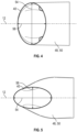
FIG. 4 is an end view of an embodiment of an outlet port of an outlet duct; and -
FIG. 5 is an end view of another embodiment of an outlet port of an outlet duct. - A detailed description of one or more embodiments of the disclosed apparatus and method are presented herein by way of exemplification and not limitation with reference to the Figures.
-
FIG. 1 illustrates an embodiment of agas turbine engine 10, in this example a turboprop engine, of a type provided for use in subsonic flight, generally comprising serial flow communication along an enginecentral axis 12, parallel to the X-axis of the orthogonal axes illustrated inFIG. 1 . Thegas turbine engine 10 includes apropeller 14 through which ambient air is propelled, acompressor section 16 that receives anairflow 18 through anairflow inlet 20, and a combustor 22 in which the compressed airflow is mixed with a flow of fuel and combusted. The operation of the combustor 22 produces a stream ofcombustion gases 24, which flow through aturbine section 26, which includes one or more turbines, one of which may be a compressor-drive turbine 28 and another which may be a propeller-drive turbine 30. - The compressor-
drive turbine 28 is operably connected to thecompressor 16 via acompressor shaft 32 located at the enginecentral axis 12 to rotationally drive thecompressor 16 about the enginecentral axis 12 via rotation of the compressor-drive turbine 28. Similarly, the propeller-drive turbine 30 is operably connected to thepropeller 14 via apropeller shaft 34 located at the enginecentral axis 12 to rotationally drive thepropeller 14 about the enginecentral axis 12, via rotation of the propeller-drive turbine 30. In some embodiments, the compressor-drive turbine 28 is located upstream of the propeller-drive turbine 30 relative to a general direction of flow of thecombustion gases 24 through theturbine section 26.Exhaust gases 36 from theturbine section 26 are expelled from thegas turbine engine 10 via anexhaust duct 38. The direction of flow of theexhaust gases 36 in theexhaust duct 38 are illustrated by arrows IF and EF, indicated incoming flow and outgoing flow, respectively, relative to theexhaust duct 38. - Referring to
FIGs. 2 and 3 , theexhaust duct 38, in this embodiment adual exhaust port 40 exhaust duct is formed by a generally Y-shaped body 42. Thebody 42 is annular and defines a fluid flow passage about acentral bore 44, which accommodates thepropeller shaft 34 therethrough. The fluid flow passage of thebody 42 generally includes aninlet conduit 46 through which thecentral bore 44 extends, and in this example, two outlet conduits 48, 50 branching off from theinlet conduit 46. One skilled in the art will readily appreciate that theinlet conduit 46 and theoutlet conduits body 42 may include more than twooutlet conduits inlet conduit 46 may be provided in the formannular inlet conduit 70 where theinlet conduit 46 and theoutlet conduits inlet conduit 46 has a circular cross-section and is coaxial with the enginecentral axis 12. In some embodiments theoutlet conduits inlet conduit 46, extending radially relative to theinlet conduit 46 and defining a substantially T-shaped body 42. In other embodiments, theoutlet conduits inlet conduit 46, extending both radially and axially relative to theinlet conduit 46 and defining a substantially Y-shaped body 42. - Referring to
FIG. 3 , theoutlet conduits outlet port 40 through which theexhaust gases 36 are expelled from theexhaust duct 38. Theoutlet ports 40 are openings defined in anexit plane 52 of each of theoutlet conduits exit plane 52 is the distal end of each of theoutlet conduits outlet ports 40 has a non-circular cross-section in theexit plane 52. In some embodiments, the non-circular cross-section is elliptical, but other non-circular cross-sections are contemplated within the scope of the present disclosure, such as oval, rounded polygonal or the like. As shown inFIG. 4 , the non-circular shape has amajor axis 54 and aminor axis 56, such that the aspect ratio of themajor axis 54 to theminor axis 56 is greater than 1. In some embodiments the aspect ratio as greater than 1.5 or 2. The area and the shape of the elliptical cross-section is selected to provide a selected exhaust performance while fitting theexhaust duct 38 into a desired volumetric envelope, including satisfying requirements for length of theexhaust duct 38 along the enginecentral axis 12 and height of theexhaust duct 38 in a direction perpendicular to the enginecentral axis 12. - In some embodiments the
outlet ports 40 are elliptical, with themajor axis 54 of the elliptical shape perpendicular to the enginecentral axis 12. This reduces anoverall duct length 58 of theexhaust duct 38 in a direction parallel to the enginecentral axis 12, when compared to an outlet duct having a circular outlet port of equal area. Alternatively, in other embodiments, such as illustrated inFIG. 5 , themajor axis 54 is located parallel to the enginecentral axis 12. While in the embodiments illustrated herein themajor axis 54 is located either perpendicular to or parallel to the enginecentral axis 12, in other embodiments themajor axis 54 may have an orientation that is neither perpendicular to nor parallel to the enginecentral axis 12. The improved compactness of theexhaust ducts 38 due to the non-circular outlet conducts 48, 50 allows for theexhaust duct 38 to be packaged into a space having a smaller axial length and/or a reduced height, thus saving space within a nacelle or airframe for other components. - In some embodiments, the
outlet conduits inlet conduit 46 to theexit plane 52 of theoutlet port 40. In other embodiments, however, the cross-sectional shape of theoutlet conduits outlet conduits inlet conduit 46 and may transition to the elliptical or other non-circular cross-sectional shape at theoutlet plane 52. Further, in some embodiments theoutlet conduits outlet conduits outlet conduits inlet conduit 46 to theoutlet plane 52. - The
exhaust ducts 38 described and illustrated herein allow for fitting theexhaust ducts 38 and theiroutlet ports 40 into tight volumetric envelopes while still achieving a desired cross-sectional area of theoutlet ports 40 to achieve a desired performance of theexhaust duct 38. - The term "about" is intended to include the degree of error associated with measurement of the particular quantity based upon the equipment available at the time of filing the application.
- The terminology used herein is for the purpose of describing particular embodiments only and is not intended to be limiting of the present disclosure. As used herein, the singular forms "a", "an" and "the" are intended to include the plural forms as well, unless the context clearly indicates otherwise. It will be further understood that the terms "comprises" and/or "comprising," when used in this specification, specify the presence of stated features, integers, steps, operations, elements, and/or components, but do not preclude the presence or addition of one or more other features, integers, steps, operations, element components, and/or groups thereof.
- While the present disclosure has been described with reference to an exemplary embodiment or embodiments, it will be understood by those skilled in the art that various changes may be made and equivalents may be substituted for elements thereof without departing from the scope of the present disclosure. In addition, many modifications may be made to adapt a particular situation or material to the teachings of the present disclosure without departing from the essential scope thereof. Therefore, it is intended that the present disclosure not be limited to the particular embodiment disclosed as the best mode contemplated for carrying out this present disclosure, but that the present disclosure will include all embodiments falling within the scope of the claims.
Claims (12)
- An exhaust duct (38) of an aircraft engine (10), comprising:an annular inlet conduit (46, 70) having an inlet central axis (12); andat least two outlet conduits (48, 50) in flow communication with the inlet conduit (46), the at least two outlet conduits (48, 50) located non-parallel to the inlet central axis (12);wherein each of the at least two outlet conduits (48, 50) include an outlet port (40) defining a distal end of each of the two outlet conduits (48, 50); andwherein at least one of the outlet ports (40) is non-circular in cross-sectional shape.
- The exhaust duct of claim 1, wherein at least one of the outlet ports (40) is elliptical in cross-sectional shape.
- The exhaust duct of claim 2, wherein a major axis (54) of the elliptical cross-sectional shape extends in a direction perpendicular to the inlet central axis (12).
- The exhaust duct of claim 2, wherein a major axis (54) of the elliptical cross-sectional shape extends in a direction along the inlet central axis direction (12).
- The exhaust duct of claim 4, wherein an aspect ratio of the major axis (54) to a minor axis (56) of the elliptical cross-sectional shape is between 1 and 2.
- The exhaust duct of any preceding claim, wherein each of the outlet conduits (48, 50) extend curvilinearly from an intersection of the outlet conduits (48, 50) and the inlet conduit (46, 70).
- The exhaust duct of any preceding claim, wherein a cross-sectional area of the outlet conduits (48, 50) varies between the outlet port (40) and an intersection of the outlet conduits (48, 50) and the inlet conduit (46, 70).
- The exhaust duct of any preceding claim, wherein the inlet conduit (46, 70) includes a central bore (44) to accommodate a shaft (34) of the gas turbine engine (10) therein.
- The exhaust duct of any preceding claim, wherein the at least two outlet conduits (48, 50) are two outlet conduits (48, 50) located 180 degrees apart relative to the inlet central axis (12).
- A propulsion system of an aircraft, comprising:
a gas turbine engine (10), including:a combustor (22) to combust a mixture of fuel and air (18); anda turbine (28; 30) driven by a flow of combustion gases (24) about an engine central axis (12); andan exhaust nozzle to receive combustion gases (36) from the turbine (28; 30) and exhaust the combustion gases (36); the exhaust nozzle including the exhaust duct (38) of any preceding claim, wherein the inlet central axis (12) is an engine central axis (12). - The propulsion system of claim 10 as dependent on claim 8, directly or indirectly, wherein the shaft (34) drives a propeller (14) of the aircraft.
- The propulsion system of claim 11, wherein the exhaust duct (38) is located between the propeller (14) and the turbine (28; 30), relative to the engine central axis (12).
Applications Claiming Priority (1)
| Application Number | Priority Date | Filing Date | Title |
|---|---|---|---|
| US18/162,269 US11952962B1 (en) | 2023-01-31 | 2023-01-31 | Exhaust duct for gas turbine engine |
Publications (1)
| Publication Number | Publication Date |
|---|---|
| EP4411124A1 true EP4411124A1 (en) | 2024-08-07 |
Family
ID=89715903
Family Applications (1)
| Application Number | Title | Priority Date | Filing Date |
|---|---|---|---|
| EP24153704.2A Pending EP4411124A1 (en) | 2023-01-31 | 2024-01-24 | Exhaust duct for gas turbine engine |
Country Status (3)
| Country | Link |
|---|---|
| US (2) | US11952962B1 (en) |
| EP (1) | EP4411124A1 (en) |
| CA (1) | CA3223713A1 (en) |
Families Citing this family (2)
| Publication number | Priority date | Publication date | Assignee | Title |
|---|---|---|---|---|
| US12617541B1 (en) | 2024-12-19 | 2026-05-05 | Pratt & Whitney Canada Corp. | Exhaust case for aircraft engine |
| US12529325B1 (en) * | 2025-07-29 | 2026-01-20 | Pratt & Whitney Canada Corp. | Turbine exhaust duct with stiffeners for aircraft engines |
Citations (4)
| Publication number | Priority date | Publication date | Assignee | Title |
|---|---|---|---|---|
| US6371407B1 (en) * | 2000-07-05 | 2002-04-16 | Lockheed Martin Corporation | Mechanism for vectoring exhaust flow |
| US20090001216A1 (en) * | 2007-04-23 | 2009-01-01 | Kirstein Joshua M | Aircraft engine balanced thrust vectoring system |
| US20180328283A1 (en) * | 2017-05-15 | 2018-11-15 | Pratt & Whitney Canada Corp. | Air intake for gas turbine engine |
| US20220260001A1 (en) * | 2021-02-18 | 2022-08-18 | Pratt & Whitney Canada Corp. | Instrumented turbine exhaust duct |
Family Cites Families (23)
| Publication number | Priority date | Publication date | Assignee | Title |
|---|---|---|---|---|
| US2231239A (en) * | 1939-05-16 | 1941-02-11 | Curtiss Wright Corp | Cowling exhaust outlet |
| US3428257A (en) * | 1966-06-03 | 1969-02-18 | Curtiss Wright Corp | Thrust vectoring exhaust nozzle with flow guide for minimizing separation of the jet stream |
| US3981448A (en) * | 1970-04-23 | 1976-09-21 | The Garrett Corporation | Cooled infrared suppressor |
| US4312480A (en) * | 1979-11-26 | 1982-01-26 | Hughes Helicopters, Inc. | Radiation shielding and gas diffusion apparatus |
| US6290173B1 (en) * | 1999-10-28 | 2001-09-18 | Commuter Air Technology, Inc. | Aircraft cracked stack prevention apparatus and method |
| US20060027679A1 (en) * | 2004-08-03 | 2006-02-09 | Mr. Jack Gratteau | Ejector Nozzle |
| FR2900387B1 (en) * | 2006-04-28 | 2009-01-16 | Snecma Sa | EXHAUST ASSEMBLY OF PROPULSION GASES IN AN AIRCRAFT WITH TWO ELBOW ELEMENTS |
| DE07873413T1 (en) * | 2006-06-09 | 2009-07-30 | Bell Helicopter Textron, Inc., Fort Worth | ENGINE EXHAUST SYSTEM WITH DIRECTIONAL NOZZLE |
| US20100199626A1 (en) * | 2008-12-31 | 2010-08-12 | Benjamin Roland Harding | Turbine engine exhaust gas tube mixer |
| US8398359B2 (en) * | 2010-02-17 | 2013-03-19 | General Electric Company | Exhaust diffuser |
| US9969500B2 (en) * | 2014-02-06 | 2018-05-15 | Honeywell International Inc. | Bifurcated ducts including plenums for stabilizing flow therethrough and exhaust systems including the same |
| DE102014011606B4 (en) | 2014-08-04 | 2024-06-20 | Rolls-Royce Solutions GmbH | Exhaust system for an internal combustion engine |
| EP3043056B1 (en) * | 2014-12-17 | 2019-07-31 | Pratt & Whitney Canada Corp. | Exhaust duct for a gas turbine engine |
| US10267191B2 (en) * | 2015-08-07 | 2019-04-23 | Pratt & Whitney Canada Corp. | Turboprop engine assembly with combined engine and cooling exhaust |
| EP3296523A1 (en) | 2016-09-20 | 2018-03-21 | Siemens Aktiengesellschaft | Assembly for splititng a mass flow in two partial mass flows |
| EP4592190A3 (en) * | 2017-06-19 | 2025-10-22 | General Electric Company Polska sp. z o.o. | Exhaust assembly with vortex generator |
| EP3418195B1 (en) | 2017-06-21 | 2021-10-20 | General Electric Company Polska sp. z o.o. | Exhaust stub for an aircraft engine assembly |
| US10745142B2 (en) * | 2018-02-19 | 2020-08-18 | Pratt & Whitney Canada Corp. | Aircraft with wheel well between cooling duct outlets |
| FR3081926B1 (en) | 2018-05-30 | 2021-01-15 | Safran Aircraft Engines | MOUTH OF AN AIRCRAFT ENGINE HOT GAS DUCT THROUGH AN ENGINE WALL |
| KR102874401B1 (en) | 2020-01-10 | 2025-10-22 | 한화에어로스페이스 주식회사 | Exhaust duct and exhaust duct assembly and aircraft using the exhaust duct |
| US12006870B2 (en) | 2020-12-10 | 2024-06-11 | General Electric Company | Heat exchanger for an aircraft |
| CN114233513B (en) | 2021-12-08 | 2023-12-01 | 西北工业大学 | A multi-dimensional deflection pea-shaped S-bend nozzle structure |
| US12420941B2 (en) | 2022-12-01 | 2025-09-23 | Pratt & Whitney Canada Corp. | Aircraft engine with exhaust having removable deflector |
-
2023
- 2023-01-31 US US18/162,269 patent/US11952962B1/en active Active
- 2023-12-19 CA CA3223713A patent/CA3223713A1/en active Pending
-
2024
- 2024-01-24 EP EP24153704.2A patent/EP4411124A1/en active Pending
- 2024-03-01 US US18/593,232 patent/US12372044B2/en active Active
Patent Citations (4)
| Publication number | Priority date | Publication date | Assignee | Title |
|---|---|---|---|---|
| US6371407B1 (en) * | 2000-07-05 | 2002-04-16 | Lockheed Martin Corporation | Mechanism for vectoring exhaust flow |
| US20090001216A1 (en) * | 2007-04-23 | 2009-01-01 | Kirstein Joshua M | Aircraft engine balanced thrust vectoring system |
| US20180328283A1 (en) * | 2017-05-15 | 2018-11-15 | Pratt & Whitney Canada Corp. | Air intake for gas turbine engine |
| US20220260001A1 (en) * | 2021-02-18 | 2022-08-18 | Pratt & Whitney Canada Corp. | Instrumented turbine exhaust duct |
Also Published As
| Publication number | Publication date |
|---|---|
| US12372044B2 (en) | 2025-07-29 |
| US11952962B1 (en) | 2024-04-09 |
| US20240254942A1 (en) | 2024-08-01 |
| CA3223713A1 (en) | 2025-04-09 |
Similar Documents
| Publication | Publication Date | Title |
|---|---|---|
| US12372044B2 (en) | Exhaust duct for gas turbine engine | |
| EP1942269B1 (en) | Convertible gas turbine engine | |
| US6216982B1 (en) | Suction device for boundary layer control in an aircraft | |
| JP6625624B2 (en) | Aircraft turbine engine stator | |
| CN109139258A (en) | Gas-turbine unit and its operating method | |
| EP1998027A2 (en) | Gas turbine engine comprising a nacelle compartment plenum for bleed air flow delivery system | |
| US12017751B2 (en) | Inlet for unducted propulsion system | |
| EP2165929A2 (en) | Thrust vectoring system | |
| EP2256327B1 (en) | Noise reducing device, and jet propulsion system | |
| US8246296B2 (en) | Aspirated impeller | |
| US20080057848A1 (en) | Venturi gate valve assembly for an auxiliary power unit | |
| EP2905227A1 (en) | Bifurcated ducts including plenums for stabilizing flow therethrough and exhaust systems including the same | |
| US8591166B2 (en) | Axial compressor vane | |
| CN103032173B (en) | Conformal inlet device for gas-turbine unit | |
| US4821506A (en) | Radial turbine with variable axial nozzle | |
| US11268390B2 (en) | Vortex generators for turbine engine exhaust | |
| EP3561258A1 (en) | Turbocharger with twin-scroll turbine housing, and cross-scroll communication control valve operable to selectively allow or prevent cross-talk between scrolls | |
| US11078870B2 (en) | Method and system for a stowable bell-mouth scoop | |
| US9926883B1 (en) | Gas turbine engine with axial flow fan with twin stream impeller and variable area bypass nozzle | |
| EP1777156A2 (en) | A gas feed assembly | |
| EP3667030B1 (en) | Modular variable vane assembly for a compressor section of a gas turbine engine | |
| CN114607525A (en) | Hydrogen fuel rotary ramjet turbofan engine | |
| US12152492B2 (en) | Sealing system including a seal assembly between components | |
| EP4696878A1 (en) | Gas turbine engine nozzle with variable area | |
| US12005377B2 (en) | Fuel oxygen reduction unit with level control device |
Legal Events
| Date | Code | Title | Description |
|---|---|---|---|
| PUAI | Public reference made under article 153(3) epc to a published international application that has entered the european phase |
Free format text: ORIGINAL CODE: 0009012 |
|
| STAA | Information on the status of an ep patent application or granted ep patent |
Free format text: STATUS: THE APPLICATION HAS BEEN PUBLISHED |
|
| AK | Designated contracting states |
Kind code of ref document: A1 Designated state(s): AL AT BE BG CH CY CZ DE DK EE ES FI FR GB GR HR HU IE IS IT LI LT LU LV MC ME MK MT NL NO PL PT RO RS SE SI SK SM TR |
|
| STAA | Information on the status of an ep patent application or granted ep patent |
Free format text: STATUS: REQUEST FOR EXAMINATION WAS MADE |
|
| 17P | Request for examination filed |
Effective date: 20250204 |