EP4411118A1 - Buffer air method and system for a bearing component of a gas turbine - Google Patents
Buffer air method and system for a bearing component of a gas turbine Download PDFInfo
- Publication number
- EP4411118A1 EP4411118A1 EP23213838.8A EP23213838A EP4411118A1 EP 4411118 A1 EP4411118 A1 EP 4411118A1 EP 23213838 A EP23213838 A EP 23213838A EP 4411118 A1 EP4411118 A1 EP 4411118A1
- Authority
- EP
- European Patent Office
- Prior art keywords
- buffer
- cavity
- air
- turbine engine
- endwall
- Prior art date
- Legal status (The legal status is an assumption and is not a legal conclusion. Google has not performed a legal analysis and makes no representation as to the accuracy of the status listed.)
- Pending
Links
Images




Classifications
-
- F—MECHANICAL ENGINEERING; LIGHTING; HEATING; WEAPONS; BLASTING
- F01—MACHINES OR ENGINES IN GENERAL; ENGINE PLANTS IN GENERAL; STEAM ENGINES
- F01D—NON-POSITIVE DISPLACEMENT MACHINES OR ENGINES, e.g. STEAM TURBINES
- F01D11/00—Preventing or minimising internal leakage of working-fluid, e.g. between stages
- F01D11/02—Preventing or minimising internal leakage of working-fluid, e.g. between stages by non-contact sealings, e.g. of labyrinth type
- F01D11/04—Preventing or minimising internal leakage of working-fluid, e.g. between stages by non-contact sealings, e.g. of labyrinth type using sealing fluid, e.g. steam
-
- F—MECHANICAL ENGINEERING; LIGHTING; HEATING; WEAPONS; BLASTING
- F01—MACHINES OR ENGINES IN GENERAL; ENGINE PLANTS IN GENERAL; STEAM ENGINES
- F01D—NON-POSITIVE DISPLACEMENT MACHINES OR ENGINES, e.g. STEAM TURBINES
- F01D25/00—Component parts, details, or accessories, not provided for in, or of interest apart from, other groups
- F01D25/08—Cooling; Heating; Heat-insulation
- F01D25/12—Cooling
- F01D25/125—Cooling of bearings
-
- F—MECHANICAL ENGINEERING; LIGHTING; HEATING; WEAPONS; BLASTING
- F01—MACHINES OR ENGINES IN GENERAL; ENGINE PLANTS IN GENERAL; STEAM ENGINES
- F01D—NON-POSITIVE DISPLACEMENT MACHINES OR ENGINES, e.g. STEAM TURBINES
- F01D25/00—Component parts, details, or accessories, not provided for in, or of interest apart from, other groups
- F01D25/16—Arrangement of bearings; Supporting or mounting bearings in casings
-
- F—MECHANICAL ENGINEERING; LIGHTING; HEATING; WEAPONS; BLASTING
- F01—MACHINES OR ENGINES IN GENERAL; ENGINE PLANTS IN GENERAL; STEAM ENGINES
- F01D—NON-POSITIVE DISPLACEMENT MACHINES OR ENGINES, e.g. STEAM TURBINES
- F01D25/00—Component parts, details, or accessories, not provided for in, or of interest apart from, other groups
- F01D25/18—Lubricating arrangements
- F01D25/183—Sealing means
-
- F—MECHANICAL ENGINEERING; LIGHTING; HEATING; WEAPONS; BLASTING
- F01—MACHINES OR ENGINES IN GENERAL; ENGINE PLANTS IN GENERAL; STEAM ENGINES
- F01D—NON-POSITIVE DISPLACEMENT MACHINES OR ENGINES, e.g. STEAM TURBINES
- F01D25/00—Component parts, details, or accessories, not provided for in, or of interest apart from, other groups
- F01D25/18—Lubricating arrangements
- F01D25/22—Lubricating arrangements using working-fluid or other gaseous fluid as lubricant
-
- F—MECHANICAL ENGINEERING; LIGHTING; HEATING; WEAPONS; BLASTING
- F02—COMBUSTION ENGINES; HOT-GAS OR COMBUSTION-PRODUCT ENGINE PLANTS
- F02C—GAS-TURBINE PLANTS; AIR INTAKES FOR JET-PROPULSION PLANTS; CONTROLLING FUEL SUPPLY IN AIR-BREATHING JET-PROPULSION PLANTS
- F02C6/00—Plural gas-turbine plants; Combinations of gas-turbine plants with other apparatus; Adaptations of gas-turbine plants for special use
- F02C6/04—Gas-turbine plants providing heated or pressurised working fluid for other apparatus, e.g. without mechanical power output
- F02C6/06—Gas-turbine plants providing heated or pressurised working fluid for other apparatus, e.g. without mechanical power output providing compressed gas
- F02C6/08—Gas-turbine plants providing heated or pressurised working fluid for other apparatus, e.g. without mechanical power output providing compressed gas the gas being bled from the gas-turbine compressor
-
- F—MECHANICAL ENGINEERING; LIGHTING; HEATING; WEAPONS; BLASTING
- F02—COMBUSTION ENGINES; HOT-GAS OR COMBUSTION-PRODUCT ENGINE PLANTS
- F02C—GAS-TURBINE PLANTS; AIR INTAKES FOR JET-PROPULSION PLANTS; CONTROLLING FUEL SUPPLY IN AIR-BREATHING JET-PROPULSION PLANTS
- F02C7/00—Features, components parts, details or accessories, not provided for in, or of interest apart form groups F02C1/00 - F02C6/00; Air intakes for jet-propulsion plants
- F02C7/06—Arrangements of bearings; Lubricating
-
- F—MECHANICAL ENGINEERING; LIGHTING; HEATING; WEAPONS; BLASTING
- F05—INDEXING SCHEMES RELATING TO ENGINES OR PUMPS IN VARIOUS SUBCLASSES OF CLASSES F01-F04
- F05D—INDEXING SCHEME FOR ASPECTS RELATING TO NON-POSITIVE-DISPLACEMENT MACHINES OR ENGINES, GAS-TURBINES OR JET-PROPULSION PLANTS
- F05D2220/00—Application
- F05D2220/30—Application in turbines
- F05D2220/32—Application in turbines in gas turbines
-
- F—MECHANICAL ENGINEERING; LIGHTING; HEATING; WEAPONS; BLASTING
- F05—INDEXING SCHEMES RELATING TO ENGINES OR PUMPS IN VARIOUS SUBCLASSES OF CLASSES F01-F04
- F05D—INDEXING SCHEME FOR ASPECTS RELATING TO NON-POSITIVE-DISPLACEMENT MACHINES OR ENGINES, GAS-TURBINES OR JET-PROPULSION PLANTS
- F05D2240/00—Components
- F05D2240/50—Bearings
-
- F—MECHANICAL ENGINEERING; LIGHTING; HEATING; WEAPONS; BLASTING
- F05—INDEXING SCHEMES RELATING TO ENGINES OR PUMPS IN VARIOUS SUBCLASSES OF CLASSES F01-F04
- F05D—INDEXING SCHEME FOR ASPECTS RELATING TO NON-POSITIVE-DISPLACEMENT MACHINES OR ENGINES, GAS-TURBINES OR JET-PROPULSION PLANTS
- F05D2240/00—Components
- F05D2240/55—Seals
-
- F—MECHANICAL ENGINEERING; LIGHTING; HEATING; WEAPONS; BLASTING
- F05—INDEXING SCHEMES RELATING TO ENGINES OR PUMPS IN VARIOUS SUBCLASSES OF CLASSES F01-F04
- F05D—INDEXING SCHEME FOR ASPECTS RELATING TO NON-POSITIVE-DISPLACEMENT MACHINES OR ENGINES, GAS-TURBINES OR JET-PROPULSION PLANTS
- F05D2260/00—Function
- F05D2260/60—Fluid transfer
-
- F—MECHANICAL ENGINEERING; LIGHTING; HEATING; WEAPONS; BLASTING
- F05—INDEXING SCHEMES RELATING TO ENGINES OR PUMPS IN VARIOUS SUBCLASSES OF CLASSES F01-F04
- F05D—INDEXING SCHEME FOR ASPECTS RELATING TO NON-POSITIVE-DISPLACEMENT MACHINES OR ENGINES, GAS-TURBINES OR JET-PROPULSION PLANTS
- F05D2260/00—Function
- F05D2260/60—Fluid transfer
- F05D2260/605—Venting into the ambient atmosphere or the like
Definitions
- This disclosure relates generally to a turbine engine and, more particularly, to providing buffer air for a bearing compartment.
- a method of operation is provided during which buffer air flows into a buffer cavity in a turbine engine.
- the buffer cavity surrounds a bearing compartment in the turbine engine.
- Leakage air flows across a buffer seal device in the turbine engine.
- the buffer air and the leakage air are combined to provide combined air.
- the combined air is vented to a pressure sink such that: a pressure of the buffer air within the buffer cavity is maintained at or below a maximum buffer air threshold during operation of the turbine engine; and a flowrate of the leakage air across the buffer seal device is maintained at or above a minimum leakage air threshold during the operation of the turbine engine.
- a method of designing is provided during which a maximum buffer air threshold is identified for buffer air within a buffer cavity in a turbine engine.
- the buffer cavity is outboard of a bearing compartment in the turbine engine.
- a minimum leakage air threshold is identified for leakage air across a buffer seal device from a high pressure cavity in the turbine engine to a low pressure cavity in the turbine engine.
- the low pressure cavity is outboard of the buffer cavity.
- the high pressure cavity is outboard of the low pressure cavity.
- the buffer air combines with the leakage air within the low pressure cavity to provide combined air.
- a venting procedure is provided to vent the combined air from the low pressure cavity such that: a pressure of the buffer air within the buffer cavity is maintained at or below the maximum buffer air threshold during operation of the turbine engine; and a flowrate of the leakage air across the buffer seal device is maintained at or above the minimum leakage air threshold during the operation of the turbine engine.
- an assembly for a turbine engine.
- This assembly includes a stationary structure, a vent line, a valve and a control system.
- the stationary structure forms a bearing compartment, a buffer cavity, a low pressure cavity and a high pressure cavity.
- the buffer cavity is outboard of the bearing compartment.
- the low pressure cavity is outboard of the buffer cavity.
- the high pressure cavity is outboard of the low pressure cavity.
- the vent line is fluidly coupled with the low pressure cavity.
- the low pressure cavity is configured to direct leakage air from the high pressure cavity and buffer air from the buffer cavity into the vent line as low pressure air.
- the valve is fluidly coupled with and downstream of the vent line.
- the control system is configured to signal the valve to control venting of the low pressure air from the low pressure cavity through the vent line such that: a pressure of the buffer air within the buffer cavity is maintained at or below a maximum buffer air threshold; and a flowrate of the leakage air across the buffer seal device is maintained at or above a minimum leakage air threshold.
- the valve may be configured as a two-position valve or a variable position valve.
- the combined air may be to be vented using a valve.
- the maximum buffer air threshold may be identified to account for variation in operation of the valve, deterioration of the valve and/or hysteresis of the valve.
- the combined air may be vented to the pressure sink through a valve.
- the valve may be configured as a discrete position valve.
- the valve may be configured as a variable position valve.
- the method may also include controlling operation of the valve using an electronic control system for the turbine engine.
- the method may also include: monitoring an operational parameter of the turbine engine; and controlling operation of the valve based on the operational parameter.
- At least some of the combined air may be vented to the pressure sink throughout the operation of the turbine engine.
- the leakage air may flow across the buffer seal device from a high pressure cavity in the turbine engine to a low pressure cavity in the turbine engine.
- the buffer air may be combined with the leakage air in the low pressure cavity.
- the low pressure cavity may surround the buffer cavity.
- the high pressure cavity may surround the low pressure cavity.
- a low pressure cavity wall in the turbine engine may include a sidewall and an endwall.
- the sidewall may be radially between and may form the low pressure cavity and the high pressure cavity.
- the endwall may project radially inward from the sidewall.
- the endwall may be axially between and may form the low pressure cavity and the high pressure cavity.
- the buffer seal device may seal a gap between the endwall and a rotating structure in the turbine engine.
- the buffer cavity may be radially adjacent the bearing compartment.
- the low pressure cavity may be radially adjacent the buffer cavity.
- the high pressure cavity may be radially adjacent the low pressure cavity.
- the buffer cavity may axially overlap the bearing compartment.
- the low pressure cavity may axially overlap the buffer cavity.
- the high pressure cavity may axially overlap the low pressure cavity.
- a diffuser plenum in the turbine engine may surround the high pressure cavity.
- a combustor in the turbine engine may be disposed within the diffuser plenum.
- the high pressure cavity may be radially inboard of a core flowpath within the turbine engine.
- a bearing compartment wall in the turbine engine may include a sidewall, a first endwall and a second endwall.
- the sidewall may be radially between and may form the bearing compartment and the buffer cavity.
- the first endwall may project radially inward from the sidewall.
- the first endwall may be axially between and may form the bearing compartment and the buffer cavity.
- the second endwall may project radially inward from the sidewall.
- the second endwall may be axially between and may form the bearing compartment and the buffer cavity.
- a bearing compartment wall in the turbine engine may be disposed between and may form the bearing compartment and the buffer cavity.
- Each of a plurality of bearing seal devices in the turbine engine may seal a respective gap between the bearing compartment wall and a rotating structure in the turbine engine.
- the bearing compartment may be disposed axially between the bearing seal devices.
- both the buffer cavity and the bearing compartment may be formed by a stationary structure and a rotating structure in the turbine engine.
- the present disclosure may include any one or more of the individual features disclosed above and/or below alone or in any combination thereof.
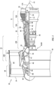
- FIG. 1 is a side cutaway illustration of a gas turbine engine 20.
- This turbine engine 20 extends along an axial centerline 22 between an upstream airflow inlet 24 and a downstream airflow exhaust 26.
- the turbine engine 20 includes a fan section 28, a compressor section 29, a combustor section 30 and a turbine section 31.
- the compressor section 29 includes a low pressure compressor (LPC) section 29A and a high pressure compressor (HPC) section 29B.
- the turbine section 31 includes a high pressure turbine (HPT) section 31A and a low pressure turbine (LPT) section 31B.
- the engine sections 28-31B are arranged sequentially along the axial centerline 22 within an engine housing 34.
- This engine housing 34 includes an inner case 36 (e.g., a core case) and an outer case 38 (e.g., a fan case).
- the inner case 36 may house one or more of the engine sections 29A-31B; e.g., a core of the turbine engine 20.
- the outer case 38 may house at least the fan section 28.
- Each of the engine sections 28, 29A, 29B, 31A and 31B includes a respective bladed rotor 40-44.
- Each of these rotors 40-44 includes a plurality of rotor blades arranged circumferentially around and connected to one or more respective rotor disks.
- the rotor blades may be formed integral with or mechanically fastened, welded, brazed, adhered and/or otherwise attached to the respective rotor disk(s).
- the fan rotor 40 is connected to a geartrain 46, for example, through a fan shaft 48.
- the geartrain 46 and the LPC rotor 41 are connected to and driven by the LPT rotor 44 through a low speed shaft 50.
- At least (or only) the LPC rotor 41, the LPT rotor 44 and the low speed shaft 50 may collectively form a low speed rotating structure 52; e.g., a low speed spool.
- the HPC rotor 42 is connected to and driven by the HPT rotor 43 through a high speed shaft 54.
- At least (or only) the HPC rotor 42, the HPT rotor 43 and the high speed shaft 54 may collectively form a high speed rotating structure 56; e.g., a high speed spool.
- Each of the engine rotating structures 52, 56 and each of the engine shafts 48, 50, 54 is rotatably support by a plurality of bearings 58, some of which are schematically shown in FIG. 1 .
- Each of these bearings 58 is connected to the engine housing 34 by an internal engine structure; e.g., duct walls, support structures (e.g., struts, frames, etc.) and the like.
- At least (or only) the internal engine structure and the engine housing 34 may collectively form a stationary structure 60 of the turbine engine 20.
- This air is directed through the fan section 28 and into a core flowpath 62 and a bypass flowpath 64.
- the core flowpath 62 extends sequentially through the LPC section 29A, the HPC section 29B, the combustor section 30, the HPT section 31A and the LPT section 31B; e.g., the engine core.
- the air within the core flowpath 62 may be referred to as "core air”.
- the bypass flowpath 64 extends through a bypass duct, which bypasses the engine core.
- the air within the bypass flowpath 64 may be referred to as "bypass air”.
- the core air is compressed by the LPC rotor 41 and the HPC rotor 42 and directed into a combustion chamber 66 of a (e.g., annular) combustor 68 in the combustor section 30.
- Fuel is injected into the combustion chamber 66 and mixed with the compressed core air to provide a fuel-air mixture.
- This fuel-air mixture is ignited and combustion products thereof flow through and sequentially cause the HPT rotor 43 and the LPT rotor 44 to rotate.
- the rotation of the HPT rotor 43 and the LPT rotor 44 respectively drive rotation of the HPC rotor 42 and the LPC rotor 41 and, thus, compression of the air received from a core airflow inlet.
- the rotation of the LPT rotor 44 also drives rotation of the fan rotor 40, which fan rotor 40 propels bypass air through and out of the bypass flowpath 64.
- the propulsion of the bypass air may account for a majority of thrust generated by the turbine engine 20, e.g., more than seventy-five percent (75%) of engine thrust.
- the turbine engine 20 of the present disclosure is not limited to the foregoing exemplary thrust ratio.
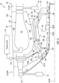
- FIG. 2 illustrates an assembly 70 for the turbine engine 20.
- This engine assembly 70 includes an engine rotating structure 72 (e.g., the high speed rotating structure 56), an engine bearing 74 (e.g., one of the bearings 58), the stationary structure 60, a buffer air system 76 and an air relief system 78.
- the stationary structure 60 of FIG. 2 includes a bearing compartment wall 80, a buffer cavity wall 82, a low pressure (LP) cavity wall 84, a diffuser structure 86 and the combustor 68.
- LP low pressure
- the engine bearing 74 is configured to rotatably couple the engine rotating structure 72 to the stationary structure 60.
- the stationary structure 60 may thereby rotatably support the engine rotating structure 72 through the engine bearing 74.
- Examples of the engine bearing 74 include, but are not limited to, a rolling element bearing and/or a thrust bearing.
- the engine bearing 74 of FIG. 3 includes a bearing inner race 88, a bearing outer race 90 and a plurality of bearing elements 92.
- the inner race 88 is mounted onto the engine rotating structure 72; e.g., onto a shaft 94 (e.g., the high speed shaft 54) of the engine rotating structure 72.
- the outer race 90 circumscribes the inner race 88 and is mounted to a bearing support 96 of the stationary structure 60.
- the bearing elements 92 are distributed circumferentially around a rotational axis 98 (e.g., the axial centerline 22) of the engine rotating structure 72 in a circular array. This array of the bearing elements 92 is disposed radially between and engaged with (e.g., contacts, rolls along, etc.) the inner race 88 and the outer race 90.
- the bearing compartment wall 80 is configured to form a bearing compartment 100 in which the engine bearing 74 is housed.
- the bearing compartment wall 80 of FIG. 3 forms a radial outer peripheral boundary of the bearing compartment 100.
- the bearing compartment wall 80 may also form one or more axial end peripheral boundaries of the bearing compartment 100.
- An inner peripheral boundary of the bearing compartment 100 may be formed by a combination of the bearing compartment wall 80 and the engine rotating structure 72 and its engine shaft 94. In other embodiments, it is contemplated the inner peripheral boundary of the bearing compartment 100 may be (e.g., completely) formed by the engine rotating structure 72 and its engine shaft 94 and/or otherwise formed without the bearing compartment wall 80.
- the bearing compartment 100 may also include a bearing compartment first endwall rim 108 ("first rim”) and/or a bearing compartment second endwall rim 110 ("second rim”).
- the sidewall 102 is disposed at and/or along a radial outer side of the bearing compartment 100.
- the sidewall 102 extends axially along the rotational axis 98 between and to the first endwall 104 and the second endwall 106.
- the sidewall 102 extends circumferentially about (e.g., completely around) the rotational axis 98.
- the sidewall 102 may thereby circumscribe the engine rotating structure 72 and form the radial outer peripheral boundary of the bearing compartment 100.
- FIG. 3 has a non-straight (e.g., curved, bowed, bent, convex, splined, etc.) sectional geometry when viewed, for example, in a reference plane parallel with (e.g., including) the rotational axis 98; e.g., plane of FIG. 3 .
- the present disclosure is not limited to such an exemplary bearing compartment sidewall geometry.
- the first endwall 104 is disposed at and/or along an axial first end of the bearing compartment 100.
- the first endwall 104 is connected to (e.g., formed integral with or attached to) the sidewall 102.
- the first endwall 104 of FIG. 3 projects radially inward (towards the rotational axis 98) from the sidewall 102 to a distal inner end 112 of the first endwall 104, which distal inner end 112 is spaced radially outboard of the engine rotating structure 72 by a gap; e.g., an air gap.
- the first endwall 104 extends circumferentially about (e.g., completely around) the rotational axis 98.
- the first endwall 104 may thereby circumscribe the engine rotating structure 72 and form the first axial end peripheral boundary of the bearing compartment 100.
- the second endwall 106 is disposed at and/or along an axial second end of the bearing compartment 100.
- the second endwall 106 is connected to (e.g., formed integral with or attached to) the sidewall 102.
- the second endwall 106 of FIG. 3 projects radially inward (towards the rotational axis 98) from the sidewall 102 to a distal inner end 114 of the second endwall 106.
- This distal inner end 114 is spaced radially outboard of the engine rotating structure 72 by a gap; e.g., an air gap.
- the second endwall 106 extends circumferentially about (e.g., completely around) the rotational axis 98.
- the second endwall 106 may thereby circumscribe the engine rotating structure 72 and form the second axial end peripheral boundary of the bearing compartment 100.
- the first rim 108 is disposed at and/or along a radial inner side of the bearing compartment 100.
- the first rim 108 is connected to (e.g., formed integral with or attached to) the first endwall 104.
- the first rim 108 of FIG. 3 projects axially out from the first endwall 104, along the rotational axis 98 and the engine rotating structure 72 towards the second endwall 106 and/or the second rim 110, to a distal end 116 of the first rim 108.
- the first rim 108 is spaced radially outboard from the engine rotating structure 72 by a gap; e.g., an air gap.
- the first rim 108 extends circumferentially about (e.g., completely around) the rotational axis 98. The first rim 108 may thereby circumscribe the engine rotating structure 72.
- a bearing compartment first seal device 118 (“first bearing seal device”) is arranged with the bearing compartment wall 80 and its first rim 108 at (e.g., on, adjacent or proximate) the distal end 116 of the first rim 108.
- This first bearing seal device 118 is configured to seal an annular gap between (a) the bearing compartment wall 80 and its first rim 108 and (b) the engine rotating structure 72.
- Examples of the first bearing seal device 118 include, but are not limited to, a face seal device and a carbon seal device.
- the second rim 110 is disposed at and/or along the radial inner side of the bearing compartment 100.
- the second rim 110 is connected to (e.g., formed integral with or attached to) the second endwall 106.
- the second rim 110 of FIG. 3 projects axially out from the second endwall 106, along the rotational axis 98 and the engine rotating structure 72 towards the first endwall 104 and/or the first rim 108, to a distal end 120 of the second rim 110.
- the second rim 110 is spaced radially outboard from the engine rotating structure 72 by a gap; e.g., an air gap.
- the second rim 110 extends circumferentially about (e.g., completely around) the rotational axis 98. The second rim 110 may thereby circumscribe the engine rotating structure 72.
- a bearing compartment second seal device 122 (“second bearing seal device”) is arranged with the bearing compartment wall 80 and its second rim 110 at (e.g., on, adjacent or proximate) the distal end 120 of the second rim 110.
- This second bearing seal device 122 is configured to seal an annular gap between (a) the bearing compartment wall 80 and its second rim 110 and (b) the engine rotating structure 72.
- Examples of the second bearing seal device 122 include, but are not limited to, a face seal device and a carbon seal device.
- the bearing compartment 100 is arranged and extends axially between and to the first endwall 104 and the second endwall 106.
- the bearing compartment 100 is also arranged and extends axially between and to axially the first bearing seal device 118 and the second bearing seal device 122, where the engine bearing 74 is arranged axially between the first bearing seal device 118 and the second bearing seal device 122.
- a first end portion of the bearing compartment 100 is arranged and extends radially between and to the first rim 108 and the sidewall 102.
- a second end portion of the bearing compartment 100 is arranged and extends radially between and to the second rim 110 and the sidewall 102.
- An intermediate portion of the bearing compartment 100 is arranged and extends radially between and to the engine rotating structure 72 and the sidewall 102. This bearing compartment 100 further extends circumferentially about (e.g., completely around) the rotational axis 98. The bearing compartment 100 may thereby circumscribe the engine rotating structure 72 and its engine shaft 94.
- the buffer cavity wall 82 is configured to form a buffer cavity 124.
- the buffer cavity wall 82 of FIG. 3 forms a radial outer peripheral boundary of the buffer cavity 124.
- the buffer cavity wall 82 may also form one or more axial end peripheral boundaries of the buffer cavity 124.
- An inner peripheral boundary of the buffer cavity 124 may be formed by a combination of the bearing compartment wall 80 and the engine rotating structure 72 and its engine shaft 94.
- the buffer cavity wall 82 of FIG. 3 includes a buffer cavity sidewall 126, a buffer cavity first endwall 128 and a buffer cavity second endwall 130.
- the sidewall 126 is disposed at and/or along a radial outer side of the buffer cavity 124.
- the sidewall 126 extends axially along the rotational axis 98 between and to the first endwall 128 and the second endwall 130.
- the sidewall 126 extends circumferentially about (e.g., completely around) the rotational axis 98.
- the sidewall 126 may thereby circumscribe the engine rotating structure 72 and the sidewall 102, and form the radial outer peripheral boundary of the buffer cavity 124.
- the present disclosure is not limited to such an exemplary buffer cavity sidewall geometry.
- the first endwall 128 is disposed at and/or along an axial first end of the buffer cavity 124.
- the first endwall 128 is connected to (e.g., formed integral with or attached to) the sidewall 126.
- the first endwall 128 of FIG. 3 projects radially inward (towards the rotational axis 98) from the sidewall 126 to a distal inner end 132 of the first endwall 128.
- This distal inner end 132 is spaced radially outboard of the engine rotating structure 72, which may provide a (e.g., annular) first control leakage gap 134 radially between the first endwall 128 and the engine rotating structure 72.
- the first endwall 128 extends circumferentially about (e.g., completely around) the rotational axis 98.
- the first endwall 128 may thereby circumscribe the engine rotating structure 72 and form the first axial end peripheral boundary of the buffer cavity 124.
- the second endwall 130 is disposed at and/or along an axial second end of the buffer cavity 124.
- the second endwall 130 is connected to (e.g., formed integral with or attached to) the sidewall 126.
- the second endwall 130 of FIG. 3 projects radially inward (towards the rotational axis 98) from the sidewall 126 to a distal inner end 136 of the second endwall 130.
- This distal inner end 136 is spaced radially outboard of the engine rotating structure 72, which may provide a (e.g., annular) second control leakage gap 138 radially between the second endwall 130 and the engine rotating structure 72.
- the second endwall 130 extends circumferentially about (e.g., completely around) the rotational axis 98.
- the second endwall 130 may thereby circumscribe the engine rotating structure 72 and form the second axial end peripheral boundary of the buffer cavity 124.
- the buffer cavity 124 is arranged axially between the first endwall 128 and the second endwall 130.
- the buffer cavity 124 is arranged radially between the sidewall 126 and the engine rotating structure 72 and its engine shaft 94.
- This buffer cavity 124 further extends circumferentially about (e.g., completely around) the rotational axis 98.
- the buffer cavity 124 may thereby circumscribe the engine rotating structure 72 and its engine shaft 94 as well as the bearing compartment wall 80.
- the buffer cavity 124 of FIG. 3 therefore is (e.g., radially) outboard of and surrounds (in a radial direction and/or an axial direction) the bearing compartment 100.
- an outer portion of the buffer cavity 124 extends radially between and to the sidewall 102 and the sidewall 126.
- a first end portion of the buffer cavity 124 extends axially between and to the first endwall 104 and the first endwall 128.
- a second end portion of the buffer cavity 124 extends axially between and to the second endwall 106 and the second endwall 130.
- a first inner portion of the buffer cavity 124 extends radially between and to the first rim 108 and the engine rotating structure 72 and its engine shaft 94. This first inner portion also extend axially between and to the first bearing seal device 118 and the first endwall 128 and its first control leakage gap 134.
- a second inner portion of the buffer cavity 124 extends radially between and to the second rim 110 and the engine rotating structure 72 and its engine shaft 94. This second inner portion also extend axially between and to the second bearing seal device 122 and the second endwall 130 and its second control leakage gap 138.
- the LP cavity wall 84 is configured to form a low pressure (LP) cavity 140.
- the LP cavity wall 84 of FIG. 3 forms a radial outer peripheral boundary of the LP cavity 140.
- the LP cavity wall 84 may also form one or more axial end peripheral boundaries of the LP cavity 140.
- An inner peripheral boundary of the LP cavity 140 may be formed by a combination of the buffer cavity wall 82 and the engine rotating structure 72 and its engine shaft 94.
- the LP cavity wall 84 of FIG. 3 includes a low pressure (LP) cavity sidewall 142, a low pressure (LP) cavity first endwall 144 and a low pressure (LP) cavity second endwall 146.
- the sidewall 142 is disposed at and/or along a radial outer side of the LP cavity 140.
- the sidewall 142 extends axially along the rotational axis 98 between and to the first endwall 144 and the second endwall 146.
- the sidewall 142 extends circumferentially about (e.g., completely around) the rotational axis 98.
- the sidewall 142 may thereby circumscribe the engine rotating structure 72, the sidewall 126 and the sidewall 102, and form the radial outer peripheral boundary of the LP cavity 140.
- LP cavity sidewall geometry has a non-straight (e.g., curved, bowed, bent, convex, splined, etc.) sectional geometry when viewed, for example, in the reference plane; e.g., the plane of FIG. 3 .
- the present disclosure is not limited to such an exemplary LP cavity sidewall geometry.
- the first endwall 144 is disposed at and/or along an axial first end of the LP cavity 140.
- the first endwall 144 is connected to (e.g., formed integral with or attached to) the sidewall 142.
- the first endwall 144 of FIG. 3 projects radially inward (towards the rotational axis 98) from the sidewall 142 to a distal inner end 148 of the first endwall 144. This distal inner end 148 is spaced radially outboard of the engine rotating structure 72.
- the first endwall 144 extends circumferentially about (e.g., completely around) the rotational axis 98. The first endwall 144 may thereby circumscribe the engine rotating structure 72.
- a first buffer seal device 150 (e.g., a low pressure (LP) cavity seal device) is arranged with the LP cavity wall 84 and its first endwall 144 at (e.g., on, adjacent or proximate) the distal end 148 of the first endwall 144.
- This first buffer seal device 150 is configured to seal an annular gap between (a) the LP cavity wall 84 and its first endwall 144 and (b) the engine rotating structure 72.
- Examples of the first buffer seal device 150 include, but are not limited to, a face seal device, a carbon seal device, a brush seal device, a circumferentially segmented seal device, a KE seal device, a controlled gap seal device and a non-contact seal device.
- Examples of the non-contact seal device include, but are not limited to, a hydrostatic non-contact seal device and a hydrodynamic non-contact seal device.
- the second endwall 146 is disposed at and/or along an axial second end of the LP cavity 140.
- the second endwall 146 is connected to (e.g., formed integral with or attached to) the sidewall 142.
- the second endwall 146 of FIG. 3 projects radially inward (towards the rotational axis 98) from the sidewall 142 to a distal inner end 152 of the second endwall 146. This distal inner end 152 is spaced radially outboard of the engine rotating structure 72.
- the second endwall 146 extends circumferentially about (e.g., completely around) the rotational axis 98. The second endwall 146 may thereby circumscribe the engine rotating structure 72.
- a second buffer seal device 154 (e.g., a low pressure (LP) cavity seal device) is arranged with the LP cavity wall 84 and its second endwall 146 at (e.g., on, adjacent or proximate) the distal end 152 of the second endwall 146.
- This second buffer seal device 154 is configured to seal an annular gap between (a) the LP cavity wall 84 and its second endwall 146 and (b) the engine rotating structure 72.
- Examples of the second buffer seal device 154 include, but are not limited to, a face seal device, a carbon seal device, a brush seal device, a circumferentially segmented seal device, a KE seal device, a controlled gap seal device and a non-contact seal device.
- Examples of the non-contact seal device include, but are not limited to, a hydrostatic non-contact seal device and a hydrodynamic non-contact seal device.
- the LP cavity 140 is arranged axially between the first endwall 144 and the second endwall 146.
- the LP cavity 140 is arranged radially between the sidewall 142 and the engine rotating structure 72 and its engine shaft 94.
- This LP cavity 140 further extends circumferentially about (e.g., completely around) the rotational axis 98.
- the LP cavity 140 may thereby circumscribe the engine rotating structure 72 and its engine shaft 94 as well as the bearing compartment wall 80 and the buffer cavity wall 82.
- the LP cavity 140 of FIG. 3 therefore is (e.g., radially) outboard of and surrounds (in a radial direction and/or an axial direction) the bearing compartment 100 and the buffer cavity 124.
- an outer portion of the LP cavity 140 extends radially between and to the sidewall 126 and the sidewall 142.
- a first end portion of the LP cavity 140 extends axially between and to the first endwall 128 and the first endwall 144. This first end portion also extends axially between and to (or about) the first control leakage gap 134 and the first buffer seal device 150.
- a second end portion of the LP cavity 140 extends axially between and to the second endwall 130 and the second endwall 146. This second end portion also extends axially between and to (or about) the second control leakage gap 138 and the second buffer seal device 154.
- the diffuser structure 86 includes an inner diffuser case 156, an outer diffuser case 158 and a diffuser plenum 160.
- the inner diffuser case 156 extends axially along the rotational axis 98, and may axially overlap at least a portion (or an entirety of) the LP cavity wall 84.
- the inner diffuser case 156 extends circumferentially about (e.g., completely around) the rotational axis 98.
- the inner diffuser case 156 may thereby circumscribe the engine rotating structure 72, the sidewall 142, the sidewall 126 and the sidewall 102.
- This inner diffuser case 156 is also spaced radially outboard from the LP cavity wall 84 and its sidewall 142.
- the outer diffuser case 158 extends axially along the rotational axis 98, and may axially overlap at least a portion (or an entirety of) the inner diffuser case 156.
- the outer diffuser case 158 extends circumferentially about (e.g., completely around) the rotational axis 98.
- the outer diffuser case 158 may thereby circumscribe the inner diffuser case 156.
- This outer diffuser case 158 is also spaced radially outboard from the inner diffuser case 156.
- the diffuser plenum 160 may thereby be arranged radially between and formed by the inner diffuser case 156 and the outer diffuser case 158.
- This diffuser plenum 160 extends circumferentially about (e.g., completely around) the rotational axis 98.
- the stationary structure 60 and the engine rotating structure 72 may collectively form a high pressure (HP) cavity 162.
- This HP cavity 162 is arranged and extends radially between and to the LP cavity wall 84 and the inner diffuser case 156.
- the HP cavity 162 is located (e.g., radially) outboard of and (e.g., radially and/or axially) surrounds the LP cavity wall 84 and the LP cavity 140.
- the LP cavity wall 84 of FIG. 2 for example, is disposed radially and/or axially within the HP cavity 162.
- the combustor 68 is disposed within the diffuser plenum 160.
- the diffuser plenum 160 may receive compressed air from the HPC section 29B. The compressed air is diffused within the diffuser plenum 160, and the diffused air is directed into the combustor 68 and its combustion chamber 66 for mixing with the fuel and subsequent combustion.
- the core flowpath 62 is located radially outboard of the HP cavity 162, the LP cavity 140, the buffer cavity 124 and the bearing compartment 100.
- the buffer air system 76 is configured to deliver (e.g., relatively cool, high pressure) buffer air to the buffer cavity 124.
- This buffer air may be air bled from the core flowpath 62 out of the compressor section 29 (e.g., the HPC section 29B), and then run through a heat exchanger (e.g., a cooler).
- the buffer air system 76 of FIG. 2 includes a buffer air conduit 164 (e.g., a pipe, a hose, etc.) which directs the buffer air into the buffer cavity 124.
- the buffer air conduit 164 for example, may be fluidly coupled with a port 166 in the buffer cavity wall 82 and its first endwall 128.
- the air relief system 78 is configured to regulate fluid pressure (e.g., air pressure) within the LP cavity 140 and, thus, the fluidly coupled buffer cavity 124.
- the air relief system 78 of FIG. 2 includes a vent line 168 (e.g., a conduit) and a flow regulator 170 (e.g., a valve).
- the vent line 168 is fluidly coupled with a port 172 in the LP cavity wall 84 and its sidewall 142 (or the first endwall 144), and extends to the flow regulator 170.
- the flow regulator 170 is fluidly coupled between the vent line 168 and a pressure sink 174; e.g., the bypass flowpath 64 (see FIG.
- the flow regulator 170 may be configured to adjust airflow out of the LP cavity 140 through the vent line 168 based on a mode of engine operation. For example, during an intermediate engine power setting (e.g., aircraft cruise), the flow regulator 170 may prevent or reduce the airflow vented to the pressure sink 174 from the LP cavity 140. This may reduce losses and, thus, increase engine efficiency at the intermediate engine power setting. However, during a high engine power setting (e.g., aircraft takeoff), the flow regulator 170 may increase the airflow vented to the pressure sink 174 from the LP cavity 140.
- an intermediate engine power setting e.g., aircraft cruise
- the flow regulator 170 may prevent or reduce the airflow vented to the pressure sink 174 from the LP cavity 140. This may reduce losses and, thus, increase engine efficiency at the intermediate engine power setting.
- a high engine power setting e.g., aircraft takeoff
- the flow regulator 170 may increase the airflow vented to the pressure sink 174 from the LP cavity 140.
- the flow regulator 170 may also reduce the airflow vented to the pressure sink 174 from the LP cavity 140 to ensure, for example, minimum leakage air flow requirements across the bearing seal devices 118 and 122 are met; e.g., to prevent backflow across the bearing seal devices 118 and 122.
- actuation of the flow regulator 170 may be controlled by an electronic control system 178; e.g., a FADEC or other controller for the turbine engine 20.
- high pressure core air is bled from the core flowpath 62 and directed into the HP cavity 162.
- a majority of this high pressure bleed air may pass through the HP cavity 162 for routing to one or more other areas of the turbine engine 20; e.g., to a turbine rotor for cooling, etc.
- Some of the high pressure bleed air may leak across one or more of the buffer seal devices 150 and 154 into the LP cavity 140.
- the buffer air is directed into the buffer cavity 124 from the buffer air system 76 and its buffer air conduit 164. This buffer air provides an insulative barrier between the relatively cool air in the bearing compartment 100 and the relatively hot bleed air in the HP cavity 162.
- the buffer air flows through the buffer cavity 124 and is directed into the LP cavity 140 through one or more of the control leakage gaps 134 and 138.
- the buffer air and the bleed air e.g., the air leaked across buffer seal devices 150 and 154 in the LP cavity 140 combine to provide combined air; e.g., low pressure (LP) air.
- This combined air flows within the LP cavity 140 and its selectively vented through the air relief system 78 using the flow regulator 170.
- the flow regulator 170 of FIG. 2 may be controlled by the control system 178 to maintain a pressure of the buffer air in the buffer cavity 124 within a select pressure range during turbine engine operation.
- the flow regulator 170 may also or alternatively be controlled by the control system 178 to maintain a flowrate of the leakage air across each buffer seal device 150, 154 within a select flowrate range during turbine engine operation.
- the combined air may be vented from the LP cavity 140 through the air relief system 78 and its members 168 and 170 to the pressure sink 174 such that: (A) the pressure of the buffer air in the buffer cavity 124 is maintained at or below a maximum buffer air threshold; and (B) the flowrate of the leakage air across each buffer seal device 150, 154 is maintained at or above a minimum leakage air threshold.
- the maximum buffer air threshold may be selected based on various parameters including, but not limited to: potential parasitic losses (e.g., drag) on the engine rotating structure 72 and its engine shaft 94; and/or pressure differential tolerances for the bearing seal devices 118 and 122.
- the maximum buffer air threshold may also be selected (e.g., adjusted from a target) to account for: variation in flow regulator operation; deterioration of the flow regulator 170 and/or hysteresis in flow regulator actuation (e.g., actuation delay in opening or closing the valve).
- the minimum leakage air threshold may be selected based on various parameters including, but not limited to: flow requirements for seal device cooling / frictional heat mitigation (e.g., particularly for contact seal devices such as brush seals); flow requirements for proper operation of non-contact seal devices; and pressure requirements for proper operation of non-contact seal devices.
- FIG. 5 is a graphical depiction of operation of the engine assembly 70 where the flow regulator 170 is configured as a discrete position valve; e.g., a two position valve.
- the flow regulator 170 for example, is operable in (e.g., only) a low flow position and a high flow position. In the low flow position, the flow regulator 170 has a non-zero first flow area. In the high flow position, the flow regulator 170 has a non-zero second flow area that is larger than the first flow area.
- a mitigated (e.g., due to venting) pressure of the buffer air within the buffer cavity 124 increases and approaches a maximum allowable pressure.
- the maximum buffer air threshold is set at a point 180 below the maximum allowable pressure such that the flow regulator 170 opens; e.g., moves from the low flow position to the high flow position.
- the flow regulator 170 may thereby reduce the mitigated pressure of the buffer air within the buffer cavity 124 to a lower level; e.g., see point 181.
- the set point 180 may be selected to provide a pressure margin between the maximum buffer air threshold and the maximum allowable pressure to account for: possible variation in flow regulator operation; possible deterioration of the flow regulator; and/or hysteresis in flow regulator actuation.
- the first flow area of the flow regulator 170 may be set such that the leakage air flowing across each buffer seal devices 150 and 154 is greater than the minimum leakage air threshold.
- This minimum leakage air threshold may be selected to be equal to or greater than a minimum allowable flowrate for certain operation of the respective buffer seal device 150, 154.
- the performance characteristic e.g., ⁇ TSFC
- the buffer seal flow e.g., the leakage air flow
- FIG. 6 is a graphical depiction of operation of the engine assembly 70 where the flow regulator 170 is configured as a variable position valve; e.g., a variable area valve.
- the flow regulator 170 for example, is operable to adjust (e.g., anywhere, or at various increments) between a low flow position and a high flow position.
- the flow regulator 170 may be operated to maintain the mitigated pressure of the buffer air within the buffer cavity 124 at (or about) the maximum buffer air threshold, for example, once the mitigated pressure reaches the maximum buffer air threshold.
- step changes in buffer pressure may be minimized and potential dynamic responses in other parts of the turbine engine internal air system may be avoided.
- providing a wider set of operating conditions may reduce performance impacts since an increase in combined air venting is gradually increased.
- the flow regulator 170 of FIG. 2 may be controlled based on an operational parameter (or parameters) of the turbine engine 20.
- the control system 178 may monitor the operational parameter using data from a sensor system and/or model data. Based on a value of this monitored operation parameter, the control system 178 may signal the flow regulator 170 to open or close to regulate the venting of the combined air to the pressure sink 174.
- the operational parameter include, but are not limited to, rotor speed, pressure, temperature, torque, thrust and flowrate.
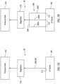
- the vent line 168 may include a single leg 182 between the LP cavity 140 and the flow regulator 170.
- the vent line 168 may include multiple legs 182A-C (generally referred to as "182") between the LP cavity 140 and the flow regulator 170.
- Each vent line leg 182 may be fluidly coupled to the LP cavity 140 at a respective port 172.
- the vent line legs 182 may then combine via a manifold 184 before (or after) extending across the core flowpath 62 (see FIGS. 1 and 2 ), and upstream of the flow regulator 170.
- the engine assembly 70 is described above in relation to the combustion section and its diffuser structure 86. It is contemplated, however, the engine assembly 70 may alternatively be configured for other sections of the turbine engine 20; e.g., within the turbine section 31. The present disclosure therefore is not limited to the exemplary arrangement of FIGS. 2-4 .
- the engine assembly 70 may be included in various turbine engines other than the exemplary gas turbine engine described above.
- the engine assembly 70 for example, may be included in a geared turbine engine where a geartrain connects one or more shafts to one or more rotors in a fan section, a compressor section and/or any other engine section.
- the engine assembly 70 may be included in a turbine engine configured without a geartrain; e.g., a direct drive turbine engine.
- the engine assembly 70 may be included in a geared or non-geared turbine engine configured with a single spool, with two spools (e.g., see FIG. 1 ), or with more than two spools.
- the turbine engine may be configured as a turbofan engine, a turbojet engine, a turboprop engine, a turboshaft engine, a propfan engine, a pusher fan engine or any other type of turbine engine.
- the turbine engine may alternatively be configured as an auxiliary power unit (APU) or an industrial gas turbine engine.
- APU auxiliary power unit
- the present disclosure therefore is not limited to any particular types or configurations of turbine engines.
Landscapes
- Engineering & Computer Science (AREA)
- Mechanical Engineering (AREA)
- General Engineering & Computer Science (AREA)
- Chemical & Material Sciences (AREA)
- Combustion & Propulsion (AREA)
- Turbine Rotor Nozzle Sealing (AREA)
Abstract
A method of operation is provided during which buffer air flows into a buffer cavity (124) in a turbine engine (20). The buffer cavity (124) surrounds a bearing compartment (100) in the turbine engine (20). Leakage air flows across a buffer seal device (150, 154) in the turbine engine (20). The buffer air and the leakage air are combined to provide combined air. The combined air is vented to a pressure sink (174) such that: a pressure of the buffer air within the buffer cavity (124) is maintained at or below a maximum buffer air threshold during operation of the turbine engine (20); and a flowrate of the leakage air across the buffer seal device (150, 154) is maintained at or above a minimum leakage air threshold during the operation of the turbine engine (20).
Description
- This invention was made with Government support awarded by the United States. The Government has certain rights in this invention.
- This disclosure relates generally to a turbine engine and, more particularly, to providing buffer air for a bearing compartment.
- It is known in the art to surround a bearing compartment with buffer air. Various systems and methods are known in the art for providing buffer air. While these known systems and methods have various benefits, there is still room in the art for improvement. There is a need in the art, for example, for systems and methods which may provide buffer air at a reduced pressure during one or more modes of turbine engine operation, without disrupting other internal air system functions requiring a continuous supply of high pressure air from a system surrounding the bearing compartment.
- According to an aspect of the present invention, a method of operation is provided during which buffer air flows into a buffer cavity in a turbine engine. The buffer cavity surrounds a bearing compartment in the turbine engine. Leakage air flows across a buffer seal device in the turbine engine. The buffer air and the leakage air are combined to provide combined air. The combined air is vented to a pressure sink such that: a pressure of the buffer air within the buffer cavity is maintained at or below a maximum buffer air threshold during operation of the turbine engine; and a flowrate of the leakage air across the buffer seal device is maintained at or above a minimum leakage air threshold during the operation of the turbine engine.
- According to another aspect of the present invention, a method of designing is provided during which a maximum buffer air threshold is identified for buffer air within a buffer cavity in a turbine engine. The buffer cavity is outboard of a bearing compartment in the turbine engine. A minimum leakage air threshold is identified for leakage air across a buffer seal device from a high pressure cavity in the turbine engine to a low pressure cavity in the turbine engine. The low pressure cavity is outboard of the buffer cavity. The high pressure cavity is outboard of the low pressure cavity. The buffer air combines with the leakage air within the low pressure cavity to provide combined air. A venting procedure is provided to vent the combined air from the low pressure cavity such that: a pressure of the buffer air within the buffer cavity is maintained at or below the maximum buffer air threshold during operation of the turbine engine; and a flowrate of the leakage air across the buffer seal device is maintained at or above the minimum leakage air threshold during the operation of the turbine engine.
- According to still another aspect of the present invention, an assembly is provided for a turbine engine. This assembly includes a stationary structure, a vent line, a valve and a control system. The stationary structure forms a bearing compartment, a buffer cavity, a low pressure cavity and a high pressure cavity. The buffer cavity is outboard of the bearing compartment. The low pressure cavity is outboard of the buffer cavity. The high pressure cavity is outboard of the low pressure cavity. The vent line is fluidly coupled with the low pressure cavity. The low pressure cavity is configured to direct leakage air from the high pressure cavity and buffer air from the buffer cavity into the vent line as low pressure air. The valve is fluidly coupled with and downstream of the vent line. The control system is configured to signal the valve to control venting of the low pressure air from the low pressure cavity through the vent line such that: a pressure of the buffer air within the buffer cavity is maintained at or below a maximum buffer air threshold; and a flowrate of the leakage air across the buffer seal device is maintained at or above a minimum leakage air threshold.
- According to any of the above, the valve may be configured as a two-position valve or a variable position valve.
- According to any of the above, the combined air may be to be vented using a valve.
- According to any of the above, the maximum buffer air threshold may be identified to account for variation in operation of the valve, deterioration of the valve and/or hysteresis of the valve.
- According to any of the above, the combined air may be vented to the pressure sink through a valve.
- According to any of the above, the valve may be configured as a discrete position valve.
- According to any of the above, the valve may be configured as a variable position valve.
- According to any of the above, the method may also include controlling operation of the valve using an electronic control system for the turbine engine.
- According to any of the above, the method may also include: monitoring an operational parameter of the turbine engine; and controlling operation of the valve based on the operational parameter.
- According to any of the above, at least some of the combined air may be vented to the pressure sink throughout the operation of the turbine engine.
- According to any of the above, the leakage air may flow across the buffer seal device from a high pressure cavity in the turbine engine to a low pressure cavity in the turbine engine. The buffer air may be combined with the leakage air in the low pressure cavity. The low pressure cavity may surround the buffer cavity. The high pressure cavity may surround the low pressure cavity.
- According to any of the above, a low pressure cavity wall in the turbine engine may include a sidewall and an endwall. The sidewall may be radially between and may form the low pressure cavity and the high pressure cavity. The endwall may project radially inward from the sidewall. The endwall may be axially between and may form the low pressure cavity and the high pressure cavity. The buffer seal device may seal a gap between the endwall and a rotating structure in the turbine engine.
- According to any of the above, the buffer cavity may be radially adjacent the bearing compartment. In addition or alternatively, the low pressure cavity may be radially adjacent the buffer cavity. In addition or alternatively, the high pressure cavity may be radially adjacent the low pressure cavity.
- According to any of the above, the buffer cavity may axially overlap the bearing compartment. In addition or alternatively, the low pressure cavity may axially overlap the buffer cavity. In addition or alternatively, the high pressure cavity may axially overlap the low pressure cavity.
- According to any of the above, a diffuser plenum in the turbine engine may surround the high pressure cavity. A combustor in the turbine engine may be disposed within the diffuser plenum.
- According to any of the above, the high pressure cavity may be radially inboard of a core flowpath within the turbine engine.
- According to any of the above, a bearing compartment wall in the turbine engine may include a sidewall, a first endwall and a second endwall. The sidewall may be radially between and may form the bearing compartment and the buffer cavity. The first endwall may project radially inward from the sidewall. The first endwall may be axially between and may form the bearing compartment and the buffer cavity. The second endwall may project radially inward from the sidewall. The second endwall may be axially between and may form the bearing compartment and the buffer cavity.
- According to any of the above, a bearing compartment wall in the turbine engine may be disposed between and may form the bearing compartment and the buffer cavity. Each of a plurality of bearing seal devices in the turbine engine may seal a respective gap between the bearing compartment wall and a rotating structure in the turbine engine. The bearing compartment may be disposed axially between the bearing seal devices.
- According to any of the above, both the buffer cavity and the bearing compartment may be formed by a stationary structure and a rotating structure in the turbine engine.
- The present disclosure may include any one or more of the individual features disclosed above and/or below alone or in any combination thereof.
- The foregoing features and the operation of the invention will become more apparent in light of the following description and the accompanying drawings.
-
-
FIG. 1 is a side cutaway illustration of a gas turbine engine. -
FIG. 2 is a partial schematic illustration of an engine assembly. -
FIG. 3 is a schematic illustration of a portion of the engine assembly. -
FIG. 4 is a partial schematic illustration of the engine assembly with flow arrows for a mode of operation. -
FIG. 5 is a graphical depiction of operation of the engine assembly with a discrete position valve. -
FIG. 6 is a graphical depiction of operation of the engine assembly with a variable position valve. -
FIGS. 7A and 7B are schematic illustrations of various air relief systems between a low pressure cavity and a pressure sink. -
FIG. 1 is a side cutaway illustration of agas turbine engine 20. Thisturbine engine 20 extends along anaxial centerline 22 between anupstream airflow inlet 24 and adownstream airflow exhaust 26. Theturbine engine 20 includes afan section 28, acompressor section 29, acombustor section 30 and aturbine section 31. Thecompressor section 29 includes a low pressure compressor (LPC)section 29A and a high pressure compressor (HPC)section 29B. Theturbine section 31 includes a high pressure turbine (HPT)section 31A and a low pressure turbine (LPT)section 31B. - The engine sections 28-31B are arranged sequentially along the
axial centerline 22 within an engine housing 34. This engine housing 34 includes an inner case 36 (e.g., a core case) and an outer case 38 (e.g., a fan case). Theinner case 36 may house one or more of theengine sections 29A-31B; e.g., a core of theturbine engine 20. Theouter case 38 may house at least thefan section 28. - Each of the
engine sections - The
fan rotor 40 is connected to ageartrain 46, for example, through afan shaft 48. Thegeartrain 46 and theLPC rotor 41 are connected to and driven by theLPT rotor 44 through alow speed shaft 50. At least (or only) theLPC rotor 41, theLPT rotor 44 and thelow speed shaft 50 may collectively form a lowspeed rotating structure 52; e.g., a low speed spool. TheHPC rotor 42 is connected to and driven by theHPT rotor 43 through ahigh speed shaft 54. At least (or only) theHPC rotor 42, theHPT rotor 43 and thehigh speed shaft 54 may collectively form a highspeed rotating structure 56; e.g., a high speed spool. Each of theengine rotating structures engine shafts bearings 58, some of which are schematically shown inFIG. 1 . Each of thesebearings 58 is connected to the engine housing 34 by an internal engine structure; e.g., duct walls, support structures (e.g., struts, frames, etc.) and the like. At least (or only) the internal engine structure and the engine housing 34 may collectively form astationary structure 60 of theturbine engine 20. - During operation, air enters the
turbine engine 20 through theairflow inlet 24. This air is directed through thefan section 28 and into acore flowpath 62 and abypass flowpath 64. Thecore flowpath 62 extends sequentially through theLPC section 29A, theHPC section 29B, thecombustor section 30, theHPT section 31A and theLPT section 31B; e.g., the engine core. The air within thecore flowpath 62 may be referred to as "core air". Thebypass flowpath 64 extends through a bypass duct, which bypasses the engine core. The air within thebypass flowpath 64 may be referred to as "bypass air". - The core air is compressed by the
LPC rotor 41 and theHPC rotor 42 and directed into acombustion chamber 66 of a (e.g., annular)combustor 68 in thecombustor section 30. Fuel is injected into thecombustion chamber 66 and mixed with the compressed core air to provide a fuel-air mixture. This fuel-air mixture is ignited and combustion products thereof flow through and sequentially cause theHPT rotor 43 and theLPT rotor 44 to rotate. The rotation of theHPT rotor 43 and theLPT rotor 44 respectively drive rotation of theHPC rotor 42 and theLPC rotor 41 and, thus, compression of the air received from a core airflow inlet. The rotation of theLPT rotor 44 also drives rotation of thefan rotor 40, whichfan rotor 40 propels bypass air through and out of thebypass flowpath 64. The propulsion of the bypass air may account for a majority of thrust generated by theturbine engine 20, e.g., more than seventy-five percent (75%) of engine thrust. Theturbine engine 20 of the present disclosure, however, is not limited to the foregoing exemplary thrust ratio. -
FIG. 2 illustrates anassembly 70 for theturbine engine 20. Thisengine assembly 70 includes an engine rotating structure 72 (e.g., the high speed rotating structure 56), an engine bearing 74 (e.g., one of the bearings 58), thestationary structure 60, abuffer air system 76 and anair relief system 78. Thestationary structure 60 ofFIG. 2 includes abearing compartment wall 80, abuffer cavity wall 82, a low pressure (LP)cavity wall 84, adiffuser structure 86 and thecombustor 68. - Referring to
FIG. 3 , the engine bearing 74 is configured to rotatably couple the engine rotating structure 72 to thestationary structure 60. Thestationary structure 60 may thereby rotatably support the engine rotating structure 72 through the engine bearing 74. Examples of the engine bearing 74 include, but are not limited to, a rolling element bearing and/or a thrust bearing. The engine bearing 74 ofFIG. 3 , for example, includes a bearinginner race 88, a bearingouter race 90 and a plurality of bearingelements 92. Theinner race 88 is mounted onto the engine rotating structure 72; e.g., onto a shaft 94 (e.g., the high speed shaft 54) of the engine rotating structure 72. Theouter race 90 circumscribes theinner race 88 and is mounted to abearing support 96 of thestationary structure 60. The bearingelements 92 are distributed circumferentially around a rotational axis 98 (e.g., the axial centerline 22) of the engine rotating structure 72 in a circular array. This array of the bearingelements 92 is disposed radially between and engaged with (e.g., contacts, rolls along, etc.) theinner race 88 and theouter race 90. - The bearing
compartment wall 80 is configured to form abearing compartment 100 in which the engine bearing 74 is housed. The bearingcompartment wall 80 ofFIG. 3 , for example, forms a radial outer peripheral boundary of thebearing compartment 100. The bearingcompartment wall 80 may also form one or more axial end peripheral boundaries of thebearing compartment 100. An inner peripheral boundary of thebearing compartment 100, however, may be formed by a combination of the bearingcompartment wall 80 and the engine rotating structure 72 and its engine shaft 94. In other embodiments, it is contemplated the inner peripheral boundary of thebearing compartment 100 may be (e.g., completely) formed by the engine rotating structure 72 and its engine shaft 94 and/or otherwise formed without the bearingcompartment wall 80. The bearingcompartment wall 80 ofFIG. 3 includes abearing compartment sidewall 102, a bearing compartment first endwall 104 and a bearing compartmentsecond endwall 106. Thebearing compartment 100 may also include a bearing compartment first endwall rim 108 ("first rim") and/or a bearing compartment second endwall rim 110 ("second rim"). - The
sidewall 102 is disposed at and/or along a radial outer side of thebearing compartment 100. Thesidewall 102 extends axially along the rotational axis 98 between and to the first endwall 104 and thesecond endwall 106. Thesidewall 102 extends circumferentially about (e.g., completely around) the rotational axis 98. Thesidewall 102 may thereby circumscribe the engine rotating structure 72 and form the radial outer peripheral boundary of thebearing compartment 100. Thesidewall 102 ofFIG. 3 has a non-straight (e.g., curved, bowed, bent, convex, splined, etc.) sectional geometry when viewed, for example, in a reference plane parallel with (e.g., including) the rotational axis 98; e.g., plane ofFIG. 3 . The present disclosure, however, is not limited to such an exemplary bearing compartment sidewall geometry. - The first endwall 104 is disposed at and/or along an axial first end of the
bearing compartment 100. The first endwall 104 is connected to (e.g., formed integral with or attached to) thesidewall 102. The first endwall 104 ofFIG. 3 projects radially inward (towards the rotational axis 98) from thesidewall 102 to a distalinner end 112 of the first endwall 104, which distalinner end 112 is spaced radially outboard of the engine rotating structure 72 by a gap; e.g., an air gap. The first endwall 104 extends circumferentially about (e.g., completely around) the rotational axis 98. The first endwall 104 may thereby circumscribe the engine rotating structure 72 and form the first axial end peripheral boundary of thebearing compartment 100. - The
second endwall 106 is disposed at and/or along an axial second end of thebearing compartment 100. Thesecond endwall 106 is connected to (e.g., formed integral with or attached to) thesidewall 102. Thesecond endwall 106 ofFIG. 3 projects radially inward (towards the rotational axis 98) from thesidewall 102 to a distalinner end 114 of thesecond endwall 106. This distalinner end 114 is spaced radially outboard of the engine rotating structure 72 by a gap; e.g., an air gap. Thesecond endwall 106 extends circumferentially about (e.g., completely around) the rotational axis 98. Thesecond endwall 106 may thereby circumscribe the engine rotating structure 72 and form the second axial end peripheral boundary of thebearing compartment 100. - The
first rim 108 is disposed at and/or along a radial inner side of thebearing compartment 100. Thefirst rim 108 is connected to (e.g., formed integral with or attached to) the first endwall 104. Thefirst rim 108 ofFIG. 3 projects axially out from the first endwall 104, along the rotational axis 98 and the engine rotating structure 72 towards thesecond endwall 106 and/or thesecond rim 110, to adistal end 116 of thefirst rim 108. Thefirst rim 108 is spaced radially outboard from the engine rotating structure 72 by a gap; e.g., an air gap. Thefirst rim 108 extends circumferentially about (e.g., completely around) the rotational axis 98. Thefirst rim 108 may thereby circumscribe the engine rotating structure 72. - A bearing compartment first seal device 118 ("first bearing seal device") is arranged with the bearing
compartment wall 80 and itsfirst rim 108 at (e.g., on, adjacent or proximate) thedistal end 116 of thefirst rim 108. This firstbearing seal device 118 is configured to seal an annular gap between (a) thebearing compartment wall 80 and itsfirst rim 108 and (b) the engine rotating structure 72. Examples of the firstbearing seal device 118 include, but are not limited to, a face seal device and a carbon seal device. - The
second rim 110 is disposed at and/or along the radial inner side of thebearing compartment 100. Thesecond rim 110 is connected to (e.g., formed integral with or attached to) thesecond endwall 106. Thesecond rim 110 ofFIG. 3 projects axially out from thesecond endwall 106, along the rotational axis 98 and the engine rotating structure 72 towards the first endwall 104 and/or thefirst rim 108, to adistal end 120 of thesecond rim 110. Thesecond rim 110 is spaced radially outboard from the engine rotating structure 72 by a gap; e.g., an air gap. Thesecond rim 110 extends circumferentially about (e.g., completely around) the rotational axis 98. Thesecond rim 110 may thereby circumscribe the engine rotating structure 72. - A bearing compartment second seal device 122 ("second bearing seal device") is arranged with the bearing
compartment wall 80 and itssecond rim 110 at (e.g., on, adjacent or proximate) thedistal end 120 of thesecond rim 110. This secondbearing seal device 122 is configured to seal an annular gap between (a) thebearing compartment wall 80 and itssecond rim 110 and (b) the engine rotating structure 72. Examples of the secondbearing seal device 122 include, but are not limited to, a face seal device and a carbon seal device. - With the foregoing arrangement, the
bearing compartment 100 is arranged and extends axially between and to the first endwall 104 and thesecond endwall 106. Thebearing compartment 100 is also arranged and extends axially between and to axially the firstbearing seal device 118 and the secondbearing seal device 122, where the engine bearing 74 is arranged axially between the firstbearing seal device 118 and the secondbearing seal device 122. A first end portion of thebearing compartment 100 is arranged and extends radially between and to thefirst rim 108 and thesidewall 102. A second end portion of thebearing compartment 100 is arranged and extends radially between and to thesecond rim 110 and thesidewall 102. An intermediate portion of thebearing compartment 100 is arranged and extends radially between and to the engine rotating structure 72 and thesidewall 102. Thisbearing compartment 100 further extends circumferentially about (e.g., completely around) the rotational axis 98. Thebearing compartment 100 may thereby circumscribe the engine rotating structure 72 and its engine shaft 94. - The
buffer cavity wall 82 is configured to form abuffer cavity 124. Thebuffer cavity wall 82 ofFIG. 3 , for example, forms a radial outer peripheral boundary of thebuffer cavity 124. Thebuffer cavity wall 82 may also form one or more axial end peripheral boundaries of thebuffer cavity 124. An inner peripheral boundary of thebuffer cavity 124, however, may be formed by a combination of the bearingcompartment wall 80 and the engine rotating structure 72 and its engine shaft 94. Thebuffer cavity wall 82 ofFIG. 3 includes abuffer cavity sidewall 126, a buffer cavity first endwall 128 and a buffer cavitysecond endwall 130. - The
sidewall 126 is disposed at and/or along a radial outer side of thebuffer cavity 124. Thesidewall 126 extends axially along the rotational axis 98 between and to thefirst endwall 128 and thesecond endwall 130. Thesidewall 126 extends circumferentially about (e.g., completely around) the rotational axis 98. Thesidewall 126 may thereby circumscribe the engine rotating structure 72 and thesidewall 102, and form the radial outer peripheral boundary of thebuffer cavity 124. Thesidewall 126 ofFIG. 3 has a non-straight (e.g., curved, bowed, bent, convex, splined, etc.) sectional geometry when viewed, for example, in the reference plane; e.g., the plane ofFIG. 3 . The present disclosure, however, is not limited to such an exemplary buffer cavity sidewall geometry. - The
first endwall 128 is disposed at and/or along an axial first end of thebuffer cavity 124. Thefirst endwall 128 is connected to (e.g., formed integral with or attached to) thesidewall 126. Thefirst endwall 128 ofFIG. 3 projects radially inward (towards the rotational axis 98) from thesidewall 126 to a distalinner end 132 of thefirst endwall 128. This distalinner end 132 is spaced radially outboard of the engine rotating structure 72, which may provide a (e.g., annular) firstcontrol leakage gap 134 radially between thefirst endwall 128 and the engine rotating structure 72. Thefirst endwall 128 extends circumferentially about (e.g., completely around) the rotational axis 98. Thefirst endwall 128 may thereby circumscribe the engine rotating structure 72 and form the first axial end peripheral boundary of thebuffer cavity 124. - The
second endwall 130 is disposed at and/or along an axial second end of thebuffer cavity 124. Thesecond endwall 130 is connected to (e.g., formed integral with or attached to) thesidewall 126. Thesecond endwall 130 ofFIG. 3 projects radially inward (towards the rotational axis 98) from thesidewall 126 to a distalinner end 136 of thesecond endwall 130. This distalinner end 136 is spaced radially outboard of the engine rotating structure 72, which may provide a (e.g., annular) secondcontrol leakage gap 138 radially between thesecond endwall 130 and the engine rotating structure 72. Thesecond endwall 130 extends circumferentially about (e.g., completely around) the rotational axis 98. Thesecond endwall 130 may thereby circumscribe the engine rotating structure 72 and form the second axial end peripheral boundary of thebuffer cavity 124. - With the foregoing arrangement, the
buffer cavity 124 is arranged axially between thefirst endwall 128 and thesecond endwall 130. Thebuffer cavity 124 is arranged radially between thesidewall 126 and the engine rotating structure 72 and its engine shaft 94. Thisbuffer cavity 124 further extends circumferentially about (e.g., completely around) the rotational axis 98. Thebuffer cavity 124 may thereby circumscribe the engine rotating structure 72 and its engine shaft 94 as well as the bearingcompartment wall 80. Thebuffer cavity 124 ofFIG. 3 therefore is (e.g., radially) outboard of and surrounds (in a radial direction and/or an axial direction) thebearing compartment 100. In particular, an outer portion of thebuffer cavity 124 extends radially between and to thesidewall 102 and thesidewall 126. A first end portion of thebuffer cavity 124 extends axially between and to the first endwall 104 and thefirst endwall 128. A second end portion of thebuffer cavity 124 extends axially between and to thesecond endwall 106 and thesecond endwall 130. A first inner portion of thebuffer cavity 124 extends radially between and to thefirst rim 108 and the engine rotating structure 72 and its engine shaft 94. This first inner portion also extend axially between and to the firstbearing seal device 118 and thefirst endwall 128 and its firstcontrol leakage gap 134. A second inner portion of thebuffer cavity 124 extends radially between and to thesecond rim 110 and the engine rotating structure 72 and its engine shaft 94. This second inner portion also extend axially between and to the secondbearing seal device 122 and thesecond endwall 130 and its secondcontrol leakage gap 138. - The
LP cavity wall 84 is configured to form a low pressure (LP)cavity 140. TheLP cavity wall 84 ofFIG. 3 , for example, forms a radial outer peripheral boundary of theLP cavity 140. TheLP cavity wall 84 may also form one or more axial end peripheral boundaries of theLP cavity 140. An inner peripheral boundary of theLP cavity 140, however, may be formed by a combination of thebuffer cavity wall 82 and the engine rotating structure 72 and its engine shaft 94. TheLP cavity wall 84 ofFIG. 3 includes a low pressure (LP)cavity sidewall 142, a low pressure (LP) cavity first endwall 144 and a low pressure (LP) cavitysecond endwall 146. - The
sidewall 142 is disposed at and/or along a radial outer side of theLP cavity 140. Thesidewall 142 extends axially along the rotational axis 98 between and to thefirst endwall 144 and thesecond endwall 146. Thesidewall 142 extends circumferentially about (e.g., completely around) the rotational axis 98. Thesidewall 142 may thereby circumscribe the engine rotating structure 72, thesidewall 126 and thesidewall 102, and form the radial outer peripheral boundary of theLP cavity 140. Thesidewall 142 ofFIG. 3 has a non-straight (e.g., curved, bowed, bent, convex, splined, etc.) sectional geometry when viewed, for example, in the reference plane; e.g., the plane ofFIG. 3 . The present disclosure, however, is not limited to such an exemplary LP cavity sidewall geometry. - The
first endwall 144 is disposed at and/or along an axial first end of theLP cavity 140. Thefirst endwall 144 is connected to (e.g., formed integral with or attached to) thesidewall 142. Thefirst endwall 144 ofFIG. 3 projects radially inward (towards the rotational axis 98) from thesidewall 142 to a distalinner end 148 of thefirst endwall 144. This distalinner end 148 is spaced radially outboard of the engine rotating structure 72. Thefirst endwall 144 extends circumferentially about (e.g., completely around) the rotational axis 98. Thefirst endwall 144 may thereby circumscribe the engine rotating structure 72. - A first buffer seal device 150 (e.g., a low pressure (LP) cavity seal device) is arranged with the
LP cavity wall 84 and itsfirst endwall 144 at (e.g., on, adjacent or proximate) thedistal end 148 of thefirst endwall 144. This firstbuffer seal device 150 is configured to seal an annular gap between (a) theLP cavity wall 84 and itsfirst endwall 144 and (b) the engine rotating structure 72. Examples of the firstbuffer seal device 150 include, but are not limited to, a face seal device, a carbon seal device, a brush seal device, a circumferentially segmented seal device, a KE seal device, a controlled gap seal device and a non-contact seal device. Examples of the non-contact seal device include, but are not limited to, a hydrostatic non-contact seal device and a hydrodynamic non-contact seal device. - The
second endwall 146 is disposed at and/or along an axial second end of theLP cavity 140. Thesecond endwall 146 is connected to (e.g., formed integral with or attached to) thesidewall 142. Thesecond endwall 146 ofFIG. 3 projects radially inward (towards the rotational axis 98) from thesidewall 142 to a distalinner end 152 of thesecond endwall 146. This distalinner end 152 is spaced radially outboard of the engine rotating structure 72. Thesecond endwall 146 extends circumferentially about (e.g., completely around) the rotational axis 98. Thesecond endwall 146 may thereby circumscribe the engine rotating structure 72. - A second buffer seal device 154 (e.g., a low pressure (LP) cavity seal device) is arranged with the
LP cavity wall 84 and itssecond endwall 146 at (e.g., on, adjacent or proximate) thedistal end 152 of thesecond endwall 146. This secondbuffer seal device 154 is configured to seal an annular gap between (a) theLP cavity wall 84 and itssecond endwall 146 and (b) the engine rotating structure 72. Examples of the secondbuffer seal device 154 include, but are not limited to, a face seal device, a carbon seal device, a brush seal device, a circumferentially segmented seal device, a KE seal device, a controlled gap seal device and a non-contact seal device. Examples of the non-contact seal device include, but are not limited to, a hydrostatic non-contact seal device and a hydrodynamic non-contact seal device. - With the foregoing arrangement, the
LP cavity 140 is arranged axially between thefirst endwall 144 and thesecond endwall 146. TheLP cavity 140 is arranged radially between thesidewall 142 and the engine rotating structure 72 and its engine shaft 94. ThisLP cavity 140 further extends circumferentially about (e.g., completely around) the rotational axis 98. TheLP cavity 140 may thereby circumscribe the engine rotating structure 72 and its engine shaft 94 as well as the bearingcompartment wall 80 and thebuffer cavity wall 82. TheLP cavity 140 ofFIG. 3 therefore is (e.g., radially) outboard of and surrounds (in a radial direction and/or an axial direction) thebearing compartment 100 and thebuffer cavity 124. In particular, an outer portion of theLP cavity 140 extends radially between and to thesidewall 126 and thesidewall 142. A first end portion of theLP cavity 140 extends axially between and to thefirst endwall 128 and thefirst endwall 144. This first end portion also extends axially between and to (or about) the firstcontrol leakage gap 134 and the firstbuffer seal device 150. A second end portion of theLP cavity 140 extends axially between and to thesecond endwall 130 and thesecond endwall 146. This second end portion also extends axially between and to (or about) the secondcontrol leakage gap 138 and the secondbuffer seal device 154. - Referring to
FIG. 2 , thediffuser structure 86 includes aninner diffuser case 156, anouter diffuser case 158 and adiffuser plenum 160. Theinner diffuser case 156 extends axially along the rotational axis 98, and may axially overlap at least a portion (or an entirety of) theLP cavity wall 84. Theinner diffuser case 156 extends circumferentially about (e.g., completely around) the rotational axis 98. Theinner diffuser case 156 may thereby circumscribe the engine rotating structure 72, thesidewall 142, thesidewall 126 and thesidewall 102. Thisinner diffuser case 156 is also spaced radially outboard from theLP cavity wall 84 and itssidewall 142. Theouter diffuser case 158 extends axially along the rotational axis 98, and may axially overlap at least a portion (or an entirety of) theinner diffuser case 156. Theouter diffuser case 158 extends circumferentially about (e.g., completely around) the rotational axis 98. Theouter diffuser case 158 may thereby circumscribe theinner diffuser case 156. Thisouter diffuser case 158 is also spaced radially outboard from theinner diffuser case 156. Thediffuser plenum 160 may thereby be arranged radially between and formed by theinner diffuser case 156 and theouter diffuser case 158. Thisdiffuser plenum 160 extends circumferentially about (e.g., completely around) the rotational axis 98. - With the foregoing arrangement, the
stationary structure 60 and the engine rotating structure 72 may collectively form a high pressure (HP)cavity 162. ThisHP cavity 162 is arranged and extends radially between and to theLP cavity wall 84 and theinner diffuser case 156. TheHP cavity 162 is located (e.g., radially) outboard of and (e.g., radially and/or axially) surrounds theLP cavity wall 84 and theLP cavity 140. TheLP cavity wall 84 ofFIG. 2 , for example, is disposed radially and/or axially within theHP cavity 162. - The
combustor 68 is disposed within thediffuser plenum 160. Here, thediffuser plenum 160 may receive compressed air from theHPC section 29B. The compressed air is diffused within thediffuser plenum 160, and the diffused air is directed into thecombustor 68 and itscombustion chamber 66 for mixing with the fuel and subsequent combustion. Thus, thecore flowpath 62 is located radially outboard of theHP cavity 162, theLP cavity 140, thebuffer cavity 124 and thebearing compartment 100. - The
buffer air system 76 is configured to deliver (e.g., relatively cool, high pressure) buffer air to thebuffer cavity 124. This buffer air may be air bled from thecore flowpath 62 out of the compressor section 29 (e.g., theHPC section 29B), and then run through a heat exchanger (e.g., a cooler). Thebuffer air system 76 ofFIG. 2 includes a buffer air conduit 164 (e.g., a pipe, a hose, etc.) which directs the buffer air into thebuffer cavity 124. Thebuffer air conduit 164, for example, may be fluidly coupled with aport 166 in thebuffer cavity wall 82 and itsfirst endwall 128. - The
air relief system 78 is configured to regulate fluid pressure (e.g., air pressure) within theLP cavity 140 and, thus, the fluidly coupledbuffer cavity 124. Theair relief system 78 ofFIG. 2 , for example, includes a vent line 168 (e.g., a conduit) and a flow regulator 170 (e.g., a valve). Thevent line 168 is fluidly coupled with aport 172 in theLP cavity wall 84 and its sidewall 142 (or the first endwall 144), and extends to theflow regulator 170. Theflow regulator 170 is fluidly coupled between thevent line 168 and apressure sink 174; e.g., the bypass flowpath 64 (seeFIG. 1 ), an environment external to theturbine engine 20, atail cone 176 for the turbine engine 20 (seeFIG. 1 ), etc. Theflow regulator 170 may be configured to adjust airflow out of theLP cavity 140 through thevent line 168 based on a mode of engine operation. For example, during an intermediate engine power setting (e.g., aircraft cruise), theflow regulator 170 may prevent or reduce the airflow vented to thepressure sink 174 from theLP cavity 140. This may reduce losses and, thus, increase engine efficiency at the intermediate engine power setting. However, during a high engine power setting (e.g., aircraft takeoff), theflow regulator 170 may increase the airflow vented to thepressure sink 174 from theLP cavity 140. This may reduce air pressure within theLP cavity 140 as well as thebuffer cavity 124, which may reduce parasitic losses (e.g., drag) on the engine rotating structure 72 and its engine shaft 94. It is believed the reduction is parasitic losses will outweigh any efficiency losses due to the increased venting. Reducing the air pressure within thebuffer cavity 124 also reduces pressure forces on (e.g., pressure differential across) thebearing seal devices flow regulator 170 may also reduce the airflow vented to thepressure sink 174 from theLP cavity 140 to ensure, for example, minimum leakage air flow requirements across thebearing seal devices bearing seal devices flow regulator 170 may be controlled by anelectronic control system 178; e.g., a FADEC or other controller for theturbine engine 20. - Referring to
FIG. 4 , during operation of theengine assembly 70, high pressure core air is bled from thecore flowpath 62 and directed into theHP cavity 162. A majority of this high pressure bleed air may pass through theHP cavity 162 for routing to one or more other areas of theturbine engine 20; e.g., to a turbine rotor for cooling, etc. Some of the high pressure bleed air, however, may leak across one or more of thebuffer seal devices LP cavity 140. Concurrently, the buffer air is directed into thebuffer cavity 124 from thebuffer air system 76 and itsbuffer air conduit 164. This buffer air provides an insulative barrier between the relatively cool air in thebearing compartment 100 and the relatively hot bleed air in theHP cavity 162. The buffer air flows through thebuffer cavity 124 and is directed into theLP cavity 140 through one or more of thecontrol leakage gaps buffer seal devices 150 and 154) in theLP cavity 140 combine to provide combined air; e.g., low pressure (LP) air. This combined air flows within theLP cavity 140 and its selectively vented through theair relief system 78 using theflow regulator 170. - The
flow regulator 170 ofFIG. 2 may be controlled by thecontrol system 178 to maintain a pressure of the buffer air in thebuffer cavity 124 within a select pressure range during turbine engine operation. Theflow regulator 170 may also or alternatively be controlled by thecontrol system 178 to maintain a flowrate of the leakage air across eachbuffer seal device LP cavity 140 through theair relief system 78 and itsmembers pressure sink 174 such that: (A) the pressure of the buffer air in thebuffer cavity 124 is maintained at or below a maximum buffer air threshold; and (B) the flowrate of the leakage air across eachbuffer seal device bearing seal devices flow regulator 170 and/or hysteresis in flow regulator actuation (e.g., actuation delay in opening or closing the valve). The minimum leakage air threshold may be selected based on various parameters including, but not limited to: flow requirements for seal device cooling / frictional heat mitigation (e.g., particularly for contact seal devices such as brush seals); flow requirements for proper operation of non-contact seal devices; and pressure requirements for proper operation of non-contact seal devices. -
FIG. 5 is a graphical depiction of operation of theengine assembly 70 where theflow regulator 170 is configured as a discrete position valve; e.g., a two position valve. Theflow regulator 170, for example, is operable in (e.g., only) a low flow position and a high flow position. In the low flow position, theflow regulator 170 has a non-zero first flow area. In the high flow position, theflow regulator 170 has a non-zero second flow area that is larger than the first flow area. As theturbine engine 20 is powered up, a mitigated (e.g., due to venting) pressure of the buffer air within thebuffer cavity 124 increases and approaches a maximum allowable pressure. The maximum buffer air threshold is set at apoint 180 below the maximum allowable pressure such that theflow regulator 170 opens; e.g., moves from the low flow position to the high flow position. By increasing the flow area through theflow regulator 170, additional combined air may be vented from theLP cavity 140 to thepressure sink 174. Theflow regulator 170 may thereby reduce the mitigated pressure of the buffer air within thebuffer cavity 124 to a lower level; e.g., seepoint 181. Theset point 180 may be selected to provide a pressure margin between the maximum buffer air threshold and the maximum allowable pressure to account for: possible variation in flow regulator operation; possible deterioration of the flow regulator; and/or hysteresis in flow regulator actuation. By contrast, the first flow area of theflow regulator 170 may be set such that the leakage air flowing across eachbuffer seal devices buffer seal device FIG. 5 (andFIG. 6 described below). -
FIG. 6 is a graphical depiction of operation of theengine assembly 70 where theflow regulator 170 is configured as a variable position valve; e.g., a variable area valve. Theflow regulator 170, for example, is operable to adjust (e.g., anywhere, or at various increments) between a low flow position and a high flow position. With such a configuration, theflow regulator 170 may be operated to maintain the mitigated pressure of the buffer air within thebuffer cavity 124 at (or about) the maximum buffer air threshold, for example, once the mitigated pressure reaches the maximum buffer air threshold. Thus, step changes in buffer pressure may be minimized and potential dynamic responses in other parts of the turbine engine internal air system may be avoided. In addition, providing a wider set of operating conditions may reduce performance impacts since an increase in combined air venting is gradually increased. - In some embodiments, the
flow regulator 170 ofFIG. 2 (e.g., the discrete position valve or the variable position valve) may be controlled based on an operational parameter (or parameters) of theturbine engine 20. Thecontrol system 178, for example, may monitor the operational parameter using data from a sensor system and/or model data. Based on a value of this monitored operation parameter, thecontrol system 178 may signal theflow regulator 170 to open or close to regulate the venting of the combined air to thepressure sink 174. Examples of the operational parameter include, but are not limited to, rotor speed, pressure, temperature, torque, thrust and flowrate. - In some embodiments, referring to
FIG. 7A , thevent line 168 may include a single leg 182 between theLP cavity 140 and theflow regulator 170. In other embodiments, referring toFIG. 7B , thevent line 168 may includemultiple legs 182A-C (generally referred to as "182") between theLP cavity 140 and theflow regulator 170. Each vent line leg 182 may be fluidly coupled to theLP cavity 140 at arespective port 172. The vent line legs 182 may then combine via a manifold 184 before (or after) extending across the core flowpath 62 (seeFIGS. 1 and2 ), and upstream of theflow regulator 170. - The
engine assembly 70 is described above in relation to the combustion section and itsdiffuser structure 86. It is contemplated, however, theengine assembly 70 may alternatively be configured for other sections of theturbine engine 20; e.g., within theturbine section 31. The present disclosure therefore is not limited to the exemplary arrangement ofFIGS. 2-4 . - The
engine assembly 70 may be included in various turbine engines other than the exemplary gas turbine engine described above. Theengine assembly 70, for example, may be included in a geared turbine engine where a geartrain connects one or more shafts to one or more rotors in a fan section, a compressor section and/or any other engine section. Alternatively, theengine assembly 70 may be included in a turbine engine configured without a geartrain; e.g., a direct drive turbine engine. Theengine assembly 70 may be included in a geared or non-geared turbine engine configured with a single spool, with two spools (e.g., seeFIG. 1 ), or with more than two spools. The turbine engine may be configured as a turbofan engine, a turbojet engine, a turboprop engine, a turboshaft engine, a propfan engine, a pusher fan engine or any other type of turbine engine. The turbine engine may alternatively be configured as an auxiliary power unit (APU) or an industrial gas turbine engine. The present disclosure therefore is not limited to any particular types or configurations of turbine engines. - While various embodiments of the present disclosure have been described, it will be apparent to those of ordinary skill in the art that many more embodiments and implementations are possible within the scope of the disclosure. For example, the present disclosure as described herein includes several aspects and embodiments that include particular features. Although these features may be described individually, it is within the scope of the present disclosure that some or all of these features may be combined with any one of the aspects and remain within the scope of the disclosure. Accordingly, the present disclosure is not to be restricted except in light of the attached claims and their equivalents.
Claims (15)
- A method of operation, comprising:flowing buffer air into a buffer cavity (124) in a turbine engine (20), the buffer cavity (124) surrounding a bearing compartment (100) in the turbine engine (20);flowing leakage air across a buffer seal device (150, 154) in the turbine engine (20);combining the buffer air and the leakage air to provide combined air; andventing the combined air to a pressure sink (174) such that:a pressure of the buffer air within the buffer cavity (124) is maintained at or below a maximum buffer air threshold during operation of the turbine engine (20); anda flowrate of the leakage air across the buffer seal device (150, 154) is maintained at or above a minimum leakage air threshold during the operation of the turbine engine (20).
- The method of claim 1, wherein the combined air is vented to the pressure sink (174) through a valve (170).
- The method of claim 2, wherein the valve (170) is configured as a discrete position valve (170), or a variable position valve (170).
- The method of claim 2 or 3, further comprising controlling operation of the valve (170) using an electronic control system (178) for the turbine engine (20).
- The method of any of claims 2 to 4, further comprising:monitoring an operational parameter of the turbine engine (20); andcontrolling operation of the valve (170) based on the operational parameter.
- The method of any preceding claim, wherein at least some of the combined air is vented to the pressure sink (174) throughout the operation of the turbine engine (20).
- The method of any preceding claim, whereinthe leakage air flows across the buffer seal device (150, 154) from a high pressure cavity (162) in the turbine engine (20) to a low pressure cavity (140) in the turbine engine (20);the buffer air is combined with the leakage air in the low pressure cavity (140);the low pressure cavity (140) surrounds the buffer cavity (124); andthe high pressure cavity (162) surrounds the low pressure cavity (140).
- The method of claim 7, whereina low pressure cavity wall (84) in the turbine engine (20) includes a sidewall (142) and an endwall (144);the sidewall (142) is radially between and forms the low pressure cavity (140) and the high pressure cavity (162);the endwall (144) projects radially inward from the sidewall (142), and the endwall (144) is axially between and forms the low pressure cavity (140) and the high pressure cavity (162); andthe buffer seal device (150, 154) seals a gap between the endwall (144) and a rotating structure (72) in the turbine engine (20).
- The method of claim 7 or 8, wherein:the buffer cavity (124) is radially adjacent and/or axially overlaps the bearing compartment (100);the low pressure cavity (140) is radially adjacent and/or axially overlaps the buffer cavity (124); and/orthe high pressure cavity (162) is radially adjacent and/or axially overlaps the low pressure cavity (140).
- The method of any of claims 7 to 9, whereina diffuser plenum (160) in the turbine engine (20) surrounds the high pressure cavity (162); anda combustor (68) in the turbine engine (20) is disposed within the diffuser plenum (160).
- The method of any of claims 7 to 10, wherein the high pressure cavity (162) is radially inboard of a core flowpath (62) within the turbine engine(20).
- The method of any preceding claim, wherein a bearing compartment wall (80) in the turbine engine (20) includes:a sidewall (102) radially between and forming the bearing compartment (100) and the buffer cavity (124);a first endwall (104) projecting radially inward from the sidewall (102), the first endwall (104) axially between and forming the bearing compartment (100) and the buffer cavity (124); anda second endwall (106) projecting radially inward from the sidewall (102), the second endwall (106) axially between and forming the bearing compartment (100) and the buffer cavity (124).
- The method of any preceding claim, whereina or the bearing compartment wall (80) in the turbine engine (20) is disposed between and forms the bearing compartment (100) and the buffer cavity (124);each of a plurality of bearing seal devices (118, 122) in the turbine engine (20) seal a respective gap between the bearing compartment wall (80) and a or the rotating structure (72) in the turbine engine (20); andthe bearing compartment (100) is disposed axially between the plurality of bearing seal devices (118, 122).
- The method of any preceding claim, wherein both the buffer cavity (124) and the bearing compartment (100) are formed by a stationary structure (60) and a or the rotating structure (72) in the turbine engine (20).
- An assembly for a turbine engine (20), comprising:a stationary structure (60) forming a bearing compartment (100), a buffer cavity (124), a low pressure cavity (140) and a high pressure cavity (162), the buffer cavity (124) outboard of the bearing compartment (100), the low pressure cavity (140) outboard of the buffer cavity (124), and the high pressure cavity (162) outboard of the low pressure cavity (140);a vent line fluidly coupled with the low pressure cavity (140), the low pressure cavity (140) configured to direct leakage air from the high pressure cavity (162) and buffer air from the buffer cavity (124) into the vent line (168) as low pressure air;a valve (170) fluidly coupled with and downstream of the vent line (168); anda control system (178) configured to signal the valve (170) to control venting of the low pressure air from the low pressure cavity (140) through the vent line such that:optionally wherein the valve (170) is configured as a two-position valve (170) or a variable position valve (170).a pressure of the buffer air within the buffer cavity (124) is maintained at or below a maximum buffer air threshold; anda flowrate of the leakage air across a buffer seal device (150, 154) is maintained at or above a minimum leakage air threshold,
Applications Claiming Priority (1)
| Application Number | Priority Date | Filing Date | Title |
|---|---|---|---|
| US18/105,632 US11905841B1 (en) | 2023-02-03 | 2023-02-03 | Buffer air method and system for a bearing compartment |
Publications (1)
| Publication Number | Publication Date |
|---|---|
| EP4411118A1 true EP4411118A1 (en) | 2024-08-07 |
Family
ID=89072984
Family Applications (1)
| Application Number | Title | Priority Date | Filing Date |
|---|---|---|---|
| EP23213838.8A Pending EP4411118A1 (en) | 2023-02-03 | 2023-12-01 | Buffer air method and system for a bearing component of a gas turbine |
Country Status (2)
| Country | Link |
|---|---|
| US (1) | US11905841B1 (en) |
| EP (1) | EP4411118A1 (en) |
Cited By (1)
| Publication number | Priority date | Publication date | Assignee | Title |
|---|---|---|---|---|
| EP4703560A1 (en) * | 2024-08-29 | 2026-03-04 | Pratt & Whitney Canada Corp. | Dual air source bearing assembly housing for an aircraft propulsion system |
Families Citing this family (1)
| Publication number | Priority date | Publication date | Assignee | Title |
|---|---|---|---|---|
| CN119957541B (en) * | 2025-01-03 | 2025-11-18 | 上海交通大学 | Supercritical carbon dioxide compressor low-leakage sealing system and control method |
Citations (5)
| Publication number | Priority date | Publication date | Assignee | Title |
|---|---|---|---|---|
| US4645415A (en) * | 1983-12-23 | 1987-02-24 | United Technologies Corporation | Air cooler for providing buffer air to a bearing compartment |
| US20130177406A1 (en) * | 2012-01-10 | 2013-07-11 | Rolls-Royce Plc | Gas turbine engine bearing chamber seals |
| US20160208697A1 (en) * | 2012-01-31 | 2016-07-21 | United Technologies Corporation | Mid-turbine frame buffer system |
| US20180291816A1 (en) * | 2017-04-11 | 2018-10-11 | United Technologies Corporation | Vented buffer air supply for intershaft seals |
| US20180340469A1 (en) * | 2017-05-25 | 2018-11-29 | General Electric Company | Interdigitated turbine engine air bearing and method of operation |
Family Cites Families (8)
| Publication number | Priority date | Publication date | Assignee | Title |
|---|---|---|---|---|
| US3528241A (en) * | 1969-02-24 | 1970-09-15 | Gen Electric | Gas turbine engine lubricant sump vent and circulating system |
| US7836675B2 (en) * | 2006-02-21 | 2010-11-23 | General Electric Company | Supercore sump vent pressure control |
| WO2008105815A2 (en) * | 2006-08-22 | 2008-09-04 | Rolls-Royce North American Technologies, Inc. | Gas turbine engine with intermediate speed booster |
| DE102007058953A1 (en) | 2007-12-07 | 2009-06-10 | Rolls-Royce Deutschland Ltd & Co Kg | Bearing chamber pressure system |
| US20130192251A1 (en) * | 2012-01-31 | 2013-08-01 | Peter M. Munsell | Buffer system that communicates buffer supply air to one or more portions of a gas turbine engine |
| US10724431B2 (en) | 2012-01-31 | 2020-07-28 | Raytheon Technologies Corporation | Buffer system that communicates buffer supply air to one or more portions of a gas turbine engine |
| US9617916B2 (en) * | 2012-11-28 | 2017-04-11 | Pratt & Whitney Canada Corp. | Gas turbine engine with bearing buffer air flow and method |
| US11572837B2 (en) * | 2021-01-22 | 2023-02-07 | Pratt & Whitney Canada Corp. | Buffer fluid delivery system and method for a shaft seal of a gas turbine engine |
-
2023
- 2023-02-03 US US18/105,632 patent/US11905841B1/en active Active
- 2023-12-01 EP EP23213838.8A patent/EP4411118A1/en active Pending
Patent Citations (5)
| Publication number | Priority date | Publication date | Assignee | Title |
|---|---|---|---|---|
| US4645415A (en) * | 1983-12-23 | 1987-02-24 | United Technologies Corporation | Air cooler for providing buffer air to a bearing compartment |
| US20130177406A1 (en) * | 2012-01-10 | 2013-07-11 | Rolls-Royce Plc | Gas turbine engine bearing chamber seals |
| US20160208697A1 (en) * | 2012-01-31 | 2016-07-21 | United Technologies Corporation | Mid-turbine frame buffer system |
| US20180291816A1 (en) * | 2017-04-11 | 2018-10-11 | United Technologies Corporation | Vented buffer air supply for intershaft seals |
| US20180340469A1 (en) * | 2017-05-25 | 2018-11-29 | General Electric Company | Interdigitated turbine engine air bearing and method of operation |
Cited By (1)
| Publication number | Priority date | Publication date | Assignee | Title |
|---|---|---|---|---|
| EP4703560A1 (en) * | 2024-08-29 | 2026-03-04 | Pratt & Whitney Canada Corp. | Dual air source bearing assembly housing for an aircraft propulsion system |
Also Published As
| Publication number | Publication date |
|---|---|
| US11905841B1 (en) | 2024-02-20 |
Similar Documents
| Publication | Publication Date | Title |
|---|---|---|
| US8887485B2 (en) | Three spool gas turbine engine having a clutch and compressor bypass | |
| EP3244036B1 (en) | Dual-use air turbine system for a gas turbine engine | |
| EP3845748B1 (en) | Turbine engine system with heat exchanger in bypassable secondary duct | |
| US20180134407A1 (en) | Method and apparatus for undercowl flow diversion cooling | |
| EP2375005B1 (en) | Method for controlling turbine blade tip seal clearance | |
| US20180016933A1 (en) | Method and system for soak-back mitigation by active cooling | |
| EP4411118A1 (en) | Buffer air method and system for a bearing component of a gas turbine | |
| CA2949293A1 (en) | Gas turbine engine fluid cooling systems and methods of assembling the same | |
| US11913376B2 (en) | Pressurized airflow to rotate compressor during engine shutdown | |
| CA2943448A1 (en) | Method and system for modulated turbine cooling | |
| EP4506542A2 (en) | Turbine engine tip clearance control utilizing electric machine | |
| EP4464881A1 (en) | Pressure control for bifurcated flow of a turbine engine | |
| EP4411116A1 (en) | Buffer air system for a bearing compartment of a gas turbine | |
| CN117432528A (en) | Cooling air delivery system and method | |
| US11867089B1 (en) | Gas turbine engine with combustor section mounted modulated compressor air cooling system | |
| EP4589130A2 (en) | Regulating core air bled from a turbine engine core flowpath | |
| US20250092826A1 (en) | Core compartment vent during engine shutdown to reduced bowed rotor start | |
| US12286930B1 (en) | Turbine engine fan case with bleed air for tip injection and heat exchanger cooling | |
| US11512594B2 (en) | System and method for modulating airflow into a bore of a rotor to control blade tip clearance | |
| EP4692511A1 (en) | Assemblies for a turbine engine | |
| US12454911B2 (en) | Bleeding core air from a turbine engine core flowpath | |
| US20250197013A1 (en) | Open rotor aircraft propulsion system with anti-icing system | |
| US12163465B1 (en) | Turbine engine with couplable rotating assemblies | |
| US12492649B2 (en) | Lubrication system and methods of lubricating a gearbox assembly | |
| US20250354519A1 (en) | Gas turbine engine having cooling systems |
Legal Events
| Date | Code | Title | Description |
|---|---|---|---|
| PUAI | Public reference made under article 153(3) epc to a published international application that has entered the european phase |
Free format text: ORIGINAL CODE: 0009012 |
|
| STAA | Information on the status of an ep patent application or granted ep patent |
Free format text: STATUS: THE APPLICATION HAS BEEN PUBLISHED |
|
| AK | Designated contracting states |
Kind code of ref document: A1 Designated state(s): AL AT BE BG CH CY CZ DE DK EE ES FI FR GB GR HR HU IE IS IT LI LT LU LV MC ME MK MT NL NO PL PT RO RS SE SI SK SM TR |
|
| STAA | Information on the status of an ep patent application or granted ep patent |
Free format text: STATUS: REQUEST FOR EXAMINATION WAS MADE |
|
| 17P | Request for examination filed |
Effective date: 20250207 |