EP3244036B1 - Dual-use air turbine system for a gas turbine engine - Google Patents
Dual-use air turbine system for a gas turbine engine Download PDFInfo
- Publication number
- EP3244036B1 EP3244036B1 EP17171127.8A EP17171127A EP3244036B1 EP 3244036 B1 EP3244036 B1 EP 3244036B1 EP 17171127 A EP17171127 A EP 17171127A EP 3244036 B1 EP3244036 B1 EP 3244036B1
- Authority
- EP
- European Patent Office
- Prior art keywords
- valve
- engine
- variable area
- turbine
- main valve
- Prior art date
- Legal status (The legal status is an assumption and is not a legal conclusion. Google has not performed a legal analysis and makes no representation as to the accuracy of the status listed.)
- Active
Links
- 230000007613 environmental effect Effects 0.000 claims description 22
- 239000007858 starting material Substances 0.000 claims description 19
- 238000000034 method Methods 0.000 claims description 17
- 238000011144 upstream manufacturing Methods 0.000 claims description 5
- 239000007789 gas Substances 0.000 description 32
- 239000000567 combustion gas Substances 0.000 description 5
- 238000013461 design Methods 0.000 description 5
- 239000000446 fuel Substances 0.000 description 3
- 230000005540 biological transmission Effects 0.000 description 2
- 238000001816 cooling Methods 0.000 description 2
- 230000008569 process Effects 0.000 description 2
- 206010037660 Pyrexia Diseases 0.000 description 1
- 238000006243 chemical reaction Methods 0.000 description 1
- 238000002485 combustion reaction Methods 0.000 description 1
- 230000008878 coupling Effects 0.000 description 1
- 238000010168 coupling process Methods 0.000 description 1
- 238000005859 coupling reaction Methods 0.000 description 1
- 230000001419 dependent effect Effects 0.000 description 1
- 230000000694 effects Effects 0.000 description 1
- 239000000284 extract Substances 0.000 description 1
- 239000012530 fluid Substances 0.000 description 1
- 230000006870 function Effects 0.000 description 1
- 230000007246 mechanism Effects 0.000 description 1
- 238000012986 modification Methods 0.000 description 1
- 230000004048 modification Effects 0.000 description 1
- 238000012544 monitoring process Methods 0.000 description 1
- 230000003287 optical effect Effects 0.000 description 1
- 238000012545 processing Methods 0.000 description 1
- 238000004513 sizing Methods 0.000 description 1
- 239000013589 supplement Substances 0.000 description 1
- 230000032258 transport Effects 0.000 description 1
Images

Classifications
-
- B—PERFORMING OPERATIONS; TRANSPORTING
- B64—AIRCRAFT; AVIATION; COSMONAUTICS
- B64D—EQUIPMENT FOR FITTING IN OR TO AIRCRAFT; FLIGHT SUITS; PARACHUTES; ARRANGEMENTS OR MOUNTING OF POWER PLANTS OR PROPULSION TRANSMISSIONS IN AIRCRAFT
- B64D13/00—Arrangements or adaptations of air-treatment apparatus for aircraft crew or passengers, or freight space, or structural parts of the aircraft
- B64D13/06—Arrangements or adaptations of air-treatment apparatus for aircraft crew or passengers, or freight space, or structural parts of the aircraft the air being conditioned
- B64D13/08—Arrangements or adaptations of air-treatment apparatus for aircraft crew or passengers, or freight space, or structural parts of the aircraft the air being conditioned the air being heated or cooled
-
- B—PERFORMING OPERATIONS; TRANSPORTING
- B64—AIRCRAFT; AVIATION; COSMONAUTICS
- B64D—EQUIPMENT FOR FITTING IN OR TO AIRCRAFT; FLIGHT SUITS; PARACHUTES; ARRANGEMENTS OR MOUNTING OF POWER PLANTS OR PROPULSION TRANSMISSIONS IN AIRCRAFT
- B64D13/00—Arrangements or adaptations of air-treatment apparatus for aircraft crew or passengers, or freight space, or structural parts of the aircraft
- B64D13/06—Arrangements or adaptations of air-treatment apparatus for aircraft crew or passengers, or freight space, or structural parts of the aircraft the air being conditioned
-
- B—PERFORMING OPERATIONS; TRANSPORTING
- B64—AIRCRAFT; AVIATION; COSMONAUTICS
- B64D—EQUIPMENT FOR FITTING IN OR TO AIRCRAFT; FLIGHT SUITS; PARACHUTES; ARRANGEMENTS OR MOUNTING OF POWER PLANTS OR PROPULSION TRANSMISSIONS IN AIRCRAFT
- B64D15/00—De-icing or preventing icing on exterior surfaces of aircraft
- B64D15/02—De-icing or preventing icing on exterior surfaces of aircraft by ducted hot gas or liquid
- B64D15/04—Hot gas application
-
- B—PERFORMING OPERATIONS; TRANSPORTING
- B64—AIRCRAFT; AVIATION; COSMONAUTICS
- B64F—GROUND OR AIRCRAFT-CARRIER-DECK INSTALLATIONS SPECIALLY ADAPTED FOR USE IN CONNECTION WITH AIRCRAFT; DESIGNING, MANUFACTURING, ASSEMBLING, CLEANING, MAINTAINING OR REPAIRING AIRCRAFT, NOT OTHERWISE PROVIDED FOR; HANDLING, TRANSPORTING, TESTING OR INSPECTING AIRCRAFT COMPONENTS, NOT OTHERWISE PROVIDED FOR
- B64F1/00—Ground or aircraft-carrier-deck installations
- B64F1/34—Ground or aircraft-carrier-deck installations for starting propulsion plant
-
- F—MECHANICAL ENGINEERING; LIGHTING; HEATING; WEAPONS; BLASTING
- F02—COMBUSTION ENGINES; HOT-GAS OR COMBUSTION-PRODUCT ENGINE PLANTS
- F02C—GAS-TURBINE PLANTS; AIR INTAKES FOR JET-PROPULSION PLANTS; CONTROLLING FUEL SUPPLY IN AIR-BREATHING JET-PROPULSION PLANTS
- F02C1/00—Gas-turbine plants characterised by the use of hot gases or unheated pressurised gases, as the working fluid
- F02C1/02—Gas-turbine plants characterised by the use of hot gases or unheated pressurised gases, as the working fluid the working fluid being an unheated pressurised gas
-
- F—MECHANICAL ENGINEERING; LIGHTING; HEATING; WEAPONS; BLASTING
- F02—COMBUSTION ENGINES; HOT-GAS OR COMBUSTION-PRODUCT ENGINE PLANTS
- F02C—GAS-TURBINE PLANTS; AIR INTAKES FOR JET-PROPULSION PLANTS; CONTROLLING FUEL SUPPLY IN AIR-BREATHING JET-PROPULSION PLANTS
- F02C3/00—Gas-turbine plants characterised by the use of combustion products as the working fluid
- F02C3/04—Gas-turbine plants characterised by the use of combustion products as the working fluid having a turbine driving a compressor
-
- F—MECHANICAL ENGINEERING; LIGHTING; HEATING; WEAPONS; BLASTING
- F02—COMBUSTION ENGINES; HOT-GAS OR COMBUSTION-PRODUCT ENGINE PLANTS
- F02C—GAS-TURBINE PLANTS; AIR INTAKES FOR JET-PROPULSION PLANTS; CONTROLLING FUEL SUPPLY IN AIR-BREATHING JET-PROPULSION PLANTS
- F02C6/00—Plural gas-turbine plants; Combinations of gas-turbine plants with other apparatus; Adaptations of gas- turbine plants for special use
- F02C6/04—Gas-turbine plants providing heated or pressurised working fluid for other apparatus, e.g. without mechanical power output
- F02C6/06—Gas-turbine plants providing heated or pressurised working fluid for other apparatus, e.g. without mechanical power output providing compressed gas
- F02C6/08—Gas-turbine plants providing heated or pressurised working fluid for other apparatus, e.g. without mechanical power output providing compressed gas the gas being bled from the gas-turbine compressor
-
- F—MECHANICAL ENGINEERING; LIGHTING; HEATING; WEAPONS; BLASTING
- F02—COMBUSTION ENGINES; HOT-GAS OR COMBUSTION-PRODUCT ENGINE PLANTS
- F02C—GAS-TURBINE PLANTS; AIR INTAKES FOR JET-PROPULSION PLANTS; CONTROLLING FUEL SUPPLY IN AIR-BREATHING JET-PROPULSION PLANTS
- F02C7/00—Features, components parts, details or accessories, not provided for in, or of interest apart form groups F02C1/00 - F02C6/00; Air intakes for jet-propulsion plants
- F02C7/26—Starting; Ignition
- F02C7/268—Starting drives for the rotor, acting directly on the rotor of the gas turbine to be started
- F02C7/275—Mechanical drives
- F02C7/277—Mechanical drives the starter being a separate turbine
-
- B—PERFORMING OPERATIONS; TRANSPORTING
- B64—AIRCRAFT; AVIATION; COSMONAUTICS
- B64D—EQUIPMENT FOR FITTING IN OR TO AIRCRAFT; FLIGHT SUITS; PARACHUTES; ARRANGEMENTS OR MOUNTING OF POWER PLANTS OR PROPULSION TRANSMISSIONS IN AIRCRAFT
- B64D13/00—Arrangements or adaptations of air-treatment apparatus for aircraft crew or passengers, or freight space, or structural parts of the aircraft
- B64D13/06—Arrangements or adaptations of air-treatment apparatus for aircraft crew or passengers, or freight space, or structural parts of the aircraft the air being conditioned
- B64D2013/0603—Environmental Control Systems
- B64D2013/0618—Environmental Control Systems with arrangements for reducing or managing bleed air, using another air source, e.g. ram air
-
- B—PERFORMING OPERATIONS; TRANSPORTING
- B64—AIRCRAFT; AVIATION; COSMONAUTICS
- B64D—EQUIPMENT FOR FITTING IN OR TO AIRCRAFT; FLIGHT SUITS; PARACHUTES; ARRANGEMENTS OR MOUNTING OF POWER PLANTS OR PROPULSION TRANSMISSIONS IN AIRCRAFT
- B64D13/00—Arrangements or adaptations of air-treatment apparatus for aircraft crew or passengers, or freight space, or structural parts of the aircraft
- B64D13/06—Arrangements or adaptations of air-treatment apparatus for aircraft crew or passengers, or freight space, or structural parts of the aircraft the air being conditioned
- B64D2013/0603—Environmental Control Systems
- B64D2013/0648—Environmental Control Systems with energy recovery means, e.g. using turbines
-
- F—MECHANICAL ENGINEERING; LIGHTING; HEATING; WEAPONS; BLASTING
- F05—INDEXING SCHEMES RELATING TO ENGINES OR PUMPS IN VARIOUS SUBCLASSES OF CLASSES F01-F04
- F05D—INDEXING SCHEME FOR ASPECTS RELATING TO NON-POSITIVE-DISPLACEMENT MACHINES OR ENGINES, GAS-TURBINES OR JET-PROPULSION PLANTS
- F05D2220/00—Application
- F05D2220/30—Application in turbines
- F05D2220/32—Application in turbines in gas turbines
-
- F—MECHANICAL ENGINEERING; LIGHTING; HEATING; WEAPONS; BLASTING
- F05—INDEXING SCHEMES RELATING TO ENGINES OR PUMPS IN VARIOUS SUBCLASSES OF CLASSES F01-F04
- F05D—INDEXING SCHEME FOR ASPECTS RELATING TO NON-POSITIVE-DISPLACEMENT MACHINES OR ENGINES, GAS-TURBINES OR JET-PROPULSION PLANTS
- F05D2250/00—Geometry
- F05D2250/90—Variable geometry
-
- F—MECHANICAL ENGINEERING; LIGHTING; HEATING; WEAPONS; BLASTING
- F05—INDEXING SCHEMES RELATING TO ENGINES OR PUMPS IN VARIOUS SUBCLASSES OF CLASSES F01-F04
- F05D—INDEXING SCHEME FOR ASPECTS RELATING TO NON-POSITIVE-DISPLACEMENT MACHINES OR ENGINES, GAS-TURBINES OR JET-PROPULSION PLANTS
- F05D2260/00—Function
- F05D2260/40—Transmission of power
- F05D2260/403—Transmission of power through the shape of the drive components
- F05D2260/4031—Transmission of power through the shape of the drive components as in toothed gearing
-
- F—MECHANICAL ENGINEERING; LIGHTING; HEATING; WEAPONS; BLASTING
- F05—INDEXING SCHEMES RELATING TO ENGINES OR PUMPS IN VARIOUS SUBCLASSES OF CLASSES F01-F04
- F05D—INDEXING SCHEME FOR ASPECTS RELATING TO NON-POSITIVE-DISPLACEMENT MACHINES OR ENGINES, GAS-TURBINES OR JET-PROPULSION PLANTS
- F05D2260/00—Function
- F05D2260/60—Fluid transfer
- F05D2260/606—Bypassing the fluid
-
- F—MECHANICAL ENGINEERING; LIGHTING; HEATING; WEAPONS; BLASTING
- F05—INDEXING SCHEMES RELATING TO ENGINES OR PUMPS IN VARIOUS SUBCLASSES OF CLASSES F01-F04
- F05D—INDEXING SCHEME FOR ASPECTS RELATING TO NON-POSITIVE-DISPLACEMENT MACHINES OR ENGINES, GAS-TURBINES OR JET-PROPULSION PLANTS
- F05D2260/00—Function
- F05D2260/85—Starting
-
- Y—GENERAL TAGGING OF NEW TECHNOLOGICAL DEVELOPMENTS; GENERAL TAGGING OF CROSS-SECTIONAL TECHNOLOGIES SPANNING OVER SEVERAL SECTIONS OF THE IPC; TECHNICAL SUBJECTS COVERED BY FORMER USPC CROSS-REFERENCE ART COLLECTIONS [XRACs] AND DIGESTS
- Y02—TECHNOLOGIES OR APPLICATIONS FOR MITIGATION OR ADAPTATION AGAINST CLIMATE CHANGE
- Y02T—CLIMATE CHANGE MITIGATION TECHNOLOGIES RELATED TO TRANSPORTATION
- Y02T50/00—Aeronautics or air transport
- Y02T50/50—On board measures aiming to increase energy efficiency
Definitions
- This disclosure relates to gas turbine engines, and more particularly to a dual-use air turbine system for a gas turbine engine.
- Gas turbine engines are used in numerous applications, one of which is for providing thrust to an aircraft.
- Compressed air is typically tapped at a high pressure location near the combustor for auxiliary uses, such as environmental control of the aircraft and wing anti-ice.
- this high pressure air is typically hotter than can safely be supported by ductwork and delivery to the aircraft.
- a pre-cooler or heat exchanger is used to cool hightemperature engine bleed air and is typically located near the engine such that excessively hot air is not ducted through the wing of the aircraft for safety reasons. Diverting higher pressure and higher temperature air from the engine beyond the pressure needed reduces engine efficiency.
- US 5143329 A discloses a dual-use air turbine system.
- WO 01/23724 A2 discloses a dual-use air turbine system and a method of using a dual-use air turbine system.
- US 5114103 A discloses a dual-use air turbine system according to the preamble of claim 1 and a method of using a dual-use air turbine system according to the preamble of claim 7.
- a system comprising a dual-use air turbine system and a gas turbine engine of an aircraft in accordance with claim 1.
- Technical effects include utilizing an air turbine for starting a gas turbine engine and to boost engine efficiency by reducing engine bleed air temperature before it enters the aircraft wing while converting the thermal energy back into rotational energy driving the engine.
- Gas turbine engines are rotary-type combustion turbine engines built around a power core made up of a compressor, combustor and turbine, arranged in flow series with an upstream inlet and downstream exhaust.
- the compressor compresses air from the inlet, which is mixed with fuel in the combustor and ignited to generate hot combustion gas.
- the turbine extracts energy from the expanding combustion gas, and drives the compressor via a common shaft. Energy is delivered in the form of rotational energy in the shaft, reactive thrust from the exhaust, or both. Compressed air can be extracted from various stages as bleed air.
- Embodiments include a variable area air turbine that is used for engine starting and cooling of higher temperature engine bleed air for aircraft environmental control systems. Rather than relying entirely on a pre-cooler/heat exchanger to cool engine bleed air, the variable area air turbine can provide cooling while returning rotational energy back to the engine. This can reduce sizing requirements and in some instances eliminate the need for a pre-cooler while increasing engine operating efficiency.
- Gas turbine engines provide efficient, reliable power for aviation .
- Smaller-scale engines such as auxiliary power units typically utilize a one-spool design, with co-rotating compressor and turbine sections.
- Larger-scale jet engines are generally arranged into a number of coaxially nested spools, which operate at different pressures and temperatures, and rotate at different speeds.
- each spool is subdivided into a number of stages, which are formed of alternating rows of rotor blades and stator vane airfoils.
- the airfoils are shaped to turn, accelerate and compress the working fluid flow, or to generate lift for conversion to rotational energy in the turbine.
- turbojet engines thrust is generated primarily from the exhaust.
- Modern fixed-wing aircraft generally employ turbofan and turboprop designs, in which the low pressure spool is coupled to a propulsion fan or propeller in turbofan with two turbines.
- turbofans with three turbines one turbine drives the fan, one turbine drives the first compressor section and the third turbine drives the second compressor section.
- Turboshaft engines are typically used on rotary-wing aircraft, including helicopters.
- Turbofan engines are commonly divided into high and low bypass configurations.
- High bypass turbofans generate thrust primarily from the fan, which drives airflow through a bypass duct oriented around the engine core. This design is common on commercial aircraft and military transports, where noise and fuel efficiency are primary concerns.
- Low bypass turbofans generate proportionally more thrust from the exhaust flow, providing greater specific thrust for use on high-performance aircraft, including supersonic jet fighters.
- Unducted (open rotor) turbofans and ducted propeller engines are also known, in a variety of counter-rotating and aft-mounted configurations.
- FIG. 1 a cross-sectional view of a gas turbine engine 10, in a turbofan configuration is illustrated.
- the illustrated gas turbine engine 10 includes a propulsion fan 12 mounted inside a bypass duct 14 upstream of a fan exit guide vane 13.
- a power core of the engine is formed by a compressor section 16, a combustor 18 and a turbine section 20.
- Rotor blades (or airfoils) 21 in the compressor section 16 and/or the turbine section 20 are arranged in stages 38 with corresponding stator vane airfoils 39.
- compressor section 16 includes a low pressure compressor 22 (a lower pressure compressor section) and a high pressure compressor 24 (a highest pressure compressor section).
- the turbine section 20 includes high a pressure turbine 26 and a low pressure turbine 28.
- the low pressure compressor 22 is rotationally coupled to the low pressure turbine 28 via a low pressure shaft 30, thereby forming the low pressure spool or low spool 31.
- High pressure compressor 24 is rotationally coupled to the high pressure turbine 26 via a high spool shaft 32, forming the high pressure spool or high spool 33.
- the fan 12 accelerates air flow from an inlet 34 through bypass duct 14, generating thrust.
- the core airflow is compressed in the low pressure compressor 22 and the high pressure compressor 24 and then the compressed airflow is mixed with fuel in the combustor 18 and ignited to generate combustion gas.
- the combustion gas expands to drive the high and low pressure turbines 26 and 28, which are rotationally coupled to high pressure compressor 24 and low pressure compressor 22, respectively. Expanded combustion gases exit through exhaust nozzle 36, which is shaped to generate additional thrust from the exhaust gas flow.
- the low pressure shaft 30 may be coupled to a low pressure compressor and then to a fan 12 via geared drive mechanism 37, providing improved fan speed control for increased efficiency and reduced engine noise.
- Propulsion fan 12 may also function as a first-stage compressor for gas turbine engine 10, with low pressure compressor 22 performing as an intermediate-stage compressor or booster in front of the high pressure compressor. Alternatively, the low pressure compressor stages are absent, and air from fan 12 is provided directly to high pressure compressor 24, or to an independently rotating intermediate compressor spool.
- the gas turbine engine 10 may have a range of different shaft and spool geometries, including one-spool, two-spool and three-spool configurations, in both co-rotating and counter-rotating designs.
- Gas turbine engine 10 may also be configured as a low bypass turbofan, an open-rotor turbofan, a ducted or un-ducted propeller engine, or an industrial gas turbine.
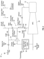
- FIG. 2 depicts a dual-use air turbine system 40 that interfaces with elements of the gas turbine engine 10 of FIG. 1 .
- the dual-use air turbine system 40 includes a variable area air turbine 42 mechanically linked to a spool (e.g., high spool 33) of the gas turbine engine 10 through a multi-speed gear set 44.
- a turbine coupling 46 links the variable area air turbine 42 through transmission 48 to high spool shaft 32.
- the transmission 48 can include the multi-speed gear set 44 and optionally a clutch 50 to selectively engage the variable area air turbine 42 to drive rotation of the spool. While a specific configuration is depicted in FIG. 2 , other configurations are contemplated within the scope of the invention.
- a plurality of valves 60, 62, 64, 66, 68 in pneumatic ducting 52 can direct an engine start air flow 54 (from aircraft ducting 56) through an inlet 58 of the variable area air turbine 42 and drive rotation of the spool (e.g., high spool 33) during an engine start mode of operation when starting the gas turbine engine 10.
- the spool e.g., high spool 33
- the valves 60, 62, 64, 66, 68 are further operable to direct an engine bleed air flow 70 from a compressor section (e.g., high pressure compressor 24) of the gas turbine engine 10 through the inlet 58 of the variable area air turbine 42 and drive rotation of the spool (e.g., high spool 33) in combination with the rotational force provided by the high pressure turbine 26 during an environmental control system active mode of operation.
- the aircraft ducting 56 can provide the engine start air flow 54 from an auxiliary power unit, ground cart, or other sources (not depicted) when the gas turbine engine 10 is to be started.
- the aircraft ducting 56 can receive an environmental control system and/or wing anti-ice air flow 72 from the dual-use air turbine system 40 when the gas turbine engine 10 is running (e.g., at idle or higher power) and a need is detected.
- the environmental control system and/or wing anti-ice air flow 72 can be provided by the engine bleed air flow 70 directly and/or after all or a portion of the engine bleed air flow 70 has passed through the variable area air turbine 42 depending on the demand and current operating conditions.
- the engine bleed air flow 70 can be provided from a lower pressure tap 74 of the high pressure compressor 24 by a first check valve 60.
- the engine bleed air flow 70 can be provided from a higher pressure tap 76 of the high pressure compressor 24 by a high pressure shut-off valve 62.
- the first check valve 60 is opened during a high power condition of the gas turbine engine 10, while the high pressure shut-off valve 62 is opened during an engine idle condition of the gas turbine engine 10.
- the higher pressure tap 76 can be used as the source for the engine bleed air flow 70 near idle and as power increases until the lower pressure tap 74 can provide a demanded temperature/pressure level.
- a main valve 64 is located upstream of the inlet 58 of the variable area air turbine 42 and provides a flow path between the aircraft ducting 56 and the inlet 58 when open.
- the main valve 64 also provides a flow path for the engine bleed air flow 70 to the aircraft ducting 56 when open.
- a starter air valve 66 is located downstream of an outlet 78 of the variable area air turbine 42. The starter air valve 66 provides a flow path between outlet 78 and an exhaust port 80 (e.g., to a turbine exhaust case or overboard) when open.
- a second check valve 68 is located between the outlet 78 of the variable area air turbine 42 and the main valve 64. The second check valve 68 provides a flow path between the outlet 78 and the aircraft ducting 56 when open.
- the first check valve 60 and the second check valve 68 can be passively controlled based on the pressure differential on each side of each valve.
- the high pressure shutoff valve 62, main valve 64, and starter air valve 66 can be controlled by one or more controllers (depicted generally as controller 82).
- the controller 82 may include memory to store instructions that are executed by a processor.
- the executable instructions may be stored or organized in any manner and at any level of abstraction, such as in connection with a controlling and/or monitoring operation of one or more systems of the gas turbine engine 10 of FIG. 1 and/or other aircraft systems.
- the processor can be any type of central processing unit (CPU), including a general purpose processor, a digital signal processor, a microcontroller, an application specific integrated circuit (ASIC), a field programmable gate array, or the like.
- the memory may include random access memory (RAM), read only memory (ROM), or other electronic, optical, magnetic, or any other computer readable medium onto which is stored data and control algorithms in a non-transitory form.
- the controller 82 can be embodied in an individual line-replaceable unit, within a control system (e.g., in an electronic engine control), and/or distributed between multiple electronic systems.
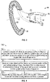
- variable area air turbine 42 can be embodied in various forms known in the art having a variable area feature to alter flow characteristics through the variable area air turbine 42.
- the variable area air turbine 42 can include turbine nozzle segments 84 such as that depicted in FIG. 3 .
- a turbine nozzle segment 84 includes an arcuate outer vane platform segment 86 and an arcuate inner vane platform segment 88 radially spaced apart from each other.
- the arcuate outer vane platform segment 86 may form an outer portion of the variable area air turbine 42 and the arcuate inner vane platform segment 88 may form an inner portion of variable area air turbine 42 to at least partially define an annular turbine nozzle flow path.
- the circumferentially adjacent vane platform segments 86, 88 define split lines 90 which thermally uncouple adjacent turbine nozzle segments 84 which may be conventionally sealed therebetween, with, for example only, spline seals. That is, the temperature environment of the variable area air turbine 42 and the substantial aerodynamic and thermal loads are accommodated by the plurality of circumferentially adjoining nozzle segments 84 which collectively form a full, annular ring about a centerline axis X of the variable area air turbine 42.
- Each turbine nozzle segment 84 includes a multiple (two shown) of circumferentially spaced apart turbine vanes 92, 94 which extend radially between the vane platform segments 86, 88.
- each nozzle segment 84 doublet includes one fixed turbine vane 92 and one rotational turbine vane 94 between the vane platform segments 86, 88 to provide a rigid structural assembly which accommodates thermal and aerodynamic loads during operation. That is, the full, annular ring formed by the multiple of turbine nozzle segments 84 provides a vane portion of one stage in the variable area air turbine 42, which is defined by the alternating fixed and rotational turbine vanes 92, 94 in this example. Rotational turbine vane 94 movement results in a variable flow area to increase or choke flow through the variable area air turbine 42 as needed.
- FIG. 4 is a process flow of a method 100 of using the dual-use air turbine system 40 of FIG. 2 according to an embodiment.
- the method 100 is described with reference to FIGS. 1-3 . Although described primarily in reference to the gas turbine engine 10 of FIG. 1 , it will be understood that the method 100 can also be applied to other configurations.
- valves 60, 62, 64, 66, 68 in pneumatic ducting 52 are controlled (e.g., by controller 82 and/or pressure differentials) to direct engine start air flow 54 through inlet 58 of variable area air turbine 42 and drive rotation of a spool (e.g., high spool 33) of the gas turbine engine 10 during an engine start mode of operation.
- a spool e.g., high spool 33
- engine bleed air flow 70 is directed from a compressor section (e.g., high pressure compressor 24) of the gas turbine engine 10 through the inlet 58 of the variable area air turbine 42 to drive rotation of the spool during an environmental control system active mode of operation.
- rotational force driven by the variable area air turbine 42 can supplement the rotational force provided by the high pressure turbine 26 in driving rotation of the high spool shaft 32.
- a portion of the engine bleed air flow 70 bypasses the variable area air turbine 42 when a wing anti-ice condition is present.
- the first check valve 60 can be opened during a high power condition of the gas turbine engine 10, and the high pressure shut-off valve 62 can be opened during an engine idle condition of the gas turbine engine 10.
- the main valve 64 and the starter air valve 66 can be opened during the engine start mode of operation to establish a flow path from aircraft ducting 56 through the main valve 64, the variable area air turbine 42, the starter air valve 66, and the exhaust port 80.
- the starter air valve 66 can be opened during an environmental control system off mode of operation to establish a flow path for the engine bleed air flow 70 through the variable area air turbine 42, the starter air valve 66, and the exhaust port 80.
- the main valve 64 is opened during the environmental control system active mode of operation at a minimum pressure engine idle condition to establish a flow path for the engine bleed air flow 70 through the main valve 64 to the aircraft ducting 56.
- the main valve 64 is closed and the second check valve 68 is opened during the environmental control system active mode of operation at an engine off idle condition and at a high power condition to establish a flow path for the engine bleed air flow 70 through the variable area air turbine 42 and the second check valve 68 to the aircraft ducting 56.
- the main valve 64 can be opened and the second check valve 68 can be opened during the environmental control system active mode of operation with wing anti-ice on to establish a flow path for the engine bleed air flow 70 to the aircraft ducting 56 through the variable area air turbine 42 and the main valve 64.
- the variable area air turbine 42 can be selectively engaged or disengaged with the high spool shaft 32 to drive rotation of the high spool 33 during start and during environmental control system operation.
Description
- This disclosure relates to gas turbine engines, and more particularly to a dual-use air turbine system for a gas turbine engine.
- Gas turbine engines are used in numerous applications, one of which is for providing thrust to an aircraft. Compressed air is typically tapped at a high pressure location near the combustor for auxiliary uses, such as environmental control of the aircraft and wing anti-ice. However, this high pressure air is typically hotter than can safely be supported by ductwork and delivery to the aircraft. Thus, a pre-cooler or heat exchanger is used to cool hightemperature engine bleed air and is typically located near the engine such that excessively hot air is not ducted through the wing of the aircraft for safety reasons. Diverting higher pressure and higher temperature air from the engine beyond the pressure needed reduces engine efficiency.
-
US 5143329 A discloses a dual-use air turbine system. -
WO 01/23724 A2 -
US 5114103 A discloses a dual-use air turbine system according to the preamble of claim 1 and a method of using a dual-use air turbine system according to the preamble of claim 7. - According to a first aspect of the invention, there is provided a system comprising a dual-use air turbine system and a gas turbine engine of an aircraft in accordance with claim 1.
- According to a second aspect of the invention, there is provided a method of using a dual-use air turbine system for a gas turbine engine in accordance with claim 7.
- Various optional features of the first and second aspects of the invention are defined in the dependent claims.
- Technical effects include utilizing an air turbine for starting a gas turbine engine and to boost engine efficiency by reducing engine bleed air temperature before it enters the aircraft wing while converting the thermal energy back into rotational energy driving the engine.
- The subject matter which is regarded as the present invention is particularly pointed out and distinctly claimed in the claims at the conclusion of the specification. The foregoing and other features, and advantages of the present invention are apparent from the following detailed description taken in conjunction with the accompanying drawings in which:
-
FIG. 1 is a cross-sectional view of a gas turbine engine; -
FIG. 2 is a schematic view of dual-use air turbine system according to an embodiment of the disclosure; -
FIG. 3 is an expanded view of a vane portion of a turbine stage within the air turbine ofFIG. 2 ; and -
FIG. 4 is a process flow of a method according to embodiments of the disclosure. - While the above-identified drawing figures set forth one or more embodiments of the invention, other embodiments are also contemplated. In all cases, the description presents the invention by way of representation and not limitation. It should be understood that numerous other modifications and embodiments can be devised by those skilled in the art, which fall within the scope of the invention as defined in the claims. The figures may not be drawn to scale, and applications and embodiments of the present invention may include features and components not specifically shown in the drawings. Like reference numerals identify similar structural elements.
- Various embodiments of the present invention are related to a system comprising a dual-use air turbine system and a gas turbine engine. Gas turbine engines are rotary-type combustion turbine engines built around a power core made up of a compressor, combustor and turbine, arranged in flow series with an upstream inlet and downstream exhaust. The compressor compresses air from the inlet, which is mixed with fuel in the combustor and ignited to generate hot combustion gas. The turbine extracts energy from the expanding combustion gas, and drives the compressor via a common shaft. Energy is delivered in the form of rotational energy in the shaft, reactive thrust from the exhaust, or both. Compressed air can be extracted from various stages as bleed air.
- Embodiments include a variable area air turbine that is used for engine starting and cooling of higher temperature engine bleed air for aircraft environmental control systems. Rather than relying entirely on a pre-cooler/heat exchanger to cool engine bleed air, the variable area air turbine can provide cooling while returning rotational energy back to the engine. This can reduce sizing requirements and in some instances eliminate the need for a pre-cooler while increasing engine operating efficiency.
- Gas turbine engines provide efficient, reliable power for aviation . Smaller-scale engines such as auxiliary power units typically utilize a one-spool design, with co-rotating compressor and turbine sections. Larger-scale jet engines are generally arranged into a number of coaxially nested spools, which operate at different pressures and temperatures, and rotate at different speeds.
- The individual compressor and turbine sections in each spool are subdivided into a number of stages, which are formed of alternating rows of rotor blades and stator vane airfoils. The airfoils are shaped to turn, accelerate and compress the working fluid flow, or to generate lift for conversion to rotational energy in the turbine.
- Aviation applications include turbojet, turbofan, turboprop and turboshaft engines. In turbojet engines, thrust is generated primarily from the exhaust. Modern fixed-wing aircraft generally employ turbofan and turboprop designs, in which the low pressure spool is coupled to a propulsion fan or propeller in turbofan with two turbines. Alternatively, in turbofans with three turbines, one turbine drives the fan, one turbine drives the first compressor section and the third turbine drives the second compressor section. Turboshaft engines are typically used on rotary-wing aircraft, including helicopters.
- Turbofan engines are commonly divided into high and low bypass configurations. High bypass turbofans generate thrust primarily from the fan, which drives airflow through a bypass duct oriented around the engine core. This design is common on commercial aircraft and military transports, where noise and fuel efficiency are primary concerns. Low bypass turbofans generate proportionally more thrust from the exhaust flow, providing greater specific thrust for use on high-performance aircraft, including supersonic jet fighters. Unducted (open rotor) turbofans and ducted propeller engines are also known, in a variety of counter-rotating and aft-mounted configurations.
- Referring now to
FIG. 1 , a cross-sectional view of agas turbine engine 10, in a turbofan configuration is illustrated. The illustratedgas turbine engine 10 includes apropulsion fan 12 mounted inside abypass duct 14 upstream of a fan exit guide vane 13. A power core of the engine is formed by acompressor section 16, acombustor 18 and aturbine section 20. Rotor blades (or airfoils) 21 in thecompressor section 16 and/or theturbine section 20 are arranged instages 38 with correspondingstator vane airfoils 39. - In the two-spool, high bypass configuration of
FIG. 1 ,compressor section 16 includes a low pressure compressor 22 (a lower pressure compressor section) and a high pressure compressor 24 (a highest pressure compressor section). Theturbine section 20 includes high apressure turbine 26 and alow pressure turbine 28. - The
low pressure compressor 22 is rotationally coupled to thelow pressure turbine 28 via alow pressure shaft 30, thereby forming the low pressure spool orlow spool 31.High pressure compressor 24 is rotationally coupled to thehigh pressure turbine 26 via ahigh spool shaft 32, forming the high pressure spool orhigh spool 33. - During operation of the
gas turbine engine 10, thefan 12 accelerates air flow from aninlet 34 throughbypass duct 14, generating thrust. The core airflow is compressed in thelow pressure compressor 22 and thehigh pressure compressor 24 and then the compressed airflow is mixed with fuel in thecombustor 18 and ignited to generate combustion gas. - The combustion gas expands to drive the high and
low pressure turbines high pressure compressor 24 andlow pressure compressor 22, respectively. Expanded combustion gases exit throughexhaust nozzle 36, which is shaped to generate additional thrust from the exhaust gas flow. In advanced turbofan designs with a low pressure turbine and a high pressure turbine, thelow pressure shaft 30 may be coupled to a low pressure compressor and then to afan 12 via geareddrive mechanism 37, providing improved fan speed control for increased efficiency and reduced engine noise.Propulsion fan 12 may also function as a first-stage compressor forgas turbine engine 10, withlow pressure compressor 22 performing as an intermediate-stage compressor or booster in front of the high pressure compressor. Alternatively, the low pressure compressor stages are absent, and air fromfan 12 is provided directly tohigh pressure compressor 24, or to an independently rotating intermediate compressor spool. - The
gas turbine engine 10 may have a range of different shaft and spool geometries, including one-spool, two-spool and three-spool configurations, in both co-rotating and counter-rotating designs.Gas turbine engine 10 may also be configured as a low bypass turbofan, an open-rotor turbofan, a ducted or un-ducted propeller engine, or an industrial gas turbine. -
FIG. 2 depicts a dual-useair turbine system 40 that interfaces with elements of thegas turbine engine 10 ofFIG. 1 . The dual-useair turbine system 40 includes a variablearea air turbine 42 mechanically linked to a spool (e.g., high spool 33) of thegas turbine engine 10 through a multi-speed gear set 44. Aturbine coupling 46 links the variablearea air turbine 42 throughtransmission 48 tohigh spool shaft 32. Thetransmission 48 can include the multi-speed gear set 44 and optionally a clutch 50 to selectively engage the variablearea air turbine 42 to drive rotation of the spool. While a specific configuration is depicted inFIG. 2 , other configurations are contemplated within the scope of the invention. - In the system depicted in
FIG. 2 , a plurality ofvalves pneumatic ducting 52 can direct an engine start air flow 54 (from aircraft ducting 56) through aninlet 58 of the variablearea air turbine 42 and drive rotation of the spool (e.g., high spool 33) during an engine start mode of operation when starting thegas turbine engine 10. Thevalves bleed air flow 70 from a compressor section (e.g., high pressure compressor 24) of thegas turbine engine 10 through theinlet 58 of the variablearea air turbine 42 and drive rotation of the spool (e.g., high spool 33) in combination with the rotational force provided by thehigh pressure turbine 26 during an environmental control system active mode of operation. Theaircraft ducting 56 can provide the enginestart air flow 54 from an auxiliary power unit, ground cart, or other sources (not depicted) when thegas turbine engine 10 is to be started. Theaircraft ducting 56 can receive an environmental control system and/or winganti-ice air flow 72 from the dual-useair turbine system 40 when thegas turbine engine 10 is running (e.g., at idle or higher power) and a need is detected. The environmental control system and/or winganti-ice air flow 72 can be provided by the enginebleed air flow 70 directly and/or after all or a portion of the enginebleed air flow 70 has passed through the variablearea air turbine 42 depending on the demand and current operating conditions. - The engine
bleed air flow 70 can be provided from alower pressure tap 74 of thehigh pressure compressor 24 by afirst check valve 60. Alternatively, the enginebleed air flow 70 can be provided from ahigher pressure tap 76 of thehigh pressure compressor 24 by a high pressure shut-offvalve 62. Thefirst check valve 60 is opened during a high power condition of thegas turbine engine 10, while the high pressure shut-offvalve 62 is opened during an engine idle condition of thegas turbine engine 10. Thehigher pressure tap 76 can be used as the source for the enginebleed air flow 70 near idle and as power increases until thelower pressure tap 74 can provide a demanded temperature/pressure level. - A
main valve 64 is located upstream of theinlet 58 of the variablearea air turbine 42 and provides a flow path between theaircraft ducting 56 and theinlet 58 when open. Themain valve 64 also provides a flow path for the enginebleed air flow 70 to theaircraft ducting 56 when open. Astarter air valve 66 is located downstream of anoutlet 78 of the variablearea air turbine 42. Thestarter air valve 66 provides a flow path betweenoutlet 78 and an exhaust port 80 (e.g., to a turbine exhaust case or overboard) when open. Asecond check valve 68 is located between theoutlet 78 of the variablearea air turbine 42 and themain valve 64. Thesecond check valve 68 provides a flow path between theoutlet 78 and theaircraft ducting 56 when open. Thefirst check valve 60 and thesecond check valve 68 can be passively controlled based on the pressure differential on each side of each valve. The highpressure shutoff valve 62,main valve 64, andstarter air valve 66 can be controlled by one or more controllers (depicted generally as controller 82). - The
controller 82 may include memory to store instructions that are executed by a processor. The executable instructions may be stored or organized in any manner and at any level of abstraction, such as in connection with a controlling and/or monitoring operation of one or more systems of thegas turbine engine 10 ofFIG. 1 and/or other aircraft systems. The processor can be any type of central processing unit (CPU), including a general purpose processor, a digital signal processor, a microcontroller, an application specific integrated circuit (ASIC), a field programmable gate array, or the like. Also, in embodiments, the memory may include random access memory (RAM), read only memory (ROM), or other electronic, optical, magnetic, or any other computer readable medium onto which is stored data and control algorithms in a non-transitory form. Thecontroller 82 can be embodied in an individual line-replaceable unit, within a control system (e.g., in an electronic engine control), and/or distributed between multiple electronic systems. - The variable
area air turbine 42 can be embodied in various forms known in the art having a variable area feature to alter flow characteristics through the variablearea air turbine 42. As one example, the variablearea air turbine 42 can includeturbine nozzle segments 84 such as that depicted inFIG. 3 . Aturbine nozzle segment 84 includes an arcuate outervane platform segment 86 and an arcuate innervane platform segment 88 radially spaced apart from each other. The arcuate outervane platform segment 86 may form an outer portion of the variablearea air turbine 42 and the arcuate innervane platform segment 88 may form an inner portion of variablearea air turbine 42 to at least partially define an annular turbine nozzle flow path. - The circumferentially adjacent
vane platform segments lines 90 which thermally uncouple adjacentturbine nozzle segments 84 which may be conventionally sealed therebetween, with, for example only, spline seals. That is, the temperature environment of the variablearea air turbine 42 and the substantial aerodynamic and thermal loads are accommodated by the plurality of circumferentially adjoiningnozzle segments 84 which collectively form a full, annular ring about a centerline axis X of the variablearea air turbine 42. - Each
turbine nozzle segment 84 includes a multiple (two shown) of circumferentially spaced apartturbine vanes vane platform segments turbine vane 92 and onerotational turbine vane 94 between thevane platform segments turbine nozzle segments 84 provides a vane portion of one stage in the variablearea air turbine 42, which is defined by the alternating fixed androtational turbine vanes Rotational turbine vane 94 movement results in a variable flow area to increase or choke flow through the variablearea air turbine 42 as needed. -
FIG. 4 is a process flow of amethod 100 of using the dual-useair turbine system 40 ofFIG. 2 according to an embodiment. Themethod 100 is described with reference toFIGS. 1-3 . Although described primarily in reference to thegas turbine engine 10 ofFIG. 1 , it will be understood that themethod 100 can also be applied to other configurations. Atblock 102,valves pneumatic ducting 52 are controlled (e.g., bycontroller 82 and/or pressure differentials) to direct enginestart air flow 54 throughinlet 58 of variablearea air turbine 42 and drive rotation of a spool (e.g., high spool 33) of thegas turbine engine 10 during an engine start mode of operation. Atblock 104, enginebleed air flow 70 is directed from a compressor section (e.g., high pressure compressor 24) of thegas turbine engine 10 through theinlet 58 of the variablearea air turbine 42 to drive rotation of the spool during an environmental control system active mode of operation. In the environmental control system active mode of operation, rotational force driven by the variablearea air turbine 42 can supplement the rotational force provided by thehigh pressure turbine 26 in driving rotation of thehigh spool shaft 32. Atblock 106, a portion of the enginebleed air flow 70 bypasses the variablearea air turbine 42 when a wing anti-ice condition is present. - Various operating conditions are contemplated. For example, the
first check valve 60 can be opened during a high power condition of thegas turbine engine 10, and the high pressure shut-offvalve 62 can be opened during an engine idle condition of thegas turbine engine 10. Themain valve 64 and thestarter air valve 66 can be opened during the engine start mode of operation to establish a flow path fromaircraft ducting 56 through themain valve 64, the variablearea air turbine 42, thestarter air valve 66, and theexhaust port 80. Thestarter air valve 66 can be opened during an environmental control system off mode of operation to establish a flow path for the enginebleed air flow 70 through the variablearea air turbine 42, thestarter air valve 66, and theexhaust port 80. Themain valve 64 is opened during the environmental control system active mode of operation at a minimum pressure engine idle condition to establish a flow path for the enginebleed air flow 70 through themain valve 64 to theaircraft ducting 56. Themain valve 64 is closed and thesecond check valve 68 is opened during the environmental control system active mode of operation at an engine off idle condition and at a high power condition to establish a flow path for the enginebleed air flow 70 through the variablearea air turbine 42 and thesecond check valve 68 to theaircraft ducting 56. Themain valve 64 can be opened and thesecond check valve 68 can be opened during the environmental control system active mode of operation with wing anti-ice on to establish a flow path for the enginebleed air flow 70 to theaircraft ducting 56 through the variablearea air turbine 42 and themain valve 64. Depending on the operating conditions, the variablearea air turbine 42 can be selectively engaged or disengaged with thehigh spool shaft 32 to drive rotation of thehigh spool 33 during start and during environmental control system operation. - The present invention is not to be seen as limited by the foregoing description, but is only limited by the scope of the appended claims.
Claims (12)
- A system comprising a dual-use air turbine system (40) and a gas turbine engine (10) of an aircraft, wherein the gas turbine engine comprises a spool (33) and a compressor section (24), and wherein the dual-use air turbine system comprises:a variable area air turbine (42) configured to be mechanically linked to the spool (33) of the gas turbine engine through a multi-speed gear set (44);a plurality of valves (60; 62; 64; 66; 68) in pneumatic ducting (52) operable to direct an engine start air flow (54) through an inlet (58) of the variable area air turbine to thereby drive rotation of the spool during an engine start mode of operation; anda controller (82);wherein the valves comprise a first valve (60) that is a check valve and a high pressure shutoff valve (62), a starter air valve (66) located downstream of an outlet (78) of the variable area air turbine, and a main valve (64);wherein the dual-use air turbine system is configured to provide engine bleed air flow (70) from a lower pressure tap (74) of the compressor section (24) by the first valve or a higher pressure tap (76) of the compressor section by the high pressure shut-off valve; andwherein the system is configured to provide the engine bleed air flow to both the main valve and to the inlet of the variable area air turbine;characterised in that:the dual-use air turbine system comprises a second valve (68) that is a check valve;the main valve (64) is in parallel with the second valve,the main valve (64) is located upstream of the inlet of the variable area air turbine in the engine start mode of operation;the main valve (64) is in parallel with the variable area air turbine in an environmental control system active mode of operation;and the main valve is located such that the second valve is located between the outlet of the variable area air turbine and the main valve; andthe controller (82) is configured to:control, during an environmental control system active mode of operation at an engine off idle condition and at a high power condition of the gas turbine engine (10), the main valve (64) to close, the starter air valve (66) to close and thereby passively control the second valve (68) to open to direct the engine bleed air flow (70) from a compressor section (24) of the gas turbine engine, through the inlet of the variable area air turbine and drive rotation of the spool, through the second valve (68) and to aircraft ducting (56) that is in communication with the pneumatic ducting; andto, during the environmental control system active mode of operation at a minimum pressure engine idle condition, open the main valve (64) to establish a flow path for the engine bleed air flow (70) through the main valve to the aircraft ducting (56) that is in communication with the pneumatic ducting.
- The system as in claim 1, wherein the first valve is configured to open during a high power condition of the gas turbine engine (10) and the controller is configured to open the high pressure shut-off valve during an engine idle condition of the gas turbine engine.
- The system as in claim 1 or 2, wherein the controller is configured to open the main valve and the starter air valve during the engine start mode of operation to establish a flow path from aircraft ducting (56) that is in communication with the pneumatic ducting, and through the main valve, the variable area air turbine, the starter air valve, and an exhaust port (80).
- The system as in any preceding claim, wherein the controller is configured to open the starter air valve (66) during an environmental control system off mode of operation to establish a flow path for the engine bleed air flow (70) through the variable area air turbine (42), the starter air valve, and an exhaust port (80).
- The system as in any preceding claim, wherein the controller is configured to open the main valve (64) and the second valve (68) is configured to open based on a pressure differential across the second valve (68) during the environmental control system active mode of operation with wing anti-ice on to establish a flow path for the engine bleed air flow (70) to aircraft ducting (56) that is in communication with the pneumatic ducting, and through the variable area air turbine (42) and the main valve.
- The system as in any preceding claim, further comprising a clutch (50) to selectively engage the variable area air turbine (42) to drive rotation of the spool (33).
- A method of using a dual-use air turbine system (40) for a gas turbine engine (10) of an aircraft, the method comprising:controlling (102) a plurality of valves (60; 62; 64; 66; 68) in pneumatic ducting (52) to direct an engine start air flow (54) through an inlet (58) of a variable area air turbine (42) and drive rotation of a spool (35) of the gas turbine engine during an engine start mode of operation;wherein the variable area air turbine is mechanically linked to the spool of the gas turbine engine through a multi-speed gear set (44);wherein the valves comprise a first valve (60) that is a check valve and a high pressure shutoff valve (62), a starter air valve (66) located downstream of an outlet (78) of the variable area air turbine, and a main valve (64);wherein an engine bleed air flow (70) is provided from a lower pressure tap (74) of a compressor section (24) of the gas turbine engine by the first check valve or a higher pressure tap (76) of the compressor section by the high pressure shut-off valve; andwherein the engine bleed air flow is provided to both the main valve and to the inlet of the variable area air turbine;characterised in that:the dual-use air turbine system comprises a second valve that is a check valve;the main valve (64) is in parallel with the second valve (68);the main valve (64) is located upstream of the inlet of the variable area air turbine in the engine start mode of operation;the main valve (64) is in parallel with the variable area air turbine in an environmental control system active mode of operation; andthe main valve (64) is located such that the second valve is located between the outlet of the variable area air turbine and the main valve;
andthe method further comprises the steps ofcontrolling during an environmental control system active mode of operation at an engine off idle condition and at a high power condition of the gas turbine engine (10), with a controller, the main valve (64) to close and the starter air valve (66) to close, and thereby passively controlling the second valve (68) to open, to direct (104) the engine bleed air flow (70) from the compressor section (24) of the gas turbine engine, through the inlet of the variable area air turbine to drive rotation of the spool, through the second valve (68) and to aircraft ducting (56) that is in communication with the pneumatic ducting; andopening during the environmental control system active mode of operation at a minimum pressure engine idle condition the main valve (64) with the controller to establish a flow path for the engine bleed air flow through the main valve to aircraft ducting (56). - The method as in claim 7, comprising opening the first valve based on a pressure differential across the first valve during a high power condition of the gas turbine engine (10), and opening the high pressure shut-off valve with the controller during an engine idle condition of the gas turbine engine.
- The method as in claim 7 or 8, comprising opening the main valve and the starter air valve with the controller during the engine start mode of operation to establish a flow path from aircraft ducting (56) through the main valve, the variable area air turbine, the starter air valve, and an exhaust port (80).
- The method as in claim 7, 8 or 9, comprising opening the starter air valve (66) with the controller during an environmental control system off mode of operation to establish a flow path for the engine bleed air flow (70) through the variable area air turbine (42), the starter air valve, and an exhaust port (80).
- The method as in claim 7, 8, 9 or 10, comprising opening the main valve (64) with the controller and opening the second valve (68) based on a pressure differential across the second valve during the environmental control system active mode of operation with wing anti-ice on to establish a flow path for the engine bleed air flow (70) to aircraft ducting (56) through the variable area air turbine (42) and the main valve.
- The method as in any of claims 7 to 11, further comprising selectively engaging the variable area air turbine (42) to drive rotation of the spool (33).
Applications Claiming Priority (1)
| Application Number | Priority Date | Filing Date | Title |
|---|---|---|---|
| US15/153,837 US10457401B2 (en) | 2016-05-13 | 2016-05-13 | Dual-use air turbine system for a gas turbine engine |
Publications (2)
| Publication Number | Publication Date |
|---|---|
| EP3244036A1 EP3244036A1 (en) | 2017-11-15 |
| EP3244036B1 true EP3244036B1 (en) | 2023-03-29 |
Family
ID=58709849
Family Applications (1)
| Application Number | Title | Priority Date | Filing Date |
|---|---|---|---|
| EP17171127.8A Active EP3244036B1 (en) | 2016-05-13 | 2017-05-15 | Dual-use air turbine system for a gas turbine engine |
Country Status (2)
| Country | Link |
|---|---|
| US (1) | US10457401B2 (en) |
| EP (1) | EP3244036B1 (en) |
Families Citing this family (13)
| Publication number | Priority date | Publication date | Assignee | Title |
|---|---|---|---|---|
| US10093424B2 (en) * | 2014-07-07 | 2018-10-09 | United Technologies Corporation | Low pressure environmental control system with safe pylon transit |
| FR3007738B1 (en) * | 2013-06-28 | 2015-07-31 | Aircelle Sa | DEFROSTING AND PACKAGING DEVICE FOR AIRCRAFT |
| EP3249195B1 (en) | 2016-05-26 | 2023-07-05 | Hamilton Sundstrand Corporation | An energy flow of an advanced environmental control system |
| US11506121B2 (en) | 2016-05-26 | 2022-11-22 | Hamilton Sundstrand Corporation | Multiple nozzle configurations for a turbine of an environmental control system |
| US11047237B2 (en) | 2016-05-26 | 2021-06-29 | Hamilton Sunstrand Corporation | Mixing ram and bleed air in a dual entry turbine system |
| EP3825531B1 (en) | 2016-05-26 | 2023-05-03 | Hamilton Sundstrand Corporation | An energy flow of an advanced environmental control system |
| EP4019403A1 (en) * | 2016-05-26 | 2022-06-29 | Hamilton Sundstrand Corporation | Mixing ram and bleed air in a dual entry turbine system |
| US10137993B2 (en) | 2016-05-26 | 2018-11-27 | Hamilton Sundstrand Corporation | Mixing bleed and ram air using an air cycle machine with two turbines |
| US11078841B2 (en) * | 2018-04-09 | 2021-08-03 | The Boeing Company | Bleed air systems for use with aircraft and related methods |
| US11746701B2 (en) * | 2018-08-09 | 2023-09-05 | Rolls-Royce North American Technologies, Inc. | Bleed expander cooling with turbine |
| US10914234B1 (en) * | 2019-08-23 | 2021-02-09 | Raytheon Technologies Corporation | Gas turbine engine and method for operating same |
| US11359546B2 (en) * | 2020-04-20 | 2022-06-14 | Honeywell International Inc. | System and method for controlling engine speed with bowed rotor mitigation |
| US20220162993A1 (en) * | 2020-11-23 | 2022-05-26 | Raytheon Technologies Corporation | Starter turbine bearing compartment buffer air |
Family Cites Families (15)
| Publication number | Priority date | Publication date | Assignee | Title |
|---|---|---|---|---|
| US2692476A (en) * | 1950-11-13 | 1954-10-26 | Boeing Co | Gas turbine engine air starting motor constituting air supply mechanism |
| US3029804A (en) * | 1958-08-04 | 1962-04-17 | Lockheed Aircraft Corportion | Starting means for a turbine power plant |
| US5136837A (en) * | 1990-03-06 | 1992-08-11 | General Electric Company | Aircraft engine starter integrated boundary bleed system |
| US5143329A (en) * | 1990-06-01 | 1992-09-01 | General Electric Company | Gas turbine engine powered aircraft environmental control system and boundary layer bleed |
| US5114103A (en) * | 1990-08-27 | 1992-05-19 | General Electric Company | Aircraft engine electrically powered boundary layer bleed system |
| US6305156B1 (en) | 1999-09-03 | 2001-10-23 | Alliedsignal Inc. | Integrated bleed air and engine starting system |
| US8105019B2 (en) | 2007-12-10 | 2012-01-31 | United Technologies Corporation | 3D contoured vane endwall for variable area turbine vane arrangement |
| US8267122B2 (en) * | 2009-06-30 | 2012-09-18 | Ge Aviation Systems Llc | Method and systems for bleed air supply |
| US10041407B2 (en) * | 2011-03-29 | 2018-08-07 | General Electric Company | System and method for air extraction from gas turbine engines |
| US8904805B2 (en) | 2012-01-09 | 2014-12-09 | United Technologies Corporation | Environmental control system for aircraft utilizing turbo-compressor |
| US8967528B2 (en) | 2012-01-24 | 2015-03-03 | The Boeing Company | Bleed air systems for use with aircrafts and related methods |
| CA2966621C (en) * | 2014-11-03 | 2023-03-07 | Echogen Power Systems, L.L.C. | Valve network and method for controlling pressure within a supercritical working fluid circuit in a heat engine system with a turbopump |
| US10100744B2 (en) * | 2015-06-19 | 2018-10-16 | The Boeing Company | Aircraft bleed air and engine starter systems and related methods |
| US20170241340A1 (en) * | 2016-02-19 | 2017-08-24 | United Technologies Corporation | Turbocompressor for aircraft environmental control system |
| US20180057170A1 (en) * | 2016-08-23 | 2018-03-01 | Ge Aviation Systems, Llc | Enhanced method and aircraft for pre-cooling an environmental control system using a two wheel turbo-machine with supplemental heat exchanger |
-
2016
- 2016-05-13 US US15/153,837 patent/US10457401B2/en active Active
-
2017
- 2017-05-15 EP EP17171127.8A patent/EP3244036B1/en active Active
Also Published As
| Publication number | Publication date |
|---|---|
| US20170327235A1 (en) | 2017-11-16 |
| EP3244036A1 (en) | 2017-11-15 |
| US10457401B2 (en) | 2019-10-29 |
Similar Documents
| Publication | Publication Date | Title |
|---|---|---|
| EP3244036B1 (en) | Dual-use air turbine system for a gas turbine engine | |
| EP3219964B1 (en) | Engine bleed system with multi-tap bleed array | |
| EP3219620B1 (en) | Engine bleed system with motorized compressor | |
| US20220018262A1 (en) | Mechanically driven air vehicle thermal management device | |
| EP3219937B1 (en) | Engine bleed system with turbo-compressor and corresponding method | |
| US10801371B2 (en) | Bowed rotor prevention system | |
| US11143104B2 (en) | Thermal management system | |
| US8887485B2 (en) | Three spool gas turbine engine having a clutch and compressor bypass | |
| EP2472081B1 (en) | Variable cycle gas turbine engine | |
| EP3406881B1 (en) | Controlling a compressor of a turbine engine | |
| EP2809882B1 (en) | Compressor disk bleed air scallops | |
| EP3327276B1 (en) | Gas turbine engine | |
| CN114909215A (en) | Propulsion system configuration and method of operation | |
| US11067000B2 (en) | Hydraulically driven local pump | |
| US20230407795A1 (en) | Shaft power transfer for a multi spool gas turbine engine | |
| US20240110522A1 (en) | Shaft coupling for a gas turbine engine | |
| US11933232B1 (en) | Hybrid-electric gas turbine engine and method of operating | |
| CN115075955A (en) | Clutch structure of turbine shaft engine |
Legal Events
| Date | Code | Title | Description |
|---|---|---|---|
| PUAI | Public reference made under article 153(3) epc to a published international application that has entered the european phase |
Free format text: ORIGINAL CODE: 0009012 |
|
| STAA | Information on the status of an ep patent application or granted ep patent |
Free format text: STATUS: THE APPLICATION HAS BEEN PUBLISHED |
|
| AK | Designated contracting states |
Kind code of ref document: A1 Designated state(s): AL AT BE BG CH CY CZ DE DK EE ES FI FR GB GR HR HU IE IS IT LI LT LU LV MC MK MT NL NO PL PT RO RS SE SI SK SM TR |
|
| AX | Request for extension of the european patent |
Extension state: BA ME |
|
| STAA | Information on the status of an ep patent application or granted ep patent |
Free format text: STATUS: REQUEST FOR EXAMINATION WAS MADE |
|
| 17P | Request for examination filed |
Effective date: 20180515 |
|
| RBV | Designated contracting states (corrected) |
Designated state(s): AL AT BE BG CH CY CZ DE DK EE ES FI FR GB GR HR HU IE IS IT LI LT LU LV MC MK MT NL NO PL PT RO RS SE SI SK SM TR |
|
| STAA | Information on the status of an ep patent application or granted ep patent |
Free format text: STATUS: EXAMINATION IS IN PROGRESS |
|
| 17Q | First examination report despatched |
Effective date: 20181121 |
|
| STAA | Information on the status of an ep patent application or granted ep patent |
Free format text: STATUS: EXAMINATION IS IN PROGRESS |
|
| RAP1 | Party data changed (applicant data changed or rights of an application transferred) |
Owner name: RAYTHEON TECHNOLOGIES CORPORATION |
|
| GRAP | Despatch of communication of intention to grant a patent |
Free format text: ORIGINAL CODE: EPIDOSNIGR1 |
|
| STAA | Information on the status of an ep patent application or granted ep patent |
Free format text: STATUS: GRANT OF PATENT IS INTENDED |
|
| INTG | Intention to grant announced |
Effective date: 20221010 |
|
| RIN1 | Information on inventor provided before grant (corrected) |
Inventor name: FEULNER, MATTHEW R. |
|
| GRAS | Grant fee paid |
Free format text: ORIGINAL CODE: EPIDOSNIGR3 |
|
| GRAA | (expected) grant |
Free format text: ORIGINAL CODE: 0009210 |
|
| STAA | Information on the status of an ep patent application or granted ep patent |
Free format text: STATUS: THE PATENT HAS BEEN GRANTED |
|
| AK | Designated contracting states |
Kind code of ref document: B1 Designated state(s): AL AT BE BG CH CY CZ DE DK EE ES FI FR GB GR HR HU IE IS IT LI LT LU LV MC MK MT NL NO PL PT RO RS SE SI SK SM TR |
|
| REG | Reference to a national code |
Ref country code: GB Ref legal event code: FG4D |
|
| REG | Reference to a national code |
Ref country code: CH Ref legal event code: EP |
|
| REG | Reference to a national code |
Ref country code: DE Ref legal event code: R096 Ref document number: 602017067157 Country of ref document: DE |
|
| REG | Reference to a national code |
Ref country code: AT Ref legal event code: REF Ref document number: 1556811 Country of ref document: AT Kind code of ref document: T Effective date: 20230415 |
|
| REG | Reference to a national code |
Ref country code: IE Ref legal event code: FG4D |
|
| P01 | Opt-out of the competence of the unified patent court (upc) registered |
Effective date: 20230520 |
|
| REG | Reference to a national code |
Ref country code: LT Ref legal event code: MG9D |
|
| PG25 | Lapsed in a contracting state [announced via postgrant information from national office to epo] |
Ref country code: RS Free format text: LAPSE BECAUSE OF FAILURE TO SUBMIT A TRANSLATION OF THE DESCRIPTION OR TO PAY THE FEE WITHIN THE PRESCRIBED TIME-LIMIT Effective date: 20230329 Ref country code: NO Free format text: LAPSE BECAUSE OF FAILURE TO SUBMIT A TRANSLATION OF THE DESCRIPTION OR TO PAY THE FEE WITHIN THE PRESCRIBED TIME-LIMIT Effective date: 20230629 Ref country code: LV Free format text: LAPSE BECAUSE OF FAILURE TO SUBMIT A TRANSLATION OF THE DESCRIPTION OR TO PAY THE FEE WITHIN THE PRESCRIBED TIME-LIMIT Effective date: 20230329 Ref country code: LT Free format text: LAPSE BECAUSE OF FAILURE TO SUBMIT A TRANSLATION OF THE DESCRIPTION OR TO PAY THE FEE WITHIN THE PRESCRIBED TIME-LIMIT Effective date: 20230329 Ref country code: HR Free format text: LAPSE BECAUSE OF FAILURE TO SUBMIT A TRANSLATION OF THE DESCRIPTION OR TO PAY THE FEE WITHIN THE PRESCRIBED TIME-LIMIT Effective date: 20230329 |
|
| PGFP | Annual fee paid to national office [announced via postgrant information from national office to epo] |
Ref country code: FR Payment date: 20230420 Year of fee payment: 7 Ref country code: DE Payment date: 20230419 Year of fee payment: 7 |
|
| REG | Reference to a national code |
Ref country code: NL Ref legal event code: MP Effective date: 20230329 |
|
| REG | Reference to a national code |
Ref country code: AT Ref legal event code: MK05 Ref document number: 1556811 Country of ref document: AT Kind code of ref document: T Effective date: 20230329 |
|
| PG25 | Lapsed in a contracting state [announced via postgrant information from national office to epo] |
Ref country code: SE Free format text: LAPSE BECAUSE OF FAILURE TO SUBMIT A TRANSLATION OF THE DESCRIPTION OR TO PAY THE FEE WITHIN THE PRESCRIBED TIME-LIMIT Effective date: 20230329 Ref country code: NL Free format text: LAPSE BECAUSE OF FAILURE TO SUBMIT A TRANSLATION OF THE DESCRIPTION OR TO PAY THE FEE WITHIN THE PRESCRIBED TIME-LIMIT Effective date: 20230329 Ref country code: GR Free format text: LAPSE BECAUSE OF FAILURE TO SUBMIT A TRANSLATION OF THE DESCRIPTION OR TO PAY THE FEE WITHIN THE PRESCRIBED TIME-LIMIT Effective date: 20230630 Ref country code: FI Free format text: LAPSE BECAUSE OF FAILURE TO SUBMIT A TRANSLATION OF THE DESCRIPTION OR TO PAY THE FEE WITHIN THE PRESCRIBED TIME-LIMIT Effective date: 20230329 |
|
| PG25 | Lapsed in a contracting state [announced via postgrant information from national office to epo] |
Ref country code: SM Free format text: LAPSE BECAUSE OF FAILURE TO SUBMIT A TRANSLATION OF THE DESCRIPTION OR TO PAY THE FEE WITHIN THE PRESCRIBED TIME-LIMIT Effective date: 20230329 Ref country code: RO Free format text: LAPSE BECAUSE OF FAILURE TO SUBMIT A TRANSLATION OF THE DESCRIPTION OR TO PAY THE FEE WITHIN THE PRESCRIBED TIME-LIMIT Effective date: 20230329 Ref country code: PT Free format text: LAPSE BECAUSE OF FAILURE TO SUBMIT A TRANSLATION OF THE DESCRIPTION OR TO PAY THE FEE WITHIN THE PRESCRIBED TIME-LIMIT Effective date: 20230731 Ref country code: ES Free format text: LAPSE BECAUSE OF FAILURE TO SUBMIT A TRANSLATION OF THE DESCRIPTION OR TO PAY THE FEE WITHIN THE PRESCRIBED TIME-LIMIT Effective date: 20230329 Ref country code: EE Free format text: LAPSE BECAUSE OF FAILURE TO SUBMIT A TRANSLATION OF THE DESCRIPTION OR TO PAY THE FEE WITHIN THE PRESCRIBED TIME-LIMIT Effective date: 20230329 Ref country code: AT Free format text: LAPSE BECAUSE OF FAILURE TO SUBMIT A TRANSLATION OF THE DESCRIPTION OR TO PAY THE FEE WITHIN THE PRESCRIBED TIME-LIMIT Effective date: 20230329 |
|
| PGFP | Annual fee paid to national office [announced via postgrant information from national office to epo] |
Ref country code: GB Payment date: 20230420 Year of fee payment: 7 |
|
| RAP4 | Party data changed (patent owner data changed or rights of a patent transferred) |
Owner name: RTX CORPORATION |
|
| PG25 | Lapsed in a contracting state [announced via postgrant information from national office to epo] |
Ref country code: SK Free format text: LAPSE BECAUSE OF FAILURE TO SUBMIT A TRANSLATION OF THE DESCRIPTION OR TO PAY THE FEE WITHIN THE PRESCRIBED TIME-LIMIT Effective date: 20230329 Ref country code: PL Free format text: LAPSE BECAUSE OF FAILURE TO SUBMIT A TRANSLATION OF THE DESCRIPTION OR TO PAY THE FEE WITHIN THE PRESCRIBED TIME-LIMIT Effective date: 20230329 Ref country code: IS Free format text: LAPSE BECAUSE OF FAILURE TO SUBMIT A TRANSLATION OF THE DESCRIPTION OR TO PAY THE FEE WITHIN THE PRESCRIBED TIME-LIMIT Effective date: 20230729 |
|
| REG | Reference to a national code |
Ref country code: CH Ref legal event code: PL |
|
| REG | Reference to a national code |
Ref country code: DE Ref legal event code: R097 Ref document number: 602017067157 Country of ref document: DE |
|
| PG25 | Lapsed in a contracting state [announced via postgrant information from national office to epo] |
Ref country code: MC Free format text: LAPSE BECAUSE OF FAILURE TO SUBMIT A TRANSLATION OF THE DESCRIPTION OR TO PAY THE FEE WITHIN THE PRESCRIBED TIME-LIMIT Effective date: 20230329 |
|
| REG | Reference to a national code |
Ref country code: BE Ref legal event code: MM Effective date: 20230531 |
|
| PG25 | Lapsed in a contracting state [announced via postgrant information from national office to epo] |
Ref country code: MC Free format text: LAPSE BECAUSE OF FAILURE TO SUBMIT A TRANSLATION OF THE DESCRIPTION OR TO PAY THE FEE WITHIN THE PRESCRIBED TIME-LIMIT Effective date: 20230329 Ref country code: LU Free format text: LAPSE BECAUSE OF NON-PAYMENT OF DUE FEES Effective date: 20230515 Ref country code: LI Free format text: LAPSE BECAUSE OF NON-PAYMENT OF DUE FEES Effective date: 20230531 Ref country code: DK Free format text: LAPSE BECAUSE OF FAILURE TO SUBMIT A TRANSLATION OF THE DESCRIPTION OR TO PAY THE FEE WITHIN THE PRESCRIBED TIME-LIMIT Effective date: 20230329 Ref country code: CZ Free format text: LAPSE BECAUSE OF FAILURE TO SUBMIT A TRANSLATION OF THE DESCRIPTION OR TO PAY THE FEE WITHIN THE PRESCRIBED TIME-LIMIT Effective date: 20230329 Ref country code: CH Free format text: LAPSE BECAUSE OF NON-PAYMENT OF DUE FEES Effective date: 20230531 |
|
| PLBE | No opposition filed within time limit |
Free format text: ORIGINAL CODE: 0009261 |
|
| STAA | Information on the status of an ep patent application or granted ep patent |
Free format text: STATUS: NO OPPOSITION FILED WITHIN TIME LIMIT |
|
| REG | Reference to a national code |
Ref country code: IE Ref legal event code: MM4A |
|
| 26N | No opposition filed |
Effective date: 20240103 |
|
| PG25 | Lapsed in a contracting state [announced via postgrant information from national office to epo] |
Ref country code: IE Free format text: LAPSE BECAUSE OF NON-PAYMENT OF DUE FEES Effective date: 20230515 |