EP4411073B1 - Multifunktionale beton-3d-druckvorrichtung - Google Patents
Multifunktionale beton-3d-druckvorrichtung Download PDFInfo
- Publication number
- EP4411073B1 EP4411073B1 EP23167663.6A EP23167663A EP4411073B1 EP 4411073 B1 EP4411073 B1 EP 4411073B1 EP 23167663 A EP23167663 A EP 23167663A EP 4411073 B1 EP4411073 B1 EP 4411073B1
- Authority
- EP
- European Patent Office
- Prior art keywords
- nozzle
- disposed
- print carriage
- concrete
- printing
- Prior art date
- Legal status (The legal status is an assumption and is not a legal conclusion. Google has not performed a legal analysis and makes no representation as to the accuracy of the status listed.)
- Active
Links
Images


Classifications
-
- B—PERFORMING OPERATIONS; TRANSPORTING
- B28—WORKING CEMENT, CLAY, OR STONE
- B28B—SHAPING CLAY OR OTHER CERAMIC COMPOSITIONS; SHAPING SLAG; SHAPING MIXTURES CONTAINING CEMENTITIOUS MATERIAL, e.g. PLASTER
- B28B1/00—Producing shaped prefabricated articles from the material
- B28B1/001—Rapid manufacturing of 3D objects by additive depositing, agglomerating or laminating of material
-
- B—PERFORMING OPERATIONS; TRANSPORTING
- B25—HAND TOOLS; PORTABLE POWER-DRIVEN TOOLS; MANIPULATORS
- B25J—MANIPULATORS; CHAMBERS PROVIDED WITH MANIPULATION DEVICES
- B25J5/00—Manipulators mounted on wheels or on carriages
- B25J5/005—Manipulators mounted on wheels or on carriages mounted on endless tracks or belts
-
- B—PERFORMING OPERATIONS; TRANSPORTING
- B25—HAND TOOLS; PORTABLE POWER-DRIVEN TOOLS; MANIPULATORS
- B25J—MANIPULATORS; CHAMBERS PROVIDED WITH MANIPULATION DEVICES
- B25J19/00—Accessories fitted to manipulators, e.g. for monitoring, for viewing; Safety devices combined with or specially adapted for use in connection with manipulators
- B25J19/0008—Balancing devices
- B25J19/002—Balancing devices using counterweights
-
- B—PERFORMING OPERATIONS; TRANSPORTING
- B28—WORKING CEMENT, CLAY, OR STONE
- B28B—SHAPING CLAY OR OTHER CERAMIC COMPOSITIONS; SHAPING SLAG; SHAPING MIXTURES CONTAINING CEMENTITIOUS MATERIAL, e.g. PLASTER
- B28B1/00—Producing shaped prefabricated articles from the material
- B28B1/29—Producing shaped prefabricated articles from the material by profiling or strickling the material in open moulds or on moulding surfaces
-
- B—PERFORMING OPERATIONS; TRANSPORTING
- B28—WORKING CEMENT, CLAY, OR STONE
- B28B—SHAPING CLAY OR OTHER CERAMIC COMPOSITIONS; SHAPING SLAG; SHAPING MIXTURES CONTAINING CEMENTITIOUS MATERIAL, e.g. PLASTER
- B28B17/00—Details of, or accessories for, apparatus for shaping the material; Auxiliary measures taken in connection with such shaping
- B28B17/0063—Control arrangements
-
- B—PERFORMING OPERATIONS; TRANSPORTING
- B33—ADDITIVE MANUFACTURING TECHNOLOGY
- B33Y—ADDITIVE MANUFACTURING, i.e. MANUFACTURING OF THREE-DIMENSIONAL [3D] OBJECTS BY ADDITIVE DEPOSITION, ADDITIVE AGGLOMERATION OR ADDITIVE LAYERING, e.g. BY 3D PRINTING, STEREOLITHOGRAPHY OR SELECTIVE LASER SINTERING
- B33Y10/00—Processes of additive manufacturing
-
- B—PERFORMING OPERATIONS; TRANSPORTING
- B33—ADDITIVE MANUFACTURING TECHNOLOGY
- B33Y—ADDITIVE MANUFACTURING, i.e. MANUFACTURING OF THREE-DIMENSIONAL [3D] OBJECTS BY ADDITIVE DEPOSITION, ADDITIVE AGGLOMERATION OR ADDITIVE LAYERING, e.g. BY 3D PRINTING, STEREOLITHOGRAPHY OR SELECTIVE LASER SINTERING
- B33Y30/00—Apparatus for additive manufacturing; Details thereof or accessories therefor
-
- B—PERFORMING OPERATIONS; TRANSPORTING
- B33—ADDITIVE MANUFACTURING TECHNOLOGY
- B33Y—ADDITIVE MANUFACTURING, i.e. MANUFACTURING OF THREE-DIMENSIONAL [3D] OBJECTS BY ADDITIVE DEPOSITION, ADDITIVE AGGLOMERATION OR ADDITIVE LAYERING, e.g. BY 3D PRINTING, STEREOLITHOGRAPHY OR SELECTIVE LASER SINTERING
- B33Y50/00—Data acquisition or data processing for additive manufacturing
- B33Y50/02—Data acquisition or data processing for additive manufacturing for controlling or regulating additive manufacturing processes
-
- E—FIXED CONSTRUCTIONS
- E04—BUILDING
- E04G—SCAFFOLDING; FORMS; SHUTTERING; BUILDING IMPLEMENTS OR AIDS, OR THEIR USE; HANDLING BUILDING MATERIALS ON THE SITE; REPAIRING, BREAKING-UP OR OTHER WORK ON EXISTING BUILDINGS
- E04G21/00—Preparing, conveying, or working-up building materials or building elements in situ; Other devices or measures for constructional work
- E04G21/02—Conveying or working-up concrete or similar masses able to be heaped or cast
- E04G21/04—Devices for both conveying and distributing
- E04G21/0418—Devices for both conveying and distributing with distribution hose
- E04G21/0445—Devices for both conveying and distributing with distribution hose with booms
- E04G21/0463—Devices for both conveying and distributing with distribution hose with booms with boom control mechanisms, e.g. to automate concrete distribution
-
- B—PERFORMING OPERATIONS; TRANSPORTING
- B62—LAND VEHICLES FOR TRAVELLING OTHERWISE THAN ON RAILS
- B62D—MOTOR VEHICLES; TRAILERS
- B62D55/00—Endless track vehicles
- B62D55/06—Endless track vehicles with tracks without ground wheels
-
- E—FIXED CONSTRUCTIONS
- E02—HYDRAULIC ENGINEERING; FOUNDATIONS; SOIL SHIFTING
- E02D—FOUNDATIONS; EXCAVATIONS; EMBANKMENTS; UNDERGROUND OR UNDERWATER STRUCTURES
- E02D17/00—Excavations; Bordering of excavations; Making embankments
- E02D17/18—Making embankments, e.g. dikes, dams
-
- E—FIXED CONSTRUCTIONS
- E02—HYDRAULIC ENGINEERING; FOUNDATIONS; SOIL SHIFTING
- E02D—FOUNDATIONS; EXCAVATIONS; EMBANKMENTS; UNDERGROUND OR UNDERWATER STRUCTURES
- E02D17/00—Excavations; Bordering of excavations; Making embankments
- E02D17/20—Securing of slopes or inclines
-
- E—FIXED CONSTRUCTIONS
- E04—BUILDING
- E04G—SCAFFOLDING; FORMS; SHUTTERING; BUILDING IMPLEMENTS OR AIDS, OR THEIR USE; HANDLING BUILDING MATERIALS ON THE SITE; REPAIRING, BREAKING-UP OR OTHER WORK ON EXISTING BUILDINGS
- E04G21/00—Preparing, conveying, or working-up building materials or building elements in situ; Other devices or measures for constructional work
- E04G21/02—Conveying or working-up concrete or similar masses able to be heaped or cast
- E04G21/04—Devices for both conveying and distributing
- E04G2021/049—Devices for both conveying and distributing concrete mixing nozzles specially adapted for conveying devices
-
- Y—GENERAL TAGGING OF NEW TECHNOLOGICAL DEVELOPMENTS; GENERAL TAGGING OF CROSS-SECTIONAL TECHNOLOGIES SPANNING OVER SEVERAL SECTIONS OF THE IPC; TECHNICAL SUBJECTS COVERED BY FORMER USPC CROSS-REFERENCE ART COLLECTIONS [XRACs] AND DIGESTS
- Y02—TECHNOLOGIES OR APPLICATIONS FOR MITIGATION OR ADAPTATION AGAINST CLIMATE CHANGE
- Y02P—CLIMATE CHANGE MITIGATION TECHNOLOGIES IN THE PRODUCTION OR PROCESSING OF GOODS
- Y02P10/00—Technologies related to metal processing
- Y02P10/25—Process efficiency
Definitions
- the present invention relates to the technical field of 3D printing, in particular to a multi-functional concrete 3D printing device.
- the 3D printing technology has the advantages of fast forming speed, lower expense, smaller occupied production space, etc., in the production of structurally complex material members such as concrete, and thus already has exploratory applications in the field of construction, bridges and the like.
- existing printing is used for model construction in such a way that printing is performed on flat ground or structural members are printed in a factory in advance and then are assembled on site, while there are still application blanks in environments with poor environment adaptability, complex terrains and narrow regions.
- ramp protection projects are mostly performed manually, and employs a manner of conventional erecting formwork and cast-in-place concrete, resulting in slow construction progress, high resource demands, and lower safety.
- the bottom of a to-be-printed building is generally not horizontally disposed, resulting in that a 3D printing device cannot print non-horizontal planes such as ramp protection.
- the US 10,920434B1 discloses a robotic system having a movable gantry robot for conducting construction operations.
- the gantry may have an expandable bridge and articulated gantry support legs as well as a support track system holding a gantry robot which may hold one or more implements and peripheral devices.
- the device can be moved by propulsion mechanisms, a controller, and one or more geo-positioned control devices to provide position information for the robotic gantry as it moves back and forth along a plurality of work sites.
- the robotic gantry is connected to a power supply system.
- the controller is automated, self-navigating, and activates, deactivates, and/or changes the operation of the propulsion mechanisms, and deploys, retracts, activates, deactivates, and/or changes the operation of one or more of the construction implements.
- the technical problem to be solved by the present invention is to overcome the defects that 3D printing devices in the prior art cannot print non-horizontal-plane, non-prefabricated foundation ground such as ramp protection, thereby providing a multi-functional concrete 3D printing device.
- the present invention provides, according to claim 1, a multi-functional concrete 3D printing device.
- the angle adjusting member is a spherical plain bearing.
- a side wall of the nozzle is fixedly provided with an altimeter that is in communication connection with the controller.
- the print carriage includes at least two transverse beams and two longitudinal beams, and is provided with a camera and the nozzle.
- the transverse beams and the longitudinal beams enclose a truss.
- Transverse power members are disposed on the transverse beams, and longitudinal power members are disposed on the longitudinal beams.
- the camera is disposed towards a spraying direction of the nozzle, and the controller is in communication connection with the camera.
- Caterpillar bands or slide rails are paved on the transverse beams and the longitudinal beams.
- the transverse power members and the longitudinal power members are respectively in communication connection with the controller.
- the multi-functional concrete 3D printing device further includes a feeding structure that includes a concrete tank, a delivery pump and a feeding tube.
- the concrete tank and the delivery pump are disposed on a side surface of the control chamber.
- the feeding tube is disposed at an output end of the delivery pump, goes by the control chamber and the arm lever in sequence and then is connected to the nozzle.
- the delivery pump is in communication connection with the controller.
- the multi-functional concrete 3D printing device further includes a power structure disposed at an end of the control chamber facing away from the arm lever, and a walking structure disposed below the control chamber.
- the power structure includes an actuator and a counterweight case.
- the walking structure is rotationally connected to the control chamber.
- the multi-functional concrete 3D printing device further includes a nozzle yaw power shaft that is driven by the nozzle yaw power member to rotate in a yaw fixed shaft sleeve.
- the nozzle yaw power shaft is fixedly connected to a yaw movable sleeve, and the yaw movable sleeve is fixedly connected to a nozzle support and the nozzle below the nozzle support.
- the nozzle yaw power shaft drives the nozzle support and the nozzle to swing when in rotation.
- the angle rotating member is fixed onto a nozzle base by a nozzle base support.
- the nozzle base drives the nozzle to slide linearly on the transverse beams.
- the angle rotating member drives a rotating shaft support and the nozzle below the rotating shaft support to rotate while driving a rotating shaft to rotate, thereby implementing movement of the nozzle in respective dimensions.
- a use method of a multi-functional concrete 3D printing device is implemented as follows.
- a controller controls individual legs to extend, and the individual legs are extended by set lengths calculated by the controller upon contact with a bottom surface of a to-be-printed concrete model.
- An angle adjusting member drives a print carriage to rotate, such that the print carriage maintains a printing angle with the ground of the to-be-printed concrete model.
- the controller controls a nozzle yaw power member and an angle rotating member to rotate, and adjusts the angle of a nozzle, thereby forming a desired concrete printing angle through joint control.
- the use method includes the following steps:
- mount should be broadly understood, For example, it can be fixed connection, detachable connection or integrated connection; it can be mechanical connection or electrical connection; and it can be direct connection or indirect connection through intermediate media, and may be internal connection of two elements.
- link can be fixed connection, detachable connection or integrated connection; it can be mechanical connection or electrical connection; and it can be direct connection or indirect connection through intermediate media, and may be internal connection of two elements.
- the present invention provides a multi-functional concrete 3D printing device, including: a control structure, including a control chamber 3 and arm levers 8 which are in transmission connection; a printing structure, being disposed at an end of the arm lever 8 away from the control chamber 3, being connected to the arm lever 8, and including a print carriage, a nozzle 16 disposed on the print carriage, and at least one adjustable leg 12 disposed on the print carriage, wherein an angle adjusting member is disposed between the print carriage and the arm lever 8, the nozzle 16 is provided with a nozzle yaw power member 31 and an angle rotating member 26, the controller controls the extension length of the leg 12 to cause the angle adjusting member to drive the print carriage to rotate, and the nozzle 16 sprays from different angles by rotation of the print carriage, and rotation of the nozzle yaw power member 31 and the angle rotating member 26.
- the controller controls the extension length of the legs 12 to maintain a spatial height with the ground required for printing, and then the print carriage is adjusted by the angle adjusting member for rotation, such that the nozzle 16 is driven to rotate by the rotation of the print carriage. Meanwhile, the controller controls the nozzle yaw power member 31 and the angle rotating member 26 to rotate, and the nozzle 16 adapts to different plane angles during construction on site so as to perform non-horizontal plane printing under the joint action of an print carriage, the nozzle yaw power member 31 and the angle rotating member 26.
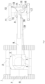
- a specific embodiment of a 3D printing device as shown in Figs. 1-4 includes a control structure including a control chamber 3 and an arm lever 8, a printing structure disposed on an end of the arm lever 8 away from the control chamber 3, a walking structure 2 disposed below the control chamber 3, and a power structure disposed at an end of the control chamber 3 facing away from the arm lever 8.
- the arm lever 8 is provided as a multi-section boom. The relative rotation between the multiple sections of the boom is ensured by means of pins and bearings, and the relative rotation between the adjacent sections of the boom is achieved by oil cylinders or steel wire ropes.
- the printing structure includes a print carriage, and a nozzle 16 disposed on the print carriage.
- an angle adjusting member is disposed on the print carriage.
- the angle adjusting member is a spherical plain bearing.
- a slewing structure is disposed between the print carriage and the arm lever 8, and includes a planetary gear 9 disposed on the arm lever 8, a slewing gear 10 disposed on the print carriage, and a slewing power member for driving the planetary gear to rotate, wherein the planetary gear 9 is meshed with the slewing gear 10.
- the slewing power member is preferably a servo motor or other appropriate types of motors.
- the print carriage includes at least two transverse beams 15 and two longitudinal beams 11.
- the transverse beams 15 and the longitudinal beams 11 enclose a truss.
- Transverse power members 13 are disposed on the transverse beams 15, and longitudinal power members are disposed on the longitudinal beams 11.
- the transverse power members 13 drive the nozzle 16 to move transversely, and the longitudinal power members drive the transverse beams 15 to move longitudinally.
- the transverse power members 13 and the longitudinal power members are preferably servo motors or other appropriate types of motors.
- a reinforcing rib 17 is disposed at the connection position of the transverse beams 15 and the arm lever 8.
- two ends of each longitudinal beam 11 are respectively provided with at least one adjustable leg 12 that is used to adjust the relative height and angle of the print carriage to the ground, such that the print carriage can adapt to to-be-printed concrete models in different shapes and at different angles, to meet different construction needs.
- the leg 12 is a hydraulically stretchable leg.
- the leg 12 may also provide good support for the print carriage, which avoids impacting printing quality during printing due to feeding or vibration, and ensures that the print carriage is parallel to or forms a preset angle with the surface of to-be-printed concrete, thereby printing planar or curved concrete, and ensuring printing quality.
- an end of the arm lever 8 close to the print carriage is provided with a camera 18 that is disposed towards a spraying direction of the nozzle 16.
- a plurality of altimeters 22 are also disposed on a circumferential side wall of the nozzle 16.
- the respective altimeters 22 measure the heights of the ground and the heights of printed concrete in different directions, and data is fed back to the control chamber 3 for comparison to confirm actual heights of individual points that need to be printed on the uneven ground and whether the height of the printed concrete meets the design requirements.
- a spray power member 20 is disposed at the nozzle 16.
- the spray power member 20 is preferably a servo motor or other appropriate types of motors.
- the 3D printing device further includes an angle meter.
- the nozzle yaw power member 31 drives a nozzle yaw power shaft 32 to rotate in a yaw fixed shaft sleeve 28, and the nozzle yaw power shaft 32 is fixedly connected to a yaw movable sleeve 29 that is fixedly connected to a nozzle support 30 and the nozzle and associated mechanisms below the nozzle support 30.
- the nozzle yaw power shaft 32 drives the nozzle support 30 and the nozzle 16 to swing when in rotation.
- the angle rotating member 26 is fixed onto a nozzle base 25 by a nozzle base support 24.
- the nozzle base 25 drives the nozzle and associated mechanisms to slide linearly on the transverse beams 15 and rails.
- the angle rotating member 26 drives a rotating shaft support 23 and the nozzle 16 below the rotating shaft support 23 to rotate while driving a rotating shaft 27 to rotate, thereby implementing movement of the nozzle in respective dimensions.
- a controller is disposed in the control chamber 3, wherein the controller is in communication connection with the slewing power member, the transverse power members 13, the longitudinal power members, the spray power member 20, the nozzle yaw power member 31, the angle rotating member 26, the camera 18, the altimeters 22, the angle meter, the nozzle 16 and the legs 12, respectively.
- connecting lines 14 pass through holes in the angle adjusting member to be connected to structures of various parts of the print carriage. To print different trajectories, patterns of grid beams, ramp angles, cross sections of grid beams or the like are set in a preset program in the controller, and three-dimensional simulated grid beams are preset in the controller.
- Parameters such as coordinates of a to-be-printed ramp region, an inclination angle, etc., are input into the controller before printing, and the pattern of a to-be-printed grid beam is selected in the control program. If there is no pattern of the to-be-printed grid beam in a pattern library, a new pattern of the grid beam is formed by setting specific parameters.
- the 3D printing device further includes a power structure that is disposed at an end of the control chamber 3 away from the arm lever 8.
- the power structure includes an actuator 6 and a counterweight case 7, wherein the actuator 6 is in communication connection with the controller to achieve multi-structure ganged control by the controller. It should be noted that modifications can be made on the basis of existing mature construction equipment platforms, such that the power structure provides power for the entire device.
- the 3D printing device further includes a feeding structure that includes a concrete tank 5, a delivery pump 4 and a feeding tube 19.
- the concrete tank 5 and the delivery pump 4 are disposed on the side surface of the control chamber 3.
- the feeding tube 19 is disposed at an output end of the delivery pump 4, goes by the arm lever 8 and then is in pipeline connection with a material inlet 21 the nozzle 16.
- the delivery pump 4 is in communication connection with the controller. Specifically, the delivery pump 4 is a screw pump.
- on-site personnel operates the controller in the control chamber 3 to control caterpillar bands 1 of the walking structure 2 to a to-be-printed position, and to control an arm head to extend to the to-be-printed ground which is divided into a plurality of to-be-printed regions.
- a long-side printing manner, a short-side printing manner or an oblique printing manner is selected by rotating the print carriage by the slewing power member according to a size and a length-width ratio of the to-be-printed region, thereby adapting to ramps in various angles and ramp concrete in various patterns and shapes.
- An initial print sideline is preset in the controller, one side of the print carriage is selected to be aligned with the initial print sideline, and a program can automatically control the print carriage to move to be aligned with the initial print sideline.
- the on-site personnel observes video signals captured by the camera 18 and stops the rotation of the print carriage after the edge of the print carriage is aligned with the line of the to-be-printed region, and the controller plans printing lines.
- the legs 12 at four corners of the print carriage extend out.
- the control system controls the legs 12 at four corners to extend by respective calculated lengths by measurement made by the altimeters 22 disposed on the print carriage, so as to adjust the print carriage to be parallel to or to form the preset angle with the ground where concrete is to be printed, thereby printing planar or curved concrete.
- the spherical plain bearing at the connection position of the arm lever 8 and the print carriage performs rotation and adaptive adjustment under the retroaction of the supporting force of oil cylinders of the legs 12 to the ground, thereby achieving the adaptive leveling of the angle of the print carriage.
- Such a structure design is simple, efficient and practical, without the need of design and installation of a multi-dimensional adjustment mechanism at the spherical plain bearing.
- a plurality of altimeters 22 prearranged on the print carriage are used to make an overall height measurement of the ground within the region of the print carriage at this time. Data is transmitted to the control system for comparison to confirm actual heights of individual points that need to be printed on the uneven ground.
- the compassion is performed with the height of concrete that needs to be printed at this point and is preset by the system after detection, and then whether the height of the printed concrete meets design requirements is determined and corrected. It is thereby ensured that the printed concrete surfaces are at the same height in the case of printing of the uneven ground, or curved concrete with unequal heights is printed according to the preset requirements.
- the controller After preparation, the controller starts the delivery pump 4, and drives the transverse beam 15 power members and the longitudinal beam 11 power members to move to drive the nozzle 16 to spray concrete slurry according to a previously planned path for printing. Meanwhile, the altimeters 22 perform height measurement, and the measured data is transmitted to the controller for comparison to confirm the concave-convex shape of the surfaces at different positions on the ground.
- the print carriage remains parallel to or forms a preset angle with the surface of the to-be-printed concrete, thereby controlling the nozzle 16 to spray concrete slurry with different flow rates, and controlling the legs 12 to be slightly stretch to ensure an optimal spraying angle of the nozzle 16.
- the print carriage repeats the above cycle after being aligned with the alignment line preset in the system or aligned with an edge of a last concrete module printed, and reciprocates until the entire printing operation of the to-be-printed ground is finished.
- the three-dimensional simulated grid preset in the controller is automatically fitted with the grid beam captured by the camera to perform prompt when differences occur, and correction, making up and improvement are performed for subsequent printing.
- a control system includes a device movement platform control system, a feeding control system, a printing control system, and the like.
- the control system can perform on-site control, or perform remote control.
- the control system performs organizational control on the device movement platform control system, the feeding control system and the printing control system through advanced design, built-in software and hardware planning.
- an angle value of the print carriage measured by the angle meter is transferred to the controller during printing, the individual legs 12 of the print carriage are adjusted to extend by unequal lengths based on the values calculated by the controller, and stretch by different lengths rapidly at the individual points based on the pre-planned path on the premise of continuous printing, such that an angle is formed between the print carriage and the to-be-printed printed ground, and thus an unequal-height space is reserved for the printed concrete, thereby facilitating the printing of the curved or ramp concrete.
- the legs 12 may provide reliable support of the print carriage, which prevents the printing quality from being affected by the vibrations caused by feeding and printing in the printing process, thereby ensuring the printing quality.
- the angle adjusting member at the connection position of the arm lever and the print carriage performs rotation and adaptive adjustment under the retroaction of the supporting force of the legs 12 to the ground, thereby achieving the adaptive leveling of the angle of the print carriage.
- the angle adjusting member has the advantages of simplicity, efficiency and practicability, without the need of design and installation of a multi-dimensional adjustment mechanism.
- the printing device can print grid beams in varying shapes, for example, regular grid beams having a uniform cross section shape or non-regular grid beams all can be printed well.
- the multi-functional concrete 3D printing device provided by the present invention has the following advantages: (1) With the parallelism measurement and adjustment system, the problem of low 3D printing accuracy is solved by the connection of the legs 12, the altimeters 22 and the controller, and high-accuracy printing is achieved, so that the quality of the concrete print is guaranteed. (2) The degree of automation is high. With the collaborative work of the individual structures from 3D printed concrete production to precise positioning of the print, the controller plans the print path of the model in advance to perform dynamic adjustment in printing different concrete structures so as to achieve automation, and also controls the spraying amount of concrete slurry from the nozzle 16 based on the heights measured the altimeters 22. (3) The versatility is strong. The 3D printing device is applicable to printing of concrete models in different shapes.
- the overall structure is compact and simple.
- the 3D printing device can adapt to different work platforms and sites, read relevant printing data in real time, is located at relevant positions, and has abundant structures and functions.
- the working efficiency is high: the cooperative work of the print carriage and the controller is achieved to improve the working quality; and the print carriage freely moves in the printing region, so that the working efficiency is obviously improved.
- a positioner reads the relevant data of the printing region in real time to ensure the printing effect.
- the angle adjusting member may also be a round ball.
- the delivery pump 4 may also be a gear pump or other types of pumps.
- the legs 12 are in other stretchable forms, such as barometric stretchable legs, and the legs 12 may also be manually adjusted.
- the print carriage may also be subjected to manual printing under the control of the operator.
- four sides of the print carriage may also be provided with a print alignment line, and the position the print alignment line is photographed by the camera, and is transferred to the controller.
- An observer observes or a display screen in the control chamber shows the positions of the print alignment line and a reference print boundary, and enables the print alignment line to be aligned with the reference print boundary, thereby ensuring the alignment and proper engagement between concrete printed each time.
- the 3D printing device is applicable to numerous banded concrete printing, such as concrete grid beams, concrete barriers, concrete enclosures, etc., in various types of engineering construction projects with complex terrain conditions, is an intelligent, automated, economical 3D printing system with high accuracy and environmental adaptability for the above printing.
- the applicability and practicability of the device are comprehensively improved to achieve the working efficiency of 3D concrete printing under complex geographical conditions by the connection of the boom structure and the nozzle with the slewing and bi-directional movement mechanisms with assistance of the height measurement and calibration device and the corresponding control system.
Landscapes
- Engineering & Computer Science (AREA)
- Chemical & Material Sciences (AREA)
- Manufacturing & Machinery (AREA)
- Mechanical Engineering (AREA)
- Materials Engineering (AREA)
- Ceramic Engineering (AREA)
- Robotics (AREA)
- Architecture (AREA)
- Structural Engineering (AREA)
- Civil Engineering (AREA)
- Lining And Supports For Tunnels (AREA)
- Ink Jet (AREA)
- Coating Apparatus (AREA)
Claims (7)
- A multifunktionale Beton 3D Druckvorrichtung, bestehend aus:eine Steuerstruktur, bestehend aus einer Steuerkammer (3) und Armhebeln (8), wobei die relative Rotation zwischen den Armhebeln (8) durch Stifte und Lager sichergestellt wird, die Relativbewegung zwischen den Armhebeln (8) durch Ölzylinder oder Stahlseile erreicht wird und eine Steuerung der Steuerkammer (3) in Übertragungsverbindung mit den Armhebeln (8) zur Steuerung der Wirkung der Armhebel (8) steht; undeine Druckkonstruktion, die an einem Ende der Armhebel (8) von der Steuerkammer entfemt angeordnet ist (3), mit dem Armhebel (8) am Ende dieser Armhebel (8) verbunden ist,und bestehend aus einem Druckwagen, einer Düse (16), die auf dem Druckwagen angeordnet ist, und mindestens einem verstellbaren Bein (12), das auf dem Druckwagen angeordnet ist, wobei zwischen dem Druckwagen und dem Armhebel ein Winkelverstellelement angeordnet ist (8), die Düse (16) mit einem Winkeldrehelement (26) und einem Düsen-Gier-Antriebselement (31) versehen ist, steuert die Steuerung die Verlängerungslänge des Beins (12), um das Winkeleinstellelement zu veranlassen, den Druckwagen zu drehen, und die Düse (16) sprüht aus verschiedenen Winkeln durch Drehen des Druckwagens, Drehen und Drehen des Giers (31) und Drehen des Druckteils aus verschiedenen Winkeln;Dadurch gekennzeichnet, dass zwischen dem Druckwagen und dem Armhebel (8) eine Schwenkstruktur angeordnet ist und ein auf dem Druckwagen angeordnetes Planetengetriebe (9) und ein auf dem Druckwagen angeordnetes Schwenkgetriebe (10) umfasst, wobei das Planetengetriebe (9) mit dem Schwenkgetriebe (10) verzahnt ist und die Schwenkstruktur in Kommunikationsverbindung mit der Steuerung steht.
- Die multifunktionale Beton-3D-Druckvorrichtung des Anspruchs 1, dadurch gekennzeichnet, dass das Winkeleinstellelement ein Kugelgleitlager ist.
- Die multifunktionale Beton-3D-Druckvorrichtung des Anspruchs 1, dadurch gekennzeichnet, dass eine Seitenwand der Düse (16) fest mit einem Höhenmesser versehen ist, der in Kommunikationsverbindung mit der Steuerung steht.
- Die multifunktionale Beton-3D-Druckvorrichtung des Anspruchs 1, dadurch gekennzeichnet, dass der Druckwagen mindestens zwei Querträger (15) und zwei Längsträger (11) umfasst und mit einer Kamera (18) und der Düse (16) versehen ist; die Querträger (15) und die Längsträger (11) umschließen einen Fachwerk; Querkraftträger (13) sind auf den Querträgem angeordnet (15), Längsleistungsteile auf den Längsträgem (11); die Kamera (18) in Spritzrichtung der Düse angeordnet ist (16), und die Steuerung ist in Kommunikationsverbindung mit der Kamera (18); Raupenbänder oder Gleitschienen sind auf den Querträgem (15) und den Längsträgem (11) gepflastert; und die Querleistungsglieder (13) und die Längsleistungsteile sind jeweils in Kommunikationsverbindung mit der Steuerung.
- Die multifunktionale Beton-3D-Druckvorrichtung des Anspruchs 1, gekennzeichnet durch eine Zuführstruktur, die einen Betontank (5), eine Förderpumpe (4) und ein Zufü hrrohr (19) umfasst, wobei der Betontank (5) und die Förderpumpe (4) auf einer Seitenfläche der Steuerkammer angeordnet sind (3); Das Förderrohr (19) wird am Ausgang der Förderpumpe (4) angeordnet, geht über den Armhebel (8) und wird dann mit der D ü se (16) verbunden; und die Förderpumpe (4) ist in Kommunikationsverbindung mit der Steuerung.
- Die multifunktionale Beton-3D-Druckvorrichtung gemäß Anspruch 5, gekennzeichnet durch eine Kraftstruktur, die an einem Ende der Steuerkammer (3) angeordnet ist, weg vom Armhebel (8), und eine Laufstruktur (2), die unterhalb der Steuerkammer angeordnet ist, wobei die Kraftstruktur einen Aktuator (6) und einen Gegengewichtskoffer (7) umfasst; und die Laufkonstruktion (2) ist drehbar mit der Kontrollkammer verbunden (3).
- Die multifunktionale Beton-3D-Druckvorrichtung des Anspruchs 6, gekennzeichnet durch eine Düsen-Gier-Antriebswelle (32), die durch das Düsen-Gier-Antriebselement (31) angetrieben wird, um in einer Gier-festen Wellenhülse zu drehen (28), wobei die Düsen-Gier-Antriebswelle (32) fest mit einer Gier-beweglichen Hülse verbunden ist (29), die Gier-bewegliche Hülse (29) fest mit einer Düsenstütze (30) und die Düse unterhalb der Düsenstütze (30) verbunden ist; die Düsenantriebswelle (32) treibt die D ü senst ü tze (30) und die Düse (16) bei Rotation zum Schwingen an; das Winkeldrehelement (26) wird durch eine Düsenbasis (24) auf einem Düsenbasis (25) befestigt; der Düsenboden (25) treibt die Düse und die zugehörigen Mechanismen linear auf den Querträgem an (15); Das Winkeldrehelement (26) treibt eine rotierende Wellenstütze (23) und die Düse (16) unterhalb der rotierenden Wellenstütze (23) an, um sich während des Antriebes einer rotierenden Welle (27) zu drehen, wodurch Bewegung der Düse in den jeweiligen Abmessungen realisiert wird.
Applications Claiming Priority (1)
| Application Number | Priority Date | Filing Date | Title |
|---|---|---|---|
| CN202310099824.8A CN116352845B (zh) | 2023-02-03 | 2023-02-03 | 一种多功能型混凝土3d打印设备及使用方法 |
Publications (2)
| Publication Number | Publication Date |
|---|---|
| EP4411073A1 EP4411073A1 (de) | 2024-08-07 |
| EP4411073B1 true EP4411073B1 (de) | 2025-05-28 |
Family
ID=86007287
Family Applications (1)
| Application Number | Title | Priority Date | Filing Date |
|---|---|---|---|
| EP23167663.6A Active EP4411073B1 (de) | 2023-02-03 | 2023-04-13 | Multifunktionale beton-3d-druckvorrichtung |
Country Status (2)
| Country | Link |
|---|---|
| EP (1) | EP4411073B1 (de) |
| CN (1) | CN116352845B (de) |
Families Citing this family (4)
| Publication number | Priority date | Publication date | Assignee | Title |
|---|---|---|---|---|
| CN116852488B (zh) * | 2023-08-03 | 2026-01-30 | 中国长江三峡集团有限公司 | 一种混凝土3d打印设备及其使用方法 |
| DE102023124619A1 (de) * | 2023-09-12 | 2025-03-13 | Schwing Gmbh | Großmanipulator und Verfahren zur Steuerung eines Großmanipulators |
| CN120231431B (zh) * | 2025-05-29 | 2025-09-19 | 深圳大学 | 3d打印混凝土界面加固方法及系统 |
| CN120440100B (zh) * | 2025-07-09 | 2025-09-12 | 山西建筑工程集团有限公司 | 一种建筑工程流体材料用清理装置 |
Family Cites Families (9)
| Publication number | Priority date | Publication date | Assignee | Title |
|---|---|---|---|---|
| KR101914524B1 (ko) * | 2017-01-19 | 2018-11-02 | 연세대학교 산학협력단 | 모바일 콘크리트 건축물 3d 프린팅 시스템 |
| US10920434B1 (en) * | 2017-06-23 | 2021-02-16 | Kent Douglas Pearson, Jr. | Portable robotic construction system |
| CN108755934A (zh) * | 2018-05-21 | 2018-11-06 | 天津依蓝时代电气设备有限公司 | 房屋的3d打印方法 |
| US11220041B2 (en) * | 2018-08-08 | 2022-01-11 | Anna CHEN-IUN-TAI | 3-D printing at inclined angles |
| JP7303767B2 (ja) * | 2020-03-12 | 2023-07-05 | 株式会社熊谷組 | 構造物施工装置および構造物施工方法 |
| CN213062969U (zh) * | 2020-08-19 | 2021-04-27 | 北京美斯顿科技开发有限公司 | 建筑3d打印设备 |
| IT202100010091A1 (it) * | 2021-04-21 | 2022-10-21 | Paolo Garetti | Sistema per la realizzazione di un prodotto cementizio |
| CN113605704B (zh) * | 2021-08-30 | 2022-11-04 | 杭州冠力智能科技有限公司 | 一种可移动式混凝土3d打印装置及其施工方法 |
| CN115142395B (zh) * | 2022-06-24 | 2024-09-20 | 河北工业大学 | 一种废弃矿山微地形改造装备 |
-
2023
- 2023-02-03 CN CN202310099824.8A patent/CN116352845B/zh active Active
- 2023-04-13 EP EP23167663.6A patent/EP4411073B1/de active Active
Also Published As
| Publication number | Publication date |
|---|---|
| CN116352845A (zh) | 2023-06-30 |
| EP4411073A1 (de) | 2024-08-07 |
| CN116352845B (zh) | 2025-08-01 |
Similar Documents
| Publication | Publication Date | Title |
|---|---|---|
| EP4411073A1 (de) | Multifunktionale beton-3d-druckvorrichtung und verwendungsverfahren | |
| CN111070387B (zh) | 预制梁体模板自动精密调整装置、方法及系统 | |
| CN113646136B (zh) | 缆索机器人 | |
| RU2690436C2 (ru) | Устройство и способ для послойного изготовления трехмерных конструкций | |
| US9708780B1 (en) | Track drive apparatus for screeding concrete | |
| CN112012450A (zh) | 一种自动抹灰机 | |
| JP7400391B2 (ja) | 型枠装置及び型枠自動設置システム | |
| CN121047416A (zh) | 一种大面积混凝土浇筑振捣与找平装置及使用方法 | |
| CN118979448A (zh) | 一种智能自动纠偏钢梁顶推系统 | |
| CN120193522A (zh) | 一种预埋式格构柱动态调正调直装置及其施工方法 | |
| CN116141510B (zh) | 一种多自由度联动式凿毛机 | |
| JP7364185B2 (ja) | 支保工建込方法および支保工建込システム | |
| JP4960145B2 (ja) | 均し装置 | |
| KR102309917B1 (ko) | 축조물 자동 시공 시스템 | |
| JP7080689B2 (ja) | 構造物の補修装置、及び補修方法 | |
| JP4359909B2 (ja) | スリップフォーム工法における型枠上昇制御方法 | |
| JPH08142034A (ja) | ショートラインマッチキャスティング用型枠自動制御システム | |
| CN115522553B (zh) | 一种基于图像识别的基坑锚杆无人钻孔施工系统及方法 | |
| JP2745004B2 (ja) | 鉄骨建方法 | |
| JP7736447B2 (ja) | 吹付けシステムおよび吹付け方法 | |
| US12516529B2 (en) | Machine for treating a concrete surface | |
| CN223256453U (zh) | 一种用于倾斜楼面的支撑架底座结构 | |
| JP2022029535A (ja) | 鋼製支保工建て込み時の遠隔操作式ボルト締結装置 | |
| CN112443160A (zh) | 一种布料-整平-抹平一体化自动作业机器人装备 | |
| JP7667028B2 (ja) | ポンプ設備の中間体、ポンプ設備の製造方法およびポンプ設備の少なくとも一部を位置合わせする方法 |
Legal Events
| Date | Code | Title | Description |
|---|---|---|---|
| PUAI | Public reference made under article 153(3) epc to a published international application that has entered the european phase |
Free format text: ORIGINAL CODE: 0009012 |
|
| STAA | Information on the status of an ep patent application or granted ep patent |
Free format text: STATUS: REQUEST FOR EXAMINATION WAS MADE |
|
| 17P | Request for examination filed |
Effective date: 20230508 |
|
| AK | Designated contracting states |
Kind code of ref document: A1 Designated state(s): AL AT BE BG CH CY CZ DE DK EE ES FI FR GB GR HR HU IE IS IT LI LT LU LV MC ME MK MT NL NO PL PT RO RS SE SI SK SM TR |
|
| RBV | Designated contracting states (corrected) |
Designated state(s): AL AT BE BG CH CY CZ DE DK EE ES FI FR GB GR HR HU IE IS IT LI LT LU LV MC ME MK MT NL NO PL PT RO RS SE SI SK SM TR |
|
| RIC1 | Information provided on ipc code assigned before grant |
Ipc: E04G 21/04 20060101ALN20241122BHEP Ipc: E02D 17/20 20060101ALI20241122BHEP Ipc: B25J 19/00 20060101ALI20241122BHEP Ipc: B25J 5/00 20060101ALI20241122BHEP Ipc: E02B 3/12 20060101ALI20241122BHEP Ipc: B28B 1/00 20060101ALI20241122BHEP Ipc: B62D 57/02 20060101ALI20241122BHEP Ipc: B33Y 30/00 20150101ALI20241122BHEP Ipc: B33Y 10/00 20150101ALI20241122BHEP Ipc: B25J 9/00 20060101ALI20241122BHEP Ipc: E02D 17/18 20060101ALI20241122BHEP Ipc: E02D 17/00 20060101AFI20241122BHEP |
|
| GRAP | Despatch of communication of intention to grant a patent |
Free format text: ORIGINAL CODE: EPIDOSNIGR1 |
|
| STAA | Information on the status of an ep patent application or granted ep patent |
Free format text: STATUS: GRANT OF PATENT IS INTENDED |
|
| RIC1 | Information provided on ipc code assigned before grant |
Ipc: E04G 21/04 20060101ALN20241217BHEP Ipc: E02D 17/20 20060101ALI20241217BHEP Ipc: B25J 19/00 20060101ALI20241217BHEP Ipc: B25J 5/00 20060101ALI20241217BHEP Ipc: E02B 3/12 20060101ALI20241217BHEP Ipc: B28B 1/00 20060101ALI20241217BHEP Ipc: B62D 57/02 20060101ALI20241217BHEP Ipc: B33Y 30/00 20150101ALI20241217BHEP Ipc: B33Y 10/00 20150101ALI20241217BHEP Ipc: B25J 9/00 20060101ALI20241217BHEP Ipc: E02D 17/18 20060101ALI20241217BHEP Ipc: E02D 17/00 20060101AFI20241217BHEP |
|
| INTG | Intention to grant announced |
Effective date: 20250107 |
|
| GRAS | Grant fee paid |
Free format text: ORIGINAL CODE: EPIDOSNIGR3 |
|
| GRAA | (expected) grant |
Free format text: ORIGINAL CODE: 0009210 |
|
| STAA | Information on the status of an ep patent application or granted ep patent |
Free format text: STATUS: THE PATENT HAS BEEN GRANTED |
|
| AK | Designated contracting states |
Kind code of ref document: B1 Designated state(s): AL AT BE BG CH CY CZ DE DK EE ES FI FR GB GR HR HU IE IS IT LI LT LU LV MC ME MK MT NL NO PL PT RO RS SE SI SK SM TR |
|
| REG | Reference to a national code |
Ref country code: GB Ref legal event code: FG4D |
|
| REG | Reference to a national code |
Ref country code: CH Ref legal event code: EP |
|
| REG | Reference to a national code |
Ref country code: IE Ref legal event code: FG4D Ref country code: DE Ref legal event code: R096 Ref document number: 602023003666 Country of ref document: DE |
|
| REG | Reference to a national code |
Ref country code: NL Ref legal event code: MP Effective date: 20250528 |
|
| PG25 | Lapsed in a contracting state [announced via postgrant information from national office to epo] |
Ref country code: FI Free format text: LAPSE BECAUSE OF FAILURE TO SUBMIT A TRANSLATION OF THE DESCRIPTION OR TO PAY THE FEE WITHIN THE PRESCRIBED TIME-LIMIT Effective date: 20250528 Ref country code: ES Free format text: LAPSE BECAUSE OF FAILURE TO SUBMIT A TRANSLATION OF THE DESCRIPTION OR TO PAY THE FEE WITHIN THE PRESCRIBED TIME-LIMIT Effective date: 20250528 |
|
| REG | Reference to a national code |
Ref country code: LT Ref legal event code: MG9D |
|
| PG25 | Lapsed in a contracting state [announced via postgrant information from national office to epo] |
Ref country code: GR Free format text: LAPSE BECAUSE OF FAILURE TO SUBMIT A TRANSLATION OF THE DESCRIPTION OR TO PAY THE FEE WITHIN THE PRESCRIBED TIME-LIMIT Effective date: 20250829 Ref country code: NO Free format text: LAPSE BECAUSE OF FAILURE TO SUBMIT A TRANSLATION OF THE DESCRIPTION OR TO PAY THE FEE WITHIN THE PRESCRIBED TIME-LIMIT Effective date: 20250828 |
|
| PG25 | Lapsed in a contracting state [announced via postgrant information from national office to epo] |
Ref country code: NL Free format text: LAPSE BECAUSE OF FAILURE TO SUBMIT A TRANSLATION OF THE DESCRIPTION OR TO PAY THE FEE WITHIN THE PRESCRIBED TIME-LIMIT Effective date: 20250528 Ref country code: PL Free format text: LAPSE BECAUSE OF FAILURE TO SUBMIT A TRANSLATION OF THE DESCRIPTION OR TO PAY THE FEE WITHIN THE PRESCRIBED TIME-LIMIT Effective date: 20250528 |
|
| PG25 | Lapsed in a contracting state [announced via postgrant information from national office to epo] |
Ref country code: BG Free format text: LAPSE BECAUSE OF FAILURE TO SUBMIT A TRANSLATION OF THE DESCRIPTION OR TO PAY THE FEE WITHIN THE PRESCRIBED TIME-LIMIT Effective date: 20250528 |
|
| PG25 | Lapsed in a contracting state [announced via postgrant information from national office to epo] |
Ref country code: HR Free format text: LAPSE BECAUSE OF FAILURE TO SUBMIT A TRANSLATION OF THE DESCRIPTION OR TO PAY THE FEE WITHIN THE PRESCRIBED TIME-LIMIT Effective date: 20250528 |
|
| PG25 | Lapsed in a contracting state [announced via postgrant information from national office to epo] |
Ref country code: RS Free format text: LAPSE BECAUSE OF FAILURE TO SUBMIT A TRANSLATION OF THE DESCRIPTION OR TO PAY THE FEE WITHIN THE PRESCRIBED TIME-LIMIT Effective date: 20250828 |
|
| PG25 | Lapsed in a contracting state [announced via postgrant information from national office to epo] |
Ref country code: IS Free format text: LAPSE BECAUSE OF FAILURE TO SUBMIT A TRANSLATION OF THE DESCRIPTION OR TO PAY THE FEE WITHIN THE PRESCRIBED TIME-LIMIT Effective date: 20250928 |
|
| PG25 | Lapsed in a contracting state [announced via postgrant information from national office to epo] |
Ref country code: LV Free format text: LAPSE BECAUSE OF FAILURE TO SUBMIT A TRANSLATION OF THE DESCRIPTION OR TO PAY THE FEE WITHIN THE PRESCRIBED TIME-LIMIT Effective date: 20250528 |
|
| REG | Reference to a national code |
Ref country code: AT Ref legal event code: MK05 Ref document number: 1798672 Country of ref document: AT Kind code of ref document: T Effective date: 20250528 |
|
| PG25 | Lapsed in a contracting state [announced via postgrant information from national office to epo] |
Ref country code: DK Free format text: LAPSE BECAUSE OF FAILURE TO SUBMIT A TRANSLATION OF THE DESCRIPTION OR TO PAY THE FEE WITHIN THE PRESCRIBED TIME-LIMIT Effective date: 20250528 Ref country code: AT Free format text: LAPSE BECAUSE OF FAILURE TO SUBMIT A TRANSLATION OF THE DESCRIPTION OR TO PAY THE FEE WITHIN THE PRESCRIBED TIME-LIMIT Effective date: 20250528 Ref country code: SM Free format text: LAPSE BECAUSE OF FAILURE TO SUBMIT A TRANSLATION OF THE DESCRIPTION OR TO PAY THE FEE WITHIN THE PRESCRIBED TIME-LIMIT Effective date: 20250528 |
|
| PG25 | Lapsed in a contracting state [announced via postgrant information from national office to epo] |
Ref country code: CZ Free format text: LAPSE BECAUSE OF FAILURE TO SUBMIT A TRANSLATION OF THE DESCRIPTION OR TO PAY THE FEE WITHIN THE PRESCRIBED TIME-LIMIT Effective date: 20250528 |
|
| PG25 | Lapsed in a contracting state [announced via postgrant information from national office to epo] |
Ref country code: EE Free format text: LAPSE BECAUSE OF FAILURE TO SUBMIT A TRANSLATION OF THE DESCRIPTION OR TO PAY THE FEE WITHIN THE PRESCRIBED TIME-LIMIT Effective date: 20250528 |
|
| PG25 | Lapsed in a contracting state [announced via postgrant information from national office to epo] |
Ref country code: SK Free format text: LAPSE BECAUSE OF FAILURE TO SUBMIT A TRANSLATION OF THE DESCRIPTION OR TO PAY THE FEE WITHIN THE PRESCRIBED TIME-LIMIT Effective date: 20250528 |
|
| PG25 | Lapsed in a contracting state [announced via postgrant information from national office to epo] |
Ref country code: IT Free format text: LAPSE BECAUSE OF FAILURE TO SUBMIT A TRANSLATION OF THE DESCRIPTION OR TO PAY THE FEE WITHIN THE PRESCRIBED TIME-LIMIT Effective date: 20250528 |
|
| REG | Reference to a national code |
Ref country code: DE Ref legal event code: R097 Ref document number: 602023003666 Country of ref document: DE |
|
| PLBE | No opposition filed within time limit |
Free format text: ORIGINAL CODE: 0009261 |
|
| STAA | Information on the status of an ep patent application or granted ep patent |
Free format text: STATUS: NO OPPOSITION FILED WITHIN TIME LIMIT |
|
| REG | Reference to a national code |
Ref country code: CH Ref legal event code: L10 Free format text: ST27 STATUS EVENT CODE: U-0-0-L10-L00 (AS PROVIDED BY THE NATIONAL OFFICE) Effective date: 20260409 |
|
| 26N | No opposition filed |
Effective date: 20260303 |