EP4411056A1 - Combination laundry appliance with heat pump assembly - Google Patents
Combination laundry appliance with heat pump assembly Download PDFInfo
- Publication number
- EP4411056A1 EP4411056A1 EP24154719.9A EP24154719A EP4411056A1 EP 4411056 A1 EP4411056 A1 EP 4411056A1 EP 24154719 A EP24154719 A EP 24154719A EP 4411056 A1 EP4411056 A1 EP 4411056A1
- Authority
- EP
- European Patent Office
- Prior art keywords
- condenser
- wash
- cycle
- heat
- refrigerant
- Prior art date
- Legal status (The legal status is an assumption and is not a legal conclusion. Google has not performed a legal analysis and makes no representation as to the accuracy of the status listed.)
- Withdrawn
Links
Images


Classifications
-
- D—TEXTILES; PAPER
- D06—TREATMENT OF TEXTILES OR THE LIKE; LAUNDERING; FLEXIBLE MATERIALS NOT OTHERWISE PROVIDED FOR
- D06F—LAUNDERING, DRYING, IRONING, PRESSING OR FOLDING TEXTILE ARTICLES
- D06F25/00—Washing machines with receptacles, e.g. perforated, having a rotary movement, e.g. oscillatory movement, the receptacle serving both for washing and for centrifugally separating water from the laundry and having further drying means, e.g. using hot air
-
- D—TEXTILES; PAPER
- D06—TREATMENT OF TEXTILES OR THE LIKE; LAUNDERING; FLEXIBLE MATERIALS NOT OTHERWISE PROVIDED FOR
- D06F—LAUNDERING, DRYING, IRONING, PRESSING OR FOLDING TEXTILE ARTICLES
- D06F33/00—Control of operations performed in washing machines or washer-dryers
- D06F33/50—Control of washer-dryers characterised by the purpose or target of the control
- D06F33/52—Control of the operational steps, e.g. optimisation or improvement of operational steps depending on the condition of the laundry
- D06F33/56—Control of the operational steps, e.g. optimisation or improvement of operational steps depending on the condition of the laundry of washing
-
- D—TEXTILES; PAPER
- D06—TREATMENT OF TEXTILES OR THE LIKE; LAUNDERING; FLEXIBLE MATERIALS NOT OTHERWISE PROVIDED FOR
- D06F—LAUNDERING, DRYING, IRONING, PRESSING OR FOLDING TEXTILE ARTICLES
- D06F33/00—Control of operations performed in washing machines or washer-dryers
- D06F33/50—Control of washer-dryers characterised by the purpose or target of the control
- D06F33/70—Control of the operating time, e.g. reduction of overall operating time
-
- D—TEXTILES; PAPER
- D06—TREATMENT OF TEXTILES OR THE LIKE; LAUNDERING; FLEXIBLE MATERIALS NOT OTHERWISE PROVIDED FOR
- D06F—LAUNDERING, DRYING, IRONING, PRESSING OR FOLDING TEXTILE ARTICLES
- D06F39/00—Details of washing machines not specific to a single type of machines covered by groups D06F9/00 - D06F27/00
- D06F39/04—Heating arrangements
-
- D—TEXTILES; PAPER
- D06—TREATMENT OF TEXTILES OR THE LIKE; LAUNDERING; FLEXIBLE MATERIALS NOT OTHERWISE PROVIDED FOR
- D06F—LAUNDERING, DRYING, IRONING, PRESSING OR FOLDING TEXTILE ARTICLES
- D06F39/00—Details of washing machines not specific to a single type of machines covered by groups D06F9/00 - D06F27/00
- D06F39/08—Liquid supply or discharge arrangements
- D06F39/083—Liquid discharge or recirculation arrangements
- D06F39/085—Arrangements or adaptations of pumps
-
- D—TEXTILES; PAPER
- D06—TREATMENT OF TEXTILES OR THE LIKE; LAUNDERING; FLEXIBLE MATERIALS NOT OTHERWISE PROVIDED FOR
- D06F—LAUNDERING, DRYING, IRONING, PRESSING OR FOLDING TEXTILE ARTICLES
- D06F58/00—Domestic laundry dryers
- D06F58/20—General details of domestic laundry dryers
- D06F58/206—Heat pump arrangements
-
- D—TEXTILES; PAPER
- D06—TREATMENT OF TEXTILES OR THE LIKE; LAUNDERING; FLEXIBLE MATERIALS NOT OTHERWISE PROVIDED FOR
- D06F—LAUNDERING, DRYING, IRONING, PRESSING OR FOLDING TEXTILE ARTICLES
- D06F58/00—Domestic laundry dryers
- D06F58/20—General details of domestic laundry dryers
- D06F58/24—Condensing arrangements
-
- D—TEXTILES; PAPER
- D06—TREATMENT OF TEXTILES OR THE LIKE; LAUNDERING; FLEXIBLE MATERIALS NOT OTHERWISE PROVIDED FOR
- D06F—LAUNDERING, DRYING, IRONING, PRESSING OR FOLDING TEXTILE ARTICLES
- D06F58/00—Domestic laundry dryers
- D06F58/20—General details of domestic laundry dryers
- D06F58/26—Heating arrangements, e.g. gas heating equipment
-
- D—TEXTILES; PAPER
- D06—TREATMENT OF TEXTILES OR THE LIKE; LAUNDERING; FLEXIBLE MATERIALS NOT OTHERWISE PROVIDED FOR
- D06F—LAUNDERING, DRYING, IRONING, PRESSING OR FOLDING TEXTILE ARTICLES
- D06F58/00—Domestic laundry dryers
- D06F58/32—Control of operations performed in domestic laundry dryers
- D06F58/34—Control of operations performed in domestic laundry dryers characterised by the purpose or target of the control
- D06F58/36—Control of operational steps, e.g. for optimisation or improvement of operational steps depending on the condition of the laundry
- D06F58/38—Control of operational steps, e.g. for optimisation or improvement of operational steps depending on the condition of the laundry of drying, e.g. to achieve the target humidity
-
- D—TEXTILES; PAPER
- D06—TREATMENT OF TEXTILES OR THE LIKE; LAUNDERING; FLEXIBLE MATERIALS NOT OTHERWISE PROVIDED FOR
- D06F—LAUNDERING, DRYING, IRONING, PRESSING OR FOLDING TEXTILE ARTICLES
- D06F58/00—Domestic laundry dryers
- D06F58/32—Control of operations performed in domestic laundry dryers
- D06F58/34—Control of operations performed in domestic laundry dryers characterised by the purpose or target of the control
- D06F58/48—Control of the energy consumption
-
- D—TEXTILES; PAPER
- D06—TREATMENT OF TEXTILES OR THE LIKE; LAUNDERING; FLEXIBLE MATERIALS NOT OTHERWISE PROVIDED FOR
- D06F—LAUNDERING, DRYING, IRONING, PRESSING OR FOLDING TEXTILE ARTICLES
- D06F2105/00—Systems or parameters controlled or affected by the control systems of washing machines, washer-dryers or laundry dryers
- D06F2105/10—Temperature of washing liquids; Heating means therefor
-
- D—TEXTILES; PAPER
- D06—TREATMENT OF TEXTILES OR THE LIKE; LAUNDERING; FLEXIBLE MATERIALS NOT OTHERWISE PROVIDED FOR
- D06F—LAUNDERING, DRYING, IRONING, PRESSING OR FOLDING TEXTILE ARTICLES
- D06F2105/00—Systems or parameters controlled or affected by the control systems of washing machines, washer-dryers or laundry dryers
- D06F2105/26—Heat pumps
-
- D—TEXTILES; PAPER
- D06—TREATMENT OF TEXTILES OR THE LIKE; LAUNDERING; FLEXIBLE MATERIALS NOT OTHERWISE PROVIDED FOR
- D06F—LAUNDERING, DRYING, IRONING, PRESSING OR FOLDING TEXTILE ARTICLES
- D06F2105/00—Systems or parameters controlled or affected by the control systems of washing machines, washer-dryers or laundry dryers
- D06F2105/28—Electric heating
-
- D—TEXTILES; PAPER
- D06—TREATMENT OF TEXTILES OR THE LIKE; LAUNDERING; FLEXIBLE MATERIALS NOT OTHERWISE PROVIDED FOR
- D06F—LAUNDERING, DRYING, IRONING, PRESSING OR FOLDING TEXTILE ARTICLES
- D06F2105/00—Systems or parameters controlled or affected by the control systems of washing machines, washer-dryers or laundry dryers
- D06F2105/36—Condensing arrangements, e.g. control of water injection therefor
-
- D—TEXTILES; PAPER
- D06—TREATMENT OF TEXTILES OR THE LIKE; LAUNDERING; FLEXIBLE MATERIALS NOT OTHERWISE PROVIDED FOR
- D06F—LAUNDERING, DRYING, IRONING, PRESSING OR FOLDING TEXTILE ARTICLES
- D06F2105/00—Systems or parameters controlled or affected by the control systems of washing machines, washer-dryers or laundry dryers
- D06F2105/56—Remaining operation time; Remaining operational cycles
Definitions
- the present disclosure generally relates to a combination laundry appliance, and more specifically, to a combination laundry appliance with a heat pump assembly.
- a combination washer and dryer includes a cabinet, a drum disposed within the cabinet, and a liquid directing system disposed within the cabinet.
- the liquid directing system is configured to direct liquid into the drum for a wash cycle.
- An air directing system is disposed within the cabinet and is configured to direct air into the drum for a dry cycle.
- a heat pump assembly is operably coupled to the liquid directing system and the air directing system.
- the heat pump assembly includes an evaporator, a first condenser in fluid communication with the evaporator, a second condenser in fluid communication with the evaporator, and a valve operably coupled to the first and second condensers.
- the valve is configured to direct refrigerant to the first condenser during the wash cycle to heat a wash fluid and to the second condenser during the dry cycle to heat the air.
- a heater is disposed within the cabinet. The heater is configured to selectively heat the wash fluid during a predefined mode of operation of the wash cycle.
- a controller is communicatively coupled to the heat pump assembly to control the valve to direct the refrigerant based on a laundry cycle.
- a combination laundry appliance includes a cabinet, a drum disposed within the cabinet, a fluid directing system for directing wash fluid into the drum during a wash cycle and directing air into the drum during a dry cycle, and a heat pump assembly operably coupled to the fluid directing system.
- the heat pump assembly includes a first condenser, a second condenser, and a three-way valve.
- the three-way valve is configured to direct refrigerant to the first condenser during the wash cycle to heat the wash fluid and to the second condenser during the dry cycle to heat the air.
- a controller is communicatively coupled to the heat pump assembly. The controller is configured to control the three-way valve to direct the refrigerant based on a laundry cycle.
- a method of controlling a combination laundry appliance includes starting a wash cycle in a drum of said combination laundry appliance and activating a heat pump assembly to direct refrigerant through the heat pump assembly, where the heat pump assembly having a first condenser and a second condenser.
- the method also includes adjusting a three-way valve to a first state to direct the refrigerant through the first condenser during the wash cycle to heat wash fluid to be directed into the drum, starting a dry cycle in the drum upon completion of the wash cycle, and adjusting the three-way valve to a second state to direct the refrigerant through the second condenser during the dry cycle to heat air to be directed into the drum.
- the present illustrated embodiments reside primarily in combinations of method steps and apparatus components related to a combination laundry appliance with a heat pump assembly. Accordingly, the apparatus components and method steps have been represented, where appropriate, by conventional symbols in the drawings, showing only those specific details that are pertinent to understanding the embodiments of the present disclosure so as not to obscure the disclosure with details that will be readily apparent to those of ordinary skill in the art having the benefit of the description herein. Further, like numerals in the description and drawings represent like elements.
- the terms “upper,” “lower,” “right,” “left,” “rear,” “front,” “vertical,” “horizontal,” and derivatives thereof shall relate to the disclosure as oriented in FIG. 1 .
- the term “front” shall refer to the surface of the element closer to an intended viewer, and the term “rear” shall refer to the surface of the element further from the intended viewer.
- the disclosure may assume various alternative orientations, except where expressly specified to the contrary.
- the specific devices and processes illustrated in the attached drawings, and described in the following specification are simply exemplary embodiments of the inventive concepts defined in the appended claims. Hence, specific dimensions and other physical characteristics relating to the embodiments disclosed herein are not to be considered as limiting, unless the claims expressly state otherwise.
- reference numeral 10 generally designates a laundry appliance 10 that includes a cabinet 12 and a drum 14 disposed within the cabinet 12.
- a liquid directing system 16 is disposed within the cabinet 12 and configured to direct a wash fluid 18 into the drum 14 for a wash cycle 20.
- An air directing system 22 is disposed within the cabinet 12 and configured to direct air 24 into the drum 14 for a dry cycle 26.
- a heat pump assembly 28 is operably coupled with the liquid directing system 16 and the air directing system 22.
- the heat pump assembly 28 includes an evaporator 30, a first condenser 32 in fluid communication with the evaporator 30, a second condenser 34 in fluid communication with the evaporator 30, and a valve 36 operably coupled to the first and second condensers 32, 34.
- the valve 36 is configured to direct refrigerant 102 to the first condenser 32 during the wash cycle 20 to heat the wash fluid 18 and to the second condenser 34 during the dry cycle 26 to heat the air 24.
- the laundry appliance 10 also includes an electric heater 38 disposed within the cabinet 12, which is configured to selectively heat the wash fluid 18 during a predefined mode of operation of the wash cycle 20.
- a controller 40 is communicatively coupled to the heat pump assembly 28 to control the valve 36 to direct the refrigerant 102 based on a laundry cycle.
- the laundry appliance 10 is illustrated as a combination washer and dryer 10, which may also be referred to as a combination washing/drying appliance 10 or a combination laundry appliance 10.
- the laundry appliance 10 includes the cabinet 12 with the drum 14 disposed within an interior of the cabinet 12.
- the combination laundry appliance 10 includes a single drum 14 configured to receive items for both the wash cycle 20 or phase and the dry cycle 26 or phase within the same drum 14. Accordingly, the combination laundry appliance 10 may perform a laundry cycle within the drum 14 that includes both the wash phase 20 and the dry phase 26.
- the drum 14 is a rotating drum 14 configured to be driven about a rotational axis, which is typically a horizontal axis, as shown in the illustrated configuration.
- the drum 14 is configured to receive items, which can include but are not limited to, fabric, clothing, linens, other wearable items, and other similar items typically cleaned with the laundry appliance 10.
- the laundry appliance 10 includes a door 42 operably coupled to the cabinet 12 for selectively enclosing and accessing an interior 48 of the drum 14 for adding and removing items from the drum 14.
- the laundry appliance 10 includes a fluid directing system 50 for directing fluid within the laundry appliance 10 during the laundry cycle (e.g., the wash phase 20 and/or the dry phase 26).
- the fluid directing system 50 includes the liquid directing system 16 for directing the wash fluid 18 along a liquid flow path 52.
- the liquid directing system 16 is used for directing the wash fluid 18 into the drum 14 and recirculating the wash fluid 18 during the wash cycle 20.
- the wash fluid 18 generally includes at least water, laundry chemistry, and combinations thereof.
- the liquid directing system 16 includes a water inlet 60, which is in fluid communication with a water source, for directing fresh water into the laundry appliance 10, or for directing recirculated wash fluid 18 within the laundry appliance 10.
- the water is directed from the water inlet 60, through a valve 62, and to a dispenser 64.
- the dispenser 64 holds laundry chemistry, which mixes with the water as the water is directed through the dispenser 64.
- the wash fluid 18, which includes one or both of water and laundry chemistry, is directed through a dispenser tube 66 and into the drum 14 to interact with the items therein during the wash cycle 20. Over the course of the laundry cycle, portions of the wash fluid 18 are typically recirculated through the appliance 10.
- the wash fluid 18 is drained from the drum 14 via a drain line 68, which is configured to direct the wash fluid 18 to a reservoir 70.
- the reservoir 70 may be a sump, a container, or any practicable structure for holding and/or storing the wash fluid 18. It is also contemplated that the reservoir 70 may be included in or configured as a removable container for removing and dispensing of the wash fluid 18 after the laundry cycle.
- a pump 72 is in fluid communication with the reservoir 70 for directing the wash fluid 18 through a recirculation line 74, the valve 62, and back to the drum 14.
- the wash fluid 18 is directed by the valve 62 from the recirculation line 74 through the dispenser 64.
- an additional recirculation line 74 may be utilized for bypassing the dispenser 64 for delivering the recirculated wash fluid 18 to the drum 14.
- the fresh water from the water inlet 60 may be added at the start of a wash cycle 20 and/or may continually be added during the wash cycle.
- the combination laundry appliance 10 is also used to perform the dry cycle 26 to dry the items within the same drum 14.
- the fluid directing system 50 includes the air directing system 22 configured to direct the air 24 along an airflow path 80 within the laundry appliance 10.
- the cabinet 12 generally defines an air inlet 82 for drawing air 24 into the laundry appliance 10.
- the air inlet 82 is in fluid communication with ducting 84, which directs the air 24 to the interior 48 of the drum 14 through a drum air inlet 86.
- the drum 14 also includes an air outlet 88 on an opposing side of the drum 14 relative to the drum air inlet 86. In this way, the air 24 is directed across the drum 14 and, consequently, across the items disposed within the drum 14 during the dry cycle 26.
- the air 24 directed across the drum 14 assists in removing moisture from the drum 14 and items, and therefore, dries the items.
- the air 24 is directed out of the drum 14 via the air outlet 88 and through the ducting 84 to be recirculated back into the drum 14.
- the air 24 may be exhausted from the laundry appliance 10.
- the combination laundry appliance 10 includes a heat pump assembly 28 having a refrigerant circuit 100 fluidly coupling various components of the heat pump assembly 28.
- the heat pump assembly 28 is configured to direct a refrigerant 102 through the refrigerant circuit 100 for adjusting a temperature of each of the wash fluid 18 and the air 24 during the respective phase of the laundry cycle, as described further herein.
- the heat pump assembly 28 includes the first condenser 32, which is configured to heat the wash fluid 18 during the wash cycle 20, and the second condenser 34, which is configured to heat the air 24 during the dry cycle 26.
- the heat pump assembly 28 includes the evaporator 30 in fluid communication with each of the first condenser 32 and the second condenser 34.
- the air 24 is directed across the evaporator 30, which is configured to cool the air 24 and remove moisture from the air 24.
- the cooling function of the evaporator 30 can be used for other purposes, such as charging a heat sink, cooling the surrounding environment, and other purposes where heat may need to be extracted from a media and absorbed into the evaporator 30.
- the heat pump assembly 28 is configured to adjust the temperature of the fluid (e.g., the wash fluid 18 or the air 24) based on the phase of the laundry cycle being performed by the combination laundry appliance 10.
- the heat pump assembly 28 is disposed within the cabinet 12 and may be arranged in any practicable configuration for affecting the temperature of the wash fluid 18 and the drying air 24. Accordingly, the positions of the various components of the heat pump assembly 28, as illustrated in FIG. 2 , are merely exemplary and are not meant to be limiting.
- the heat pump assembly 28 includes a compressor 110, the first condenser 32, the second condenser 34, an expansion device or valve 112, and the evaporator 30.
- the refrigerant 102 is directed through a refrigerant line 114 that extends the refrigerant circuit 100 and fluidly connects the various components of the heat pump assembly 28.
- the compressor 110 is configured to control or create circulation of the refrigerant 102, which acts as a pump or motor.
- the compressor 110 pressurizes the refrigerant 102 by compressing the refrigerant gas 102, decreasing the volume of the refrigerant 102, and creating a pressure difference that drives the refrigerant 102 through the refrigerant circuit 100 in a continuous cycle.
- the refrigerant 102 is directed to the three-way valve 36, which is configured to direct the refrigerant 102 to either the first condenser 32 or the second condenser 34 based on the laundry cycle.
- the three-way valve 36 is operable between a first state, directing the refrigerant 102 to the first condenser 32, and a second state, directing the refrigerant 102 to the second condenser 34.
- the three-way valve 36 When the three-way valve 36 is in the first state, the refrigerant 102 bypasses the second condenser 34, and when the three-way valve 36 is in the second state, the refrigerant 102 bypasses the first condenser 32.
- the three way valve 36 will be operable to deliver the refrigerant 102 the first condenser 32, the second condenser 34, but not both.
- Each of the first and second condensers 32, 34 are configured to cool and condense the refrigerant gas 102 received from the compressor 110 into a vapor and then to a liquid. Through the process of cooling and condensing the refrigerant 102, the first and second condensers 32, 34 are configured to emit the heat generated by the conversion of the refrigerant 102 from a gaseous state to a liquid state. Accordingly, the heat pump assembly 28 is a dual-condenser 32, 34 heat pump assembly 28.
- the refrigerant 102 is directed from the first condenser 32, or the second condenser 34, to a valve 116, such as a check valve 116.
- the check valve 116 is configured to prevent backflow of the refrigerant 102 into either of the first and second condensers 32, 34.
- the refrigerant 102 is directed to the expansion valve 112.
- the expansion valve 112 is configured to control the flow of the liquid refrigerant 102 into the evaporator 30.
- the refrigerant 102 is directed from the expansion valve 112 and through the evaporator 30.
- the evaporator 30 is configured to absorb heat as the refrigerant 102 flowing through the evaporator 30 is converted from a liquid to a gas, thereby absorbing heat as a result of this reaction.
- the refrigerant 102 then moves at a slower pace to absorb a maximum amount of heat.
- the refrigerant 102 absorbs heat, the refrigerant 102 turns into a gas.
- the refrigerant 102 absorbs more heat. Heat from the heated and humid air 24 is absorbed by the evaporator 30, thereby cooling the air 24 and condensing the moisture within the humid air 24 as condensate.
- the air is cooled and dehumidified through the operation of the refrigerant moving through the evaporator 30.
- the refrigerant 102 is then directed back to the compressor 110, in a heated gaseous form, to again be compressed by the compressor 110.
- the heat pump assembly 28 includes three heat exchangers 26, 32, 34, with one evaporator 30 and two condensers 32, 34.
- the two condensers 32, 34 are arranged in parallel in the refrigerant circuit 100. Accordingly, the refrigerant 102 is directed through one of the two condensers 32, 34 but not both simultaneously.
- the liquid flow path 52 is illustrated relative to the components of the heat pump assembly 28 and the drum 14.
- the wash fluid 18 that is drained from the drum 14 is directed along the liquid flow path 52, flowing adjacent to or across the first condenser 32.
- the heat emitted from the first condenser 32 is transferred to the wash fluid 18.
- the warmed or heated wash fluid 18 then continues along the liquid flow path 52 to be delivered back into the drum 14.
- the wash fluid 18 is recirculated, and with each recirculation, the wash fluid 18 is directed across the first condenser 32 to continually heat the wash fluid 18.
- the water directed from the water inlet 60 may be directed across the first condenser 32.
- the water e.g., the wash fluid 18
- the water may be warmed or heated as the water is directed through the dispenser 64 and into the drum 14 and then continually warmed during the recirculation during the wash cycle 20.
- the wash fluid 18 may flow over the first condenser 32 or be in close proximity with the first condenser 32, or other practicable configurations for maximizing the heat transfer from the first condenser 32 to the wash fluid 18.
- the first condenser 32 is disposed in or operably coupled with the reservoir 70.
- the wash fluid 18 is directed into the reservoir 70 from the drain line 68 and directed out of the reservoir 70 via the recirculation line 74 and the pump 72.
- the first condenser 32 is disposed in the reservoir 70 with a refrigerant inlet 124 and a refrigerant outlet 126 of the first condenser 32 extending into and out of the reservoir 70, respectively.
- the wash fluid 18 is delivered to the reservoir 70 around the first condenser 32.
- the wash fluid 18 may directly contact and remain in contact with the first condenser 32 to receive the heat emitted from the first condenser 32 before being recirculated out of the reservoir 70 via the pump 72.
- the first condenser 32 can be positioned within a lower section of the reservoir 70. As portions of the wash fluid 18 heat, this fluid will rise and allow cooler fluid 18 to fall to the lower section of the reservoir 70 to be heated by the first condenser 32. Additionally, the first condenser 32 can be positioned within an upper section of the reservoir 70 to provide heat, though a longer period of time, to the immediately adjacent wash fluid 18 in the reservoir 70.
- the first condenser 32 in FIG. 6 is illustrated as a fin-and-tube condenser 32.
- the fin-and-tube condenser 32 may maximize a surface area of the condenser 32 that is configured to emit heat. In this way, the heat transfer to the wash fluid 18 may occur more efficiently, maximizing the heat transfer to the wash fluid 18 while the wash fluid 18 remains in the reservoir 70.
- a liquid line 128 and the refrigerant line 114 may be coiled together in various patterns to maximize contact and, therefore, heat transfer therebetween.
- the liquid line 128 may be the drain line 68, the recirculation line 74, the water inlet 60, or any other tubing for directing the wash fluid 18 along the liquid flow path 52.
- the liquid line 128 may form a first serpentine pattern, while the refrigerant line 114 forms a second serpentine pattern.
- the two serpentine patterns may be perpendicular to one another or may be parallel to one another to form a coiling and/or overlapping configuration.
- the coiled and overlapping configuration maximizes the surface area of the refrigerant line 114 of the first condenser 32 that is abutting or adjacent to the liquid line 128.
- the maximized surface area or contact may be advantageous for maximizing heat transfer from the refrigerant line 114 of the first condenser 32 to the liquid line 128, and consequently, the wash fluid 18 within the liquid line 128.
- one or more refrigerant lines 114 may be coupled with the liquid line 128 or coextruded with the liquid line 128. In this way, multiple refrigerant lines 114 may abut or be adjacent to the liquid line 128. In various configurations, the refrigerant lines 114 may surround the liquid line 128, allowing heat to transfer to the wash fluid 18 from multiple directions. The refrigerant lines 114 and the liquid line 128 may be coextruded into a surrounding body 130. In this way, the refrigerant line 114 and the liquid line 128 remain in contact or adjacent to one another to maximize the heat transfer from the refrigerant line 114 of the first condenser 32 to the liquid line 128.
- the coextruded configuration of FIG. 8 may be included in one or more locations within the laundry appliance 10, such that the liquid line 128 may be the drain line 68, the recirculation line 74, the water inlet 60, or any other tubing for directing the wash fluid 18 along the liquid flow path 52.
- the laundry appliance 10 may include the electric heater 38 operably coupled with the liquid flow path 52.
- the electric heater 38 may direct heat to the fresh water and/or the recirculated wash fluid 18.
- the electric heater 38 may be configured to supplement the heating of the wash fluid 18 performed by the first condenser 32. Supplementing the heating by the first condenser 32 may shorten a wash time for the wash cycle 20 by heating the wash fluid 18 more quickly.
- the wash fluid 18 is configured to be heated from about 7°C to a range between about 40°C and about 50°C.
- the first condenser 32 is configured to heat the wash fluid 18 to this predefined range in a first predefined mode of operation, which reduces the energy consumption of the laundry appliance 10 (e.g., conserves energy).
- both the first condenser 32 and the electric heater 38 are configured to heat the wash fluid 18 to this predefined temperature range, which may be advantageous for reaching the predefined temperature in a shorter time and shortening the wash time.
- the wash fluid 18 is directed along the first condenser 32 during the wash cycle 20. Accordingly, the refrigerant 102 is directed through the first condenser 32 during the wash cycle 20. In this way, the three-way valve 36 is in the first state, directing the refrigerant 102 through the first condenser 32 and bypassing the second condenser 34.
- the refrigerant 102 is not moved through the second condenser 34 such that little or no heat is emitted by the second condenser 34. Accordingly, during the wash cycle 20, substantial heat is emitted by the first condenser 32 to heat the wash fluid 18, and minimal or no heat is emitted by the second condenser 34.
- the laundry appliance 10 includes the controller 40, which is communicatively coupled with the heat pump assembly 28 and the electric heater 38.
- the controller 40 includes a processor 140, a memory 142, and other control circuitry. Instructions or routines 144 are stored within the memory 142 and executable by the processor 140.
- the controller 40 as disclosed herein, may include various types of control circuitry, digital or analog, and may include the processor 140, a microcontroller, and an application-specific integrated circuit (ASIC), or other circuitry configured to perform the various input or output, control, analysis, or other functions described herein.
- the memory 142 as described herein, may be implemented in a variety of volatile and nonvolatile memory formats.
- the routines 144 include operating instructions to enable various functions described herein.
- the controller 40 is configured to activate the heat pump assembly 28, the electric heater 38, and the liquid directing system 16.
- the controller 40 is also configured to adjust the state of the three-way valve 36 to direct the refrigerant 102 to the first condenser 32 for the wash cycle 20.
- the controller 40 is configured to receive an input provided by the user, which may be an input through a user interface 146 connected to the laundry appliance 10 or through wireless communication therewith.
- the controller 40 Upon receiving the input, the controller 40 is configured to determine which mode of operation was selected by the user for the wash cycle 20.
- the laundry appliance 10 is configured to operate the wash cycle 20 in multiple modes of operation, such as a power-saving mode and a time-based mode.
- the controller 40 In the power-saving mode, the controller 40 is configured to adjust the valve 36 to the first state to direct the refrigerant 102 through the first condenser 32.
- the wash fluid 18 is directed across the first condenser 32 to be heated.
- the electric heater 38 is configured to remain in a deactivated state. Operating in the power-saving mode reduces energy consumption by the laundry appliance 10.
- This mode may also be referred to as an "eco-mode” or an “economical mode.”
- the wash time may be increased based on the single component heating with the wash fluid 18, but the power consumption by the laundry appliance 10 may be decreased.
- the wash time in the power-saving mode is generally greater than the wash time in the time-based mode.
- the wash time is configured to be shortened due to the shortened time it takes to heat the wash fluid 18 to the predefined range (e.g., between about 40°C and about 50°C).
- the controller 40 is configured to adjust the valve 36 to the first state to direct the refrigerant 102 through the first condenser 32. Additionally, in the time-based mode, the controller 40 is configured to activate the electric heater 38 and the wash fluid 18 is configured to be directed proximate to or across from the electric heater 38. In this way, the heating performed by the first condenser 32 is supplemented by the electric heater 38.
- the electric heater 38 may be an electrical or resistive heater 34 and can be included in the heat pump assembly 28 or in a separate location in the laundry appliance 10. With two components configured to heat the wash fluid 18, the wash fluid 18 is configured to be heated faster, decreasing the wash time. Use of the electric heater 38 generally increases the energy used by the laundry appliance 10.
- the airflow path 80 is illustrated relative to the components of the heat pump assembly 28 and the drum 14.
- the refrigerant 102 is directed from the compressor 110, through the three-way valve 36, and through the second condenser 34.
- the refrigerant 102 is then directed to the check valve 116, the expansion valve 112, through the evaporator 30, and back to the compressor 110.
- the three-way valve 36 is in the second state.
- the refrigerant 102 bypasses the first condenser 32, such that little or no heat is emitted by the first condenser 32. Accordingly, during the dry cycle 26, substantial heat is emitted by the second condenser 34 to heat the air 24 and minimal or no heat is emitted by the first condenser 32.
- the air directing system 22 is configured to direct the air 24 across various components of the heat pump assembly 28, through the drum 14, and across an auxiliary heater 150.
- the air 24 is directed out of the drum 14 and across the evaporator 30.
- the air 24 is dried (e.g., moisture is removed) and cooled slightly.
- the air 24 is then directed across the second condenser 34 where the second condenser 34 is configured to heat the air 24 before the warmed and dried air 24 is directed back through the drum 14.
- the air 24 is also directed across the auxiliary heater 150.
- the auxiliary heater 150 is disposed along the airflow path 80 between the evaporator 30 and the second condenser 34. It is contemplated that the auxiliary heater 150 may be disposed along the airflow path 80 after the second condenser 34 without departing from the teachings herein.
- the auxiliary heater 150 may be an electric or resistive heater 150 that can be utilized to supplement heating the air 24.
- the auxiliary heater 150 is configured to be activated for the start of the dry cycle 26 to provide an initial warming to the air 24 and then deactivated allowing the second condenser 34 to continue to warm the air 24.
- the auxiliary heater 150 may be activated at intervals to supplement the heating performed by the second condenser 34.
- the auxiliary heater 150 may remain activated during the dry cycle 26. The air 24 is continually directed across at least the evaporator 30 and the second condenser 34 to be dried and warmed throughout the drying cycle.
- the laundry appliance 10 is a combination washer and dryer 10 configured to perform both the wash cycle 20 and dry cycle 26 in the same drum 14.
- the wash cycle 20 and the dry cycle 26 may be performed independently as stand-alone operations or may be performed consecutively as a comprehensive wash and dry cycle 26.
- the controller 40 is configured to activate the heat pump assembly 28 to adjust the three-way valve 36 between the first state in the wash cycle 20 and the second state in the dry cycle 26.
- the laundry appliance 10 is configured to utilize the first condenser 32 for heating the wash fluid 18 during the wash cycle 20 and the second condenser 34 for heating the air 24 during the dry cycle 26.
- the refrigerant 102 may move through the first condenser 32 to generate the heat, but may not actively move through the second condenser 34 during the wash cycle 20.
- more heat is emitted by the second condenser 34 than heat emitted by the first condenser 32 during the dry cycle 26 as the first condenser 32 emits minimal or no heat.
- the refrigerant 102 may move through the second condenser 34 to generate the heat, but may not actively move through the first condenser 32 during the dry cycle 26. Additionally, the wash cycle 20 can be performed in two different modes of operation based on a quicker wash time (e.g., the time-based mode) and a reduction in energy consumption (e.g., the power-saving mode).
- a quicker wash time e.g., the time-based mode
- a reduction in energy consumption e.g., the power-saving mode
- a method 160 of controlling the laundry appliance 10 includes step 162 of determining the mode of operation of the wash cycle 20.
- the controller 40 is configured to receive the input from the user and based on the input, determine the mode of operation.
- the mode of operation is the time-based mode for the wash cycle 20 or the power-saving mode of the wash cycle 20.
- the controller 40 is configured to start the wash cycle 20 based on input.
- Step 164 may also include delivering the wash fluid 18, including the water and/or the laundry chemistry, into the drum 14 after the items have been placed in the drum 14.
- step 166 the controller 40 is configured to activate the heat pump assembly 28. In this way, the heat pump assembly 28 is configured to begin to drive the refrigerant 102 through the refrigerant circuit 100.
- step 168 the controller 40 is configured to adjust the three-way valve 36 to the first state to direct the refrigerant 102 through the first condenser 32 to heat the wash fluid 18. During the wash cycle 20, the refrigerant 102 is continually directed through the first condenser 32, bypassing the second condenser 34.
- the controller 40 is configured to determine the type of wash cycle 20.
- the controller 40 is configured to activate the electric heater 38.
- the electric heater 38 is configured to supplement the heating of the wash fluid 18 performed by the first condenser 32.
- the electric heater 38 is retained in the deactivated state. In this way, the wash fluid 18 is heated by the first condenser 32 without being supplemented by the additional electric heater 38.
- step 176 the wash fluid 18 is circulated along the first condenser 32 for a substantial portion or the entirety of the wash cycle 20. In this way, each time the wash fluid 18 is drained from the drum 14, the wash fluid 18 is heated before or as the wash fluid 18 is rerouted back to the drum 14.
- step 178 the wash cycle 20 is completed, and in step 180 the dry cycle 26 is started.
- the dry cycle 26 may be started based on additional input or may be based on an initial input from the user.
- the controller 40 is configured to adjust the three-way valve to the second state to direct the refrigerant 102 through the second condenser 34 to heat the air 24.
- the refrigerant 102 is configured to be directed along the refrigerant circuit 100 through the second condenser 34, generally bypassing the first condenser 32. Accordingly, when the heat pump assembly 28 is operated with the laundry appliance 10 in the dry cycle 26, the first condenser 32 emits minimal to no heat.
- step 184 the air 24 is recirculated along the evaporator 30 and the second condenser 34.
- the air 24 is directed through the drum 14 gathering moisture and drying the items therein.
- the air 24 is directed out of the drum 14 and across the evaporator 30.
- moisture is removed from the air 24.
- the air 24 is then directed along the airflow path 80 and across the second condenser 34.
- the second condenser 34 is configured to heat the air 24, and the heated air 24 is then directed back into the drum 14.
- the controller 40 is configured to activate the auxiliary heater 150 to assist with heating the air 24.
- the auxiliary heater 150 may be activated for a predefined period of time during the dry cycle 26, such as at the start of, intermittently activated, or continually activated during the dry cycle 26.
- the auxiliary heater 150 may also be activated based on sensed information about the items in the drum 14.
- the dry cycle 26 is completed, and the user may be notified that the wash and/or dry cycles 20, 26 are complete. It will be understood that the steps 162-188 of the method 160 may be performed in any order, simultaneously, repeated, and/or omitted without departing from the teachings provided herein.
- the laundry appliance 10 may include three heat exchangers, including one evaporator 30 and two condensers 32, 34.
- one condenser 32 may be utilized for the wash cycle 20, while the other condenser 34 is utilized for the dry cycle 26.
- more heat is emitted by the first condenser 32 than the second condenser 34 during the wash cycle 20, and more heat is emitted by the second condenser 34 than heat emitted by the first condenser 32 during the dry cycle 26.
- Each of the heating by the first condenser 32 and the second condenser 34 may be supplemented or initiated by the respective heater 38, 150.
- the electric heater 38 or the auxiliary heater 150 may be utilized to supplement both the heating of the wash fluid 18 and the air 22.
- the wash cycle 20 may be performed based on different predefined mode of operation, including the time-based mode and the power-saving mode.
- the auxiliary heater 150 can be activated to supplement the heating of the wash fluid 18 performed by the first condenser 32. In this way, the wash fluid 18 is heated quicker, shortening the wash time for the wash cycle 20.
- the laundry appliance 10 may be operated in the power-saving mode for the wash cycle 20. In such configurations, the auxiliary heater 150 remains in the deactivated state, and the wash fluid 18 is heated via the first condenser 32, which reduces energy consumption. Additional benefits or advantages may be realized and/or achieved.
- the device disclosed herein is further summarized in the following paragraphs and is further characterized by combinations of any and all of the various aspects described therein.
- a combination washer and dryer includes a cabinet, a drum disposed within the cabinet, and a liquid directing system disposed within the cabinet.
- the liquid directing system is configured to direct liquid into the drum for a wash cycle.
- An air directing system is disposed within the cabinet and is configured to direct air into the drum for a dry cycle.
- a heat pump assembly is operably coupled to the liquid directing system and the air directing system.
- the heat pump assembly includes an evaporator, a first condenser in fluid communication with the evaporator, a second condenser in fluid communication with the evaporator, and a valve operably coupled to the first and second condensers.
- the valve is configured to direct refrigerant to the first condenser during the wash cycle to heat a wash fluid and to the second condenser during the dry cycle to heat the air.
- a heater is disposed within the cabinet. The heater is configured to selectively heat the wash fluid during a predefined mode of operation of the wash cycle.
- a controller is communicatively coupled to the heat pump assembly to control the valve to direct the refrigerant based on a laundry cycle.
- a controller is configured to selectively control a heat pump assembly to operate in a time-based mode of a wash cycle and a power-saving mode of a wash cycle.
- a heater is activated in the time-based mode to shorten a wash time.
- a heater is in a deactivated state during the power-saving mode of a wash cycle to conserve energy.
- a wash time in the power-saving mode is greater than the wash time in a time-based mode.
- a valve is a three-way valve operable between a first state to direct refrigerant to a first condenser and a second state to direct the refrigerant to a second condenser.
- more heat is emitted by a first condenser than a second condenser during a wash cycle, and more heat is emitted by the second condenser than heat emitted by the first condenser during a dry cycle.
- an evaporator is configured to reduce moisture in air during a dry cycle.
- an auxiliary heater is operably coupled to an air directing system to heat air during a dry cycle in combination with a second condenser.
- a combination laundry appliance includes a cabinet, a drum disposed within the cabinet, a fluid directing system for directing wash fluid into the drum during a wash cycle and directing air into the drum during a dry cycle, and a heat pump assembly operably coupled to the fluid directing system.
- the heat pump assembly includes a first condenser, a second condenser, and a three-way valve.
- the three-way valve is configured to direct refrigerant to the first condenser during the wash cycle to heat the wash fluid and to the second condenser during the dry cycle to heat the air.
- a controller is communicatively coupled to the heat pump assembly. The controller is configured to control the three-way valve to direct the refrigerant based on a laundry cycle.
- a three-way valve is in a first state during a wash laundry cycle to direct refrigerant to a first condenser.
- the three-way valve is in a second state during a drying laundry cycle to direct the refrigerant to a second condenser.
- more heat is emitted by a first condenser than a second condenser during a wash cycle, and more heat is emitted by the second condenser than heat emitted by the first condenser during a dry cycle.
- a fluid directing system includes a liquid directing system for directing wash fluid from an inlet into a drum.
- the liquid directing system recirculates the wash fluid during a wash cycle.
- a liquid directing system recirculates a wash fluid along a first condenser to be heated throughout a wash cycle.
- a fluid directing system includes an air directing system for recirculating air during a dry cycle.
- the air is directed along an evaporator and a second condenser throughout the dry cycle.
- an electric heater is operably coupled to a fluid directing system.
- the electric heater is selectively activated by a controller to heat a wash fluid with a first condenser to shorten a wash time.
- a first condenser and a second condenser are arranged in parallel in a refrigerant circuit of a heat pump assembly.
- a method of controlling a combination laundry appliance includes starting a wash cycle in a drum of said combination laundry appliance and activating a heat pump assembly to direct refrigerant through the heat pump assembly, where the heat pump assembly having a first condenser and a second condenser.
- the method also includes adjusting a three-way valve to a first state to direct the refrigerant through the first condenser during the wash cycle to heat wash fluid to be directed into the drum, starting a dry cycle in the drum upon completion of the wash cycle, and adjusting the three-way valve to a second state to direct the refrigerant through the second condenser during the dry cycle to heat air to be directed into the drum.
- a method includes determining a mode of operation of a wash cycle.
- the mode of operation is one of a time-based mode of operation and a power-saving mode of operation.
- a method includes activating an electric heater operably coupled with a wash fluid to heat the wash fluid during a time-based mode of a wash cycle to shorten a wash time.
- a method includes retaining the electric heater in a deactivated state in a power-saving mode of operation of a wash cycle.
- a step of adjusting a three-way valve to a first state includes directing refrigerant away from a second condenser during a wash cycle, and a step adjusting the three-way valve to a second state includes directing the refrigerant away from a first condenser during a dry cycle.
- a method includes recirculating a wash fluid along a first condenser during a wash cycle to continually heat the wash fluid.
- the term "coupled” in all of its forms, couple, coupling, coupled, etc. generally means the joining of two components (electrical or mechanical) directly or indirectly to one another. Such joining may be stationary in nature or movable in nature. Such joining may be achieved with the two components (electrical or mechanical) and any additional intermediate members being integrally formed as a single unitary body with one another or with the two components. Such joining may be permanent in nature or may be removable or releasable in nature unless otherwise stated.
Landscapes
- Engineering & Computer Science (AREA)
- Textile Engineering (AREA)
- Detail Structures Of Washing Machines And Dryers (AREA)
Abstract
A combination laundry appliance (10) includes a cabinet (12), a drum (14) disposed within the cabinet (12), a fluid directing system (50) for directing wash fluid (18) into the drum during a wash cycle (20) and directing air (24) into the drum during a dry cycle (26), and a heat pump assembly (28) operably coupled to the fluid directing system (50). The heat pump assembly (28) includes a first condenser (32), a second condenser (34), and a three-way valve (36). The three-way valve (36) is configured to direct refrigerant (102) to the first condenser (32) during the wash cycle (20) to heat the wash fluid (18) and to the second condenser (34) during the dry cycle (26) to heat the air (24). A controller (40) is communicatively coupled to the heat pump assembly (28). The controller (40) is configured to control the three-way valve (36) to direct the refrigerant (102) based on a laundry cycle (20, 26).
Description
- The present disclosure generally relates to a combination laundry appliance, and more specifically, to a combination laundry appliance with a heat pump assembly.
- According to one aspect of the present disclosure, a combination washer and dryer includes a cabinet, a drum disposed within the cabinet, and a liquid directing system disposed within the cabinet. The liquid directing system is configured to direct liquid into the drum for a wash cycle. An air directing system is disposed within the cabinet and is configured to direct air into the drum for a dry cycle. A heat pump assembly is operably coupled to the liquid directing system and the air directing system. The heat pump assembly includes an evaporator, a first condenser in fluid communication with the evaporator, a second condenser in fluid communication with the evaporator, and a valve operably coupled to the first and second condensers. The valve is configured to direct refrigerant to the first condenser during the wash cycle to heat a wash fluid and to the second condenser during the dry cycle to heat the air. A heater is disposed within the cabinet. The heater is configured to selectively heat the wash fluid during a predefined mode of operation of the wash cycle. A controller is communicatively coupled to the heat pump assembly to control the valve to direct the refrigerant based on a laundry cycle.
- According to another aspect of the present disclosure, a combination laundry appliance includes a cabinet, a drum disposed within the cabinet, a fluid directing system for directing wash fluid into the drum during a wash cycle and directing air into the drum during a dry cycle, and a heat pump assembly operably coupled to the fluid directing system. The heat pump assembly includes a first condenser, a second condenser, and a three-way valve. The three-way valve is configured to direct refrigerant to the first condenser during the wash cycle to heat the wash fluid and to the second condenser during the dry cycle to heat the air. A controller is communicatively coupled to the heat pump assembly. The controller is configured to control the three-way valve to direct the refrigerant based on a laundry cycle.
- According to yet another aspect of the present disclosure, a method of controlling a combination laundry appliance includes starting a wash cycle in a drum of said combination laundry appliance and activating a heat pump assembly to direct refrigerant through the heat pump assembly, where the heat pump assembly having a first condenser and a second condenser. The method also includes adjusting a three-way valve to a first state to direct the refrigerant through the first condenser during the wash cycle to heat wash fluid to be directed into the drum, starting a dry cycle in the drum upon completion of the wash cycle, and adjusting the three-way valve to a second state to direct the refrigerant through the second condenser during the dry cycle to heat air to be directed into the drum.
- These and other features, advantages, and objects of the present disclosure will be further understood and appreciated by those skilled in the art by reference to the following specification, claims, and appended drawings.
- In the drawings:
-
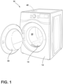
FIG. 1 is a side perspective view of a combination laundry appliance, according to the present disclosure; -
FIG. 2 is a schematic view of a drum for a laundry appliance and condensers of a heat pump assembly relative to a liquid flow path and an airflow path for the drum, according to the present disclosure; -
FIG. 3 is a schematic cross-sectional view of a combination laundry appliance having a dual condenser heat pump assembly, according to the present disclosure; -
FIG. 4 is a schematic diagram of a liquid flow path relative to a heat pump assembly and a drum for a combination laundry appliance during a wash cycle, according to the present disclosure; -
FIG. 5 is a schematic diagram of an airflow path relative to the heat pump assembly and the drum for the combination laundry appliance ofFIG. 4 during a dry cycle, according to the present disclosure; -
FIG. 6 is a side perspective view of a condenser within a reservoir for heating a wash fluid in a laundry appliance, according to the present disclosure; -
FIG. 7 is a partial side elevational view of a refrigerant line of a condenser and a liquid line in an overlapping configuration for heating a wash fluid within the liquid line, according to the present disclosure; -
FIG. 8 is a cross-sectional view of a co-extruded body having refrigerant lines and a liquid line for heating wash fluid in the liquid line, according to the present disclosure; -
FIG. 9 is a block diagram of a combination laundry appliance, according to the present disclosure; and -
FIG. 10 is a flow diagram of a method of controlling a combination laundry appliance having a dual-condenser heat pump assembly, according to the present disclosure. - The components in the figures are not necessarily to scale, emphasis instead being placed upon illustrating the principles described herein.
- The present illustrated embodiments reside primarily in combinations of method steps and apparatus components related to a combination laundry appliance with a heat pump assembly. Accordingly, the apparatus components and method steps have been represented, where appropriate, by conventional symbols in the drawings, showing only those specific details that are pertinent to understanding the embodiments of the present disclosure so as not to obscure the disclosure with details that will be readily apparent to those of ordinary skill in the art having the benefit of the description herein. Further, like numerals in the description and drawings represent like elements.
- For purposes of description herein, the terms "upper," "lower," "right," "left," "rear," "front," "vertical," "horizontal," and derivatives thereof shall relate to the disclosure as oriented in
FIG. 1 . Unless stated otherwise, the term "front" shall refer to the surface of the element closer to an intended viewer, and the term "rear" shall refer to the surface of the element further from the intended viewer. However, it is to be understood that the disclosure may assume various alternative orientations, except where expressly specified to the contrary. It is also to be understood that the specific devices and processes illustrated in the attached drawings, and described in the following specification are simply exemplary embodiments of the inventive concepts defined in the appended claims. Hence, specific dimensions and other physical characteristics relating to the embodiments disclosed herein are not to be considered as limiting, unless the claims expressly state otherwise. - The terms "including," "comprises," "comprising," or any other variation thereof, are intended to cover a non-exclusive inclusion, such that a process, method, article, or apparatus that comprises a list of elements does not include only those elements but may include other elements not expressly listed or inherent to such process, method, article, or apparatus. An element preceded by "comprises a ..." does not, without more constraints, preclude the existence of additional identical elements in the process, method, article, or apparatus that comprises the element.
- With reference to
FIGS. 1-10 ,reference numeral 10 generally designates alaundry appliance 10 that includes acabinet 12 and adrum 14 disposed within thecabinet 12. Aliquid directing system 16 is disposed within thecabinet 12 and configured to direct awash fluid 18 into thedrum 14 for awash cycle 20. Anair directing system 22 is disposed within thecabinet 12 and configured to directair 24 into thedrum 14 for adry cycle 26. Aheat pump assembly 28 is operably coupled with theliquid directing system 16 and theair directing system 22. Theheat pump assembly 28 includes anevaporator 30, afirst condenser 32 in fluid communication with theevaporator 30, asecond condenser 34 in fluid communication with theevaporator 30, and avalve 36 operably coupled to the first andsecond condensers valve 36 is configured todirect refrigerant 102 to thefirst condenser 32 during thewash cycle 20 to heat thewash fluid 18 and to thesecond condenser 34 during thedry cycle 26 to heat theair 24. Thelaundry appliance 10 also includes anelectric heater 38 disposed within thecabinet 12, which is configured to selectively heat thewash fluid 18 during a predefined mode of operation of thewash cycle 20. Acontroller 40 is communicatively coupled to theheat pump assembly 28 to control thevalve 36 to direct therefrigerant 102 based on a laundry cycle. - Referring to
FIGS. 1 and2 , thelaundry appliance 10 is illustrated as a combination washer anddryer 10, which may also be referred to as a combination washing/drying appliance 10 or acombination laundry appliance 10. Thelaundry appliance 10 includes thecabinet 12 with thedrum 14 disposed within an interior of thecabinet 12. Thecombination laundry appliance 10 includes asingle drum 14 configured to receive items for both thewash cycle 20 or phase and thedry cycle 26 or phase within thesame drum 14. Accordingly, thecombination laundry appliance 10 may perform a laundry cycle within thedrum 14 that includes both thewash phase 20 and thedry phase 26. - The
drum 14 is a rotatingdrum 14 configured to be driven about a rotational axis, which is typically a horizontal axis, as shown in the illustrated configuration. Thedrum 14 is configured to receive items, which can include but are not limited to, fabric, clothing, linens, other wearable items, and other similar items typically cleaned with thelaundry appliance 10. Thelaundry appliance 10 includes adoor 42 operably coupled to thecabinet 12 for selectively enclosing and accessing aninterior 48 of thedrum 14 for adding and removing items from thedrum 14. - The
laundry appliance 10 includes afluid directing system 50 for directing fluid within thelaundry appliance 10 during the laundry cycle (e.g., thewash phase 20 and/or the dry phase 26). Thefluid directing system 50 includes theliquid directing system 16 for directing thewash fluid 18 along aliquid flow path 52. Theliquid directing system 16 is used for directing thewash fluid 18 into thedrum 14 and recirculating thewash fluid 18 during thewash cycle 20. Thewash fluid 18 generally includes at least water, laundry chemistry, and combinations thereof. Theliquid directing system 16 includes awater inlet 60, which is in fluid communication with a water source, for directing fresh water into thelaundry appliance 10, or for directingrecirculated wash fluid 18 within thelaundry appliance 10. The water is directed from thewater inlet 60, through avalve 62, and to adispenser 64. Thedispenser 64 holds laundry chemistry, which mixes with the water as the water is directed through thedispenser 64. Thewash fluid 18, which includes one or both of water and laundry chemistry, is directed through adispenser tube 66 and into thedrum 14 to interact with the items therein during thewash cycle 20. Over the course of the laundry cycle, portions of thewash fluid 18 are typically recirculated through theappliance 10. - Referring still to
FIGS. 1-3 , thewash fluid 18 is drained from thedrum 14 via adrain line 68, which is configured to direct thewash fluid 18 to areservoir 70. Thereservoir 70 may be a sump, a container, or any practicable structure for holding and/or storing thewash fluid 18. It is also contemplated that thereservoir 70 may be included in or configured as a removable container for removing and dispensing of thewash fluid 18 after the laundry cycle. - A
pump 72 is in fluid communication with thereservoir 70 for directing thewash fluid 18 through arecirculation line 74, thevalve 62, and back to thedrum 14. In the illustrated configuration, thewash fluid 18 is directed by thevalve 62 from therecirculation line 74 through thedispenser 64. However, anadditional recirculation line 74 may be utilized for bypassing thedispenser 64 for delivering the recirculatedwash fluid 18 to thedrum 14. The fresh water from thewater inlet 60 may be added at the start of awash cycle 20 and/or may continually be added during the wash cycle. - The
combination laundry appliance 10 is also used to perform thedry cycle 26 to dry the items within thesame drum 14. Accordingly, thefluid directing system 50 includes theair directing system 22 configured to direct theair 24 along anairflow path 80 within thelaundry appliance 10. Thecabinet 12 generally defines anair inlet 82 for drawingair 24 into thelaundry appliance 10. Theair inlet 82 is in fluid communication withducting 84, which directs theair 24 to the interior 48 of thedrum 14 through adrum air inlet 86. Thedrum 14 also includes anair outlet 88 on an opposing side of thedrum 14 relative to thedrum air inlet 86. In this way, theair 24 is directed across thedrum 14 and, consequently, across the items disposed within thedrum 14 during thedry cycle 26. Theair 24 directed across thedrum 14 assists in removing moisture from thedrum 14 and items, and therefore, dries the items. Theair 24 is directed out of thedrum 14 via theair outlet 88 and through theducting 84 to be recirculated back into thedrum 14. Upon completion of thedry cycle 26, theair 24 may be exhausted from thelaundry appliance 10. - Referring still to
FIG. 2 , as well asFIG. 3 , thecombination laundry appliance 10 includes aheat pump assembly 28 having arefrigerant circuit 100 fluidly coupling various components of theheat pump assembly 28. Theheat pump assembly 28 is configured to direct a refrigerant 102 through therefrigerant circuit 100 for adjusting a temperature of each of thewash fluid 18 and theair 24 during the respective phase of the laundry cycle, as described further herein. Theheat pump assembly 28 includes thefirst condenser 32, which is configured to heat thewash fluid 18 during thewash cycle 20, and thesecond condenser 34, which is configured to heat theair 24 during thedry cycle 26. Further, theheat pump assembly 28 includes theevaporator 30 in fluid communication with each of thefirst condenser 32 and thesecond condenser 34. During thedry cycle 26, theair 24 is directed across theevaporator 30, which is configured to cool theair 24 and remove moisture from theair 24. Where it is not necessary forair 24 to be heated, the cooling function of theevaporator 30 can be used for other purposes, such as charging a heat sink, cooling the surrounding environment, and other purposes where heat may need to be extracted from a media and absorbed into theevaporator 30. - Referring still to
FIG. 2 , as well asFIGS. 4 and 5 , theheat pump assembly 28 is configured to adjust the temperature of the fluid (e.g., thewash fluid 18 or the air 24) based on the phase of the laundry cycle being performed by thecombination laundry appliance 10. Theheat pump assembly 28 is disposed within thecabinet 12 and may be arranged in any practicable configuration for affecting the temperature of thewash fluid 18 and the dryingair 24. Accordingly, the positions of the various components of theheat pump assembly 28, as illustrated inFIG. 2 , are merely exemplary and are not meant to be limiting. - The
heat pump assembly 28 includes acompressor 110, thefirst condenser 32, thesecond condenser 34, an expansion device orvalve 112, and theevaporator 30. The refrigerant 102 is directed through arefrigerant line 114 that extends therefrigerant circuit 100 and fluidly connects the various components of theheat pump assembly 28. Thecompressor 110 is configured to control or create circulation of the refrigerant 102, which acts as a pump or motor. Thecompressor 110 pressurizes the refrigerant 102 by compressing therefrigerant gas 102, decreasing the volume of the refrigerant 102, and creating a pressure difference that drives the refrigerant 102 through therefrigerant circuit 100 in a continuous cycle. - From the
compressor 110, the refrigerant 102 is directed to the three-way valve 36, which is configured to direct the refrigerant 102 to either thefirst condenser 32 or thesecond condenser 34 based on the laundry cycle. The three-way valve 36 is operable between a first state, directing the refrigerant 102 to thefirst condenser 32, and a second state, directing the refrigerant 102 to thesecond condenser 34. When the three-way valve 36 is in the first state, the refrigerant 102 bypasses thesecond condenser 34, and when the three-way valve 36 is in the second state, the refrigerant 102 bypasses thefirst condenser 32. Typically, the threeway valve 36 will be operable to deliver the refrigerant 102 thefirst condenser 32, thesecond condenser 34, but not both. - Each of the first and
second condensers refrigerant gas 102 received from thecompressor 110 into a vapor and then to a liquid. Through the process of cooling and condensing the refrigerant 102, the first andsecond condensers heat pump assembly 28 is a dual-condenser heat pump assembly 28. - Referring still to
FIGS. 4 and 5 , the refrigerant 102 is directed from thefirst condenser 32, or thesecond condenser 34, to avalve 116, such as acheck valve 116. Thecheck valve 116 is configured to prevent backflow of the refrigerant 102 into either of the first andsecond condensers check valve 116, the refrigerant 102 is directed to theexpansion valve 112. Theexpansion valve 112 is configured to control the flow of theliquid refrigerant 102 into theevaporator 30. - The refrigerant 102 is directed from the
expansion valve 112 and through theevaporator 30. Theevaporator 30 is configured to absorb heat as the refrigerant 102 flowing through theevaporator 30 is converted from a liquid to a gas, thereby absorbing heat as a result of this reaction. The refrigerant 102 then moves at a slower pace to absorb a maximum amount of heat. As the refrigerant 102 absorbs heat, the refrigerant 102 turns into a gas. By vaporizing, the refrigerant 102 absorbs more heat. Heat from the heated andhumid air 24 is absorbed by theevaporator 30, thereby cooling theair 24 and condensing the moisture within thehumid air 24 as condensate. As a result, the air is cooled and dehumidified through the operation of the refrigerant moving through theevaporator 30. The refrigerant 102 is then directed back to thecompressor 110, in a heated gaseous form, to again be compressed by thecompressor 110. Overall, theheat pump assembly 28 includes threeheat exchangers evaporator 30 and twocondensers condensers refrigerant circuit 100. Accordingly, the refrigerant 102 is directed through one of the twocondensers - Referring still to
FIG. 4 , theliquid flow path 52 is illustrated relative to the components of theheat pump assembly 28 and thedrum 14. Thewash fluid 18 that is drained from thedrum 14 is directed along theliquid flow path 52, flowing adjacent to or across thefirst condenser 32. As thewash fluid 18 is directed across thefirst condenser 32, the heat emitted from thefirst condenser 32 is transferred to thewash fluid 18. The warmed orheated wash fluid 18 then continues along theliquid flow path 52 to be delivered back into thedrum 14. During thewash cycle 20, thewash fluid 18 is recirculated, and with each recirculation, thewash fluid 18 is directed across thefirst condenser 32 to continually heat thewash fluid 18. - In various aspects, the water directed from the
water inlet 60 may be directed across thefirst condenser 32. In this way, the water (e.g., the wash fluid 18) may be warmed or heated as the water is directed through thedispenser 64 and into thedrum 14 and then continually warmed during the recirculation during thewash cycle 20. - Referring still to
FIG. 4 , as well asFIGS. 6-8 , thewash fluid 18 may flow over thefirst condenser 32 or be in close proximity with thefirst condenser 32, or other practicable configurations for maximizing the heat transfer from thefirst condenser 32 to thewash fluid 18. For example, as illustrated inFIG. 6 , thefirst condenser 32 is disposed in or operably coupled with thereservoir 70. Thewash fluid 18 is directed into thereservoir 70 from thedrain line 68 and directed out of thereservoir 70 via therecirculation line 74 and thepump 72. Thefirst condenser 32 is disposed in thereservoir 70 with arefrigerant inlet 124 and arefrigerant outlet 126 of thefirst condenser 32 extending into and out of thereservoir 70, respectively. In this configuration, thewash fluid 18 is delivered to thereservoir 70 around thefirst condenser 32. Thewash fluid 18 may directly contact and remain in contact with thefirst condenser 32 to receive the heat emitted from thefirst condenser 32 before being recirculated out of thereservoir 70 via thepump 72. - In such an aspect of the device, the
first condenser 32 can be positioned within a lower section of thereservoir 70. As portions of thewash fluid 18 heat, this fluid will rise and allowcooler fluid 18 to fall to the lower section of thereservoir 70 to be heated by thefirst condenser 32. Additionally, thefirst condenser 32 can be positioned within an upper section of thereservoir 70 to provide heat, though a longer period of time, to the immediatelyadjacent wash fluid 18 in thereservoir 70. - Further, the
first condenser 32 inFIG. 6 is illustrated as a fin-and-tube condenser 32. The fin-and-tube condenser 32 may maximize a surface area of thecondenser 32 that is configured to emit heat. In this way, the heat transfer to thewash fluid 18 may occur more efficiently, maximizing the heat transfer to thewash fluid 18 while thewash fluid 18 remains in thereservoir 70. - Referring to
FIG. 7 , aliquid line 128 and therefrigerant line 114 may be coiled together in various patterns to maximize contact and, therefore, heat transfer therebetween. Theliquid line 128 may be thedrain line 68, therecirculation line 74, thewater inlet 60, or any other tubing for directing thewash fluid 18 along theliquid flow path 52. Theliquid line 128 may form a first serpentine pattern, while therefrigerant line 114 forms a second serpentine pattern. The two serpentine patterns may be perpendicular to one another or may be parallel to one another to form a coiling and/or overlapping configuration. The coiled and overlapping configuration maximizes the surface area of therefrigerant line 114 of thefirst condenser 32 that is abutting or adjacent to theliquid line 128. The maximized surface area or contact may be advantageous for maximizing heat transfer from therefrigerant line 114 of thefirst condenser 32 to theliquid line 128, and consequently, thewash fluid 18 within theliquid line 128. - Referring to
FIG. 8 , one or morerefrigerant lines 114 may be coupled with theliquid line 128 or coextruded with theliquid line 128. In this way, multiplerefrigerant lines 114 may abut or be adjacent to theliquid line 128. In various configurations, therefrigerant lines 114 may surround theliquid line 128, allowing heat to transfer to thewash fluid 18 from multiple directions. Therefrigerant lines 114 and theliquid line 128 may be coextruded into a surroundingbody 130. In this way, therefrigerant line 114 and theliquid line 128 remain in contact or adjacent to one another to maximize the heat transfer from therefrigerant line 114 of thefirst condenser 32 to theliquid line 128. Similar to the coiling and overlapping configuration ofFIG. 7 , the coextruded configuration ofFIG. 8 may be included in one or more locations within thelaundry appliance 10, such that theliquid line 128 may be thedrain line 68, therecirculation line 74, thewater inlet 60, or any other tubing for directing thewash fluid 18 along theliquid flow path 52. - Referring again to
FIG. 4 , thelaundry appliance 10 may include theelectric heater 38 operably coupled with theliquid flow path 52. Theelectric heater 38 may direct heat to the fresh water and/or the recirculatedwash fluid 18. Theelectric heater 38 may be configured to supplement the heating of thewash fluid 18 performed by thefirst condenser 32. Supplementing the heating by thefirst condenser 32 may shorten a wash time for thewash cycle 20 by heating thewash fluid 18 more quickly. In various examples, thewash fluid 18 is configured to be heated from about 7°C to a range between about 40°C and about 50°C. In certain aspects, thefirst condenser 32 is configured to heat thewash fluid 18 to this predefined range in a first predefined mode of operation, which reduces the energy consumption of the laundry appliance 10 (e.g., conserves energy). In a second predefined mode of operation, both thefirst condenser 32 and theelectric heater 38 are configured to heat thewash fluid 18 to this predefined temperature range, which may be advantageous for reaching the predefined temperature in a shorter time and shortening the wash time. - The
wash fluid 18 is directed along thefirst condenser 32 during thewash cycle 20. Accordingly, the refrigerant 102 is directed through thefirst condenser 32 during thewash cycle 20. In this way, the three-way valve 36 is in the first state, directing the refrigerant 102 through thefirst condenser 32 and bypassing thesecond condenser 34. During thewash cycle 20, the refrigerant 102 is not moved through thesecond condenser 34 such that little or no heat is emitted by thesecond condenser 34. Accordingly, during thewash cycle 20, substantial heat is emitted by thefirst condenser 32 to heat thewash fluid 18, and minimal or no heat is emitted by thesecond condenser 34. - With reference still to
FIG. 4 , as well asFIG. 9 , thelaundry appliance 10 includes thecontroller 40, which is communicatively coupled with theheat pump assembly 28 and theelectric heater 38. Thecontroller 40 includes aprocessor 140, amemory 142, and other control circuitry. Instructions orroutines 144 are stored within thememory 142 and executable by theprocessor 140. Thecontroller 40, as disclosed herein, may include various types of control circuitry, digital or analog, and may include theprocessor 140, a microcontroller, and an application-specific integrated circuit (ASIC), or other circuitry configured to perform the various input or output, control, analysis, or other functions described herein. Thememory 142, as described herein, may be implemented in a variety of volatile and nonvolatile memory formats. Theroutines 144 include operating instructions to enable various functions described herein. - The
controller 40 is configured to activate theheat pump assembly 28, theelectric heater 38, and theliquid directing system 16. Thecontroller 40 is also configured to adjust the state of the three-way valve 36 to direct the refrigerant 102 to thefirst condenser 32 for thewash cycle 20. In various aspects, thecontroller 40 is configured to receive an input provided by the user, which may be an input through auser interface 146 connected to thelaundry appliance 10 or through wireless communication therewith. - Upon receiving the input, the
controller 40 is configured to determine which mode of operation was selected by the user for thewash cycle 20. In various aspects, thelaundry appliance 10 is configured to operate thewash cycle 20 in multiple modes of operation, such as a power-saving mode and a time-based mode. In the power-saving mode, thecontroller 40 is configured to adjust thevalve 36 to the first state to direct the refrigerant 102 through thefirst condenser 32. Thewash fluid 18 is directed across thefirst condenser 32 to be heated. In the power-saving mode, theelectric heater 38 is configured to remain in a deactivated state. Operating in the power-saving mode reduces energy consumption by thelaundry appliance 10. This mode may also be referred to as an "eco-mode" or an "economical mode." The wash time may be increased based on the single component heating with thewash fluid 18, but the power consumption by thelaundry appliance 10 may be decreased. The wash time in the power-saving mode is generally greater than the wash time in the time-based mode. - In the time-based mode, the wash time is configured to be shortened due to the shortened time it takes to heat the
wash fluid 18 to the predefined range (e.g., between about 40°C and about 50°C). In the time-based mode, thecontroller 40 is configured to adjust thevalve 36 to the first state to direct the refrigerant 102 through thefirst condenser 32. Additionally, in the time-based mode, thecontroller 40 is configured to activate theelectric heater 38 and thewash fluid 18 is configured to be directed proximate to or across from theelectric heater 38. In this way, the heating performed by thefirst condenser 32 is supplemented by theelectric heater 38. Theelectric heater 38 may be an electrical orresistive heater 34 and can be included in theheat pump assembly 28 or in a separate location in thelaundry appliance 10. With two components configured to heat thewash fluid 18, thewash fluid 18 is configured to be heated faster, decreasing the wash time. Use of theelectric heater 38 generally increases the energy used by thelaundry appliance 10. - Referring to
FIG. 5 , theairflow path 80 is illustrated relative to the components of theheat pump assembly 28 and thedrum 14. The refrigerant 102 is directed from thecompressor 110, through the three-way valve 36, and through thesecond condenser 34. The refrigerant 102 is then directed to thecheck valve 116, theexpansion valve 112, through theevaporator 30, and back to thecompressor 110. During thedry cycle 26, as illustrated inFIG. 5 , the three-way valve 36 is in the second state. The refrigerant 102 bypasses thefirst condenser 32, such that little or no heat is emitted by thefirst condenser 32. Accordingly, during thedry cycle 26, substantial heat is emitted by thesecond condenser 34 to heat theair 24 and minimal or no heat is emitted by thefirst condenser 32. - The
air directing system 22 is configured to direct theair 24 across various components of theheat pump assembly 28, through thedrum 14, and across anauxiliary heater 150. Theair 24 is directed out of thedrum 14 and across theevaporator 30. As theair 24 crosses theevaporator 30, theair 24 is dried (e.g., moisture is removed) and cooled slightly. Theair 24 is then directed across thesecond condenser 34 where thesecond condenser 34 is configured to heat theair 24 before the warmed and driedair 24 is directed back through thedrum 14. - The
air 24 is also directed across theauxiliary heater 150. In the illustrated example ofFIG. 5 , theauxiliary heater 150 is disposed along theairflow path 80 between the evaporator 30 and thesecond condenser 34. It is contemplated that theauxiliary heater 150 may be disposed along theairflow path 80 after thesecond condenser 34 without departing from the teachings herein. Theauxiliary heater 150 may be an electric orresistive heater 150 that can be utilized to supplement heating theair 24. - In various aspects, the
auxiliary heater 150 is configured to be activated for the start of thedry cycle 26 to provide an initial warming to theair 24 and then deactivated allowing thesecond condenser 34 to continue to warm theair 24. In another non-limiting example, theauxiliary heater 150 may be activated at intervals to supplement the heating performed by thesecond condenser 34. In an additional non-limiting example, theauxiliary heater 150 may remain activated during thedry cycle 26. Theair 24 is continually directed across at least theevaporator 30 and thesecond condenser 34 to be dried and warmed throughout the drying cycle. - Referring to
FIGS. 1-9 , thelaundry appliance 10 is a combination washer anddryer 10 configured to perform both thewash cycle 20 anddry cycle 26 in thesame drum 14. Thewash cycle 20 and thedry cycle 26 may be performed independently as stand-alone operations or may be performed consecutively as a comprehensive wash anddry cycle 26. Thecontroller 40 is configured to activate theheat pump assembly 28 to adjust the three-way valve 36 between the first state in thewash cycle 20 and the second state in thedry cycle 26. - The
laundry appliance 10 is configured to utilize thefirst condenser 32 for heating thewash fluid 18 during thewash cycle 20 and thesecond condenser 34 for heating theair 24 during thedry cycle 26. In this way, more heat is emitted by thefirst condenser 32 than thesecond condenser 34 duringwash cycle 20 as thesecond condenser 34 emits minimal or no heat. Further, the refrigerant 102 may move through thefirst condenser 32 to generate the heat, but may not actively move through thesecond condenser 34 during thewash cycle 20. Moreover, more heat is emitted by thesecond condenser 34 than heat emitted by thefirst condenser 32 during thedry cycle 26 as thefirst condenser 32 emits minimal or no heat. The refrigerant 102 may move through thesecond condenser 34 to generate the heat, but may not actively move through thefirst condenser 32 during thedry cycle 26. Additionally, thewash cycle 20 can be performed in two different modes of operation based on a quicker wash time (e.g., the time-based mode) and a reduction in energy consumption (e.g., the power-saving mode). - Referring to
FIG. 10 , as well asFIGS. 1-9 , amethod 160 of controlling thelaundry appliance 10 includesstep 162 of determining the mode of operation of thewash cycle 20. Thecontroller 40 is configured to receive the input from the user and based on the input, determine the mode of operation. The mode of operation is the time-based mode for thewash cycle 20 or the power-saving mode of thewash cycle 20. Instep 164, thecontroller 40 is configured to start thewash cycle 20 based on input. Step 164 may also include delivering thewash fluid 18, including the water and/or the laundry chemistry, into thedrum 14 after the items have been placed in thedrum 14. - In
step 166, thecontroller 40 is configured to activate theheat pump assembly 28. In this way, theheat pump assembly 28 is configured to begin to drive the refrigerant 102 through therefrigerant circuit 100. Instep 168, thecontroller 40 is configured to adjust the three-way valve 36 to the first state to direct the refrigerant 102 through thefirst condenser 32 to heat thewash fluid 18. During thewash cycle 20, the refrigerant 102 is continually directed through thefirst condenser 32, bypassing thesecond condenser 34. - In
step 170, thecontroller 40 is configured to determine the type ofwash cycle 20. Instep 172, for the time-based mode for the wash cycle 20 (determined in step 162), thecontroller 40 is configured to activate theelectric heater 38. In this way, theelectric heater 38 is configured to supplement the heating of thewash fluid 18 performed by thefirst condenser 32. Alternatively, instep 174, for the power-saving mode for the wash cycle 20 (determined in step 162), theelectric heater 38 is retained in the deactivated state. In this way, thewash fluid 18 is heated by thefirst condenser 32 without being supplemented by the additionalelectric heater 38. - In
step 176, thewash fluid 18 is circulated along thefirst condenser 32 for a substantial portion or the entirety of thewash cycle 20. In this way, each time thewash fluid 18 is drained from thedrum 14, thewash fluid 18 is heated before or as thewash fluid 18 is rerouted back to thedrum 14. Instep 178, thewash cycle 20 is completed, and instep 180 thedry cycle 26 is started. Thedry cycle 26 may be started based on additional input or may be based on an initial input from the user. - In
step 182, thecontroller 40 is configured to adjust the three-way valve to the second state to direct the refrigerant 102 through thesecond condenser 34 to heat theair 24. During thedry cycle 26, the refrigerant 102 is configured to be directed along therefrigerant circuit 100 through thesecond condenser 34, generally bypassing thefirst condenser 32. Accordingly, when theheat pump assembly 28 is operated with thelaundry appliance 10 in thedry cycle 26, thefirst condenser 32 emits minimal to no heat. - In
step 184, theair 24 is recirculated along theevaporator 30 and thesecond condenser 34. Theair 24 is directed through thedrum 14 gathering moisture and drying the items therein. Theair 24 is directed out of thedrum 14 and across theevaporator 30. Asair 24 circulates past theevaporator 30, moisture is removed from theair 24. Theair 24 is then directed along theairflow path 80 and across thesecond condenser 34. Thesecond condenser 34 is configured to heat theair 24, and theheated air 24 is then directed back into thedrum 14. - In
step 186, thecontroller 40 is configured to activate theauxiliary heater 150 to assist with heating theair 24. Theauxiliary heater 150 may be activated for a predefined period of time during thedry cycle 26, such as at the start of, intermittently activated, or continually activated during thedry cycle 26. Theauxiliary heater 150 may also be activated based on sensed information about the items in thedrum 14. Instep 188, thedry cycle 26 is completed, and the user may be notified that the wash and/ordry cycles method 160 may be performed in any order, simultaneously, repeated, and/or omitted without departing from the teachings provided herein. - Use of the present device may provide for a variety of advantages. For example, the
laundry appliance 10 may include three heat exchangers, including oneevaporator 30 and twocondensers condenser 32 may be utilized for thewash cycle 20, while theother condenser 34 is utilized for thedry cycle 26. In this way, more heat is emitted by thefirst condenser 32 than thesecond condenser 34 during thewash cycle 20, and more heat is emitted by thesecond condenser 34 than heat emitted by thefirst condenser 32 during thedry cycle 26. Each of the heating by thefirst condenser 32 and thesecond condenser 34 may be supplemented or initiated by therespective heater electric heater 38 or theauxiliary heater 150 may be utilized to supplement both the heating of thewash fluid 18 and theair 22. Also, thewash cycle 20 may be performed based on different predefined mode of operation, including the time-based mode and the power-saving mode. During the time-based mode, theauxiliary heater 150 can be activated to supplement the heating of thewash fluid 18 performed by thefirst condenser 32. In this way, thewash fluid 18 is heated quicker, shortening the wash time for thewash cycle 20. Further, thelaundry appliance 10 may be operated in the power-saving mode for thewash cycle 20. In such configurations, theauxiliary heater 150 remains in the deactivated state, and thewash fluid 18 is heated via thefirst condenser 32, which reduces energy consumption. Additional benefits or advantages may be realized and/or achieved. - The device disclosed herein is further summarized in the following paragraphs and is further characterized by combinations of any and all of the various aspects described therein.
- According to another aspect of the present disclosure, a combination washer and dryer includes a cabinet, a drum disposed within the cabinet, and a liquid directing system disposed within the cabinet. The liquid directing system is configured to direct liquid into the drum for a wash cycle. An air directing system is disposed within the cabinet and is configured to direct air into the drum for a dry cycle. A heat pump assembly is operably coupled to the liquid directing system and the air directing system. The heat pump assembly includes an evaporator, a first condenser in fluid communication with the evaporator, a second condenser in fluid communication with the evaporator, and a valve operably coupled to the first and second condensers. The valve is configured to direct refrigerant to the first condenser during the wash cycle to heat a wash fluid and to the second condenser during the dry cycle to heat the air. A heater is disposed within the cabinet. The heater is configured to selectively heat the wash fluid during a predefined mode of operation of the wash cycle. A controller is communicatively coupled to the heat pump assembly to control the valve to direct the refrigerant based on a laundry cycle.
- According to another aspect, a controller is configured to selectively control a heat pump assembly to operate in a time-based mode of a wash cycle and a power-saving mode of a wash cycle. A heater is activated in the time-based mode to shorten a wash time.
- According to yet another aspect, a heater is in a deactivated state during the power-saving mode of a wash cycle to conserve energy. A wash time in the power-saving mode is greater than the wash time in a time-based mode.
- According to another aspect, a valve is a three-way valve operable between a first state to direct refrigerant to a first condenser and a second state to direct the refrigerant to a second condenser.
- According to yet another aspect, more heat is emitted by a first condenser than a second condenser during a wash cycle, and more heat is emitted by the second condenser than heat emitted by the first condenser during a dry cycle.
- According to another aspect, an evaporator is configured to reduce moisture in air during a dry cycle.
- According to yet another aspect, an auxiliary heater is operably coupled to an air directing system to heat air during a dry cycle in combination with a second condenser.
- According to another aspect of the present disclosure, a combination laundry appliance includes a cabinet, a drum disposed within the cabinet, a fluid directing system for directing wash fluid into the drum during a wash cycle and directing air into the drum during a dry cycle, and a heat pump assembly operably coupled to the fluid directing system. The heat pump assembly includes a first condenser, a second condenser, and a three-way valve. The three-way valve is configured to direct refrigerant to the first condenser during the wash cycle to heat the wash fluid and to the second condenser during the dry cycle to heat the air. A controller is communicatively coupled to the heat pump assembly. The controller is configured to control the three-way valve to direct the refrigerant based on a laundry cycle.
- According to yet another aspect, a three-way valve is in a first state during a wash laundry cycle to direct refrigerant to a first condenser. The three-way valve is in a second state during a drying laundry cycle to direct the refrigerant to a second condenser.
- According to another aspect, more heat is emitted by a first condenser than a second condenser during a wash cycle, and more heat is emitted by the second condenser than heat emitted by the first condenser during a dry cycle.
- According to yet another aspect, a fluid directing system includes a liquid directing system for directing wash fluid from an inlet into a drum. The liquid directing system recirculates the wash fluid during a wash cycle.
- According to another aspect, a liquid directing system recirculates a wash fluid along a first condenser to be heated throughout a wash cycle.
- According to yet another aspect, a fluid directing system includes an air directing system for recirculating air during a dry cycle. The air is directed along an evaporator and a second condenser throughout the dry cycle.
- According to another aspect, an electric heater is operably coupled to a fluid directing system. The electric heater is selectively activated by a controller to heat a wash fluid with a first condenser to shorten a wash time.
- According to yet another aspect, a first condenser and a second condenser are arranged in parallel in a refrigerant circuit of a heat pump assembly.
- According to another aspect of the present disclosure, a method of controlling a combination laundry appliance includes starting a wash cycle in a drum of said combination laundry appliance and activating a heat pump assembly to direct refrigerant through the heat pump assembly, where the heat pump assembly having a first condenser and a second condenser. The method also includes adjusting a three-way valve to a first state to direct the refrigerant through the first condenser during the wash cycle to heat wash fluid to be directed into the drum, starting a dry cycle in the drum upon completion of the wash cycle, and adjusting the three-way valve to a second state to direct the refrigerant through the second condenser during the dry cycle to heat air to be directed into the drum.
- According to yet another aspect, a method includes determining a mode of operation of a wash cycle. The mode of operation is one of a time-based mode of operation and a power-saving mode of operation.
- According to another aspect, a method includes activating an electric heater operably coupled with a wash fluid to heat the wash fluid during a time-based mode of a wash cycle to shorten a wash time.
- According to yet another aspect, a method includes retaining the electric heater in a deactivated state in a power-saving mode of operation of a wash cycle.
- According to another aspect, a step of adjusting a three-way valve to a first state includes directing refrigerant away from a second condenser during a wash cycle, and a step adjusting the three-way valve to a second state includes directing the refrigerant away from a first condenser during a dry cycle.
- According to another aspect, a method includes recirculating a wash fluid along a first condenser during a wash cycle to continually heat the wash fluid.
- For purposes of this disclosure, the term "coupled" (in all of its forms, couple, coupling, coupled, etc.) generally means the joining of two components (electrical or mechanical) directly or indirectly to one another. Such joining may be stationary in nature or movable in nature. Such joining may be achieved with the two components (electrical or mechanical) and any additional intermediate members being integrally formed as a single unitary body with one another or with the two components. Such joining may be permanent in nature or may be removable or releasable in nature unless otherwise stated.
Claims (15)
- A combination washer and dryer (10), comprising:a cabinet (12);a drum (14) disposed within the cabinet (12);a liquid directing system (16) disposed within the cabinet (12) and configured to direct wash fluid (18) into the drum (14) for a wash cycle (20);an air directing system (22) disposed within the cabinet (12) and configured to direct air (24) into the drum (14) for a dry cycle (26);a heat pump assembly (28) operably coupled to the liquid directing system (16) and the air directing system (22), wherein the heat pump assembly (28) includes:an evaporator (30);a first condenser (32) in fluid communication with the evaporator (30);a second condenser (34) in fluid communication with the evaporator (30); anda valve (36) operably coupled to the first and second condensers (32, 34), wherein the valve (36) is configured to direct refrigerant (102) to the first condenser (32) during the wash cycle (20) to heat the wash fluid (18) and to the second condenser (34) during the dry cycle (26) to heat the air (24);a heater (38) disposed within the cabinet (12), wherein the heater (38) is configured to selectively heat the wash fluid (18) during a predefined mode of operation of the wash cycle (20); anda controller (40) communicatively coupled to the heat pump assembly (28) to control the valve (36) to direct the refrigerant (102) based on a laundry cycle (20, 26).
- The combination washer and dryer (10) of claim 1, wherein the valve (36) is a three-way valve (36), and wherein the three-way valve (36) is in a first state during the wash cycle (20) to direct the refrigerant (102) to the first condenser (32), and wherein the three-way valve (36) is in a second state during the dry cycle (26) to direct the refrigerant (102) to the second condenser (34).
- The combination washer and dryer (10) of claim 2, wherein the refrigerant (102) is directed away from the second condenser (34) during the wash cycle (20) when the three-way valve (36) is in the first state, and wherein the refrigerant (102) is directed away from the first condenser (32) during the dry cycle (26) when the three-way valve (36) is in the second state.
- The combination washer and dryer (10) of any one of claims 1-3, wherein the liquid directing system (16) recirculates the wash fluid (18) along the first condenser (32) to be heated throughout the wash cycle (20).
- The combination washer and dryer (10) of any one of claims 1-4, wherein the air directing system (22) recirculates the air (24) during the dry cycle (26), and wherein the air (24) is directed along the evaporator (30) and the second condenser (34) throughout the dry cycle (26).
- The combination washer and dryer (10) of claim 5, wherein the evaporator (30) is configured to reduce moisture in the air (24) during the dry cycle (26).
- The combination washer and dryer (10) of any one of claims 1-6, wherein the controller (40) is configured to selectively control the heat pump assembly (28) to operate in a time-based mode of the wash cycle (20) and a power-saving mode of the wash cycle (20).
- The combination washer and dryer (10) of claim 7, wherein the heater (38) is activated in the time-based mode to shorten a wash time.
- The combination washer and dryer (10) of either one of claims 7 or 8, wherein the heater (38) is in a deactivated state during the power-saving mode of the wash cycle (20) to conserve energy.
- The combination washer and dryer (10) of any one of claims 7-9, wherein the wash time in the power-saving mode is greater than the wash time in the time-based mode.
- The combination washer and dryer (10) of any one of claims 1-10, wherein more heat is emitted by the first condenser (32) than the second condenser (34) during the wash cycle (20).
- The combination washer and dryer (10) of any one of claims 1-11, wherein more heat is emitted by the second condenser (34) than heat emitted by the first condenser (32) during the dry cycle (26).
- The combination washer and dryer (10) of any one of claims 1-12, further comprising:
an auxiliary heater (38) operably coupled to the air directing system (22) to heat the air (24) during the dry cycle (26) in combination with the second condenser (34). - The combination washer and dryer (10) of any one of claims 1-13, wherein the first condenser (32) and the second condenser (34) are arranged in parallel in a refrigerant (102) circuit of the heat pump assembly (28).
- A method (160) of controlling the combination washer and dryer (10) of any one of claims 1-14, comprising:starting the wash cycle (20) (164) in the drum (14) of said combination washer and dryer (10);activating the heat pump assembly (28) (166) to direct the refrigerant (102) through the heat pump assembly (28), the heat pump assembly (28) having the first condenser (32) and the second condenser (34);adjusting the valve (36) to a first state (168) to direct the refrigerant (102) through the first condenser (32) during the wash cycle (20) to heat the wash fluid (18) to be directed into the drum (14);starting the dry cycle (26) (180) in the drum (14) upon completion of the wash cycle (20);
andadjusting the valve (36) to a second state (182) to direct the refrigerant (102) through the second condenser (34) during the dry cycle (26) to heat the air (24) to be directed into the drum (14).
Applications Claiming Priority (1)
| Application Number | Priority Date | Filing Date | Title |
|---|---|---|---|
| US18/103,795 US12590403B2 (en) | 2023-01-31 | 2023-01-31 | Combination laundry appliance with heat pump assembly |
Publications (1)
| Publication Number | Publication Date |
|---|---|
| EP4411056A1 true EP4411056A1 (en) | 2024-08-07 |
Family
ID=89772286
Family Applications (1)
| Application Number | Title | Priority Date | Filing Date |
|---|---|---|---|
| EP24154719.9A Withdrawn EP4411056A1 (en) | 2023-01-31 | 2024-01-30 | Combination laundry appliance with heat pump assembly |
Country Status (3)
| Country | Link |
|---|---|
| US (1) | US12590403B2 (en) |
| EP (1) | EP4411056A1 (en) |
| CN (1) | CN118422455A (en) |
Families Citing this family (1)
| Publication number | Priority date | Publication date | Assignee | Title |
|---|---|---|---|---|
| DE102021201241A1 (en) * | 2021-02-10 | 2022-08-11 | BSH Hausgeräte GmbH | Laundry care device with a control |
Citations (4)
| Publication number | Priority date | Publication date | Assignee | Title |
|---|---|---|---|---|
| WO2014082970A1 (en) * | 2012-11-27 | 2014-06-05 | Electrolux Home Products Corporation N.V. | Laundry washer-dryer |
| WO2016112661A1 (en) * | 2015-01-12 | 2016-07-21 | 青岛海尔洗衣机有限公司 | Laundry dryer control method and laundry dryer |
| EP3309293A1 (en) * | 2016-10-14 | 2018-04-18 | Whirlpool Corporation | Combination washing/drying laundry appliance having a heat pump system with reversible condensing and evaporating heat exchangers |
| US20220349105A1 (en) * | 2021-04-30 | 2022-11-03 | Haier Us Appliance Solutions, Inc. | Adjusted operation of a combination washer/dryer appliance |
Family Cites Families (13)
| Publication number | Priority date | Publication date | Assignee | Title |
|---|---|---|---|---|
| ES2322774T3 (en) | 2006-02-21 | 2009-06-26 | Electrolux Home Products Corporation N.V. | DOMESTIC CLOTHES DRYING MACHINE WITH ADDITIONAL CONDENSER. |
| KR101989522B1 (en) | 2012-10-22 | 2019-09-30 | 엘지전자 주식회사 | A clothes dryer |
| EP2746454A1 (en) | 2012-12-18 | 2014-06-25 | Electrolux Home Products Corporation N.V. | Washer-dryer machine |
| PL3068941T3 (en) * | 2013-11-13 | 2022-08-16 | Electrolux Appliances Aktiebolag | Heat pump washing apparatus |
| PL2878250T3 (en) * | 2013-11-29 | 2020-09-07 | Electrolux Appliances Aktiebolag | Method of operating a water-circulating household appliance |
| CN104928883A (en) | 2014-03-20 | 2015-09-23 | 海尔集团公司 | Heat-pump type washing-drying integrated machine |
| WO2015155643A1 (en) | 2014-04-07 | 2015-10-15 | Indesit Company S.P.A. | Washing and drying machine |
| DE102014118791A1 (en) | 2014-12-17 | 2016-06-23 | Miele & Cie. Kg | Apparatus and method for providing heating power to a laundry treating appliance and laundry treating appliance |
| DE102014118793A1 (en) * | 2014-12-17 | 2016-06-23 | Miele & Cie. Kg | Apparatus and method for heating a treatment liquid for a laundry treating appliance and laundry treating appliance |
| EP3124668B1 (en) | 2015-07-27 | 2021-04-14 | Electrolux Appliances Aktiebolag | Drying method for washer dryer with siphon filling and washer dryer |
| WO2017089906A1 (en) | 2015-11-24 | 2017-06-01 | BSH Hausgeräte GmbH | Household appliance with a heat pump and method for operating a household appliance |
| CN107022866B (en) * | 2017-03-01 | 2020-07-14 | 无锡小天鹅电器有限公司 | Washing and drying integrated machine and control method thereof |
| CN109695134A (en) * | 2017-10-24 | 2019-04-30 | 青岛海尔滚筒洗衣机有限公司 | A kind of heat-pump-type washing machine and control method |
-
2023
- 2023-01-31 US US18/103,795 patent/US12590403B2/en active Active
-
2024
- 2024-01-30 EP EP24154719.9A patent/EP4411056A1/en not_active Withdrawn
- 2024-01-31 CN CN202410134806.3A patent/CN118422455A/en active Pending
Patent Citations (4)
| Publication number | Priority date | Publication date | Assignee | Title |
|---|---|---|---|---|
| WO2014082970A1 (en) * | 2012-11-27 | 2014-06-05 | Electrolux Home Products Corporation N.V. | Laundry washer-dryer |
| WO2016112661A1 (en) * | 2015-01-12 | 2016-07-21 | 青岛海尔洗衣机有限公司 | Laundry dryer control method and laundry dryer |
| EP3309293A1 (en) * | 2016-10-14 | 2018-04-18 | Whirlpool Corporation | Combination washing/drying laundry appliance having a heat pump system with reversible condensing and evaporating heat exchangers |
| US20220349105A1 (en) * | 2021-04-30 | 2022-11-03 | Haier Us Appliance Solutions, Inc. | Adjusted operation of a combination washer/dryer appliance |
Also Published As
| Publication number | Publication date |
|---|---|
| US20240254683A1 (en) | 2024-08-01 |
| US12590403B2 (en) | 2026-03-31 |
| CN118422455A (en) | 2024-08-02 |
Similar Documents
| Publication | Publication Date | Title |
|---|---|---|
| EP1209277B1 (en) | Heat-pump clothes drying machine | |
| CN104040066B (en) | appliance for drying clothes | |
| JP4889545B2 (en) | Drying apparatus and washing and drying machine equipped with this apparatus | |
| CN104053832B (en) | Appliance for drying laundry | |
| CN105734936B (en) | Device for clothing processing | |
| US9372031B2 (en) | Appliance for drying laundry | |
| US9146056B2 (en) | Laundry treating apparatus having expansion valve which is variable according to the driving mode | |
| US20100132216A1 (en) | Dryer with a heat pump and an electrical heating element and also a method for its operation | |
| WO2013102604A1 (en) | Appliance for drying laundry | |
| EP2390397A1 (en) | A method for operating a washing cycle and a subsequent drying cycle in a laundry washer-dryer | |
| US20200163525A1 (en) | Control method for dish washer | |
| JP2005024113A (en) | Dryer | |
| CN108289589B (en) | Household appliance with heat pump and method for operating a household appliance | |
| EP2781644A1 (en) | Laundry treatment apparatus with heat pump | |
| WO2005080896A1 (en) | Heat pump apparatus and operating method thereof | |
| US12590403B2 (en) | Combination laundry appliance with heat pump assembly | |
| JP2012115297A (en) | Clothes dryer | |
| JP4384203B2 (en) | Clothes dryer | |
| EP2586905B1 (en) | A laundry dryer with a heat pump system | |
| EP2312049B1 (en) | A tumble dryer with a heat pump system | |
| EP2735637A1 (en) | Laundry washer-dryer | |
| JP2007143735A (en) | Washing and drying machine | |
| EP2366828A1 (en) | Laundry dryer machine with improved condenser cooling system | |
| JP4416135B2 (en) | Dishwasher and drying method thereof | |
| BR102024002027A2 (en) | LAUNDRY WASHING APPLIANCE COMBINED WITH HEAT PUMP SET |
Legal Events
| Date | Code | Title | Description |
|---|---|---|---|
| PUAI | Public reference made under article 153(3) epc to a published international application that has entered the european phase |
Free format text: ORIGINAL CODE: 0009012 |
|
| STAA | Information on the status of an ep patent application or granted ep patent |
Free format text: STATUS: THE APPLICATION HAS BEEN PUBLISHED |
|
| AK | Designated contracting states |
Kind code of ref document: A1 Designated state(s): AL AT BE BG CH CY CZ DE DK EE ES FI FR GB GR HR HU IE IS IT LI LT LU LV MC ME MK MT NL NO PL PT RO RS SE SI SK SM TR |
|
| STAA | Information on the status of an ep patent application or granted ep patent |
Free format text: STATUS: THE APPLICATION IS DEEMED TO BE WITHDRAWN |
|
| 18D | Application deemed to be withdrawn |
Effective date: 20250208 |