EP4411047A1 - Washing machine control method and washing machine - Google Patents
Washing machine control method and washing machine Download PDFInfo
- Publication number
- EP4411047A1 EP4411047A1 EP22889063.8A EP22889063A EP4411047A1 EP 4411047 A1 EP4411047 A1 EP 4411047A1 EP 22889063 A EP22889063 A EP 22889063A EP 4411047 A1 EP4411047 A1 EP 4411047A1
- Authority
- EP
- European Patent Office
- Prior art keywords
- sewage
- water
- pump assembly
- washing machine
- outlet
- Prior art date
- Legal status (The legal status is an assumption and is not a legal conclusion. Google has not performed a legal analysis and makes no representation as to the accuracy of the status listed.)
- Pending
Links
- 238000005406 washing Methods 0.000 title claims abstract description 127
- 238000000034 method Methods 0.000 title claims abstract description 40
- 238000001914 filtration Methods 0.000 claims abstract description 291
- XLYOFNOQVPJJNP-UHFFFAOYSA-N water Substances O XLYOFNOQVPJJNP-UHFFFAOYSA-N 0.000 claims abstract description 278
- 239000010865 sewage Substances 0.000 claims abstract description 178
- 230000008569 process Effects 0.000 claims abstract description 23
- 230000007246 mechanism Effects 0.000 claims description 102
- 238000004140 cleaning Methods 0.000 claims description 20
- 230000000903 blocking effect Effects 0.000 claims description 12
- 239000002245 particle Substances 0.000 claims description 11
- 239000008400 supply water Substances 0.000 claims description 2
- 239000012535 impurity Substances 0.000 abstract description 61
- 238000009825 accumulation Methods 0.000 abstract description 7
- 238000007789 sealing Methods 0.000 description 46
- 238000011084 recovery Methods 0.000 description 26
- 238000009434 installation Methods 0.000 description 8
- 230000009286 beneficial effect Effects 0.000 description 6
- 238000010586 diagram Methods 0.000 description 6
- 239000003599 detergent Substances 0.000 description 4
- 238000007599 discharging Methods 0.000 description 4
- 239000003657 drainage water Substances 0.000 description 4
- 230000003014 reinforcing effect Effects 0.000 description 4
- 238000013019 agitation Methods 0.000 description 3
- 230000008859 change Effects 0.000 description 3
- 230000000694 effects Effects 0.000 description 3
- 230000002093 peripheral effect Effects 0.000 description 3
- 230000009471 action Effects 0.000 description 2
- 238000004891 communication Methods 0.000 description 2
- 230000018044 dehydration Effects 0.000 description 2
- 238000006297 dehydration reaction Methods 0.000 description 2
- 230000008021 deposition Effects 0.000 description 2
- 238000002474 experimental method Methods 0.000 description 2
- 230000036541 health Effects 0.000 description 2
- 238000003780 insertion Methods 0.000 description 2
- 230000037431 insertion Effects 0.000 description 2
- 239000000203 mixture Substances 0.000 description 2
- 230000004048 modification Effects 0.000 description 2
- 238000012986 modification Methods 0.000 description 2
- 239000008237 rinsing water Substances 0.000 description 2
- 238000003756 stirring Methods 0.000 description 2
- 238000005728 strengthening Methods 0.000 description 2
- 241000894006 Bacteria Species 0.000 description 1
- 230000004913 activation Effects 0.000 description 1
- 238000010276 construction Methods 0.000 description 1
- 125000004122 cyclic group Chemical group 0.000 description 1
- 230000003247 decreasing effect Effects 0.000 description 1
- 230000007812 deficiency Effects 0.000 description 1
- 238000013461 design Methods 0.000 description 1
- 230000009977 dual effect Effects 0.000 description 1
- 238000005516 engineering process Methods 0.000 description 1
- 238000004519 manufacturing process Methods 0.000 description 1
Images



Classifications
-
- D—TEXTILES; PAPER
- D06—TREATMENT OF TEXTILES OR THE LIKE; LAUNDERING; FLEXIBLE MATERIALS NOT OTHERWISE PROVIDED FOR
- D06F—LAUNDERING, DRYING, IRONING, PRESSING OR FOLDING TEXTILE ARTICLES
- D06F33/00—Control of operations performed in washing machines or washer-dryers
- D06F33/30—Control of washing machines characterised by the purpose or target of the control
- D06F33/32—Control of operational steps, e.g. optimisation or improvement of operational steps depending on the condition of the laundry
- D06F33/42—Control of operational steps, e.g. optimisation or improvement of operational steps depending on the condition of the laundry of draining
-
- D—TEXTILES; PAPER
- D06—TREATMENT OF TEXTILES OR THE LIKE; LAUNDERING; FLEXIBLE MATERIALS NOT OTHERWISE PROVIDED FOR
- D06F—LAUNDERING, DRYING, IRONING, PRESSING OR FOLDING TEXTILE ARTICLES
- D06F39/00—Details of washing machines not specific to a single type of machines covered by groups D06F9/00 - D06F27/00
- D06F39/08—Liquid supply or discharge arrangements
- D06F39/083—Liquid discharge or recirculation arrangements
- D06F39/085—Arrangements or adaptations of pumps
-
- B—PERFORMING OPERATIONS; TRANSPORTING
- B01—PHYSICAL OR CHEMICAL PROCESSES OR APPARATUS IN GENERAL
- B01D—SEPARATION
- B01D33/00—Filters with filtering elements which move during the filtering operation
- B01D33/06—Filters with filtering elements which move during the filtering operation with rotary cylindrical filtering surfaces, e.g. hollow drums
-
- B—PERFORMING OPERATIONS; TRANSPORTING
- B01—PHYSICAL OR CHEMICAL PROCESSES OR APPARATUS IN GENERAL
- B01D—SEPARATION
- B01D35/00—Filtering devices having features not specifically covered by groups B01D24/00 - B01D33/00, or for applications not specifically covered by groups B01D24/00 - B01D33/00; Auxiliary devices for filtration; Filter housing constructions
- B01D35/02—Filters adapted for location in special places, e.g. pipe-lines, pumps, stop-cocks
-
- D—TEXTILES; PAPER
- D06—TREATMENT OF TEXTILES OR THE LIKE; LAUNDERING; FLEXIBLE MATERIALS NOT OTHERWISE PROVIDED FOR
- D06F—LAUNDERING, DRYING, IRONING, PRESSING OR FOLDING TEXTILE ARTICLES
- D06F33/00—Control of operations performed in washing machines or washer-dryers
- D06F33/30—Control of washing machines characterised by the purpose or target of the control
- D06F33/43—Control of cleaning or disinfection of washing machine parts, e.g. of tubs
-
- D—TEXTILES; PAPER
- D06—TREATMENT OF TEXTILES OR THE LIKE; LAUNDERING; FLEXIBLE MATERIALS NOT OTHERWISE PROVIDED FOR
- D06F—LAUNDERING, DRYING, IRONING, PRESSING OR FOLDING TEXTILE ARTICLES
- D06F39/00—Details of washing machines not specific to a single type of machines covered by groups D06F9/00 - D06F27/00
- D06F39/08—Liquid supply or discharge arrangements
- D06F39/083—Liquid discharge or recirculation arrangements
-
- D—TEXTILES; PAPER
- D06—TREATMENT OF TEXTILES OR THE LIKE; LAUNDERING; FLEXIBLE MATERIALS NOT OTHERWISE PROVIDED FOR
- D06F—LAUNDERING, DRYING, IRONING, PRESSING OR FOLDING TEXTILE ARTICLES
- D06F39/00—Details of washing machines not specific to a single type of machines covered by groups D06F9/00 - D06F27/00
- D06F39/08—Liquid supply or discharge arrangements
- D06F39/087—Water level measuring or regulating devices
-
- D—TEXTILES; PAPER
- D06—TREATMENT OF TEXTILES OR THE LIKE; LAUNDERING; FLEXIBLE MATERIALS NOT OTHERWISE PROVIDED FOR
- D06F—LAUNDERING, DRYING, IRONING, PRESSING OR FOLDING TEXTILE ARTICLES
- D06F39/00—Details of washing machines not specific to a single type of machines covered by groups D06F9/00 - D06F27/00
- D06F39/10—Filtering arrangements
-
- D—TEXTILES; PAPER
- D06—TREATMENT OF TEXTILES OR THE LIKE; LAUNDERING; FLEXIBLE MATERIALS NOT OTHERWISE PROVIDED FOR
- D06F—LAUNDERING, DRYING, IRONING, PRESSING OR FOLDING TEXTILE ARTICLES
- D06F2103/00—Parameters monitored or detected for the control of domestic laundry washing machines, washer-dryers or laundry dryers
- D06F2103/42—Parameters monitored or detected for the control of domestic laundry washing machines, washer-dryers or laundry dryers related to filters or pumps
-
- D—TEXTILES; PAPER
- D06—TREATMENT OF TEXTILES OR THE LIKE; LAUNDERING; FLEXIBLE MATERIALS NOT OTHERWISE PROVIDED FOR
- D06F—LAUNDERING, DRYING, IRONING, PRESSING OR FOLDING TEXTILE ARTICLES
- D06F2105/00—Systems or parameters controlled or affected by the control systems of washing machines, washer-dryers or laundry dryers
- D06F2105/08—Draining of washing liquids
-
- D—TEXTILES; PAPER
- D06—TREATMENT OF TEXTILES OR THE LIKE; LAUNDERING; FLEXIBLE MATERIALS NOT OTHERWISE PROVIDED FOR
- D06F—LAUNDERING, DRYING, IRONING, PRESSING OR FOLDING TEXTILE ARTICLES
- D06F2105/00—Systems or parameters controlled or affected by the control systems of washing machines, washer-dryers or laundry dryers
- D06F2105/34—Filtering, e.g. control of lint removal devices
-
- Y—GENERAL TAGGING OF NEW TECHNOLOGICAL DEVELOPMENTS; GENERAL TAGGING OF CROSS-SECTIONAL TECHNOLOGIES SPANNING OVER SEVERAL SECTIONS OF THE IPC; TECHNICAL SUBJECTS COVERED BY FORMER USPC CROSS-REFERENCE ART COLLECTIONS [XRACs] AND DIGESTS
- Y02—TECHNOLOGIES OR APPLICATIONS FOR MITIGATION OR ADAPTATION AGAINST CLIMATE CHANGE
- Y02B—CLIMATE CHANGE MITIGATION TECHNOLOGIES RELATED TO BUILDINGS, e.g. HOUSING, HOUSE APPLIANCES OR RELATED END-USER APPLICATIONS
- Y02B40/00—Technologies aiming at improving the efficiency of home appliances, e.g. induction cooking or efficient technologies for refrigerators, freezers or dish washers
Definitions
- the disclosure belongs to the technical field of washing machines, and specifically relates to a control method for a washing machine and a washing machine.
- the filter of the existing washing machine is generally installed inside the inner barrel or the drainage pump, and is used to filter lint and debris in the washing water.
- the filter will be filled with lint and debris, which will affect the filtration effect of the filter, cause the drain valve/drain pump to become blocked, and it is easy to breed bacteria. It needs to be cleaned in time, otherwise it will cause pollution of the washing water, and cause secondary pollution to the clothes, and affect the health of users.
- most washing machines require users to remove the filter and clean it manually, which is inconvenient to operate.
- the prior art has proposed a filtering device with a self-cleaning function, which can automatically clean filtered impurities such as lint shavings attached inside after completing the filtration process, and discharge the cleaned filtered impurities through the water flow.
- filtered impurities such as lint shavings attached inside after completing the filtration process
- most washing machines clean the filtering device and discharge the sewage only after the washing or rinsing phase is completed, or even after the washing machine runs a complete washing cycle.
- the filtered impurities may cover the filtering device.
- the filter screen affects the filtration efficiency of filtering impurities. In severe cases, it may also cause filtered impurities to become clogged, causing the cyclic filtration to be unable to continue, affecting the user experience.
- the technical problem to be solved by the present disclosure is to overcome the deficiencies of the prior art and provide a control method for the washing machine and a washing machine.
- the washing machine alternately performs a circulation filtration operation and a sewage discharge operation during the washing/rinsing process, and can perform the circulation filtration operation in the process.
- the filtered impurities remaining inside the filtering device are discharged in time to avoid the accumulation of filtered impurities inside the filtering device and affecting the filtration efficiency.
- a control method for a washing machine comprising:
- the pump assembly is controlled to be turned on intermittently; preferably, the circulating filtration operation includes the following steps:
- the pump assembly continues to operate for a first preset time period T 1 after being turned on for a first time, and the pump assembly continues to operate for a second preset time length T 2 after each subsequent turn on; the first preset time length T 1 is greater than the second preset time length T 2 .
- the filtering device includes:
- step S3 the filtering mechanism continues to rotate while the pump assembly is turned off, and each time the drive mechanism is turned on, the filtering mechanism continues to rotate for a same length of time; preferably, in step S2, the pump assembly continues to operate at least the second preset time length T 2 after being turned on, in step S3, the filtering mechanism continues to operate a third preset time length T 3 , and the third preset time length T 3 is less than the second preset time length T 2 .
- the washing machine further includes a discharge pipeline for draining water to outside, and the control valve assembly connects the sewage outlet and the sewage pipeline while connecting the pump assembly and the discharge pipeline; after the washing or the rinsing process is completed, the control valve assembly connects the pump assembly and the discharge pipeline, turns on the pump assembly, and the water in the water container is discharged from the washing machine through the discharge pipeline.
- control valve assembly connects the pump assembly and the water inlet and disconnects the sewage outlet and the sewage pipeline;
- Another object of the present disclosure is to provide a washing machine that adopts the above-mentioned control method for the washing machine.
- control valve assembly comprising:
- the filtering device comprising:
- the present disclosure has the following beneficial effects compared with the prior art.
- the washing machine alternately performs the circulating filtration operation and the sewage discharge operation during the washing/rinsing process, so that the filtered impurities remaining inside the filtering device during the circulating filtration operation can be discharged in time, and the accumulation of filtered impurities inside the filtering device can be avoided.
- the method of continuously performing circulating filtration operation until the end of washing/rinsing it prevents excessive accumulation of filtered impurities from causing clogging of the filtration device.
- the pump assembly is intermittently turned on during the circulating filtration operation of the washing machine.
- the closing of the pump assembly provides an opportunity for the filtered impurities attached to the interior of the filtering device to fall off, preventing the filtered impurities from being too firmly attached to the interior of the filtering device.
- the driving mechanism drives the filtering mechanism to rotate, which can stir the water in the filtering cavity, thereby generating agitated water flow.
- the filtered impurities attached to the outer wall of the filtering mechanism can be peeled off under the dual effects of the centrifugal force generated by the rotation and the agitated water flow. It is helpful to improve the cleaning efficiency of filtering impurities.
- control valve assembly as an integral structure, can simultaneously control the on-off of multiple independent waterways through changes in the position of the switching mechanism, and then control the washing machine to perform circulating filtration operation, sewage discharge operation and drainage operations respectively through the on-off conditions of the waterways, which simplifies the control structure and control logic of the water path inside the washing machine, which is beneficial to reducing production costs.
- cleaning particles are arranged in the filtering cavity.
- the cleaning particles are driven by the water flow and continuously rub against the inner wall of the filtering cavity and the outer wall of the filtering mechanism, which can further prevent the deposition of filtered impurities, thereby avoiding clogging of the filtering device and affecting the filtration efficiency.
- the filtering mechanism is controlled to rotate in the filtering cavity, the cleaning particles move with the water flow, which is conducive to further strengthening the agitation of the water flow, thereby making it easier for attached filtered impurities to fall off, and improving the self-cleaning efficiency of the filtering device.
- connection should be understood in a broad sense.
- connection can be a fixed connection or a detachable connection.
- Connection, or integral connection can be a mechanical connection or an electrical connection; it can be a direct connection or an indirect connection through an intermediate medium.
- connection or integral connection
- connection can be a mechanical connection or an electrical connection
- connection can be a direct connection or an indirect connection through an intermediate medium.
- specific meanings of the above terms in the present disclosure can be understood on a case-by-case basis.
- the washing machine in this embodiment includes:
- control valve assembly 700 includes:
- the water inlet 701 of the first valve chamber 711 and the sewage outlet 705 of the second valve chamber 712 are open by default.
- the switching mechanism 720 is in the first position, the water inlet 701 and the circulating water outlet 702 are both open, and the pump assembly 400 is connected to the water inlet 6101 of the filtering device 600; at the same time, the sewage inlet 704 is blocked, and the filtering device 600 is disconnected from the sewage outlet 6103 and the sewage pipeline 240.
- the switching mechanism 720 When the switching mechanism 720 is in the second position, the circulating water outlet 702 is in a blocked state, and the pump assembly 400 is disconnected from the water inlet 6101 of the filtering device 600; at the same time, the sewage inlet 704 and the sewage outlet 705 are both open, and the sewage outlet 6103 of the filtering device 600 is connected to the sewage pipeline 240.
- the control valve assembly 700 of this embodiment has two working states, corresponding to the switching mechanism 720 being in different positions. Specifically, the first working state of the control valve assembly 700 is that the switching mechanism 720 is in the first position, connecting the pump assembly 400 and the water inlet 6101 and disconnecting the sewage outlet 6103 and the sewage pipeline 240; the second working state of the control valve assembly 700 is that the switching mechanism 720 is in the second position, disconnecting the pump assembly 400 and the water inlet 6101 and connecting the sewage outlet 6103 and the sewage pipeline 240.
- control valve assembly 700 can simultaneously control the connection between the pump assembly 400 and the water inlet 6101 of the filtering device 600, and the connection between the sewage outlet 6103 of the filtering device 600 and the sewage pipeline 240.
- the filtering device 600 can be switched between the two working processes of filtration and sewage discharge.
- the control valve assembly 700 can simultaneously control the opening and closing of two relatively independent water channels, which is beneficial to simplifying the layout of the internal water channel structure of the washing machine and making the control logic of the water channel opening and closing simpler.
- the washing machine alternately performs the circulation filtering operation and the sewage discharge operation during the washing/rinsing process.
- the circulation filtering operation includes: the pump assembly 400 is in an open state, the control valve assembly 700 is in the first working state, that is, the control valve assembly 700 connects the pump assembly 400 and the water inlet 6101 and disconnects the sewage outlet 6103 and the sewage pipeline 240, the water in the water container 100 is circulated and filtered.
- the sewage discharge operation includes: the pump assembly 400 is in a closed state, the control valve assembly 700 is in the second working state, that is, the control valve assembly 700 disconnects the pump assembly 400 and the water inlet 6101 and connects the sewage outlet 6103 and the sewage pipeline 240, and the sewage in the filtering device 600 is discharged into the sewage pipeline 240.
- the filtered impurities such as lint residues remaining inside the filtering device 600 during the circulation filtering process can be discharged in a timely manner, thereby preventing the filtered impurities from being internal accumulation in the filtering device 600, affecting the filtration efficiency.
- the solution of this embodiment compared with the method of continuously performing the circulation filtering operation until the end of washing/rinsing, effectively prevents excessive accumulation of filtered impurities, causing the filtering device 600 to become clogged.
- the pump assembly 400 may be a water pump that generates suction force to draw out the water in the water container 100 for circulation filtration.
- the pump assembly 400 while the washing machine is performing a circulation filtering operation, the pump assembly 400 is controlled to be turned on intermittently. Through the intermittent opening of the pump assembly 400, during the period when the pump assembly 400 is closed, the water in the water container 100 pauses passing through the filtering device 600, and the filtered impurities attached to the inside of the filtering device 600 can fall off and merge into the water during this period, and then perform the sewage discharge operation. It is discharged with the water flow. This avoids the situation where the water flow is filtered through the filtering device 600 for too long, causing the filtered impurities to adhere too firmly inside the filtering device 600 and cannot be fully discharged during the sewage discharge operation.
- the pump assembly 400 by controlling the pump assembly 400 to be turned on intermittently during the circulation filtering operation, the pump assembly 400 can be prevented from continuing to work for a long time, the service life of the pump assembly 400 can be extended, and the control valve assembly 700 can be avoided from frequently switching. In the working state, the control valve assembly 700 is protected.
- the circulation filtering operation includes the following steps:
- the pump assembly 400 continues to run for the first preset time period T 1 after being turned on for the first time, and then continues to run for the second preset time period T 2 after being turned on each time.
- the first preset time length T 1 is greater than the second preset time length T 2 .
- a filter screen is provided inside the filtering device 600, and the filtering process is implemented through the mesh on the filter screen.
- the specific values of the first preset time length T 1 and the second preset time length T 2 can be obtained in advance through a large number of experiments and directly written into the control program of the washing machine.
- the first preset time length T 1 is specifically that the length of time it takes for most of the mesh holes on the filter to be covered by filtered impurities during continuous filtration of the filtering device 600.
- the value of the first preset time period T 1 can be larger.
- the value of the second preset time period T 2 is less than the first preset time period T 1 to avoid clogging of the filter screen and affecting the filtration process.
- the filtering device 600 includes:
- Step S3 also includes: while the pump assembly 400 is closed, the driving mechanism 660 is turned on to drive the filtering mechanism 620 to rotate in the filtering cavity 610.
- the filtering mechanism 620 divides the interior of the filtering cavity 610 into an outer cavity and an inner cavity, wherein the water inlet 6101 is connected to the outer cavity, and the filtered water outlet 6102 is connected to the inner cavity.
- the water in the water container 100 enters the outer cavity through the water inlet 6101 under the action of the pump assembly 400, and enters the inner cavity through the filtering mechanism 620 to be filtered.
- the lint carried in the water adheres to the outer wall of the filtering mechanism 620.
- the driving mechanism 660 is turned on when the pump assembly 400 is closed.
- the driving mechanism 660 drives the filtering mechanism 620 to rotate, which can stir the water flow in the filtering cavity 610, so that the filtered impurities attached to the outer wall of the filtering mechanism 620 are peeled off under the action of the combination of centrifugal force and agitation of the water flow, and blends into the water in the filtering cavity 610, which helps the filtered impurities attached to the outer wall of the filtering mechanism 620 to fully fall off.
- cleaning particles 680 are further provided in the filtering cavity 610.
- the cleaning particles 680 are used to clean the inner wall of the filtering cavity 610 and the outer wall of the filtering mechanism 620 by friction and collision with the water flow.
- the water flow continues to pass through the filtering device 600, and the cleaning particles 680 are driven by the water flow to continuously rub against the inner wall of the filtering cavity 610 and the outer wall of the filtering mechanism 620, which can slow down the deposition of filtered impurities, thereby appropriately extending duration of continuous activation of the pump assembly 400.
- the driving mechanism 660 drives the filtering mechanism 620 to rotate, the cleaning particles 680 move with the water flow, which is conducive to further strengthening the agitation of the water flow, thereby making it easier for the attached filtered impurities to fall off.
- step S3 of this embodiment the filtering mechanism 620 continues to rotate while the pump assembly 400 is closed, and each time the driving mechanism 660 is turned on, the filtering mechanism 620 continues to rotate for the same length of time.
- the continuous rotation time of the filtering mechanism 620 in step S3 is the third preset time length T 3 , and the third preset time length T 3 is less than the second preset time length T 2 .
- the third preset time period T 3 can be obtained in advance through a large number of experiments and directly written into the control program of the washing machine to ensure that filtered impurities such as lint and other lint attached to the filtering mechanism 620 can be fully shed.
- the washing machine further includes a discharge pipeline 250 for draining water to the outside.
- the control valve assembly 700 not only connects the sewage outlet 6103 and the sewage pipeline 240, but also connects the pump assembly 400 with the discharge pipeline 250.
- the first valve chamber 711 of the control valve assembly 700 is provided with a drainage outlet 703 that communicates with the discharge pipeline 250.
- the switching mechanism 720 blocks the drainage outlet 703.
- the switching mechanism 720 is in the second position and the drainage outlet 703 is opened.
- control valve assembly 700 connects the pump assembly 400 and the discharge pipeline 250, opens the pump assembly 400, and the water in the water container 100 is discharged from the washing machine through the discharge pipeline 250.
- the circulating filter pipeline of the washing machine in this embodiment specifically includes:
- the pump assembly 400 is used for both circulating filtration of water in the water container 100 and for draining water from the washing machine. Moreover, the circulating filtration and drainage share part of the pipeline structure, which simplifies the layout of the waterway structure inside the washing machine and is beneficial to save space inside the washing machine.
- the control valve assembly 700 switches to the second working state, so that between the water inlet 701 and the drainage outlet 703 of the first valve chamber 711, and between the sewage inlet 704 and the sewage outlet 705 of the second valve chamber 712 are simultaneously communicated.
- the water container 100 drains to the outside of the washing machine, at the same time, the sewage outlet 6103 of the filtering device 600 is communicated to the sewage pipeline 240, so that the sewage in the filtering device 600 can be continuously discharged while draining, ensuring the discharge rate of sewage.
- the drainage of the water container 100 and the drainage of the filtering device 600 are performed at the same time, which improves the working efficiency of the washing machine and improves the user experience.
- the return water pipeline 230 is specifically connected to the window gasket 110 at the opening of the water container 100.
- the sewage outlet 6103 of the filtering device 600 is connected to the connecting pipeline 280, the connecting pipeline 280 is connected to the sewage inlet 704 of the control valve assembly 700, and the water inlet end of the sewage pipeline 240 is connected to the sewage outlet 705 of the control valve assembly 700, forming a discharge channel of sewage in the filtering device 600.
- a return water control valve 231 is provided on the return water pipeline 230 for controlling the opening and closing of the return water pipeline 230.
- the return water control valve 231 is closed to cut off the return water pipeline 230 to ensure that the water in the filtering cavity 610 will not flow out from the filtered water outlet 6102, which is beneficial to discharging the filtered impurities residual in the filtering device 600 with the water flow.
- the control valve assembly 700 in this embodiment is shown in FIGS. 3 and 4 , where the switching mechanism 720 includes:
- the drainage outlet 703 and the sewage inlet 704 are provided on the same side surface of the valve body 710.
- the switching mechanism 720 When the switching mechanism 720 is in the first position, the drainage sealing component 733 and the sewage sealing component block the drainage outlet 703 and the sewage inlet 704 respectively; when the switching mechanism 720 is in the second position, the flap 740 moves away from the drainage outlet 703 and the sewage inlet 704 relative to the previous state until the circulation sealing component 732 blocks the circulation water outlet 702.
- the flap 740 is connected to a driving motor 750 for driving the flap 740 to rotate in the valve body 710.
- the driving motor 750 is arranged outside the valve body 710, which avoids the risk of contact with water and is safer.
- the control valve assembly 700 drives the flap 740 to move through the driving motor 750, and can simultaneously control the opening/blocking switching of the circulating water outlet 702, the drainage outlet 703 and the sewage inlet 704, and has a simple structure. Compared with the existing solution in which a driven control valve is provided for each independent waterway, the cost is effectively saved.
- first valve chamber 711 and the second valve chamber 712 of the control valve assembly 700 extend in a left and right direction and are arranged parallel to each other.
- the drainage outlet 703 is disposed on the right end cavity wall of the first valve chamber 711 in the length direction, and the sewage inlet 704 is disposed on the right end cavity wall of the second valve chamber 712.
- the water inlet 701 is provided on the left end wall of the first valve chamber 711, parallel to and opposite to the direction of the drainage outlet 703.
- the sewage outlet 705 is disposed on the left end wall of the second valve chamber 712, parallel to and opposite to the direction of the sewage inlet 704.
- the direction of the circulating water outlet 702 and the direction of the drainage outlet 703 are perpendicular to each other.
- the control valve assembly 700 switches from the first working state to the second working state.
- the flap 740 rotates 90° around its axis to move from the first position to the second position.
- the first valve chamber 711 is disposed above the second valve chamber 712, and the circulating water outlet 702 is disposed on the front wall of the first valve chamber 711.
- the flap 740 When the switching mechanism 720 is in the first position, the flap 740 is nearly parallel to the right end walls of the first valve chamber 711 and the second valve chamber 712, so that the drainage sealing component 733 blocks the drainage outlet 703, and the drainage sealing component blocks the sewage inlet. 704.
- the driving motor 750 drives the flap 740 to rotate forward 90° , causing the circulation sealing component 732 to block the circulation water outlet 702.
- the drainage sealing component 733 is separated from the drainage outlet 703, and the drainage outlet 703 is opened; the drainage sealing component is separated from the sewage inlet 704, and the sewage inlet 704 is opened.
- the control valve assembly 700 before washing/rinsing water enters, the control valve assembly 700 is switched to the first working state, that is, the pump assembly 400 and the water inlet 6101 are connected and the sewage outlet 6103 and the sewage pipeline 240 are disconnected; starting to feed water into the water container 100, after the water level in the water container 100 is greater than the preset water level, the pump assembly 400 is turned on to perform a circulating filtration operation, and after the circulating filtration operation is completed, a sewage discharge operation is performed;
- the circulating filtration operation and the sewage discharge operation are executed alternately until the washing/rinsing process is completed.
- the preset number of times described in step S4 is set to 3 times. That is, in one cycle of filtering operation, the washing machine turns on and off the pump assembly 400 three times, and when the pump assembly 400 is turned off for the third time, and after the driving mechanism 660 is turned on to drive the filtering mechanism 620 to continue to rotate in the filtering cavity 610 for the third preset time T 3 , the control valve assembly 700 switches to the second working state to perform the sewage operation.
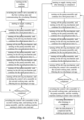
- FIG. 6 shows a flow chart of the washing machine in this embodiment running a complete washing program, which includes the following steps:
- the washing machine alternately performs circulating filtration operation and sewage discharge operation during the washing and rinsing processes, which can timely discharge the filtered impurities remaining inside the filtering device 600 through the sewage outlet 6103 to avoid accumulation of filtered impurities affecting the filtration efficiency.
- the pump assembly 400 is controlled to be turned on intermittently, and during the period when the pump assembly 400 is turned off, the filtering mechanism 620 is driven to rotate by driving the driving mechanism 660, so that filtered impurities such as lint and other lint attached to the filtering mechanism 620 are fully shed, and then the sewage is fully discharged during execution of the operation.
- the filtering device 600 can perform self-cleaning at any time during the running of the washing program, thereby avoiding the clogging of the filtering device 600 and ensuring the water filtration efficiency of the washing machine.
- a driving motor 750 can be used to control the water pumped out by the pump assembly 400 to be transported to the filtering device 600 or to the outflow pipeline 250, and at the same time control whether the sewage outlet 6103 of the filtering device 600 discharges sewage to the outside.
- the washing machine's circulating filtering operation, sewage discharge operation, and drainage operation are all controlled by the same control valve assembly 700.
- the internal water circulating structure of the washing machine is simplified, which saves more space and reduces costs.
- the washing machine further includes a recovery device 500.
- the recovery device 500 is connected to the water outlet end of the sewage pipeline 240 and is used to collect sewage discharged from the filtering device 600.
- the recovery device 500 is used to collect filtered impurities 501 such as lint that are discharged with the sewage.
- the washing machine of this embodiment is equipped with a recovery device 500. After the sewage carrying filtered impurities 501 is discharged from the sewage outlet 6103, it can enter the recovery device 500 through the sewage pipeline 240 and be collected, without entering the drainage water flow and being discharged with the drainage water flow out of the washing machine.
- the recovery device 500 includes:
- the sewage outlet 6103 of the filtering device 600 is connected to the first chamber 531.
- the sewage carrying the filtered impurities 501 enters the first chamber 531 and is filtered by the filter component 520 before entering the second chamber 532, and the filtered impurities 501 are collected in the first chamber 531.
- the filter component 520 is provided in the recovery device 500 to filter the sewage discharged from the filtering device 600 and separate the filtered impurities 501 therein from the water.
- the interior of the recovery device 500 is divided into a first chamber 531 and a second chamber 532 by the filter component 520.
- the filtered impurities 501 in the sewage are blocked by the filter component 520, thereby collecting the filtered impurities 501 on the upper surface of the filter component 520 in the first chamber 531 , the filtered clean water is collected in the second chamber 532. Users can directly collect and process the separated filtered impurities 501, avoiding the situation where the filtered impurities 501 are mixed in water and cannot be effectively processed.
- the filter component 520 can be a frame horizontally arranged at a certain height in the recovery chamber and a filter screen laid on the frame. After the sewage carrying filtered impurities 501 enters the first chamber 531, the water can enter the second chamber 532 through the filter component 520. The filtered impurities 501 are blocked by the filter screen and remain on the upper surface of the filter component 520.
- the washing machine further includes a box body 10 in which the water container 100 and the filtering device 600 are disposed.
- the recovery device 500 is installed on the box body 10 in an insertable/extractable manner, and the user can withdraw the recovery device 500 from the box body 10 for cleaning.
- the housing 510 of the recovery device 500 is disposed on the box body 10 so as to be insertable/extractable, and the upper side of the housing 510 has an opening.
- the filtered impurities 501 attached to the upper surface of the filter component 520 can be cleaned through the opening on the upper side of the housing 510.
- the filter component 520 is preferably detachably connected to the housing 510. The user can detach the filter component 520 from the inside of the housing 510 and take it out for cleaning, which makes the operation more convenient.
- a water outlet is provided on the second chamber 532 for discharging filtered clean water.
- the clean water entering the second chamber 532 can be discharged from the recovery device 500 in a timely manner, thus preventing the recovery device 500 from overflowing when a large amount of sewage is discharged from the filtering device 600.
- the capacity of the second chamber 532 needs to be increased, that is, the volume of the recovery device 500 needs to be increased, causing it to occupy a larger space inside the washing machine, which is not conducive to miniaturization of the overall volume of the washing machine.
- the water in the second chamber 532 can be automatically discharged from the water outlet.
- the user cleans the recovery device 500, he only needs to clean the filtered impurities 501 on the filter component 520 without manually pouring out the clear water of the second chamber 532.
- the filter component 520 is detachably installed in the housing 510, the user does not even need to completely remove the housing 510 from the washing machine box body 10, but only needs to take out the filter component 520 for cleaning, which is more convenient to operate.
- the water outlet of the second chamber 532 is connected to the water container 100, and the water collected in the second chamber 532 is transported to the water container 100.
- the water outlet of the second chamber 532 can be connected to the return water pipeline 230, or directly connected to the water container 100 through the pipeline.
- the water outlet of the second chamber 532 is connected to the detergent box 300 on each side of the recovery device 500. Since the detergent box 300 and the water container 100 are connected through pipelines, the water collected in the second chamber 532 can pass through the detergent box 300 enters the water container 100.
- the filtered impurities 501 have been removed, and the clean water collected in the second chamber 532 does not contain the filtered impurities 501.
- this part of clean water can be reused, thereby reducing the amount of water required when the washing machine continues to operate, and achieving the purpose of saving water consumption of the washing machine.
- the water outlet of the second chamber 532 may directly or indirectly lead to the outside of the washing machine.
- the water outlet of the second chamber 532 is connected to the outer discharge pipeline 250 through a pipeline, and the water collected in the second chamber 532 is discharged from the washing machine through the outer discharge pipeline 250 .
- the recovery device 500 is provided inside the washing machine.
- the sewage containing filtered impurities 501 discharged by the filtering device 600 can be passed into the recovery device 500 after passing through the connecting pipeline 280, the control valve assembly 700 and the sewage pipe 240 in sequence. It is collected and discharged directly without flowing into the drain water of the washing machine. This prevents the fine lint debris in the filtered impurities 501 from entering the ecological cycle with the drainage water and affecting the ecological environment and human health.
- the filter component 520 is provided in the recovery device 500 to filter the collected sewage, thereby separating the filtered impurities 501 from water to facilitate the cleaning of the filtered impurities 501.
- this embodiment is a further limitation of the filtering device 600 in the embodiment 1 or 2.
- the outer circumference of the filtered water outlet 6102 of the filtering device 600 extends toward the outside of the filtering cavity 610 to form a sealing support part 611, one end of the filtering mechanism 620 has a water outlet joint 621 inserted in the sealing support part 611, and the water outlet j oint 621 is rotatably and sealingly connected to the sealing support part 611.
- the first bearing 631 is sleeved on the water outlet joint 621.
- a first seal 641 is provided on the side of the first bearing 631 facing the inside of the filtering cavity 610 for blocking the gap between the water outlet joint 621 and the sealing support part 611.
- the filtering mechanism 620 includes a filter holder and a filter screen 625, wherein the filter holder includes:
- a first bearing 631 is provided between the water outlet joint 621 and the sealing support part 611 to support the water outlet joint 621, so that the water outlet joint 621 rotates more smoothly in the sealing support part 611, and at the same time, the structure is stable, which can ensure filtration.
- the filtering mechanism 620 rotates stably in the filtering cavity 610.
- a first seal 641 is provided on the right side of the first bearing 631 so that the washing water in the filtering cavity 610 cannot enter the gap between the water outlet joint 621 and the sealing support part 611, thus preventing the first bearing 631 from contacting water and avoiding the failure of the first bearing 631 which ensures the effect of the first bearing 631.
- the first seal 641 also prevents unfiltered wash water from flowing out from the filtered water outlet 6102 through the sealing support part 611 and affecting the efficiency of the filtering device 600 in removing lint.
- the first seal 641 is sleeved on the water outlet joint 621, the inner wall of the first seal 641 is sealingly connected to the outer wall of the water outlet joint 621, and the outer wall of the first seal 641 is rotatably connected to the inner wall of the sealing support part 611 in a sealed manner.
- the filtering device 600 also includes a second seal 642.
- the second seal 642 is disposed on the side of the first bearing 631 facing away from the inside of the filtering cavity 610, blocking the gap between the water outlet joint 621 and the sealing support part 611.
- the second seal 642 is sleeved on the water outlet joint 621, the inner wall of the second seal 642 is sealingly connected to the outer wall of the water outlet joint 621, and the outer wall of the second seal 642 is rotatably connected with the inner wall of the sealing support part 611 in a sealed manner.
- the water flowing out through the water outlet joint 621 can be blocked by the second seal 642 and will not contact the first bearing 631.
- the first bearing 631 is disposed between the first seal 641 and the second seal 642 to ensure that the installation environment of the first bearing 631 is water-free to the greatest extent, preventing the first bearing 631 from rusting when exposed to water and affecting the rotation of the filtering mechanism 620.
- the inner wall of the sealing support part 611 has a stepped structure. From one end of the sealing support part 611 to the outside of the filtering cavity 610, a first limiting surface 601, a second limiting surface 602 and a third limiting surface 603 with an annular structure and gradually decreasing inner diameters are formed.
- the surface of the first seal 641 facing the outside of the filtering cavity 610 is in contact with the first limiting surface 601.
- the surface of the first bearing 631 facing the outside of the filtering cavity 610 is in contact with the second limiting surface 602.
- the surface of the second seal 642 facing the outside of the filtering cavity 610 is in contact with the third limiting surface 603.
- a plurality of vertical annular limiting surfaces are formed by the inner wall of the sealing support part 611 with a stepped structure, respectively abutting the left side surfaces of the first seal 641, the first bearing 631 and the second seal 642, which can limit the movement of the above three in the axial direction of the water outlet joint 621, and prevent the matching structure between the water outlet joint 621 and the sealing support part 611 from loosening during the rotation of the filtering mechanism 620.
- the outer diameter of one end of the water outlet joint 621 close to the outside of the filtering cavity 610 is smaller than the outer diameter of the other end.
- a fourth limiting surface 604 with annular structure is formed on the outer wall of the water outlet joint 621 and is perpendicular to the axis of the water outlet joint 621. The surface of the first bearing 631 facing the inside of the filtering cavity 610 is in contact with the fourth limiting surface 604.
- the fourth limiting surface 604 toward the left is formed at the sudden change in the outer diameter, and is in contact with the right surface of the first bearing 631. In this way, both sides of the first bearing 631 have limiting structures, making the structure more stable.
- one end of the sealing support part 611 away from the filtering cavity 610 is connected to the filtering cavity flange 650.
- the filtering cavity flange 650 has a through port 653 in the middle that communicates with the water outlet joint 621.
- the outer periphery of the through port 653 extends away from the sealing support part 611 to form a connection part 651.
- the surface of the filtering cavity flange 650 facing the sealing support part 611 has a raised plug-in part 652, and the plug-in part 652 is inserted into the opening at the left end of the sealing support part 611.
- the left end of the sealing support part 611 is connected to the filtering cavity flange 650, and a connection part 651 is formed on the filtering cavity flange 650.
- the outer diameter of the connection part 651 is smaller than the outer diameter of the sealing support part 611, and the inner diameter of the connection part 651 is preferably equal to the inner diameter of the water outlet joint 621.
- the right side of the filtering cavity flange 650 has an insertion part 652 inserted into the left end opening of the sealing support part 611 to facilitate positioning when the filtering cavity flange 650 and the sealing support part 611 are assembled.
- a number of fixing parts are respectively provided on the outer periphery of the filtering cavity flange 650 and the sealing support part 611, and screws are passed through the fixing parts to realize the fixation of the filtering cavity flange 650 and the sealing support part 611.
- the rotating support part 622 at the right end of the filtering mechanism 620 extends along its rotation axis toward the outside of the filtering cavity 610.
- the filtering cavity 610 is provided with an installation opening 6104 for the rotating support part 622 to pass through.
- the rotating support part 622 is rotatably and sealingly connected to the installation opening 6104.
- the filtering mechanism 620 is driven to rotate by the driving mechanism.
- the driving mechanism is arranged outside the filtering cavity 610.
- the rotating support part 622 extends from the right end of the filtering cavity 610, and a motor mounting part 624 is provided at the right end of the rotating support part 622 for connection with a driving mechanism, such as a motor.
- the outer periphery of the installation opening 6104 extends along the axis of the rotating support part 622 to form a sleeve part 612 out of the filtering cavity 610.
- the third seal 643 is sleeved on the rotating support part 622.
- the inner wall of the third seal 643 is sealingly connected to the outer wall of the rotating support part 622, and the outer wall of the third seal 643 is rotatably sealingly connected to the inner wall of the sleeve part 612.
- a second bearing 632 is also provided between the sleeve part 612 and the rotating support part 622.
- the second bearing 632 is sleeved on the rotating support part 622 and is located on the side of the third seal 643 facing the outside of the filtering cavity 610.
- the arrangement of the third seal 643 prevents the water in the filtering cavity 610 from leaking from the installation opening 6104, and the arrangement of the second bearing 632 can support the rotating support part 622 to ensure that the relative rotation between the rotating support part 622 and the sleeve part 612 is smoother.
- the second bearing 632 is disposed on the right side of the third seal 643 and is not in contact with the water in the filtering cavity 610 to avoid failure.
- the inner diameter of one end of the sleeve part 612 close to the outside of the filtering cavity 610 is smaller than the inner diameter of the other end.
- a fifth limiting surface 605 with annular structure is formed on the inner wall of the sleeve part 612 and is perpendicular to the axis of the rotating support part 622. The surface of the third seal 643 facing the outside of the filtering cavity 610 is in contact with the fifth limiting surface 605.
- the outer diameter of one end of the rotating support part 622 close to the outside of the filtering cavity 610 is smaller than the outer diameter of the other end.
- a sixth limiting surface 606 with an annular structure and perpendicular to the axis of the rotating support part 622 is formed on the outer wall of the rotating support part 622.
- the surface of the second bearing 632 facing the inside of the filtering cavity 610 is in contact with the sixth limiting surface 606.
- the inner diameter of the right end of the sleeve part 612 is smaller than the inner diameter of the left end, and the fifth limiting surface 605 toward the left is formed at a sudden change in the inner diameter to contact the right surface of the third seal 643.
- the outer diameter of the right end of the rotating support part 622 is smaller than the outer diameter of the left end, and a sudden change in the outer diameter forms a sixth limiting surface 606 toward the right, which contacts the left surface of the second bearing 632.
- the first seal 641, the second seal 642 and the third seal 643 are all oil seals, and the right wall of the filtering cavity 610 is provided separately from its peripheral side wall.
- the filtering mechanism 620, as well as the first seal 641, the second seal 642 and the first bearing 631 at its left end are integrally installed inside the filtering cavity 610, and the third seal 643 and the second bearing 632 are installed at its right end, and finally fasten the right wall of the filtering cavity 610 with its peripheral side wall.
- the cross-sectional area of the middle region of the filter support part 623 is constant, and its left and right ends have tapered structures, so that the partial surface of the filter screen 625 is tilted, which is beneficial to the shedding of attached lint.
- the orientation of the water inlet 6101 and the sewage outlet 6103 on the filtering cavity 610 is perpendicular to the axial direction of the filtering mechanism 620.
- the filtering cavity 610 has a cylindrical structure
- the water inlet 6101 is located near the right end of the filtering cavity 610
- the sewage outlet 6103 is located near the left end of the filtering cavity 610
- the water inlet 6101 and the sewage outlet 6103 are symmetrical in circumferential position of the filtering cavity 610.
- the water inlet 6101 is positioned as far away from the water outlet joint 621 as possible so that the area of the filter screen 625 can be fully utilized.
- the water inlet 6101 and the sewage outlet 6103 are arranged up and down, and are staggered in the axial direction of the filtering cavity 610, which is conducive to fully discharging the sewage after cleaning the filtering device 600 in the filtering cavity 610.
- the outer wall of the sealing support part 611 is provided with reinforcing ribs 613 extending in the radial direction of the sealing support part 611, and the reinforcing ribs 613 are connected to the surface of the filtering cavity 610 where the filtered water outlet 6102 is located.
- the sealing support part 611 extends to a certain length from the left end surface of the filtering cavity 610, the reinforcing ribs 613 are provided to support its peripheral side wall from the outside, ensuring the strength of the sealing support part 611.
- the first bearing 631 and the second bearing 632 are respectively provided at both ends of the filtering mechanism 620 for support, which ensures that the filtering mechanism 620 rotates smoothly and stably in the filtering cavity 610.
- the first seal 641, the second seal 642 and the third seal 643, the first bearing 631 and the second bearing 632 are prevented from being in contact with water, thereby avoiding failure.
Landscapes
- Engineering & Computer Science (AREA)
- Textile Engineering (AREA)
- Chemical & Material Sciences (AREA)
- Chemical Kinetics & Catalysis (AREA)
- Detail Structures Of Washing Machines And Dryers (AREA)
- Control Of Washing Machine And Dryer (AREA)
- Filtration Of Liquid (AREA)
Abstract
Description
- The disclosure belongs to the technical field of washing machines, and specifically relates to a control method for a washing machine and a washing machine.
- During the washing process of the clothes in the washing machine, due to the friction between the clothes and the clothes and the washing machine itself, lint will fall off the clothes and mix into the washing water. If the lint in the washing water cannot be removed, it is likely to adhere to the surface of the clothes after the washing is completed, affecting the cleaning effect of the clothes. For this reason, existing washing machines are equipped with a filter for filtering lint. During the washing process, the washing water is continuously passed through the filter to remove lint from the washing water.
- The filter of the existing washing machine is generally installed inside the inner barrel or the drainage pump, and is used to filter lint and debris in the washing water. However, after the washing machine is used for a long time, the filter will be filled with lint and debris, which will affect the filtration effect of the filter, cause the drain valve/drain pump to become blocked, and it is easy to breed bacteria. It needs to be cleaned in time, otherwise it will cause pollution of the washing water, and cause secondary pollution to the clothes, and affect the health of users. However, most washing machines require users to remove the filter and clean it manually, which is inconvenient to operate.
- For this reason, the prior art has proposed a filtering device with a self-cleaning function, which can automatically clean filtered impurities such as lint shavings attached inside after completing the filtration process, and discharge the cleaned filtered impurities through the water flow. However, most washing machines clean the filtering device and discharge the sewage only after the washing or rinsing phase is completed, or even after the washing machine runs a complete washing cycle. When the amount of lint in the water is large, the filtered impurities may cover the filtering device. The filter screen affects the filtration efficiency of filtering impurities. In severe cases, it may also cause filtered impurities to become clogged, causing the cyclic filtration to be unable to continue, affecting the user experience.
- In view of this, the present disclosure is proposed.
- The technical problem to be solved by the present disclosure is to overcome the deficiencies of the prior art and provide a control method for the washing machine and a washing machine. The washing machine alternately performs a circulation filtration operation and a sewage discharge operation during the washing/rinsing process, and can perform the circulation filtration operation in the process. The filtered impurities remaining inside the filtering device are discharged in time to avoid the accumulation of filtered impurities inside the filtering device and affecting the filtration efficiency.
- In order to solve the above technical problems, the basic concept of the technical solution adopted by the present disclosure is:
A control method for a washing machine, the washing machine comprising: - a water container;
- a circulating filtration pipeline, with a water inlet end and a water outlet end of the circulating filtration pipeline being connected to the water container respectively, and a pump assembly being installed thereon;
- a filtering device, being configured to install on the circulating filtration pipeline and to have a water inlet, a filtered water outlet and a sewage outlet;
- a sewage pipeline, being configured to receive sewage discharged from the sewage outlet; and
- a control valve assembly; wherein,
- during a washing or a rinsing process, the washing machine alternately executes:
- a circulating filtration operation, in which the pump assembly is in an open state, the control valve assembly connects the pump assembly and the water inlet and disconnects the sewage outlet and the sewage pipeline to perform a circulating filtration of water in the water container; and
- a sewage discharge operation, in which the pump assembly is in a closed state, the control valve assembly disconnects the pump assembly and the water inlet and connects the sewage outlet and the sewage pipeline, and the sewage in the filtering device is discharged into the sewage pipeline.
- Further, during the circulating filtration operation, the pump assembly is controlled to be turned on intermittently;
preferably, the circulating filtration operation includes the following steps: - S1. the control valve assembly connecting the pump assembly and the water inlet and disconnecting the sewage outlet and the sewage pipeline;
- S2. turning on the pump assembly and continue for a certain period of time;
- S3. turning off the pump assembly and continue for a certain period of time;
- S4. if step S2 is performed a number of times in the circulating filtration operation reaches a preset number of times, end the circulating filtration operation; otherwise, returning to step S2.
- Further, during the circulating filtration operation, the pump assembly continues to operate for a first preset time period T1 after being turned on for a first time, and the pump assembly continues to operate for a second preset time length T2 after each subsequent turn on; the first preset time length T1 is greater than the second preset time length T2.
- Further, the filtering device includes:
- a filtering cavity, being configured to arrange a water inlet, filtered water outlet and sewage outlet;
- a filtering mechanism, being rotatably installed in the filtering cavity;
- a driving mechanism, being configured to drive the filtering mechanism to rotate in the filtering cavity;
- Step S3 further includes: while the pump assembly is closed, turning on the driving mechanism to drive the filtering mechanism to rotate in the filtering cavity.
- Further, in step S3, the filtering mechanism continues to rotate while the pump assembly is turned off, and each time the drive mechanism is turned on, the filtering mechanism continues to rotate for a same length of time;
preferably, in step S2, the pump assembly continues to operate at least the second preset time length T2 after being turned on, in step S3, the filtering mechanism continues to operate a third preset time length T3, and the third preset time length T3 is less than the second preset time length T2. - Further, the washing machine further includes a discharge pipeline for draining water to outside, and the control valve assembly connects the sewage outlet and the sewage pipeline while connecting the pump assembly and the discharge pipeline;
after the washing or the rinsing process is completed, the control valve assembly connects the pump assembly and the discharge pipeline, turns on the pump assembly, and the water in the water container is discharged from the washing machine through the discharge pipeline. - Further, before water supply for the washing or the rinsing process, the control valve assembly connects the pump assembly and the water inlet and disconnects the sewage outlet and the sewage pipeline;
- starting to supply water into the water container, after a water level in the water container is greater than a preset water level, turning on the pump assembly to perform the circulating filtration operation, after the circulating filtration operation is completed, performing the sewage discharge operation;
- the circulating filtration operation and the sewage discharge operation are executed alternately until the washing or the rinsing process is completed.
- Another object of the present disclosure is to provide a washing machine that adopts the above-mentioned control method for the washing machine.
- Further, the control valve assembly comprising:
- a valve body, being configured to arrange a first valve chamber and a second valve chamber that are independent of each other in the valve body, wherein, the first valve chamber is provided with a water inlet connected to the pump assembly and a circulating water outlet connected to the water inlet; the second valve chamber is provided with a sewage inlet communicated with the sewage outlet and a sewage outlet communicated with the sewage pipeline;
- a switching mechanism, being movably arranged inside the valve body and being configured to have a first position for opening the circulating water outlet and blocking the sewage inlet, and a second position for blocking the circulating water outlet and opening the sewage inlet;
- preferably, the washing machine further includes a discharge pipeline for draining water to the outside, and the first valve chamber is further provided with a drainage outlet connected to the discharge pipeline;
- when the switching mechanism is in the first position, the drainage outlet is blocked, and when the switching mechanism is in the second position, the drainage outlet is opened.
- Further, the filtering device comprising:
- a filtering cavity, being configured to arrange with the water inlet, the filtered water outlet and the sewage outlet;
- a filtering mechanism, being rotatably installed in the filtering cavity;
- cleaning particles, being arranged in the filtering cavity and being configured to clean an inner wall of the filtering cavity and an outer wall of the filtering mechanism with friction and collision of water flow.
- After adopting the above technical solution, the present disclosure has the following beneficial effects compared with the prior art.
- In the present disclosure, the washing machine alternately performs the circulating filtration operation and the sewage discharge operation during the washing/rinsing process, so that the filtered impurities remaining inside the filtering device during the circulating filtration operation can be discharged in time, and the accumulation of filtered impurities inside the filtering device can be avoided. Compared with the method of continuously performing circulating filtration operation until the end of washing/rinsing, it prevents excessive accumulation of filtered impurities from causing clogging of the filtration device.
- In the present disclosure, the pump assembly is intermittently turned on during the circulating filtration operation of the washing machine. The closing of the pump assembly provides an opportunity for the filtered impurities attached to the interior of the filtering device to fall off, preventing the filtered impurities from being too firmly attached to the interior of the filtering device. The situation where the sewage cannot be discharged sufficiently when performing the sewage discharge operation. During the shutdown of the pump assembly, the driving mechanism drives the filtering mechanism to rotate, which can stir the water in the filtering cavity, thereby generating agitated water flow. The filtered impurities attached to the outer wall of the filtering mechanism can be peeled off under the dual effects of the centrifugal force generated by the rotation and the agitated water flow. It is helpful to improve the cleaning efficiency of filtering impurities.
- In the present disclosure, the control valve assembly, as an integral structure, can simultaneously control the on-off of multiple independent waterways through changes in the position of the switching mechanism, and then control the washing machine to perform circulating filtration operation, sewage discharge operation and drainage operations respectively through the on-off conditions of the waterways, which simplifies the control structure and control logic of the water path inside the washing machine, which is beneficial to reducing production costs.
- In the present disclosure, cleaning particles are arranged in the filtering cavity. During the filtration process, the cleaning particles are driven by the water flow and continuously rub against the inner wall of the filtering cavity and the outer wall of the filtering mechanism, which can further prevent the deposition of filtered impurities, thereby avoiding clogging of the filtering device and affecting the filtration efficiency. When the filtering mechanism is controlled to rotate in the filtering cavity, the cleaning particles move with the water flow, which is conducive to further strengthening the agitation of the water flow, thereby making it easier for attached filtered impurities to fall off, and improving the self-cleaning efficiency of the filtering device.
- Specific embodiments of the present disclosure will be described in further detail below with reference to the accompanying drawings.
- The drawings, as part of the present disclosure, are used to provide a further understanding of the present disclosure. The schematic embodiments of the present disclosure and their descriptions are used to explain the present disclosure, but do not constitute an improper limitation of the present disclosure. Obviously, the drawings in the following description are only some embodiments. For those of ordinary skill in the art, other drawings can be obtained based on these drawings without exerting creative efforts. In the attached drawings:
-
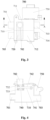
Figure 1 is a schematic diagram of the waterway communication structure of the control valve assembly in the embodiment of the present disclosure when the switching mechanism is in the first position; -
Figure 2 is a schematic diagram of the waterway communication structure of the control valve assembly in the embodiment of the present disclosure when the switching mechanism is in the second position; -
Figure 3 is a schematic structural diagram of the control valve assembly in the embodiment of the present disclosure (the switching mechanism is in the second position); -
Figure 4 is a schematic diagram of the AA section inFigure 3 of the present disclosure; -
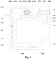
Figure 5 is a schematic structural diagram of a washing machine in an embodiment of the present disclosure; -
Figure 6 is a flow chart of the control method in Embodiment 1 of the present disclosure; -
Figure 7 is an enlarged schematic view of B inFigure 5 of the present disclosure; -
Figure 8 is a schematic structural diagram of the filtering device in Embodiment 3 of the present disclosure; -
Figure 9 is a schematic view of the CC section inFigure 8 of the present disclosure. - In the picture: 10. box body; 100. water container; 110. window gasket; 210. drainage pipeline; 220. circulation pipeline; 230. return water pipeline; 231. return water control valve; 240. sewage pipeline; 250. discharge pipeline; 260. water container drainage pipe; 280. connecting pipeline; 300. detergent box; 400. pump assembly; 500. recovery device; 501. filtered impurities; 510. housing; 520, filter component; 531. first chamber; 532. second chamber;
- 600. filtering device; 601. first limiting surface; 602. second limiting surface; 603. third limiting surface; 604. fourth limiting surface; 605. fifth limiting surface; 606. sixth limiting surface surface; 610. filtering cavity; 6101. water inlet; 6102. filtered water outlet; 6103. sewage outlet; 6104. installation opening; 611. sealing support part; 612. sleeve part; 613. reinforcing rib; 620. filtering mechanism; 621. water outlet joint; 622. rotating support part; 623. filter support part; 624. motor mounting part; 625. filter screen; 631. first bearing; 632. second bearing; 641. first seal; 642. second seal; 643. third seal; 650. filtering cavity flange; 651. connection part; 652. insertion part; 653. through port; 660. driving mechanism; 680. cleaning particles;
- 700. control valve assembly; 701. water inlet; 702. circulating water outlet; 703. drainage outlet; 704. sewage inlet; 705. sewage outlet; 710. valve body; 711. first valve chamber; 712. second valve chamber; 720. switching mechanism; 732. circulation sealing component; 733. drainage sealing component; 740. flip; 741. first surface; 742. second surface; 750. driving motor.
- It should be noted that these drawings and text descriptions are not intended to limit the scope of the disclosure in any way, but are intended to illustrate the concept of the disclosure for those skilled in the art by referring to specific embodiments.
- In order to make the purpose, technical solutions and advantages of the embodiments of the present disclosure clearer, the technical solutions in the embodiments of the present disclosure will be clearly and completely described below in conjunction with the drawings in the embodiments of the present disclosure. The following examples are used to illustrate the present disclosure, but are not used to limit the scope of the present disclosure.
- In the description of the present disclosure, it should be noted that the terms "upper", "lower", "front", "back", "left", "right", "vertical", "inner", "outer", etc. The indicated orientation or positional relationship is based on the orientation or positional relationship shown in the drawings. It is only for the convenience of describing the present disclosure and simplifying the description. It does not indicate or imply that the device or element referred to must have a specific orientation or a specific orientation. construction and operation, and therefore should not be construed as limitations of the disclosure.
- In the description of the present disclosure, it should be noted that, unless otherwise clearly stated and limited, the terms "installation", "connection" and "connection" should be understood in a broad sense. For example, it can be a fixed connection or a detachable connection. Connection, or integral connection; it can be a mechanical connection or an electrical connection; it can be a direct connection or an indirect connection through an intermediate medium. For those of ordinary skill in the art, the specific meanings of the above terms in the present disclosure can be understood on a case-by-case basis.
- As shown in
FIGS. 1 to 5 , the washing machine in this embodiment includes: - a
water container 100; - a circulating filter pipeline, a water inlet end and a water outlet end of which are respectively connected with the
water container 100, and apump assembly 400 is provided on it; - a
filtering device 600 is provided on the circulating filter pipeline and has awater inlet 6101, a filteredwater outlet 6102 and asewage outlet 6103; - a
sewage pipeline 240 for receiving the sewage discharged from thesewage outlet 6103; and, - a
control valve assembly 700. - Specifically, control
valve assembly 700 includes: - a
valve body 710, which has afirst valve chamber 711 and asecond valve chamber 712 that are independent of each other. Thefirst valve chamber 711 is provided with awater inlet 701 connected to thepump assembly 400, and a circulatingwater outlet 702 connected to thewater inlet 6101. Thesecond valve chamber 712 is provided with asewage inlet 704 connected to thesewage outlet 6103, and asewage outlet 705 connected to thesewage pipeline 240; - a
switching mechanism 720, which is movably arranged inside thevalve body 710 and has a first position for opening the circulatingwater outlet 702 and blocking thesewage inlet 704, and a second position for blocking the circulatingwater outlet 702 and opening thesewage inlet 704. - In this embodiment, the
water inlet 701 of thefirst valve chamber 711 and thesewage outlet 705 of thesecond valve chamber 712 are open by default. When theswitching mechanism 720 is in the first position, thewater inlet 701 and the circulatingwater outlet 702 are both open, and thepump assembly 400 is connected to thewater inlet 6101 of thefiltering device 600; at the same time, thesewage inlet 704 is blocked, and thefiltering device 600 is disconnected from thesewage outlet 6103 and thesewage pipeline 240. - When the
switching mechanism 720 is in the second position, the circulatingwater outlet 702 is in a blocked state, and thepump assembly 400 is disconnected from thewater inlet 6101 of thefiltering device 600; at the same time, thesewage inlet 704 and thesewage outlet 705 are both open, and thesewage outlet 6103 of thefiltering device 600 is connected to thesewage pipeline 240. - The
control valve assembly 700 of this embodiment has two working states, corresponding to theswitching mechanism 720 being in different positions. Specifically, the first working state of thecontrol valve assembly 700 is that theswitching mechanism 720 is in the first position, connecting thepump assembly 400 and thewater inlet 6101 and disconnecting thesewage outlet 6103 and thesewage pipeline 240; the second working state of thecontrol valve assembly 700 is that theswitching mechanism 720 is in the second position, disconnecting thepump assembly 400 and thewater inlet 6101 and connecting thesewage outlet 6103 and thesewage pipeline 240. - In the above solution, the
control valve assembly 700 can simultaneously control the connection between thepump assembly 400 and thewater inlet 6101 of thefiltering device 600, and the connection between thesewage outlet 6103 of thefiltering device 600 and thesewage pipeline 240. By switching the working state of thecontrol valve assembly 700, thefiltering device 600 can be switched between the two working processes of filtration and sewage discharge. Thecontrol valve assembly 700 can simultaneously control the opening and closing of two relatively independent water channels, which is beneficial to simplifying the layout of the internal water channel structure of the washing machine and making the control logic of the water channel opening and closing simpler. - In this embodiment, the washing machine alternately performs the circulation filtering operation and the sewage discharge operation during the washing/rinsing process.
- Wherein, the circulation filtering operation includes: the
pump assembly 400 is in an open state, thecontrol valve assembly 700 is in the first working state, that is, thecontrol valve assembly 700 connects thepump assembly 400 and thewater inlet 6101 and disconnects thesewage outlet 6103 and thesewage pipeline 240, the water in thewater container 100 is circulated and filtered. - The sewage discharge operation includes: the
pump assembly 400 is in a closed state, thecontrol valve assembly 700 is in the second working state, that is, thecontrol valve assembly 700 disconnects thepump assembly 400 and thewater inlet 6101 and connects thesewage outlet 6103 and thesewage pipeline 240, and the sewage in thefiltering device 600 is discharged into thesewage pipeline 240. - In the above scheme, by alternately performing the circulation filtering operation and the sewage discharge operation during the washing/rinsing stage of the washing machine, the filtered impurities such as lint residues remaining inside the
filtering device 600 during the circulation filtering process can be discharged in a timely manner, thereby preventing the filtered impurities from being internal accumulation in thefiltering device 600, affecting the filtration efficiency. Especially when the content of filtered impurities such as lint in the water is high, the solution of this embodiment, compared with the method of continuously performing the circulation filtering operation until the end of washing/rinsing, effectively prevents excessive accumulation of filtered impurities, causing thefiltering device 600 to become clogged. - In this embodiment, the
pump assembly 400 may be a water pump that generates suction force to draw out the water in thewater container 100 for circulation filtration. - In a further solution of this embodiment, while the washing machine is performing a circulation filtering operation, the
pump assembly 400 is controlled to be turned on intermittently. Through the intermittent opening of thepump assembly 400, during the period when thepump assembly 400 is closed, the water in thewater container 100 pauses passing through thefiltering device 600, and the filtered impurities attached to the inside of thefiltering device 600 can fall off and merge into the water during this period, and then perform the sewage discharge operation. It is discharged with the water flow. This avoids the situation where the water flow is filtered through thefiltering device 600 for too long, causing the filtered impurities to adhere too firmly inside thefiltering device 600 and cannot be fully discharged during the sewage discharge operation. - It can be understood that increasing the frequency of alternate execution of circulation filtration operations and sewage discharge operations can also achieve the purpose of preventing filtered impurities from being too firmly attached. However, alternate execution of the circulation filtering operation and the sewage blowdown operation requires the
control valve assembly 700 to switch working states. For thecontrol valve assembly 700, too frequent switching of working states may result in shortened service life. - In this embodiment, by controlling the
pump assembly 400 to be turned on intermittently during the circulation filtering operation, thepump assembly 400 can be prevented from continuing to work for a long time, the service life of thepump assembly 400 can be extended, and thecontrol valve assembly 700 can be avoided from frequently switching. In the working state, thecontrol valve assembly 700 is protected. - In the specific solution of this embodiment, the circulation filtering operation includes the following steps:
- S 1. The
control valve assembly 700 being controlled to connects thepump assembly 400 and thewater inlet 6101 and disconnects thesewage outlet 6103 and thesewage pipeline 240; - S2. Turn on the
pump assembly 400 and continue for a certain period of time; - S3. Turn off the
pump assembly 400 for a certain period of time; - S4. If the number of times step S2 is performed in this circulation filtering operation reaches the preset number, end the circulation filtering operation; otherwise, return to step S2.
- Further, during the execution of a circulation filtering operation, the
pump assembly 400 continues to run for the first preset time period T1 after being turned on for the first time, and then continues to run for the second preset time period T2 after being turned on each time. The first preset time length T1 is greater than the second preset time length T2. - In the above solution, a filter screen is provided inside the
filtering device 600, and the filtering process is implemented through the mesh on the filter screen. The specific values of the first preset time length T1 and the second preset time length T2 can be obtained in advance through a large number of experiments and directly written into the control program of the washing machine. The first preset time length T1 is specifically that the length of time it takes for most of the mesh holes on the filter to be covered by filtered impurities during continuous filtration of thefiltering device 600. - In a circulation filtering operation, when the
pump assembly 400 is turned on for the first time, there are basically no filtered impurities attached to the filter screen, so the value of the first preset time period T1 can be larger. During the shutdown of thepump assembly 400, there is no guarantee that the filtered impurities attached to the filter screen will completely fall off. That is, every time thepump assembly 400 is turned on thereafter, some filtered impurities may be attached to the filter screen. Therefore, the value of the second preset time period T2 is less than the first preset time period T1 to avoid clogging of the filter screen and affecting the filtration process. - In this embodiment, the
filtering device 600 includes: - a
filtering cavity 610, which is provided with awater inlet 6101, a filteredwater outlet 6102 and asewage outlet 6103; - a
filtering mechanism 620, which is rotatably arranged in thefiltering cavity 610; - a
driving mechanism 660, which is used to drive thefiltering mechanism 620 to rotate in thefiltering cavity 610. - Step S3 also includes: while the
pump assembly 400 is closed, thedriving mechanism 660 is turned on to drive thefiltering mechanism 620 to rotate in thefiltering cavity 610. - Specifically, the
filtering mechanism 620 divides the interior of thefiltering cavity 610 into an outer cavity and an inner cavity, wherein thewater inlet 6101 is connected to the outer cavity, and the filteredwater outlet 6102 is connected to the inner cavity. The water in thewater container 100 enters the outer cavity through thewater inlet 6101 under the action of thepump assembly 400, and enters the inner cavity through thefiltering mechanism 620 to be filtered. The lint carried in the water adheres to the outer wall of thefiltering mechanism 620. - In this embodiment, the
driving mechanism 660 is turned on when thepump assembly 400 is closed. Thedriving mechanism 660 drives thefiltering mechanism 620 to rotate, which can stir the water flow in thefiltering cavity 610, so that the filtered impurities attached to the outer wall of thefiltering mechanism 620 are peeled off under the action of the combination of centrifugal force and agitation of the water flow, and blends into the water in thefiltering cavity 610, which helps the filtered impurities attached to the outer wall of thefiltering mechanism 620 to fully fall off. - In this embodiment, cleaning
particles 680 are further provided in thefiltering cavity 610. The cleaningparticles 680 are used to clean the inner wall of thefiltering cavity 610 and the outer wall of thefiltering mechanism 620 by friction and collision with the water flow. During the opening of thepump assembly 400, the water flow continues to pass through thefiltering device 600, and the cleaningparticles 680 are driven by the water flow to continuously rub against the inner wall of thefiltering cavity 610 and the outer wall of thefiltering mechanism 620, which can slow down the deposition of filtered impurities, thereby appropriately extending duration of continuous activation of thepump assembly 400. When thedriving mechanism 660 drives thefiltering mechanism 620 to rotate, the cleaningparticles 680 move with the water flow, which is conducive to further strengthening the agitation of the water flow, thereby making it easier for the attached filtered impurities to fall off. - Furthermore, in step S3 of this embodiment, the
filtering mechanism 620 continues to rotate while thepump assembly 400 is closed, and each time thedriving mechanism 660 is turned on, thefiltering mechanism 620 continues to rotate for the same length of time. - Preferably, the continuous rotation time of the
filtering mechanism 620 in step S3 is the third preset time length T3, and the third preset time length T3 is less than the second preset time length T2.
the third preset time period T3 can be obtained in advance through a large number of experiments and directly written into the control program of the washing machine to ensure that filtered impurities such as lint and other lint attached to thefiltering mechanism 620 can be fully shed. - In a further solution of this embodiment, the washing machine further includes a
discharge pipeline 250 for draining water to the outside. Thecontrol valve assembly 700 not only connects thesewage outlet 6103 and thesewage pipeline 240, but also connects thepump assembly 400 with thedischarge pipeline 250. - Specifically, the
first valve chamber 711 of thecontrol valve assembly 700 is provided with adrainage outlet 703 that communicates with thedischarge pipeline 250. In the first working state of thecontrol valve assembly 700, that is, when theswitching mechanism 720 is in the first position, theswitching mechanism 720 blocks thedrainage outlet 703. In the second working state of thecontrol valve assembly 700, theswitching mechanism 720 is in the second position and thedrainage outlet 703 is opened. - After the washing/rinsing process is completed, the
control valve assembly 700 connects thepump assembly 400 and thedischarge pipeline 250, opens thepump assembly 400, and the water in thewater container 100 is discharged from the washing machine through thedischarge pipeline 250. - In detail, the circulating filter pipeline of the washing machine in this embodiment specifically includes:
- a water
container drain pipe 260, which connects thewater container 100 and the water inlet end of thepump assembly 400; - a
drainage pipeline 210, one end of which is connected to the water outlet end of thepump assembly 400 and the other end is connected to thewater inlet 701 of thecontrol valve assembly 700; - a
circulation pipeline 220, one end of which is connected to the circulatingwater outlet 702 of thecontrol valve assembly 700 and the other end connected to thewater inlet 6101 of thefiltering device 600; - a
return water pipeline 230, one end of which is connected to the filteredwater outlet 6102 of thefiltering device 600, and the other end is connected to thewater container 100 to transport the filtered water to thewater container 100; - a
discharge pipeline 250, one end of which is connected to thedrainage outlet 703 of thecontrol valve assembly 700, and the other end leads to the outside of the washing machine. - In the above solution, the
pump assembly 400 is used for both circulating filtration of water in thewater container 100 and for draining water from the washing machine. Moreover, the circulating filtration and drainage share part of the pipeline structure, which simplifies the layout of the waterway structure inside the washing machine and is beneficial to save space inside the washing machine. - After the washing/rinsing is completed, the
control valve assembly 700 switches to the second working state, so that between thewater inlet 701 and thedrainage outlet 703 of thefirst valve chamber 711, and between thesewage inlet 704 and thesewage outlet 705 of thesecond valve chamber 712 are simultaneously communicated. Thewater container 100 drains to the outside of the washing machine, at the same time, thesewage outlet 6103 of thefiltering device 600 is communicated to thesewage pipeline 240, so that the sewage in thefiltering device 600 can be continuously discharged while draining, ensuring the discharge rate of sewage. On the other hand, the drainage of thewater container 100 and the drainage of thefiltering device 600 are performed at the same time, which improves the working efficiency of the washing machine and improves the user experience. - In this embodiment, the
return water pipeline 230 is specifically connected to thewindow gasket 110 at the opening of thewater container 100. - The
sewage outlet 6103 of thefiltering device 600 is connected to the connectingpipeline 280, the connectingpipeline 280 is connected to thesewage inlet 704 of thecontrol valve assembly 700, and the water inlet end of thesewage pipeline 240 is connected to thesewage outlet 705 of thecontrol valve assembly 700, forming a discharge channel of sewage in thefiltering device 600. - Preferably, a return
water control valve 231 is provided on thereturn water pipeline 230 for controlling the opening and closing of thereturn water pipeline 230. When thecontrol valve assembly 700 is switched to the second working state, the returnwater control valve 231 is closed to cut off thereturn water pipeline 230 to ensure that the water in thefiltering cavity 610 will not flow out from the filteredwater outlet 6102, which is beneficial to discharging the filtered impurities residual in thefiltering device 600 with the water flow. - The
control valve assembly 700 in this embodiment is shown inFIGS. 3 and 4 , where theswitching mechanism 720 includes: - a
flap 740, which is rotatably installed inside thevalve body 710 and has opposite afirst surface 741 and asecond surface 742; - a
drainage sealing component 733, which is provided on thefirst surface 741 of theflap 740 and is located inside thefirst valve chamber 711 for blocking thedrainage outlet 703; - a sewage sealing component is disposed on the
first surface 741 of theflap 740 and located inside thesecond valve chamber 712 for blocking thesewage inlet 704; - a
circulation sealing component 732 is disposed on thesecond surface 742 of theflap 740 and is located inside thefirst valve chamber 711 for blocking thecirculation water outlet 702. - The
drainage outlet 703 and thesewage inlet 704 are provided on the same side surface of thevalve body 710. When theswitching mechanism 720 is in the first position, thedrainage sealing component 733 and the sewage sealing component block thedrainage outlet 703 and thesewage inlet 704 respectively; when theswitching mechanism 720 is in the second position, theflap 740 moves away from thedrainage outlet 703 and thesewage inlet 704 relative to the previous state until thecirculation sealing component 732 blocks thecirculation water outlet 702. - The
flap 740 is connected to a drivingmotor 750 for driving theflap 740 to rotate in thevalve body 710. The drivingmotor 750 is arranged outside thevalve body 710, which avoids the risk of contact with water and is safer. Thecontrol valve assembly 700 drives theflap 740 to move through the drivingmotor 750, and can simultaneously control the opening/blocking switching of the circulatingwater outlet 702, thedrainage outlet 703 and thesewage inlet 704, and has a simple structure. Compared with the existing solution in which a driven control valve is provided for each independent waterway, the cost is effectively saved. - In this embodiment, the
first valve chamber 711 and thesecond valve chamber 712 of thecontrol valve assembly 700 extend in a left and right direction and are arranged parallel to each other. Thedrainage outlet 703 is disposed on the right end cavity wall of thefirst valve chamber 711 in the length direction, and thesewage inlet 704 is disposed on the right end cavity wall of thesecond valve chamber 712. - Preferably, the
water inlet 701 is provided on the left end wall of thefirst valve chamber 711, parallel to and opposite to the direction of thedrainage outlet 703. Thesewage outlet 705 is disposed on the left end wall of thesecond valve chamber 712, parallel to and opposite to the direction of thesewage inlet 704. When thecontrol valve assembly 700 is in the second working state, the water flows from left to right in thefirst valve chamber 711 and from right to left in thesecond valve chamber 712, thus the resistance of the water flow is small. The washing machine drainage and the sewage discharge of thefiltering device 600 is smoother. - The direction of the circulating
water outlet 702 and the direction of thedrainage outlet 703 are perpendicular to each other. Thecontrol valve assembly 700 switches from the first working state to the second working state. Theflap 740 rotates 90° around its axis to move from the first position to the second position. - Specifically, in this embodiment, taking the orientation in
FIG. 3 as an example, thefirst valve chamber 711 is disposed above thesecond valve chamber 712, and the circulatingwater outlet 702 is disposed on the front wall of thefirst valve chamber 711. - When the
switching mechanism 720 is in the first position, theflap 740 is nearly parallel to the right end walls of thefirst valve chamber 711 and thesecond valve chamber 712, so that thedrainage sealing component 733 blocks thedrainage outlet 703, and the drainage sealing component blocks the sewage inlet. 704. When theswitching mechanism 720 moves from the first position to the second position, the drivingmotor 750 drives theflap 740 to rotate forward 90° , causing thecirculation sealing component 732 to block thecirculation water outlet 702. At this time, thedrainage sealing component 733 is separated from thedrainage outlet 703, and thedrainage outlet 703 is opened; the drainage sealing component is separated from thesewage inlet 704, and thesewage inlet 704 is opened. - In a further solution of this embodiment, before washing/rinsing water enters, the
control valve assembly 700 is switched to the first working state, that is, thepump assembly 400 and thewater inlet 6101 are connected and thesewage outlet 6103 and thesewage pipeline 240 are disconnected;
starting to feed water into thewater container 100, after the water level in thewater container 100 is greater than the preset water level, thepump assembly 400 is turned on to perform a circulating filtration operation, and after the circulating filtration operation is completed, a sewage discharge operation is performed; - The circulating filtration operation and the sewage discharge operation are executed alternately until the washing/rinsing process is completed.
- In the circulating filtration operation of this embodiment, the preset number of times described in step S4 is set to 3 times. That is, in one cycle of filtering operation, the washing machine turns on and off the
pump assembly 400 three times, and when thepump assembly 400 is turned off for the third time, and after thedriving mechanism 660 is turned on to drive thefiltering mechanism 620 to continue to rotate in thefiltering cavity 610 for the third preset time T3, thecontrol valve assembly 700 switches to the second working state to perform the sewage operation. -
Figure 6 shows a flow chart of the washing machine in this embodiment running a complete washing program, which includes the following steps: - 1) turning on the washing machine;
- 2) switching the control valve assembly to the first working state and communicating the circulating filtration pipeline;
- 3) starting to supply washing water;
- 4) turning on the pump assembly and continue for a first preset time T1;
- 5) turning off the pump assembly, and turning on the driving mechanism and continue for a third preset time T3;
- 6) turning off the driving mechanism, and turning on the pump assembly and continue for a second preset time T2;
- 7) turning off the pump assembly, and turning on the driving mechanism and continue for a third preset time T3;
- 8) turning off the driving mechanism, and turning on the pump assembly and continue for the second preset time T2;
- 9) turning off the pump assembly, and turning on the driving mechanism and continue for the third preset time T3;
- 10) turning off the driving mechanism, and switching the control valve assembly to the second working state, and the filtering device discharges sewage;
- 11) repeating step 4) to step 10) until the washing process is completed;
- 12) switching the control valve assembly to the second working state, and turning on the pump assembly, and the washing machine starting to drain water outward;
- 13) starting to supply rinsing water after drainage is completed;
- 14) repeating step 4) to step 10) until the rinsing process is completed;
- 15) switching the control valve assembly to the second working state, and turning on the pump assembly, and the washing machine starting to drain water outward;
- 16) executing dehydration after drainage is completed;
- 17) after the dehydration is completed and the washing program ends.
- In this embodiment, the washing machine alternately performs circulating filtration operation and sewage discharge operation during the washing and rinsing processes, which can timely discharge the filtered impurities remaining inside the
filtering device 600 through thesewage outlet 6103 to avoid accumulation of filtered impurities affecting the filtration efficiency. During the process of executing the circulating filtration operation, thepump assembly 400 is controlled to be turned on intermittently, and during the period when thepump assembly 400 is turned off, thefiltering mechanism 620 is driven to rotate by driving thedriving mechanism 660, so that filtered impurities such as lint and other lint attached to thefiltering mechanism 620 are fully shed, and then the sewage is fully discharged during execution of the operation. Through the above process, thefiltering device 600 can perform self-cleaning at any time during the running of the washing program, thereby avoiding the clogging of thefiltering device 600 and ensuring the water filtration efficiency of the washing machine. - Through the structural design of the
control valve assembly 700, a drivingmotor 750 can be used to control the water pumped out by thepump assembly 400 to be transported to thefiltering device 600 or to theoutflow pipeline 250, and at the same time control whether thesewage outlet 6103 of thefiltering device 600 discharges sewage to the outside. The washing machine's circulating filtering operation, sewage discharge operation, and drainage operation are all controlled by the samecontrol valve assembly 700. The internal water circulating structure of the washing machine is simplified, which saves more space and reduces costs. - As shown in
FIGS. 5 and7 , this embodiment is a further limitation of the above-mentioned Embodiment 1. The washing machine further includes arecovery device 500. Therecovery device 500 is connected to the water outlet end of thesewage pipeline 240 and is used to collect sewage discharged from thefiltering device 600. - Specifically, the
recovery device 500 is used to collect filteredimpurities 501 such as lint that are discharged with the sewage. - There may be fine lint in the filtered
impurities 501. If the sewage carrying the filteredimpurities 501 is directly poured into the drainage water of the washing machine and drained away with the washing machine, the fine lint will enter the ecological cycle, thereby causing harm to the ecological environment and human body. - The washing machine of this embodiment is equipped with a
recovery device 500. After the sewage carrying filteredimpurities 501 is discharged from thesewage outlet 6103, it can enter therecovery device 500 through thesewage pipeline 240 and be collected, without entering the drainage water flow and being discharged with the drainage water flow out of the washing machine. - In a further solution of this embodiment, the
recovery device 500 includes: - a
housing 510 with a recovery chamber inside; - a
filter component 520, which is disposed in the recovery chamber and divides the recovery chamber into afirst chamber 531 and asecond chamber 532. - The
sewage outlet 6103 of thefiltering device 600 is connected to thefirst chamber 531. The sewage carrying the filteredimpurities 501 enters thefirst chamber 531 and is filtered by thefilter component 520 before entering thesecond chamber 532, and the filteredimpurities 501 are collected in thefirst chamber 531. - In the above solution, the
filter component 520 is provided in therecovery device 500 to filter the sewage discharged from thefiltering device 600 and separate the filteredimpurities 501 therein from the water. The interior of therecovery device 500 is divided into afirst chamber 531 and asecond chamber 532 by thefilter component 520. The filteredimpurities 501 in the sewage are blocked by thefilter component 520, thereby collecting the filteredimpurities 501 on the upper surface of thefilter component 520 in thefirst chamber 531 , the filtered clean water is collected in thesecond chamber 532. Users can directly collect and process the separated filteredimpurities 501, avoiding the situation where the filteredimpurities 501 are mixed in water and cannot be effectively processed. - Specifically, the
filter component 520 can be a frame horizontally arranged at a certain height in the recovery chamber and a filter screen laid on the frame. After the sewage carrying filteredimpurities 501 enters thefirst chamber 531, the water can enter thesecond chamber 532 through thefilter component 520. The filteredimpurities 501 are blocked by the filter screen and remain on the upper surface of thefilter component 520. - In this embodiment, the washing machine further includes a
box body 10 in which thewater container 100 and thefiltering device 600 are disposed. Therecovery device 500 is installed on thebox body 10 in an insertable/extractable manner, and the user can withdraw therecovery device 500 from thebox body 10 for cleaning. - Specifically, the
housing 510 of therecovery device 500 is disposed on thebox body 10 so as to be insertable/extractable, and the upper side of thehousing 510 has an opening. When the user pulls out thehousing 510 from thebox body 10 , the filteredimpurities 501 attached to the upper surface of thefilter component 520 can be cleaned through the opening on the upper side of thehousing 510. Thefilter component 520 is preferably detachably connected to thehousing 510. The user can detach thefilter component 520 from the inside of thehousing 510 and take it out for cleaning, which makes the operation more convenient. - In a preferred solution of this embodiment, a water outlet is provided on the
second chamber 532 for discharging filtered clean water. By arranging a water outlet in thesecond chamber 532, the clean water entering thesecond chamber 532 can be discharged from therecovery device 500 in a timely manner, thus preventing therecovery device 500 from overflowing when a large amount of sewage is discharged from thefiltering device 600. Otherwise, the capacity of thesecond chamber 532 needs to be increased, that is, the volume of therecovery device 500 needs to be increased, causing it to occupy a larger space inside the washing machine, which is not conducive to miniaturization of the overall volume of the washing machine. - On the other hand, the water in the
second chamber 532 can be automatically discharged from the water outlet. When the user cleans therecovery device 500, he only needs to clean the filteredimpurities 501 on thefilter component 520 without manually pouring out the clear water of thesecond chamber 532. When thefilter component 520 is detachably installed in thehousing 510, the user does not even need to completely remove thehousing 510 from the washingmachine box body 10, but only needs to take out thefilter component 520 for cleaning, which is more convenient to operate. - In a preferred solution of this embodiment, the water outlet of the
second chamber 532 is connected to thewater container 100, and the water collected in thesecond chamber 532 is transported to thewater container 100. For example, the water outlet of thesecond chamber 532 can be connected to thereturn water pipeline 230, or directly connected to thewater container 100 through the pipeline. Alternatively, the water outlet of thesecond chamber 532 is connected to thedetergent box 300 on each side of therecovery device 500. Since thedetergent box 300 and thewater container 100 are connected through pipelines, the water collected in thesecond chamber 532 can pass through thedetergent box 300 enters thewater container 100. - Since the sewage entering the
recovery device 500 has been filtered by thefilter component 520 in therecovery device 500, the filteredimpurities 501 have been removed, and the clean water collected in thesecond chamber 532 does not contain the filteredimpurities 501. By sending it into thewater container 100, this part of clean water can be reused, thereby reducing the amount of water required when the washing machine continues to operate, and achieving the purpose of saving water consumption of the washing machine. - In another preferred solution of this embodiment, the water outlet of the
second chamber 532 may directly or indirectly lead to the outside of the washing machine. For example, the water outlet of thesecond chamber 532 is connected to theouter discharge pipeline 250 through a pipeline, and the water collected in thesecond chamber 532 is discharged from the washing machine through theouter discharge pipeline 250 . - Since the clean water collected in the
second chamber 532 does not contain the filteredimpurities 501, directly discharging it will not cause the problem of fine lint particles entering the ecological cycle. - In this embodiment, the
recovery device 500 is provided inside the washing machine. The sewage containing filteredimpurities 501 discharged by thefiltering device 600 can be passed into therecovery device 500 after passing through the connectingpipeline 280, thecontrol valve assembly 700 and thesewage pipe 240 in sequence. It is collected and discharged directly without flowing into the drain water of the washing machine. This prevents the fine lint debris in the filteredimpurities 501 from entering the ecological cycle with the drainage water and affecting the ecological environment and human health. Thefilter component 520 is provided in therecovery device 500 to filter the collected sewage, thereby separating the filteredimpurities 501 from water to facilitate the cleaning of the filteredimpurities 501. - As shown in
FIGS. 8 and9 , this embodiment is a further limitation of thefiltering device 600 in the embodiment 1 or 2. The outer circumference of the filteredwater outlet 6102 of thefiltering device 600 extends toward the outside of thefiltering cavity 610 to form a sealingsupport part 611, one end of thefiltering mechanism 620 has a water outlet joint 621 inserted in the sealingsupport part 611, and the wateroutlet j oint 621 is rotatably and sealingly connected to the sealingsupport part 611. Thefirst bearing 631 is sleeved on the water outlet joint 621. Afirst seal 641 is provided on the side of thefirst bearing 631 facing the inside of thefiltering cavity 610 for blocking the gap between the water outlet joint 621 and the sealingsupport part 611. - Specifically, the
filtering mechanism 620 includes a filter holder and afilter screen 625, wherein the filter holder includes: - a
filter support part 623, which is located inside thefiltering cavity 610, and thefilter screen 625 covers the surface of thefilter support part 623; - a water outlet joint 621, which is provided at the left end of the
filter support part 623, and is rotatably inserted into the sealingsupport part 611; - a
rotating support part 622 is provided at the right end of thefilter support part 623 and is rotatably connected to thefiltering cavity 610. - In the above solution, a
first bearing 631 is provided between the water outlet joint 621 and the sealingsupport part 611 to support the water outlet joint 621, so that the water outlet joint 621 rotates more smoothly in the sealingsupport part 611, and at the same time, the structure is stable, which can ensure filtration. Thefiltering mechanism 620 rotates stably in thefiltering cavity 610. Afirst seal 641 is provided on the right side of thefirst bearing 631 so that the washing water in thefiltering cavity 610 cannot enter the gap between the water outlet joint 621 and the sealingsupport part 611, thus preventing thefirst bearing 631 from contacting water and avoiding the failure of thefirst bearing 631 which ensures the effect of thefirst bearing 631. At the same time, thefirst seal 641 also prevents unfiltered wash water from flowing out from the filteredwater outlet 6102 through the sealingsupport part 611 and affecting the efficiency of thefiltering device 600 in removing lint. - In the specific solution of this embodiment, the
first seal 641 is sleeved on the water outlet joint 621, the inner wall of thefirst seal 641 is sealingly connected to the outer wall of the water outlet joint 621, and the outer wall of thefirst seal 641 is rotatably connected to the inner wall of the sealingsupport part 611 in a sealed manner. - In a further solution of this embodiment, the
filtering device 600 also includes asecond seal 642. Thesecond seal 642 is disposed on the side of thefirst bearing 631 facing away from the inside of thefiltering cavity 610, blocking the gap between the water outlet joint 621 and the sealingsupport part 611. - Specifically, the
second seal 642 is sleeved on the water outlet joint 621, the inner wall of thesecond seal 642 is sealingly connected to the outer wall of the water outlet joint 621, and the outer wall of thesecond seal 642 is rotatably connected with the inner wall of the sealingsupport part 611 in a sealed manner. - In the above solution, the water flowing out through the water outlet joint 621 can be blocked by the
second seal 642 and will not contact thefirst bearing 631. Thefirst bearing 631 is disposed between thefirst seal 641 and thesecond seal 642 to ensure that the installation environment of thefirst bearing 631 is water-free to the greatest extent, preventing thefirst bearing 631 from rusting when exposed to water and affecting the rotation of thefiltering mechanism 620. - In a further solution of this embodiment, the inner wall of the sealing
support part 611 has a stepped structure. From one end of the sealingsupport part 611 to the outside of thefiltering cavity 610, a first limitingsurface 601, a second limitingsurface 602 and a third limitingsurface 603 with an annular structure and gradually decreasing inner diameters are formed. - The surface of the
first seal 641 facing the outside of thefiltering cavity 610 is in contact with the first limitingsurface 601. The surface of thefirst bearing 631 facing the outside of thefiltering cavity 610 is in contact with the second limitingsurface 602. The surface of thesecond seal 642 facing the outside of thefiltering cavity 610 is in contact with the third limitingsurface 603. - In the above solution, a plurality of vertical annular limiting surfaces are formed by the inner wall of the sealing
support part 611 with a stepped structure, respectively abutting the left side surfaces of thefirst seal 641, thefirst bearing 631 and thesecond seal 642, which can limit the movement of the above three in the axial direction of the water outlet joint 621, and prevent the matching structure between the water outlet joint 621 and the sealingsupport part 611 from loosening during the rotation of thefiltering mechanism 620. - In the preferred solution of this embodiment, the outer diameter of one end of the water outlet joint 621 close to the outside of the
filtering cavity 610 is smaller than the outer diameter of the other end. A fourth limitingsurface 604 with annular structure is formed on the outer wall of the water outlet joint 621 and is perpendicular to the axis of the water outlet joint 621. The surface of thefirst bearing 631 facing the inside of thefiltering cavity 610 is in contact with the fourth limitingsurface 604. - By arranging the outer diameter of the left end of the water outlet joint 621 to be smaller than the right end, the fourth limiting
surface 604 toward the left is formed at the sudden change in the outer diameter, and is in contact with the right surface of thefirst bearing 631. In this way, both sides of thefirst bearing 631 have limiting structures, making the structure more stable. - In this embodiment, one end of the sealing
support part 611 away from thefiltering cavity 610, that is, the left end of the sealingsupport part 611 is connected to thefiltering cavity flange 650. Thefiltering cavity flange 650 has a throughport 653 in the middle that communicates with the water outlet joint 621. The outer periphery of the throughport 653 extends away from the sealingsupport part 611 to form aconnection part 651. - Preferably, the surface of the
filtering cavity flange 650 facing the sealingsupport part 611 has a raised plug-inpart 652, and the plug-inpart 652 is inserted into the opening at the left end of the sealingsupport part 611. - In the above solution, the left end of the sealing
support part 611 is connected to thefiltering cavity flange 650, and aconnection part 651 is formed on thefiltering cavity flange 650. The outer diameter of theconnection part 651 is smaller than the outer diameter of the sealingsupport part 611, and the inner diameter of theconnection part 651 is preferably equal to the inner diameter of the water outlet joint 621. When thefiltering device 600 is installed in the washing machine, it is connected to the return water pipeline through theconnection part 651 on thefiltering cavity flange 650. Compared with the way in which the return water pipeline is directly connected to the left end of the sealingsupport part 611, the installation is easier. - The right side of the
filtering cavity flange 650 has aninsertion part 652 inserted into the left end opening of the sealingsupport part 611 to facilitate positioning when thefiltering cavity flange 650 and the sealingsupport part 611 are assembled. A number of fixing parts are respectively provided on the outer periphery of thefiltering cavity flange 650 and the sealingsupport part 611, and screws are passed through the fixing parts to realize the fixation of thefiltering cavity flange 650 and the sealingsupport part 611. - In a further solution of this embodiment, the
rotating support part 622 at the right end of thefiltering mechanism 620 extends along its rotation axis toward the outside of thefiltering cavity 610. Thefiltering cavity 610 is provided with aninstallation opening 6104 for therotating support part 622 to pass through. Therotating support part 622 is rotatably and sealingly connected to theinstallation opening 6104. - In this embodiment, the
filtering mechanism 620 is driven to rotate by the driving mechanism. In order to prevent the driving mechanism from contacting the washing water, the driving mechanism is arranged outside thefiltering cavity 610. To this end, therotating support part 622 extends from the right end of thefiltering cavity 610, and amotor mounting part 624 is provided at the right end of therotating support part 622 for connection with a driving mechanism, such as a motor. - Further, the outer periphery of the
installation opening 6104 extends along the axis of therotating support part 622 to form asleeve part 612 out of thefiltering cavity 610. Thethird seal 643 is sleeved on therotating support part 622. The inner wall of thethird seal 643 is sealingly connected to the outer wall of therotating support part 622, and the outer wall of thethird seal 643 is rotatably sealingly connected to the inner wall of thesleeve part 612. - A
second bearing 632 is also provided between thesleeve part 612 and therotating support part 622. Thesecond bearing 632 is sleeved on therotating support part 622 and is located on the side of thethird seal 643 facing the outside of thefiltering cavity 610. - In the above solution, the arrangement of the
third seal 643 prevents the water in thefiltering cavity 610 from leaking from theinstallation opening 6104, and the arrangement of thesecond bearing 632 can support therotating support part 622 to ensure that the relative rotation between therotating support part 622 and thesleeve part 612 is smoother. Thesecond bearing 632 is disposed on the right side of thethird seal 643 and is not in contact with the water in thefiltering cavity 610 to avoid failure. - In the preferred solution of this embodiment, the inner diameter of one end of the
sleeve part 612 close to the outside of thefiltering cavity 610 is smaller than the inner diameter of the other end. A fifth limitingsurface 605 with annular structure is formed on the inner wall of thesleeve part 612 and is perpendicular to the axis of therotating support part 622. The surface of thethird seal 643 facing the outside of thefiltering cavity 610 is in contact with the fifth limitingsurface 605. - The outer diameter of one end of the
rotating support part 622 close to the outside of thefiltering cavity 610 is smaller than the outer diameter of the other end. A sixth limitingsurface 606 with an annular structure and perpendicular to the axis of therotating support part 622 is formed on the outer wall of therotating support part 622. The surface of thesecond bearing 632 facing the inside of thefiltering cavity 610 is in contact with the sixth limitingsurface 606. - In the above solution, the inner diameter of the right end of the
sleeve part 612 is smaller than the inner diameter of the left end, and the fifth limitingsurface 605 toward the left is formed at a sudden change in the inner diameter to contact the right surface of thethird seal 643. The outer diameter of the right end of therotating support part 622 is smaller than the outer diameter of the left end, and a sudden change in the outer diameter forms a sixth limitingsurface 606 toward the right, which contacts the left surface of thesecond bearing 632. The above structure limits the movement of thethird seal 643 and thesecond bearing 632 in the axial direction of therotating support part 622, and the structure is stable. - In this embodiment, the
first seal 641, thesecond seal 642 and thethird seal 643 are all oil seals, and the right wall of thefiltering cavity 610 is provided separately from its peripheral side wall. First, thefiltering mechanism 620, as well as thefirst seal 641, thesecond seal 642 and thefirst bearing 631 at its left end are integrally installed inside thefiltering cavity 610, and thethird seal 643 and thesecond bearing 632 are installed at its right end, and finally fasten the right wall of thefiltering cavity 610 with its peripheral side wall. - In this embodiment, the cross-sectional area of the middle region of the
filter support part 623 is constant, and its left and right ends have tapered structures, so that the partial surface of thefilter screen 625 is tilted, which is beneficial to the shedding of attached lint. - In this embodiment, the orientation of the
water inlet 6101 and thesewage outlet 6103 on thefiltering cavity 610 is perpendicular to the axial direction of thefiltering mechanism 620. - Preferably, the
filtering cavity 610 has a cylindrical structure, thewater inlet 6101 is located near the right end of thefiltering cavity 610, thesewage outlet 6103 is located near the left end of thefiltering cavity 610, and thewater inlet 6101 and thesewage outlet 6103 are symmetrical in circumferential position of thefiltering cavity 610. - In the above solution, the
water inlet 6101 is positioned as far away from the water outlet joint 621 as possible so that the area of thefilter screen 625 can be fully utilized. Thewater inlet 6101 and thesewage outlet 6103 are arranged up and down, and are staggered in the axial direction of thefiltering cavity 610, which is conducive to fully discharging the sewage after cleaning thefiltering device 600 in thefiltering cavity 610. - In a further solution of this embodiment, the outer wall of the sealing
support part 611 is provided with reinforcingribs 613 extending in the radial direction of the sealingsupport part 611, and the reinforcingribs 613 are connected to the surface of thefiltering cavity 610 where the filteredwater outlet 6102 is located. - Since the sealing
support part 611 extends to a certain length from the left end surface of thefiltering cavity 610, the reinforcingribs 613 are provided to support its peripheral side wall from the outside, ensuring the strength of the sealingsupport part 611. - In the
filtering device 600 of this embodiment, thefirst bearing 631 and thesecond bearing 632 are respectively provided at both ends of thefiltering mechanism 620 for support, which ensures that thefiltering mechanism 620 rotates smoothly and stably in thefiltering cavity 610. At the same time, through the arrangement of thefirst seal 641, thesecond seal 642 and thethird seal 643, thefirst bearing 631 and thesecond bearing 632 are prevented from being in contact with water, thereby avoiding failure. - The above are only preferred embodiments of the present disclosure, and do not limit the present disclosure in any form. Although the present disclosure has been disclosed above in preferred embodiments, it is not intended to limit the present disclosure. Anyone familiar with the technology of this patent without departing from the scope of the technical solution of the present disclosure, personnel can make some changes or modify the above-mentioned technical contents into equivalent embodiments with equivalent changes. In essence, any simple modifications, equivalent changes and modifications made to the above embodiments still fall within the scope of the present disclosure.
Claims (10)
- A control method for a washing machine, the washing machine comprising:a water container;a circulating filtration pipeline, with a water inlet end and a water outlet end of the circulating filtration pipeline being connected to the water container respectively, and a pump assembly being installed thereon;a filtering device, being configured to install on the circulating filtration pipeline and to have a water inlet, a filtered water outlet and a sewage outlet;a sewage pipeline, being configured to receive sewage discharged from the sewage outlet; anda control valve assembly; characterized in that,during a washing or a rinsing process, the washing machine alternately executes:a circulating filtration operation, in which the pump assembly is in an open state, the control valve assembly connects the pump assembly and the water inlet and disconnects the sewage outlet and the sewage pipeline to perform a circulating filtration of water in the water container; anda sewage discharge operation, in which the pump assembly is in a closed state, the control valve assembly disconnects the pump assembly and the water inlet and connects the sewage outlet and the sewage pipeline, and the sewage in the filtering device is discharged into the sewage pipeline.
- The control method for the washing machine according to claim 1, characterized in that, during the circulating filtration operation, the pump assembly is controlled to be turned on intermittently;
preferably, the circulating filtration operation includes the following steps:S 1. the control valve assembly connecting the pump assembly and the water inlet and disconnecting the sewage outlet and the sewage pipeline;S2. turning on the pump assembly and continue for a certain period of time;S3. turning off the pump assembly and continue for a certain period of time;S4. if step S2 is performed a number of times in the circulating filtration operation reaches a preset number of times, end the circulating filtration operation; otherwise, returning to step S2. - The control method for the washing machine according to claim 2, characterized in that, during the circulating filtration operation, the pump assembly continues to operate for a first preset time period T1 after being turned on for a first time, and the pump assembly continues to operate for a second preset time length T2 after each subsequent turn on; the first preset time length T1 is greater than the second preset time length T2.
- The control method for the washing machine according to claim 2 or 3, characterized in that the filtering device includes:a filtering cavity, being configured to arrange the water inlet, the filtered water outlet and the sewage outlet;a filtering mechanism, being rotatably installed in the filtering cavity;a driving mechanism, being configured to drive the filtering mechanism to rotate in the filtering cavity;Step S3 further includes: while the pump assembly is closed, turning on the driving mechanism to drive the filtering mechanism to rotate in the filtering cavity.
- The control method for the washing machine according to claim 4, characterized in that in step S3, the filtering mechanism continues to rotate while the pump assembly is turned off, and each time the driving mechanism is turned on, the filtering mechanism continues to rotate for a same length of time;
preferably, in step S2, the pump assembly continues to operate at least the second preset time length T2 after being turned on, in step S3, the filtering mechanism continues to operate a third preset time length T3, and the third preset time length T3 is less than the second preset time length T2. - The control method for the washing machine according to any one of claims 1 to 5, characterized in that, the washing machine further includes a discharge pipeline for draining water to outside, and the control valve assembly connects the sewage outlet and the sewage pipeline while connecting the pump assembly and the discharge pipeline;
after the washing or the rinsing process is completed, the control valve assembly connects the pump assembly and the discharge pipeline, turns on the pump assembly, and the water in the water container is discharged from the washing machine through the discharge pipeline. - The control method for the washing machine according to any one of claims 1 to 6, characterized in that, before water supply for the washing or the rinsing process, the control valve assembly connects the pump assembly and the water inlet and disconnects the sewage outlet and the sewage pipeline;starting to supply water into the water container, after a water level in the water container is greater than a preset water level, turning on the pump assembly to perform the circulating filtration operation, after the circulating filtration operation is completed, performing the sewage discharge operation;the circulating filtration operation and the sewage discharge operation are executed alternately until the washing or the rinsing process is completed.
- A washing machine, characterized in that, adopting the control method for the washing machine according to any one of claims 1-7.
- The washing machine according to claim 8, characterized in that, the control valve assembly comprising:a valve body, being configured to arrange a first valve chamber and a second valve chamber that are independent of each other in the valve body, wherein, the first valve chamber is provided with a water inlet connected to the pump assembly and a circulating water outlet connected to the water inlet; the second valve chamber is provided with a sewage inlet communicated with the sewage outlet and a sewage outlet communicated with the sewage pipeline;a switching mechanism, being movably arranged inside the valve body and being configured to have a first position for opening the circulating water outlet and blocking the sewage inlet, and a second position for blocking the circulating water outlet and opening the sewage inlet;preferably, the washing machine further includes a discharge pipeline for draining water to the outside, and the first valve chamber is further provided with a drainage outlet connected to the discharge pipeline;when the switching mechanism is in the first position, the drainage outlet is blocked, and when the switching mechanism is in the second position, the drainage outlet is opened.
- The washing machine according to claim 8 or 9, characterized in that, the filtering device comprising:a filtering cavity, being configured to arrange with the water inlet, the filtered water outlet and the sewage outlet;a filtering mechanism, being rotatably installed in the filtering cavity;cleaning particles, being arranged in the filtering cavity and being configured to clean an inner wall of the filtering cavity and an outer wall of the filtering mechanism with friction and collision of water flow.
Applications Claiming Priority (2)
| Application Number | Priority Date | Filing Date | Title |
|---|---|---|---|
| CN202111287493.8A CN116065339B (en) | 2021-11-02 | 2021-11-02 | A control method for a washing machine and the washing machine |
| PCT/CN2022/124557 WO2023078037A1 (en) | 2021-11-02 | 2022-10-11 | Washing machine control method and washing machine |
Publications (2)
| Publication Number | Publication Date |
|---|---|
| EP4411047A1 true EP4411047A1 (en) | 2024-08-07 |
| EP4411047A4 EP4411047A4 (en) | 2025-01-08 |
Family
ID=86170417
Family Applications (1)
| Application Number | Title | Priority Date | Filing Date |
|---|---|---|---|
| EP22889063.8A Pending EP4411047A4 (en) | 2021-11-02 | 2022-10-11 | Washing machine control method and washing machine |
Country Status (6)
| Country | Link |
|---|---|
| US (1) | US20250059697A1 (en) |
| EP (1) | EP4411047A4 (en) |
| JP (1) | JP2024539359A (en) |
| CN (1) | CN116065339B (en) |
| AU (1) | AU2022381026B2 (en) |
| WO (1) | WO2023078037A1 (en) |
Families Citing this family (1)
| Publication number | Priority date | Publication date | Assignee | Title |
|---|---|---|---|---|
| CN120818963A (en) * | 2024-04-15 | 2025-10-21 | 青岛海尔洗衣机有限公司 | Control method of washing equipment and washing equipment |
Family Cites Families (15)
| Publication number | Priority date | Publication date | Assignee | Title |
|---|---|---|---|---|
| CN101760939A (en) * | 2008-10-23 | 2010-06-30 | 李哲平 | Water cycle utilization design for washing machine |
| CN103361938B (en) * | 2012-03-26 | 2016-05-25 | 海尔集团技术研发中心 | Water treatment facilities, processing method and washing machine in a kind of washing machine |
| CN103835095B (en) * | 2012-11-26 | 2017-03-22 | 海尔集团技术研发中心 | Clothes washing water recycling device, washing method thereof and water-saving clothes washing control method |
| JP2015091292A (en) * | 2013-04-16 | 2015-05-14 | パナソニックIpマネジメント株式会社 | Dryer |
| CN104294550A (en) * | 2013-06-28 | 2015-01-21 | 海尔集团技术研发中心 | Filter device, washing machine and washing control method |
| CN104372574B (en) * | 2013-08-15 | 2018-05-01 | 青岛海尔洗衣机有限公司 | It is a kind of that there is the washing machine of circulating water treatment and its control method |
| CN104711824B (en) * | 2013-12-12 | 2018-09-04 | 青岛海尔洗衣机有限公司 | A kind of water-conservation washing machine and control method |
| CN104894815B (en) * | 2014-03-06 | 2017-01-25 | 海尔集团技术研发中心 | Filter and washing machine with circulating water filter system |
| CN104975475B (en) * | 2014-04-09 | 2019-01-18 | 青岛海尔洗衣机有限公司 | A kind of filter mesh for washer self cleaning method and washing machine |
| CN105088642B (en) * | 2014-05-08 | 2019-04-05 | 青岛海尔洗衣机有限公司 | A kind of control method for washing machine and washing machine |
| CN105088697B (en) * | 2014-05-08 | 2019-01-29 | 青岛海尔洗衣机有限公司 | A flocculation water-saving washing machine and control method |
| JP6820460B2 (en) * | 2017-02-24 | 2021-01-27 | パナソニックIpマネジメント株式会社 | Washing machine and its control device |
| CN110952265A (en) * | 2018-09-25 | 2020-04-03 | 青岛海尔智能技术研发有限公司 | Washing machine and control method thereof |
| DE102019203576A1 (en) * | 2019-03-15 | 2020-09-17 | BSH Hausgeräte GmbH | Laundry care device with a filter element |
| KR102822651B1 (en) * | 2019-12-30 | 2025-06-20 | 삼성전자주식회사 | Washing machine and method for controlling the same |
-
2021
- 2021-11-02 CN CN202111287493.8A patent/CN116065339B/en active Active
-
2022
- 2022-10-11 EP EP22889063.8A patent/EP4411047A4/en active Pending
- 2022-10-11 US US18/706,725 patent/US20250059697A1/en active Pending
- 2022-10-11 AU AU2022381026A patent/AU2022381026B2/en active Active
- 2022-10-11 WO PCT/CN2022/124557 patent/WO2023078037A1/en not_active Ceased
- 2022-10-11 JP JP2024525799A patent/JP2024539359A/en active Pending
Also Published As
| Publication number | Publication date |
|---|---|
| AU2022381026A1 (en) | 2024-06-13 |
| WO2023078037A1 (en) | 2023-05-11 |
| CN116065339B (en) | 2026-02-17 |
| JP2024539359A (en) | 2024-10-28 |
| US20250059697A1 (en) | 2025-02-20 |
| CN116065339A (en) | 2023-05-05 |
| EP4411047A4 (en) | 2025-01-08 |
| AU2022381026B2 (en) | 2025-11-27 |
Similar Documents
| Publication | Publication Date | Title |
|---|---|---|
| US20240401260A1 (en) | Filtering device and washing machine | |
| CN115613306A (en) | Washing machine | |
| CN115613305A (en) | A washing machine and its control method | |
| EP4372140A1 (en) | Filtering apparatus, washing machine, and control method | |
| EP4411047A1 (en) | Washing machine control method and washing machine | |
| US20240337059A1 (en) | Washing machine and control method thereof | |
| CN115613302B (en) | A washing machine and its control method | |
| AU2022368719B2 (en) | Washing machine and control method therefor | |
| CN115613304A (en) | Washing machine and control method thereof | |
| EP4491791A1 (en) | Washing machine control method and washing machine | |
| CN115613307A (en) | Filter equipment and washing machine | |
| CN115613303A (en) | A washing machine and its control method | |
| EP4417746A1 (en) | Control method for washing machine and washing machine | |
| CN115787258B (en) | A washing machine and its control method | |
| WO2023284480A1 (en) | Washing machine control method and washing machine |
Legal Events
| Date | Code | Title | Description |
|---|---|---|---|
| STAA | Information on the status of an ep patent application or granted ep patent |
Free format text: STATUS: THE INTERNATIONAL PUBLICATION HAS BEEN MADE |
|
| PUAI | Public reference made under article 153(3) epc to a published international application that has entered the european phase |
Free format text: ORIGINAL CODE: 0009012 |
|
| STAA | Information on the status of an ep patent application or granted ep patent |
Free format text: STATUS: REQUEST FOR EXAMINATION WAS MADE |
|
| 17P | Request for examination filed |
Effective date: 20240502 |
|
| AK | Designated contracting states |
Kind code of ref document: A1 Designated state(s): AL AT BE BG CH CY CZ DE DK EE ES FI FR GB GR HR HU IE IS IT LI LT LU LV MC ME MK MT NL NO PL PT RO RS SE SI SK SM TR |
|
| A4 | Supplementary search report drawn up and despatched |
Effective date: 20241211 |
|
| RIC1 | Information provided on ipc code assigned before grant |
Ipc: B01D 33/067 20060101ALN20241205BHEP Ipc: D06F 103/42 20200101ALN20241205BHEP Ipc: D06F 105/34 20200101ALN20241205BHEP Ipc: D06F 39/10 20060101ALI20241205BHEP Ipc: D06F 33/00 20200101AFI20241205BHEP |
|
| DAV | Request for validation of the european patent (deleted) | ||
| DAX | Request for extension of the european patent (deleted) |