EP4410950B1 - Gravitational liquid-splitting device, cell passaging device with the same, and cell passaging method - Google Patents
Gravitational liquid-splitting device, cell passaging device with the same, and cell passaging method Download PDFInfo
- Publication number
- EP4410950B1 EP4410950B1 EP23154610.2A EP23154610A EP4410950B1 EP 4410950 B1 EP4410950 B1 EP 4410950B1 EP 23154610 A EP23154610 A EP 23154610A EP 4410950 B1 EP4410950 B1 EP 4410950B1
- Authority
- EP
- European Patent Office
- Prior art keywords
- container
- liquid
- funnel
- splitting
- cell
- Prior art date
- Legal status (The legal status is an assumption and is not a legal conclusion. Google has not performed a legal analysis and makes no representation as to the accuracy of the status listed.)
- Active
Links
Images












Classifications
-
- C—CHEMISTRY; METALLURGY
- C12—BIOCHEMISTRY; BEER; SPIRITS; WINE; VINEGAR; MICROBIOLOGY; ENZYMOLOGY; MUTATION OR GENETIC ENGINEERING
- C12M—APPARATUS FOR ENZYMOLOGY OR MICROBIOLOGY; APPARATUS FOR CULTURING MICROORGANISMS FOR PRODUCING BIOMASS, FOR GROWING CELLS OR FOR OBTAINING FERMENTATION OR METABOLIC PRODUCTS, i.e. BIOREACTORS OR FERMENTERS
- C12M41/00—Means for regulation, monitoring, measurement or control, e.g. flow regulation
- C12M41/48—Automatic or computerized control
Definitions
- the present invention relates to a cell passaging device, especially to a device that is configured to split liquid or liquid with cells equally between different containers using gravity.
- Cell passaging is done when the cultured cells, such as human stem cells, are 90%-100% confluent.
- an enzyme and related solution(s) are added to the culture vessel to make the cultured cells detach from a surface of the culture vessel, and then the solution with detached cells (hereinafter referred to as "cell solution") are equally dispensed into double centrifuge tubes, and finally the detached cells are separated from the solutions by using a centrifuge.
- the cells separated by the centrifuge are transferred to different kinds of containers for subsequent cell passaging process or other processes such as cryo-preservation or bottling for shipping.
- the cell solution When manually dispensing the cell solution to the centrifuge tubes, the cell solution must be split equally for the double centrifuge tubes either volume-wise or weight-wise to balance the centrifuge.
- the existing manual procedure for splitting the cell solution for the double centrifuge tubes is too complicated and time consuming, and therefor is unsuitable and troublesome for directly converting to an automated process.
- Peristaltic pumps are generally used to dispense the liquid or cell solution into the containers, such as centrifuge tubes. Though the peristaltic pumps are capable of precisely controlling a flow of the liquid or the cell solution, a part of the cell solution is stranded in the pump due to significant length of the tubing in the pump, and therefore some of the cells are lost each time when the cell solution is dispensed by the pump.
- a total amount of the cell solution to be transferred for the cell subculture is limited, and each milliliter of the cell solution comprises a significant amount of cells; therefore, using the peristaltic pump to dispense the cell solution results in loss of a great deal of precious cells.
- the peristaltic pump in order to dispense the cell solution, the peristaltic pump inevitably has to pressurize the cell solution, and the pressure difference in the peristaltic pump causes damage to the cells. As a result, the use of the peristaltic pump reduces efficiency of the cell passaging and increases cost of cell passaging.
- the solutions with detached cells from multiple cell culture containers are first collected in a specialized container, and then a gravitational liquid-splitting device is used to split the collected solution with detached cells equally between two centrifuge containers, and then the two centrifuge containers are disposed symmetrically in a centrifuge for centrifugation, thereby ensuring dynamic balance during centrifugation.
- US 2017/226465 discloses an apparatus and a method to prepare cell suspensions for clinical use, describing that the cell culture vessel is coupled to the culture medium supply part at a position lower in the direction of gravitational force than the culture medium supply part.
- the main objective of the present invention is to provide a gravitational liquid-splitting device, a cell passaging device with the same, and a cell passaging method to mitigate loss of cells when the solution with detached cells is being transferred to different containers.
- the gravitational liquid-splitting device has a funnel, a dispensing valve, a liquid-splitting part, and a stirring assembly.
- the funnel has an inner space and a bottom opening connected to the bottom of the funnel.
- the dispensing valve is mounted to the funnel and is configured to close or open the bottom opening of the funnel.
- the liquid-splitting part is connected to a bottom of the funnel and has an input channel and two output channels.
- the input channel is formed in the liquid-splitting part and extends upward and downward.
- An upper end of the input channel forms an input opening on a top of the liquid-splitting part and is connected to the bottom opening of the funnel.
- the two output channels are formed in the liquid-splitting part.
- Each of the output channels has a first end and a second end.
- the first end is connected to a lower end of the input channel.
- the second end extends inclinedly downward and is connected to an exterior of the liquid-splitting part.
- the stirring assembly has a funnel and a stirrer.
- the funnel cover detachably covers an upper opening of the funnel.
- the stirrer is connected to the funnel cover and is configured to stir liquid in the funnel.
- the cell passaging device is configured to dispense contents collected from multiple cell culture containers into two centrifuge containers by gravity.
- the cell passaging device has a base, a container-handling device, and a liquid equal-splitting device.
- the container-handling device is mounted on the base and has a container-positioning table, multiple container holders, and multiple container-driving assemblies.
- the container-positioning table is rotatably or movably mounted on the base.
- the container holders are pivotally mounted on the container-positioning table.
- Each of the container holders is configured to accommodate one of the cell culture containers or one of the centrifuge containers, and is pivotable to an emptying angle to empty contents in the cell culture container or the centrifuge container.
- the funnel-positioning table is configured to move the at least one gravitational liquid-splitting device from a position under the first injection position to a position above the two centrifuge containers such that liquid in the funnel of the at least one gravitational liquid-splitting device flows into the two centrifuge containers via the two output channels respectively.
- the cell passaging method comprises: using the gravitational liquid-splitting device to split contents collected from the multiple cell culture containers equally between the two centrifuge containers, and then dispose the two centrifuge containers oppositely in a centrifuge and use the centrifuge to perform centrifugation to separate the cells from the solution.
- the cell passaging device When using the cell passaging device, first add a solution, which can detach cells from the surface of the cell culture container, into the cell culture container. Then, sway the cell culture container using the container-handling device to uniformly distribute the solution in the cell culture container and make the cells detach from the surface of the cell culture container. Then, rotate the culture container to an emptying angle using the container-handling device to make the cell solution in the cell culture container flow into the gravitational liquid-splitting device located under the cell culture container. Subsequently, the cell solution automatically flows downward and is split into two equal portions by the liquid-splitting part due to gravity, and the two equal portions enter the two centrifuge containers respectively.
- the advantages of the present invention are as follows: First, liquid in the funnel automatically flows downward into the centrifuge containers due to gravity because the liquid-splitting part is disposed under the funnel, the input channel extends upward and downward, and the output channels extend inclinedly downward. Therefore, the present invention prevents loss of cells during transferring operation, avoids damage to the cells under pressurization by using pump, and effectively automates the process of collecting solution with detached cells that are already separated from the cell culture containers together and then split the collected solution with detached cells equally between the two centrifuge containers. As a result, the present invention improves efficiency of cell passaging, increases cell survival rate of cell passaging, and reduces cost of cell passaging.
- the present invention prevents cells in the solution from clustering together or adhering to surfaces of the channels, thereby keeping flow rates in the two output channels remain equal and ensuring the solution with detached cells is split equally between the two centrifuge containers.
- the cell passaging device replaces traditional manual operation by automatically swaying the cell culture container to efficiently detach the adherent cells from the surface of the container, transferring the solution with detached cells into the gravitational liquid-splitting device, and splitting the solution with detached cells equally between the two centrifuge containers, thereby reducing labor-intensity in the cell passaging operation.
- the present invention has advantages such as high efficiency, stable quality, and reducing risk of contamination of cell passaging processes.
- the cell passaging device in accordance with the present invention is configured to collect contents (i.e. solution with detached cells) from multiple cell culture containers 91, and then split the collected contents between the two centrifuge containers 92 for centrifugation.
- Cells in solution separated by centrifuge can be used for cell subculture with other cell culture devices.
- the cell passaging is preferably also configured to transfer the separated cells from solution to cryovials (not shown in figures) for cryopreservation, or to cell solution containers (not shown in figures) for shipments.
- the cell culture containers 91 and the centrifuge containers 92 are containers in the same shape preferably.
- the culture containers 91 are configured to be put in a centrifuge directly for centrifugation, and therefore the centrifuge containers 92 can be two of the cell culture containers 91 as well.
- the cell passaging device has a base 10, a container-handling device 20, and a liquid equal-splitting device 40.
- the cell passaging device further has a liquid solution injection device 30, a primary container-moving device 50, an auxiliary container-moving device 60, a centrifuge 70, and an optical inspection device 80.
- the container-handling device 20 is mounted on the base 10 and has a container-positioning table 21, multiple container holders 22, and multiple container-driving assemblies 23.
- the container-positioning table 21 is rotatably mounted on the base 10, and is preferably a conventional rotary indexing table.
- the container-positioning table 21 rotates 90 degrees each time, thereby defining four stationary positions that are fixed in space.
- the four stationary positions are respectively a container-receiving position 211, a container output position 212, a first injection position 213, and a second injection position 214, wherein the second injection position 214 and the container output position 212 are oppositely disposed on the container-handling device 20.
- the container-positioning table 21 has four indexed positions: the aforementioned container-receiving position 211, the container output position 212, the first injection position 213, and the second injection position 214 are the four indexed positions of the container-positioning table 21.
- a number of the container holders 22 is preferably four; the four container holders 22 are disposed around the container-positioning table 21 at angular intervals of 90 degrees.
- the container-positioning table 21 is configured to move each container holder 22 cyclically among the container-receiving position 211, the container output position 212, the first injection position 213, and the second injection position 214.
- the container-positioning table 21 is not limited to rotary motion. In another preferred embodiment (not shown in figures), the container-positioning table 21 moves the container holder 22 along a straight line or a bent line to move the container holder 22 among multiple specific positions. Moreover, the container-positioning table 21 is not limited to move each container holder 22 to four different positions; in a less-automated embodiment of the cell passaging device, that is, the container-positioning table 21 only moves the container holder 22 to the first injection position 213.
- each container holder 22 is configured to accommodate one of the cell culture containers 91 or one of the centrifuge containers 92.
- Each of the container holders 22 is pivotally mounted on the container-positioning table 21, and is pivotable to an emptying angle (as shown in Fig. 22 ) to empty contents in the culture container 91 or the centrifuge container 92.
- each container holder 22 is mounted on the container-positioning table 21 via a shaft 221 and is pivotable around the shaft 221.
- the shaft 221 is preferably horizontal.
- a number of the container-driving assemblies 23 equals the number of the container holders 22.
- Each of the container-driving assemblies 23 controls an angle of a respective one of the container holders 22 and is configured to rotate the respective one of the container holders 22 to the emptying angle or to sway the respective one of the container holders 22.
- each container-driving assembly 23 is mounted on the base and has a linear module 231, a motor 232, and one or multiple driving wheels 233.
- the linear module 231 is mounted on the base 10.
- the motor 232 and the driving wheels 233 are mounted on a slider of the linear module 231.
- a position of said slider is controllable and the slider is configured to move toward the container holder 22 to make the driving wheels 233 abut against a driven wheel 222.
- the driven wheel 222 is connected to the shaft 221 such that the motor 232 can control the angle of the corresponding container holder 22 via the driving wheels 233 and the driven wheel 222.
- the liquid solution injection device 30 is mounted on the base 10 and has multiple injection heads 31.
- Each of the injection heads 31 is connected to a container with a kind of liquid solution and is movable to a position above the second injection position 214 to inject the liquid solution in a connected container into the cell culture container 91 located in the container holder 22 at the second injection position 214.
- the liquid solution injection device 30 is preferably disposed on a side, which is toward the second injection position 214, of the container-handling device 20.
- the liquid solution injection device 30 is a turret.
- the injection heads 31 are disposed around a center axis of the turret and the turret is configured to rotate a specified injection head 31 to the position above the second injection position 214 for liquid solution injection.
- the liquid solutions connected to the injection head 31 include kinds of liquid reagents which can make adherent cells detach from a surface of the cell culture container 91, and also include balance reagent which can neutralize the effectiveness of the detaching reagent.
- the liquid equal-splitting device 40 is disposed on a side of the container-handling device 20; the liquid equal-splitting device 40 has a funnel-positioning table 41 and at least one gravitational liquid-splitting device 42.
- the funnel-positioning table 41 is rotatably mounted on the base 10, and is preferably a conventional rotary indexing table.
- the funnel-positioning table 41 is disposed lower in height than the container-positioning table 21, but disposed higher in height than the position of two centrifuge containers 92.
- One indexed position of the funnel-positioning table 41 is located under the first injection position 213 of the container-positioning table 21, and another indexed position of the funnel-positioning table 41 is located above the position of two centrifuge containers 92.
- the number of the gravitational liquid-splitting device 42 is preferably four, at least one, and the four gravitational liquid-splitting devices 42 are disposed around a center axis of the funnel-positioning table 41.
- Each gravitational liquid-splitting device 42 has a funnel 421, a dispensing valve 422, a liquid-splitting part 423, and a stirring assembly 425.
- each gravitational liquid-splitting devices 42 further has a funnel cover 424.
- the funnel 421 has an inner space and a bottom opening, and the inner space is connected to the bottom opening.
- a first ferromagnetic part 4221 of the dispensing valve 422 is mounted in the funnel 421 and is configured to close or open the bottom opening of the funnel 421.
- closing the bottom opening means the dispensing valve 422 prevents liquid in the funnel 421 from flowing down via the bottom opening, and therefore the funnel 421 dispensing valve 422 does not have to directly cover the bottom opening.
- the inner space of the funnel 421 forms a channel 4211 (as shown in Fig. 20 ) in the bottom of the funnel 421.
- the channel 4211 extends upward and downward, and a lower end of the channel 4211 forms the bottom opening of the funnel 421.
- the first ferromagnetic part 4221 of the dispensing valve 422 is disposed in the channel 4211 and is configured to be controlled to close or open the channel 4211, thereby closing or opening the bottom opening of the funnel 421.
- the dispensing valve 422 has the first ferromagnetic part 4221, a valve actuator 4222, and a second ferromagnetic part 4223.
- the first ferromagnetic part 4221 is movably disposed in the channel 4211 of the funnel 421 and driven by a weight of the first ferromagnetic part 4221 to move toward the bottom opening of the funnel 421 to close the bottom opening (as shown in Fig. 20 ).
- the first ferromagnetic part 4221 is preferably a ball with a metal core.
- the valve actuator 4222 is disposed outside of the funnel 421 and has a moving end 4222A which is controllable and configured to move toward the first ferromagnetic part 4221 to an open position (as shown in Fig. 25 ).
- the valve actuator 4222 is a pneumatic cylinder.
- the valve actuator 4222 is mounted on the base 10 and can be controlled by pressurized air to make a slider of the valve actuator 4222 move toward the first ferromagnetic part 4221.
- the second ferromagnetic part 4223 is mounted on a moving end 4222A of the valve actuator 4222.
- the second ferromagnetic part 4223 and the first ferromagnetic part 4221 magnetically attract or repel each other.
- the moving end 4222A of the valve actuator 4222 is at the open position, the first ferromagnetic part 4221 is driven by the second ferromagnetic part 4223 to open the bottom opening of the funnel.
- the second ferromagnetic part 4223 is a permanent magnet.
- the first ferromagnetic part 4221 is magnetically attracted by the second ferromagnetic part 4223 and opens the channel 4211.
- the first ferromagnetic part 4221 and the second ferromagnetic part 4223 are permanent magnets which magnetically attract or repel each other, or the second ferromagnetic part 4223 is a coil which generates magnetic field when powered-on.
- the liquid-splitting part 423 is connected to the bottom of the funnel 421.
- the liquid-splitting part 423 has an input channel 4231, two output channels 4232, and two auxiliary channels 4233 formed in the liquid-splitting part 423, but the auxiliary channels can be omitted.
- the input channel 4231 extends upward and downward; an upper end of the input channel 4231 forms an input opening on a top of the liquid-splitting part 423 and connected to the bottom opening of the funnel.
- Each of the output channels 4232 has a first end and a second end; the first end is connected to a lower end of the input channel 4231; the second end extends inclinedly downward and connected to an exterior of the liquid-splitting part.
- each output channel 4232 is linear, and its lower end is connected to the exterior of the liquid-splitting part via a vertical channel.
- Each auxiliary channel 4233 has a third end and a fourth end; the third end is connected to one of the two output channels 4232; the fourth end extends inclinedly upward and is connected to the exterior of the liquid-splitting part. To be specific, each auxiliary channel 4233 extends along a same straight line with a respective one of the output channels 4232.
- auxiliary channels 4233 Function of the auxiliary channels 4233 is to balance pressure in the two output channels 4232, thereby stabilizing flow speed in the two output channels 4232. Therefore, the auxiliary channels 4233 further ensure the liquid entering the input channel 4231 is split equally between the two output channels 4232. Moreover, each auxiliary channel 4233 is in line with a respective one of the output channels 4232 for ease of cleaning. In another preferred embodiment, there is only one auxiliary channel 4233, and the third end of the auxiliary channel 4233 is connected to both of the two output channels 4232.
- the funnel cover 424 detachably covers an upper opening of the funnel 421.
- the stirring assembly 425 has a linear module 4251, a stirring motor 4252, and a stirrer 4253.
- the linear module 4251 is mounted on the base 10 and can be controlled to move a slider 4251A of the linear module 4251.
- the stirring motor 4252 is mounted on the slider 4251A of the linear module 4251.
- the stirrer 4253 is rotatably mounted through the funnel cover 424 and is configured to stir liquid in the funnel 421.
- the linear module 4251 is configured to move the stirring motor 4252 toward the stirrer 4253 (as shown in Fig. 24 ) such that an output axle of the stirring motor 4252 is connected to an upper end of the stirrer 4253, thereby allowing the stirring motor 4252 to rotate the stirrer 4253.
- Structure of the stirring assembly 425 is not limited by the abovementioned as long as there is a stirrer 4253 configured to stir liquid in the funnel 421.
- rotation of the funnel-positioning table 41 is configured to move each of the gravitational liquid-splitting devices 42 from a position under the first injection position 213 to a position above the position of two centrifuge containers 92 such that liquid in the funnel 421 of each gravitational liquid-splitting device 42 flows into the two centrifuge containers 92 via the two output channels 4232 respectively.
- the funnel-positioning table 41 is both rotatable on a horizontal plane and linearly movable toward or away from the container-handling device 20.
- the funnel-positioning table 41 moves each gravitational liquid-splitting device 42 to the position above the two centrifuge containers 92 by a combination of said rotation and linear motion.
- Operation mode of the funnel-positioning table 41 is not limited to rotation.
- the funnel-positioning table 41 moves the gravitational liquid-splitting devices 42 along a straight line or a bent line to move the gravitational liquid-splitting devices 42 among multiple specific positions.
- the primary container-moving device 50 is also configured to move the cell culture container 91 in the container holder 22 at the container-receiving position 211 to the position under the gravitational liquid-splitting devices 42 such that liquid in the funnel 421 of the corresponding gravitational liquid-splitting device 42 flows into the cell culture container 91. Therefore, the primary container-moving device 50 allows the present invention to recycle two of the cell culture containers 91 so that they can be used again as the two centrifuge containers 92.
- the primary container-moving device 50 has a first multi-axis transfer mechanism 51, a container rack 52, a first conveyer 53, a second conveyer 54, a third conveyer 55, a second multi-axis transfer mechanism 56, and a bottling and transferring mechanism 57.
- the first multi-axis transfer mechanism 51 is preferably a three-axis transfer mechanism which includes three linear modules 511.
- One of the linear modules 511 that extends vertically has a gripper 512 mounted on a lower end of said linear module 511.
- the gripper 512 is configured to grip one of the containers (e.g., the cell culture container 91 or the centrifuge container 92) accommodated in the container holder 22 at the container-receiving position 211, the container rack 52, or the first conveyer 53.
- the gripper 512 is also configured to put the gripped container in any one of the said three components.
- the gripper 512 is configured to rotate 90 degrees along a horizontal axis to change an angle of the gripped container.
- the container rack 52 is configured to accommodate twelve containers to improve operational efficiency.
- the first conveyer 53 includes a translating mechanism and an elevating mechanism such that the first conveyer 53 moves containers from a bottom to a top of the first conveyer 53 where the first multi-axis transfer mechanism 51 can grip the container or put several new containers in the container rack 52 one by one.
- the second conveyer 54 and the third conveyer 55 are linear belt conveyors. One end of each conveyor is mounted in a bottom of the first conveyer 53, and another end of each conveyor extends to the second multi-axis transfer mechanism 56.
- the second multi-axis transfer mechanism 56 is preferably a three-axis transfer mechanism which is configured to move containers among the second conveyer 54, the third conveyer 55, and the bottling and transferring mechanism 57.
- the bottling and transferring mechanism 57 is configured to grip the double centrifuge containers 92, double the cell culture containers 91, double cryovials (not shown in figures), double cell solution containers (not shown in figures), or other types of containers.
- the bottling and transferring mechanism 57 is configured to align the two gripped containers with the two output channels 4232 of one of the gravitational liquid-splitting devices 42 such that the liquid in said gravitational liquid-splitting device 42 can be transferred to the two gripped containers.
- the bottling and transferring mechanism 57 moves the two gripped containers away from the position under the container-positioning table 21 for the second multi-axis transfer mechanism 56 to grip for the further operation.
- a cell solution container cap mechanism 58 is disposed under the second multi-axis transfer mechanism 56.
- the cell solution container cap mechanism 58 is configured to handle caps of the cell solution containers in collaboration with the second multi-axis transfer mechanism 56.
- the auxiliary container-moving device 60, the centrifuge 70, and the optical inspection device 80 are disposed on a same side of the container-handling device 20 as where the container output position 212 is.
- the centrifuge 70 and the optical inspection device 80 are standardized conventional equipment.
- the optical inspection device 80 is configured to measure a number of cells in the culture container 91 in order to determine whether a total number of the cells collected in the culture container 91 is satisfactory for the further cell passaging process.
- the optical inspection device 80 is configured to calculate automatically the number of detached cells in the cell culture containers 91 by a specific AI algorithm.
- the auxiliary container-moving device 60 is configured to move the centrifuge container 92 or the cell culture container 91 in the container holder 22 at the container output position 212 into the centrifuge 70, and also configured to move the centrifuge container 92 or the cell culture container 91 in the centrifuge 70 back into the container holder 22 at the container output position 212.
- the auxiliary container-moving device 60 is configured to move the centrifuge container 92 or the cell culture container 91 in the container holder 22 at the container output position 212 into the optical inspection device 80, and also configured to move the centrifuge container 92 or the cell culture container 91 in the optical inspection device 80 back into the container holder 22 at the container output position 212.
- the auxiliary container-moving device 60 is preferably a robotic arm.
- the cell passaging method in accordance with the present invention is preferably performed using the abovementioned cell passaging device.
- the cell passaging device is configured to automatically perform various cell passaging methods for cell subculture process.
- One of the cell passaging methods for subculture of adherent cells, which is in accordance with the present invention, is explained below.
- multiple cell culture containers 91 already in the stationary phase are transmitted to the first conveyer 53 of the primary container-moving device 50 by an external transfer mechanism.
- the first multi-axis transfer mechanism 51 grips the cell culture containers 91 in the first conveyer 53 and dispenses the cell culture containers 91 into the container holder 22 at the container-receiving position 211.
- the gripper 512 of the first multi-axis transfer mechanism 51 rotates the gripped cell culture container 91 from a horizontal posture to a vertical posture (as shown in Figs. 8 and 9 ) before putting the gripped cell culture container 91 into the container holder 22 for ease of subsequent operation.
- the cell culture container 91 is moved from the container-receiving position 211 to the second injection position 214.
- a cap mechanism 81 moves down to grip a cap of the cell culture container 91.
- a cap mechanism 81 loosens the cap of the cell culture container 91 and moves the cap aside, and the container-driving assembly 23 rotates the container holder 22 to empty the content (ex. medium) of the cell culture container 91. Then, the injection head 31 of the liquid solution injection device 30 moves to the position above the second injection position 214 and injects the detaching reagent (ex. Trypsin) into the cell culture container 91, wherein the detaching reagent is functioned to make the adherent cells detach from the surface of the cell culture container 91.
- the detaching reagent ex. Trypsin
- the cap mechanism 81 puts the cap back onto the cell culture container 91 and tightens the cap, and the culture container 91 is moved to the first injection position 213.
- the container-driving assembly 23 sways the culture container 91 at the first injection position 213 to make cells detached from the surface of the cell culture container 91.
- the cell culture container 91 is moved to the container output position 212, and then the auxiliary container-moving device 60 grips the cell culture container 91 and dispenses the culture container 91 into the optical inspection device 80 to calculate automatically the number of cells in the cell culture container 91 by using a specific AI algorithm.
- the culture cell container 91 is moved back to the container output position 212, and subsequently moved to the second injection position 214.
- another one of the injection heads 31 of the liquid solution injection device 30 injects balance reagent into the cell culture container 91 to neutralize the effectiveness of detaching reagent.
- the culture cell container 91 is moved to the first injection position 213, and the container-driving assembly 23 rotates the container holder 22 to pour contents (e.g., solution with detached cells) in the cell culture container 91 into the funnel 421 of the gravitational liquid-splitting device 42.
- the funnel cover 424 on top of the funnel 421 has been removed before this step. Then, the above steps are performed again for the rest of the cell culture containers 91 until the solutions with detached cells from all culture containers 91 are collected in the funnel 421.
- the first two cell culture containers 91 are moved to the position under one of the gravitational liquid-splitting devices 42 after their solutions with detached cells are poured into the funnel 421 such that the first two cell culture containers 91 serve as the two centrifuge containers 92.
- valve actuator 4222 of the dispensing valve 422 moves the second ferromagnetic part 4223 toward the first ferromagnetic part 4221 to the open position to move the first ferromagnetic part 4221 such that the solution with detached cells in the funnel 421 is split equally between the two centrifuge containers 92.
- the two centrifuge containers 92 are moved to the container-handling device 20 by the primary container-moving device 50, and then moved into the centrifuge 70 by the auxiliary container-moving device 60 to perform centrifugation. After the centrifugation, the two centrifuge containers 92 are ready for subsequent cell passaging operations.
- the cell passaging method in accordance with the present invention is not limited to aforementioned as long as contents in the cell culture containers 91 are split equally between the two centrifuge containers 92 by using the gravitational liquid-splitting device 42, and then the two centrifuge containers 92 are disposed oppositely in the centrifuge 70 to perform centrifugation to separate the cells from the solution.
- the cell passaging device is also configured to automatically perform various processes related to cell culture processing, such as primary specimen cells extraction process, cell culture container medium exchange process, cell culture container optical inspection process, and some of the cell cryopreservation processes such as cryovial dispensing, partial cell thawing process, and cell solution bottling for shipping process.
- processes related to cell culture processing such as primary specimen cells extraction process, cell culture container medium exchange process, cell culture container optical inspection process, and some of the cell cryopreservation processes such as cryovial dispensing, partial cell thawing process, and cell solution bottling for shipping process.
- liquid (solution with detached cells) in the funnel 421 automatically flows downward into the centrifuge containers 92 due to gravity because the liquid-splitting part 423 of the gravitational liquid-splitting device 42 is disposed under the funnel 421, the input channel 4231 extends upward and downward, and meanwhile the output channels 4232 extend inclinedly downward; therefore, no liquid residue is left in the funnel 421, the input channel 4231, and the output channel 4232.
- the present invention prevents loss of cells during transferring operation, avoids damage to the cells under pressurization by using pump, and effectively automates the process of collecting solution with detached cells together and then split the collected solution with detached cells equally between the two centrifuge containers 92, thereby improving efficiency of cell passaging and reducing cost of cell passaging.
- the present invention prevents cells from clustering together or adhering to surfaces of the funnel 421 or channels, thereby keeping flow rates in the two output channels 4232 remain equal and ensuring the solution with detached cells is split equally between the two centrifuge containers 92.
- the cell passaging device replaces traditional manual shaking operation by automatically swaying the cell culture container 91, transferring the solution with detached cells into the gravitational liquid-splitting device 42, and splitting the solution with detached cells equally between the two centrifuge containers 92, thereby reducing labor-intensity for the cell passaging operation.
- the present invention has advantages such as high efficiency, stable quality, and reducing risk of contamination in cell passaging processes.
Landscapes
- Chemical & Material Sciences (AREA)
- Engineering & Computer Science (AREA)
- Zoology (AREA)
- Wood Science & Technology (AREA)
- Health & Medical Sciences (AREA)
- Life Sciences & Earth Sciences (AREA)
- Bioinformatics & Cheminformatics (AREA)
- Organic Chemistry (AREA)
- Analytical Chemistry (AREA)
- Biomedical Technology (AREA)
- Sustainable Development (AREA)
- Microbiology (AREA)
- Biotechnology (AREA)
- Biochemistry (AREA)
- General Engineering & Computer Science (AREA)
- General Health & Medical Sciences (AREA)
- Genetics & Genomics (AREA)
- Computer Hardware Design (AREA)
- Apparatus Associated With Microorganisms And Enzymes (AREA)
Description
- The present invention relates to a cell passaging device, especially to a device that is configured to split liquid or liquid with cells equally between different containers using gravity.
- Cell passaging is done when the cultured cells, such as human stem cells, are 90%-100% confluent. First, an enzyme and related solution(s) are added to the culture vessel to make the cultured cells detach from a surface of the culture vessel, and then the solution with detached cells (hereinafter referred to as "cell solution") are equally dispensed into double centrifuge tubes, and finally the detached cells are separated from the solutions by using a centrifuge. The cells separated by the centrifuge are transferred to different kinds of containers for subsequent cell passaging process or other processes such as cryo-preservation or bottling for shipping.
- When manually dispensing the cell solution to the centrifuge tubes, the cell solution must be split equally for the double centrifuge tubes either volume-wise or weight-wise to balance the centrifuge. The existing manual procedure for splitting the cell solution for the double centrifuge tubes is too complicated and time consuming, and therefor is unsuitable and troublesome for directly converting to an automated process.
- Peristaltic pumps are generally used to dispense the liquid or cell solution into the containers, such as centrifuge tubes. Though the peristaltic pumps are capable of precisely controlling a flow of the liquid or the cell solution, a part of the cell solution is stranded in the pump due to significant length of the tubing in the pump, and therefore some of the cells are lost each time when the cell solution is dispensed by the pump.
- However, a total amount of the cell solution to be transferred for the cell subculture is limited, and each milliliter of the cell solution comprises a significant amount of cells; therefore, using the peristaltic pump to dispense the cell solution results in loss of a great deal of precious cells.
- Moreover, in order to dispense the cell solution, the peristaltic pump inevitably has to pressurize the cell solution, and the pressure difference in the peristaltic pump causes damage to the cells. As a result, the use of the peristaltic pump reduces efficiency of the cell passaging and increases cost of cell passaging.
- Additionally, several steps need to be performed before transferring the cell solution to different containers in the cell passaging process. For adherent cells, an enzyme and related solution(s) has to be added to make the cells detach from the surface of the culture vessel. However, currently all steps are performed manually, and are therefore time-consuming, difficult to control quality; risk of contamination due to improper handling is also needed to take into consideration.
- In view of the problems of the conventional cell passaging, when using automated equipment to transfer a solution with detached cells, the solutions with detached cells from multiple cell culture containers are first collected in a specialized container, and then a gravitational liquid-splitting device is used to split the collected solution with detached cells equally between two centrifuge containers, and then the two centrifuge containers are disposed symmetrically in a centrifuge for centrifugation, thereby ensuring dynamic balance during centrifugation.
-
US 2017/226465 discloses an apparatus and a method to prepare cell suspensions for clinical use, describing that the cell culture vessel is coupled to the culture medium supply part at a position lower in the direction of gravitational force than the culture medium supply part. - The main objective of the present invention is to provide a gravitational liquid-splitting device, a cell passaging device with the same, and a cell passaging method to mitigate loss of cells when the solution with detached cells is being transferred to different containers.
- The gravitational liquid-splitting device has a funnel, a dispensing valve, a liquid-splitting part, and a stirring assembly. The funnel has an inner space and a bottom opening connected to the bottom of the funnel. The dispensing valve is mounted to the funnel and is configured to close or open the bottom opening of the funnel. The liquid-splitting part is connected to a bottom of the funnel and has an input channel and two output channels. The input channel is formed in the liquid-splitting part and extends upward and downward. An upper end of the input channel forms an input opening on a top of the liquid-splitting part and is connected to the bottom opening of the funnel. The two output channels are formed in the liquid-splitting part. Each of the output channels has a first end and a second end. The first end is connected to a lower end of the input channel. The second end extends inclinedly downward and is connected to an exterior of the liquid-splitting part. The stirring assembly has a funnel and a stirrer. The funnel cover detachably covers an upper opening of the funnel. The stirrer is connected to the funnel cover and is configured to stir liquid in the funnel.
- The cell passaging device is configured to dispense contents collected from multiple cell culture containers into two centrifuge containers by gravity. The cell passaging device has a base, a container-handling device, and a liquid equal-splitting device. The container-handling device is mounted on the base and has a container-positioning table, multiple container holders, and multiple container-driving assemblies. The container-positioning table is rotatably or movably mounted on the base. The container holders are pivotally mounted on the container-positioning table. Each of the container holders is configured to accommodate one of the cell culture containers or one of the centrifuge containers, and is pivotable to an emptying angle to empty contents in the cell culture container or the centrifuge container. Each of the container-driving assemblies controls an angle of a respective one of the container holders and is configured to rotate the respective one of the container holders to the emptying angle or to sway the respective one of the container holders. The container-positioning table is configured to move each of the container holders to a first injection position. The liquid equal-splitting device is disposed on a side of the container-handling device. The liquid equal-splitting device has a funnel-positioning table and at least one said gravitational liquid-splitting device as mentioned above. The funnel-positioning table is rotatably or movably mounted on the base. The at least one gravitational liquid-splitting device is mounted on the funnel-positioning table. The funnel-positioning table is configured to move the at least one gravitational liquid-splitting device from a position under the first injection position to a position above the two centrifuge containers such that liquid in the funnel of the at least one gravitational liquid-splitting device flows into the two centrifuge containers via the two output channels respectively.
- The cell passaging method comprises: using the gravitational liquid-splitting device to split contents collected from the multiple cell culture containers equally between the two centrifuge containers, and then dispose the two centrifuge containers oppositely in a centrifuge and use the centrifuge to perform centrifugation to separate the cells from the solution.
- When using the cell passaging device, first add a solution, which can detach cells from the surface of the cell culture container, into the cell culture container. Then, sway the cell culture container using the container-handling device to uniformly distribute the solution in the cell culture container and make the cells detach from the surface of the cell culture container. Then, rotate the culture container to an emptying angle using the container-handling device to make the cell solution in the cell culture container flow into the gravitational liquid-splitting device located under the cell culture container. Subsequently, the cell solution automatically flows downward and is split into two equal portions by the liquid-splitting part due to gravity, and the two equal portions enter the two centrifuge containers respectively.
- The advantages of the present invention are as follows:
First, liquid in the funnel automatically flows downward into the centrifuge containers due to gravity because the liquid-splitting part is disposed under the funnel, the input channel extends upward and downward, and the output channels extend inclinedly downward. Therefore, the present invention prevents loss of cells during transferring operation, avoids damage to the cells under pressurization by using pump, and effectively automates the process of collecting solution with detached cells that are already separated from the cell culture containers together and then split the collected solution with detached cells equally between the two centrifuge containers. As a result, the present invention improves efficiency of cell passaging, increases cell survival rate of cell passaging, and reduces cost of cell passaging. - Second, because the stirrer can continuously stir the solution with detached cells in the funnel, the present invention prevents cells in the solution from clustering together or adhering to surfaces of the channels, thereby keeping flow rates in the two output channels remain equal and ensuring the solution with detached cells is split equally between the two centrifuge containers.
- Third, the cell passaging device replaces traditional manual operation by automatically swaying the cell culture container to efficiently detach the adherent cells from the surface of the container, transferring the solution with detached cells into the gravitational liquid-splitting device, and splitting the solution with detached cells equally between the two centrifuge containers, thereby reducing labor-intensity in the cell passaging operation. As a result, the present invention has advantages such as high efficiency, stable quality, and reducing risk of contamination of cell passaging processes.
-
-
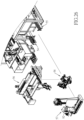
Fig. 1 is a perspective view of a cell passaging device in accordance with the present invention; -
Fig. 2 is another perspective view of the cell passaging device inFig. 1 , showing an internal structure of the cell passaging device; -
Fig. 3 is a top view of the internal structure of the cell passaging device inFig. 2 ; -
Fig. 4 is a simplified schematic top view of the internal structure of the cell passaging device inFig. 3 ; -
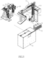
Fig. 5 is an exploded perspective view of a container-handling device and a primary container-moving device of the cell passaging device inFig. 1 ; -
Fig. 6 is a perspective view of the container-handling device of the cell passaging device inFig. 1 ; -
Fig. 7 is an enlarged exploded perspective view of the container-handling device of the cell passaging device inFig. 6 ; -
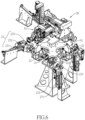
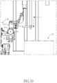
Figs. 8 to 10 are enlarged side views of the cell passaging device inFig. 1 , showing a first multi-axis transfer mechanism of the primary container-moving device moving a cell culture container to a container-handling device; -
Fig. 11 is another enlarged side view of the cell passaging device inFig. 1 , showing a cap mechanism moving down and gripping a cap of a cell culture container; -
Fig. 12 is another enlarged side view of the cell passaging device inFig. 1 , showing an injection head of a liquid solution injection device aligned with the cell culture container; -
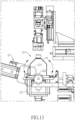
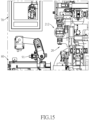
Fig. 13 is another enlarged side view of the cell passaging device inFig. 1 , showing the cell culture container being swayed by the container-handling device; -
Figs. 14 to 16 are enlarged schematic top views of the cell passaging device inFig. 1 , showing an auxiliary container-moving device moving the cell culture container in a container output position, to a centrifuge, or to an optical inspection device; -
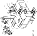
Fig. 17 is an enlarged exploded perspective view of the cell passaging device inFig. 1 , showing a liquid equal-splitting device; -
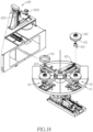
Fig. 18 is an exploded perspective view of the liquid equal-splitting device of the cell passaging deviceFig. 17 ; -
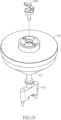
Fig. 19 is an exploded perspective view of a gravitational liquid-splitting device of the cell passaging deviceFig. 18 ; -
Fig. 20 is a sectional view of the gravitational liquid-splitting device of the cell passaging deviceFig. 19 , showing a first ferromagnetic part closing a bottom opening of a funnel; -
Figs. 21 and22 are enlarged sectional views of the container-handling device of the cell passaging device inFig. 1 , showing the cell culture container being rotated to an emptying angle to transfer contents of the cell culture container to the gravitational liquid-splitting device thereunder; -
Figs. 23 and24 are enlarged side views of the container-handling device of the cell passaging device inFig. 1 , showing a stirring motor moved downward to connect a stirrer; -
Fig. 25 is an enlarged sectional view of the cell passaging device inFig. 1 , showing a dispensing valve opening the bottom opening of the funnel; -
Fig. 26 is another enlarged exploded perspective view of the cell passaging device inFig. 1 ; -
Fig. 27 is another enlarged side view of the cell passaging device inFig. 1 ; and -
Fig. 28 is another enlarged sectional view of the cell passaging device inFig. 1 , showing contents in the gravitational liquid-splitting device being split equally and flowing downward to two centrifuge containers thereunder. - With reference to
Figs. 1 to 4 and28 , the cell passaging device in accordance with the present invention is configured to collect contents (i.e. solution with detached cells) from multiplecell culture containers 91, and then split the collected contents between the twocentrifuge containers 92 for centrifugation. Cells in solution separated by centrifuge can be used for cell subculture with other cell culture devices. The cell passaging is preferably also configured to transfer the separated cells from solution to cryovials (not shown in figures) for cryopreservation, or to cell solution containers (not shown in figures) for shipments. - The
cell culture containers 91 and thecentrifuge containers 92 are containers in the same shape preferably. In the preferred embodiment, theculture containers 91 are configured to be put in a centrifuge directly for centrifugation, and therefore thecentrifuge containers 92 can be two of thecell culture containers 91 as well. - The cell passaging device has a
base 10, a container-handlingdevice 20, and a liquid equal-splittingdevice 40. In the preferred embodiment, the cell passaging device further has a liquidsolution injection device 30, a primary container-movingdevice 50, an auxiliary container-movingdevice 60, acentrifuge 70, and anoptical inspection device 80. - With reference to
Figs. 4 to 7 , the container-handlingdevice 20 is mounted on thebase 10 and has a container-positioning table 21,multiple container holders 22, and multiple container-drivingassemblies 23. - The container-positioning table 21 is rotatably mounted on the
base 10, and is preferably a conventional rotary indexing table. The container-positioning table 21 rotates 90 degrees each time, thereby defining four stationary positions that are fixed in space. The four stationary positions are respectively a container-receivingposition 211, acontainer output position 212, afirst injection position 213, and asecond injection position 214, wherein thesecond injection position 214 and thecontainer output position 212 are oppositely disposed on the container-handlingdevice 20. - In the terminology of this technical field, the container-positioning table 21 has four indexed positions: the aforementioned container-receiving
position 211, thecontainer output position 212, thefirst injection position 213, and thesecond injection position 214 are the four indexed positions of the container-positioning table 21. - A number of the
container holders 22 is preferably four; the fourcontainer holders 22 are disposed around the container-positioning table 21 at angular intervals of 90 degrees. The container-positioning table 21 is configured to move eachcontainer holder 22 cyclically among the container-receivingposition 211, thecontainer output position 212, thefirst injection position 213, and thesecond injection position 214. - The container-positioning table 21 is not limited to rotary motion. In another preferred embodiment (not shown in figures), the container-positioning table 21 moves the
container holder 22 along a straight line or a bent line to move thecontainer holder 22 among multiple specific positions. Moreover, the container-positioning table 21 is not limited to move eachcontainer holder 22 to four different positions; in a less-automated embodiment of the cell passaging device, that is, the container-positioning table 21 only moves thecontainer holder 22 to thefirst injection position 213. - With reference to
Figs. 7 ,21 and22 , eachcontainer holder 22 is configured to accommodate one of thecell culture containers 91 or one of thecentrifuge containers 92. Each of thecontainer holders 22 is pivotally mounted on the container-positioning table 21, and is pivotable to an emptying angle (as shown inFig. 22 ) to empty contents in theculture container 91 or thecentrifuge container 92. To be precise, eachcontainer holder 22 is mounted on the container-positioning table 21 via ashaft 221 and is pivotable around the shaft 221.Theshaft 221 is preferably horizontal. - With reference to
Figs. 6 ,7 , and13 , a number of the container-drivingassemblies 23 equals the number of thecontainer holders 22. Each of the container-drivingassemblies 23 controls an angle of a respective one of thecontainer holders 22 and is configured to rotate the respective one of thecontainer holders 22 to the emptying angle or to sway the respective one of thecontainer holders 22. - In the preferred embodiment, each container-driving
assembly 23 is mounted on the base and has alinear module 231, amotor 232, and one ormultiple driving wheels 233. Thelinear module 231 is mounted on thebase 10. Themotor 232 and the drivingwheels 233 are mounted on a slider of thelinear module 231. - A position of said slider is controllable and the slider is configured to move toward the
container holder 22 to make the drivingwheels 233 abut against a drivenwheel 222. The drivenwheel 222 is connected to theshaft 221 such that themotor 232 can control the angle of thecorresponding container holder 22 via the drivingwheels 233 and the drivenwheel 222. By mounting the container-drivingassembly 23 on the base 10 instead of the container-positioning table 21, makes cabling of thelinear module 231 andmotor 232 more simplified. - With reference to
Figs 3 ,4 , and12 , the liquidsolution injection device 30 is mounted on thebase 10 and has multiple injection heads 31. Each of the injection heads 31 is connected to a container with a kind of liquid solution and is movable to a position above thesecond injection position 214 to inject the liquid solution in a connected container into thecell culture container 91 located in thecontainer holder 22 at thesecond injection position 214. The liquidsolution injection device 30 is preferably disposed on a side, which is toward thesecond injection position 214, of the container-handlingdevice 20. - In the preferred embodiment, the liquid
solution injection device 30 is a turret. The injection heads 31 are disposed around a center axis of the turret and the turret is configured to rotate a specifiedinjection head 31 to the position above thesecond injection position 214 for liquid solution injection. The liquid solutions connected to theinjection head 31 include kinds of liquid reagents which can make adherent cells detach from a surface of thecell culture container 91, and also include balance reagent which can neutralize the effectiveness of the detaching reagent. - With reference to
Figs. 3 ,4 ,17 and18 , the liquid equal-splittingdevice 40 is disposed on a side of the container-handlingdevice 20; the liquid equal-splittingdevice 40 has a funnel-positioning table 41 and at least one gravitational liquid-splittingdevice 42. The funnel-positioning table 41 is rotatably mounted on thebase 10, and is preferably a conventional rotary indexing table. - The funnel-positioning table 41 is disposed lower in height than the container-positioning table 21, but disposed higher in height than the position of two
centrifuge containers 92. One indexed position of the funnel-positioning table 41 is located under thefirst injection position 213 of the container-positioning table 21, and another indexed position of the funnel-positioning table 41 is located above the position of twocentrifuge containers 92. - With reference to
Figs. 18 to 20 , the number of the gravitational liquid-splittingdevice 42 is preferably four, at least one, and the four gravitational liquid-splittingdevices 42 are disposed around a center axis of the funnel-positioning table 41. Each gravitational liquid-splittingdevice 42 has afunnel 421, a dispensingvalve 422, a liquid-splittingpart 423, and a stirringassembly 425. In the preferred embodiment, each gravitational liquid-splittingdevices 42 further has afunnel cover 424. Thefunnel 421 has an inner space and a bottom opening, and the inner space is connected to the bottom opening. A firstferromagnetic part 4221 of the dispensingvalve 422 is mounted in thefunnel 421 and is configured to close or open the bottom opening of thefunnel 421. Here "closing the bottom opening" means the dispensingvalve 422 prevents liquid in thefunnel 421 from flowing down via the bottom opening, and therefore thefunnel 421dispensing valve 422 does not have to directly cover the bottom opening. - In the preferred embodiment, the inner space of the
funnel 421 forms a channel 4211 (as shown inFig. 20 ) in the bottom of thefunnel 421. Thechannel 4211 extends upward and downward, and a lower end of thechannel 4211 forms the bottom opening of thefunnel 421. The firstferromagnetic part 4221 of the dispensingvalve 422 is disposed in thechannel 4211 and is configured to be controlled to close or open thechannel 4211, thereby closing or opening the bottom opening of thefunnel 421. - With reference to
Figs. 20 to 23 andFig. 25 , the dispensingvalve 422 has the firstferromagnetic part 4221, avalve actuator 4222, and a secondferromagnetic part 4223. The firstferromagnetic part 4221 is movably disposed in thechannel 4211 of thefunnel 421 and driven by a weight of the firstferromagnetic part 4221 to move toward the bottom opening of thefunnel 421 to close the bottom opening (as shown inFig. 20 ). The firstferromagnetic part 4221 is preferably a ball with a metal core. - The
valve actuator 4222 is disposed outside of thefunnel 421 and has a movingend 4222A which is controllable and configured to move toward the firstferromagnetic part 4221 to an open position (as shown inFig. 25 ). To be precise, thevalve actuator 4222 is a pneumatic cylinder. Thevalve actuator 4222 is mounted on thebase 10 and can be controlled by pressurized air to make a slider of thevalve actuator 4222 move toward the firstferromagnetic part 4221. - The second
ferromagnetic part 4223 is mounted on a movingend 4222A of thevalve actuator 4222. The secondferromagnetic part 4223 and the firstferromagnetic part 4221 magnetically attract or repel each other. When the movingend 4222A of thevalve actuator 4222 is at the open position, the firstferromagnetic part 4221 is driven by the secondferromagnetic part 4223 to open the bottom opening of the funnel. - In the preferred embodiment, the second
ferromagnetic part 4223 is a permanent magnet. When the movingend 4222A of thevalve actuator 4222 is at the open position, the firstferromagnetic part 4221 is magnetically attracted by the secondferromagnetic part 4223 and opens thechannel 4211. In another preferred embodiment (not shown in figures), the firstferromagnetic part 4221 and the secondferromagnetic part 4223 are permanent magnets which magnetically attract or repel each other, or the secondferromagnetic part 4223 is a coil which generates magnetic field when powered-on. - With reference to
Figs. 18 to 20 , the liquid-splittingpart 423 is connected to the bottom of thefunnel 421. The liquid-splittingpart 423 has aninput channel 4231, twooutput channels 4232, and twoauxiliary channels 4233 formed in the liquid-splittingpart 423, but the auxiliary channels can be omitted. - The
input channel 4231 extends upward and downward; an upper end of theinput channel 4231 forms an input opening on a top of the liquid-splittingpart 423 and connected to the bottom opening of the funnel. Each of theoutput channels 4232 has a first end and a second end; the first end is connected to a lower end of theinput channel 4231; the second end extends inclinedly downward and connected to an exterior of the liquid-splitting part. - Liquid entering the
input channel 4231 is split equally between the twooutput channels 4232 by gravity and shapes of theoutput channels 4232. In the preferred embodiment, eachoutput channel 4232 is linear, and its lower end is connected to the exterior of the liquid-splitting part via a vertical channel. - Each
auxiliary channel 4233 has a third end and a fourth end; the third end is connected to one of the twooutput channels 4232; the fourth end extends inclinedly upward and is connected to the exterior of the liquid-splitting part. To be specific, eachauxiliary channel 4233 extends along a same straight line with a respective one of theoutput channels 4232. - Function of the
auxiliary channels 4233 is to balance pressure in the twooutput channels 4232, thereby stabilizing flow speed in the twooutput channels 4232. Therefore, theauxiliary channels 4233 further ensure the liquid entering theinput channel 4231 is split equally between the twooutput channels 4232. Moreover, eachauxiliary channel 4233 is in line with a respective one of theoutput channels 4232 for ease of cleaning. In another preferred embodiment, there is only oneauxiliary channel 4233, and the third end of theauxiliary channel 4233 is connected to both of the twooutput channels 4232. - With reference to
Figs. 18 ,20 ,23 , and24 , thefunnel cover 424 detachably covers an upper opening of thefunnel 421. The stirringassembly 425 has alinear module 4251, a stirringmotor 4252, and astirrer 4253. Thelinear module 4251 is mounted on thebase 10 and can be controlled to move aslider 4251A of thelinear module 4251. The stirringmotor 4252 is mounted on theslider 4251A of thelinear module 4251. Thestirrer 4253 is rotatably mounted through thefunnel cover 424 and is configured to stir liquid in thefunnel 421. - When the
funnel cover 424 covers thefunnel 421, thelinear module 4251 is configured to move the stirringmotor 4252 toward the stirrer 4253 (as shown inFig. 24 ) such that an output axle of the stirringmotor 4252 is connected to an upper end of thestirrer 4253, thereby allowing the stirringmotor 4252 to rotate thestirrer 4253. Structure of the stirringassembly 425 is not limited by the abovementioned as long as there is astirrer 4253 configured to stir liquid in thefunnel 421. - With reference to
Figs. 3 ,4 ,18 , and20 , rotation of the funnel-positioning table 41 is configured to move each of the gravitational liquid-splittingdevices 42 from a position under thefirst injection position 213 to a position above the position of twocentrifuge containers 92 such that liquid in thefunnel 421 of each gravitational liquid-splittingdevice 42 flows into the twocentrifuge containers 92 via the twooutput channels 4232 respectively. - In the preferred embodiment, the funnel-positioning table 41 is both rotatable on a horizontal plane and linearly movable toward or away from the container-handling
device 20. The funnel-positioning table 41 moves each gravitational liquid-splittingdevice 42 to the position above the twocentrifuge containers 92 by a combination of said rotation and linear motion. - Operation mode of the funnel-positioning table 41 is not limited to rotation. In another preferred embodiment, the funnel-positioning table 41 moves the gravitational liquid-splitting
devices 42 along a straight line or a bent line to move the gravitational liquid-splittingdevices 42 among multiple specific positions. - With reference to
Figs. 2 to 4 andFig. 28 , the primary container-movingdevice 50 is configured to move each of the twocentrifuge containers 92 from the position under the gravitational liquid-splittingdevice 42 to thecontainer holder 22 at the container-receivingposition 211. - Additionally, the primary container-moving
device 50 is also configured to move thecell culture container 91 in thecontainer holder 22 at the container-receivingposition 211 to the position under the gravitational liquid-splittingdevices 42 such that liquid in thefunnel 421 of the corresponding gravitational liquid-splittingdevice 42 flows into thecell culture container 91. Therefore, the primary container-movingdevice 50 allows the present invention to recycle two of thecell culture containers 91 so that they can be used again as the twocentrifuge containers 92. - In the preferred embodiment, the primary container-moving
device 50 has a firstmulti-axis transfer mechanism 51, acontainer rack 52, afirst conveyer 53, asecond conveyer 54, athird conveyer 55, a secondmulti-axis transfer mechanism 56, and a bottling andtransferring mechanism 57.
With reference toFig. 5 andFigs. 8 to 10 , the firstmulti-axis transfer mechanism 51 is preferably a three-axis transfer mechanism which includes threelinear modules 511. One of thelinear modules 511 that extends vertically has agripper 512 mounted on a lower end of saidlinear module 511. Thegripper 512 is configured to grip one of the containers (e.g., thecell culture container 91 or the centrifuge container 92) accommodated in thecontainer holder 22 at the container-receivingposition 211, thecontainer rack 52, or thefirst conveyer 53. Thegripper 512 is also configured to put the gripped container in any one of the said three components. To be more precise, thegripper 512 is configured to rotate 90 degrees along a horizontal axis to change an angle of the gripped container. - The
container rack 52 is configured to accommodate twelve containers to improve operational efficiency. Thefirst conveyer 53 includes a translating mechanism and an elevating mechanism such that thefirst conveyer 53 moves containers from a bottom to a top of thefirst conveyer 53 where the firstmulti-axis transfer mechanism 51 can grip the container or put several new containers in thecontainer rack 52 one by one. - The
second conveyer 54 and thethird conveyer 55 are linear belt conveyors. One end of each conveyor is mounted in a bottom of thefirst conveyer 53, and another end of each conveyor extends to the secondmulti-axis transfer mechanism 56. - The second
multi-axis transfer mechanism 56 is preferably a three-axis transfer mechanism which is configured to move containers among thesecond conveyer 54, thethird conveyer 55, and the bottling andtransferring mechanism 57. - With reference to
Figs. 26 to 28 , the bottling andtransferring mechanism 57 is configured to grip thedouble centrifuge containers 92, double thecell culture containers 91, double cryovials (not shown in figures), double cell solution containers (not shown in figures), or other types of containers. The bottling andtransferring mechanism 57 is configured to align the two gripped containers with the twooutput channels 4232 of one of the gravitational liquid-splittingdevices 42 such that the liquid in said gravitational liquid-splittingdevice 42 can be transferred to the two gripped containers. After transferring the liquid, the bottling andtransferring mechanism 57 moves the two gripped containers away from the position under the container-positioning table 21 for the secondmulti-axis transfer mechanism 56 to grip for the further operation. - In the preferred embodiment, a cell solution
container cap mechanism 58 is disposed under the secondmulti-axis transfer mechanism 56. The cell solutioncontainer cap mechanism 58 is configured to handle caps of the cell solution containers in collaboration with the secondmulti-axis transfer mechanism 56. - With reference to
Figs. 2 to 4 , the auxiliary container-movingdevice 60, thecentrifuge 70, and theoptical inspection device 80 are disposed on a same side of the container-handlingdevice 20 as where thecontainer output position 212 is. Thecentrifuge 70 and theoptical inspection device 80 are standardized conventional equipment. Theoptical inspection device 80 is configured to measure a number of cells in theculture container 91 in order to determine whether a total number of the cells collected in theculture container 91 is satisfactory for the further cell passaging process. To be more specific, theoptical inspection device 80 is configured to calculate automatically the number of detached cells in thecell culture containers 91 by a specific AI algorithm. - With reference to
Figs. 14 to 16 , the auxiliary container-movingdevice 60 is configured to move thecentrifuge container 92 or thecell culture container 91 in thecontainer holder 22 at thecontainer output position 212 into thecentrifuge 70, and also configured to move thecentrifuge container 92 or thecell culture container 91 in thecentrifuge 70 back into thecontainer holder 22 at thecontainer output position 212. - Additionally, the auxiliary container-moving
device 60 is configured to move thecentrifuge container 92 or thecell culture container 91 in thecontainer holder 22 at thecontainer output position 212 into theoptical inspection device 80, and also configured to move thecentrifuge container 92 or thecell culture container 91 in theoptical inspection device 80 back into thecontainer holder 22 at thecontainer output position 212. The auxiliary container-movingdevice 60 is preferably a robotic arm. - The cell passaging method in accordance with the present invention is preferably performed using the abovementioned cell passaging device. The cell passaging device is configured to automatically perform various cell passaging methods for cell subculture process. One of the cell passaging methods for subculture of adherent cells, which is in accordance with the present invention, is explained below.
- With reference to
Figs. 3 to 5 , multiplecell culture containers 91 already in the stationary phase are transmitted to thefirst conveyer 53 of the primary container-movingdevice 50 by an external transfer mechanism. - With reference to
Figs. 8 to 10 , then, the firstmulti-axis transfer mechanism 51 grips thecell culture containers 91 in thefirst conveyer 53 and dispenses thecell culture containers 91 into thecontainer holder 22 at the container-receivingposition 211. Thegripper 512 of the firstmulti-axis transfer mechanism 51 rotates the grippedcell culture container 91 from a horizontal posture to a vertical posture (as shown inFigs. 8 and9 ) before putting the grippedcell culture container 91 into thecontainer holder 22 for ease of subsequent operation. - With reference to
Figs. 4 and11 , then, thecell culture container 91 is moved from the container-receivingposition 211 to thesecond injection position 214. Acap mechanism 81 moves down to grip a cap of thecell culture container 91. - With reference to
Fig. 12 , then, acap mechanism 81 loosens the cap of thecell culture container 91 and moves the cap aside, and the container-drivingassembly 23 rotates thecontainer holder 22 to empty the content (ex. medium) of thecell culture container 91. Then, theinjection head 31 of the liquidsolution injection device 30 moves to the position above thesecond injection position 214 and injects the detaching reagent (ex. Trypsin) into thecell culture container 91, wherein the detaching reagent is functioned to make the adherent cells detach from the surface of thecell culture container 91. - With reference to
Figs. 4 and13 , then, thecap mechanism 81 puts the cap back onto thecell culture container 91 and tightens the cap, and theculture container 91 is moved to thefirst injection position 213. The container-drivingassembly 23 sways theculture container 91 at thefirst injection position 213 to make cells detached from the surface of thecell culture container 91. - With reference to
Figs. 14 and15 , then, thecell culture container 91 is moved to thecontainer output position 212, and then the auxiliary container-movingdevice 60 grips thecell culture container 91 and dispenses theculture container 91 into theoptical inspection device 80 to calculate automatically the number of cells in thecell culture container 91 by using a specific AI algorithm. - When the process of cell counting in the
optical inspection device 80 has finished, theculture cell container 91 is moved back to thecontainer output position 212, and subsequently moved to thesecond injection position 214. At thesecond injection position 214, another one of the injection heads 31 of the liquidsolution injection device 30 injects balance reagent into thecell culture container 91 to neutralize the effectiveness of detaching reagent. - With reference to
Figs. 4 ,21 , and22 , then, theculture cell container 91 is moved to thefirst injection position 213, and the container-drivingassembly 23 rotates thecontainer holder 22 to pour contents (e.g., solution with detached cells) in thecell culture container 91 into thefunnel 421 of the gravitational liquid-splittingdevice 42. Thefunnel cover 424 on top of thefunnel 421 has been removed before this step. Then, the above steps are performed again for the rest of thecell culture containers 91 until the solutions with detached cells from allculture containers 91 are collected in thefunnel 421. - Among the
cell culture containers 91, the first twocell culture containers 91 are moved to the position under one of the gravitational liquid-splittingdevices 42 after their solutions with detached cells are poured into thefunnel 421 such that the first twocell culture containers 91 serve as the twocentrifuge containers 92. - With reference to
Figs. 23 and24 , after the solutions with detached cells from allcell culture containers 91 are collected in thefunnel 421, the funnel-positioning table 41 moves the gravitational liquid-splittingdevice 42 clockwise to the position above the twocentrifuge containers 92, and meanwhile theslider 4251A of the stirringassembly 425 moves down to connect the stirringmotor 4252 to the upper end of thestirrer 4253. The stirringmotor 4252 drives thestirrer 4253 to keep stirring the solution with detached cells in thefunnel 421. - With reference to
Figs. 25 and28 , then, thevalve actuator 4222 of the dispensingvalve 422 moves the secondferromagnetic part 4223 toward the firstferromagnetic part 4221 to the open position to move the firstferromagnetic part 4221 such that the solution with detached cells in thefunnel 421 is split equally between the twocentrifuge containers 92. - With reference to
Fig. 4 , finally, the twocentrifuge containers 92 are moved to the container-handlingdevice 20 by the primary container-movingdevice 50, and then moved into thecentrifuge 70 by the auxiliary container-movingdevice 60 to perform centrifugation. After the centrifugation, the twocentrifuge containers 92 are ready for subsequent cell passaging operations. - The cell passaging method in accordance with the present invention is not limited to aforementioned as long as contents in the
cell culture containers 91 are split equally between the twocentrifuge containers 92 by using the gravitational liquid-splittingdevice 42, and then the twocentrifuge containers 92 are disposed oppositely in thecentrifuge 70 to perform centrifugation to separate the cells from the solution. - In addition to performing the abovementioned cell passaging method, the cell passaging device is also configured to automatically perform various processes related to cell culture processing, such as primary specimen cells extraction process, cell culture container medium exchange process, cell culture container optical inspection process, and some of the cell cryopreservation processes such as cryovial dispensing, partial cell thawing process, and cell solution bottling for shipping process.
- In summary, liquid (solution with detached cells) in the
funnel 421 automatically flows downward into thecentrifuge containers 92 due to gravity because the liquid-splittingpart 423 of the gravitational liquid-splittingdevice 42 is disposed under thefunnel 421, theinput channel 4231 extends upward and downward, and meanwhile theoutput channels 4232 extend inclinedly downward; therefore, no liquid residue is left in thefunnel 421, theinput channel 4231, and theoutput channel 4232. - As a result, the present invention prevents loss of cells during transferring operation, avoids damage to the cells under pressurization by using pump, and effectively automates the process of collecting solution with detached cells together and then split the collected solution with detached cells equally between the two
centrifuge containers 92, thereby improving efficiency of cell passaging and reducing cost of cell passaging. - Moreover, with the
stirrer 4253 of the gravitational liquid-splittingdevice 42 continuously stirring the solution with detached cells in the funnel, 421, the present invention prevents cells from clustering together or adhering to surfaces of thefunnel 421 or channels, thereby keeping flow rates in the twooutput channels 4232 remain equal and ensuring the solution with detached cells is split equally between the twocentrifuge containers 92. - Finally, the cell passaging device replaces traditional manual shaking operation by automatically swaying the
cell culture container 91, transferring the solution with detached cells into the gravitational liquid-splittingdevice 42, and splitting the solution with detached cells equally between the twocentrifuge containers 92, thereby reducing labor-intensity for the cell passaging operation. As a result, the present invention has advantages such as high efficiency, stable quality, and reducing risk of contamination in cell passaging processes.
Claims (11)
- A gravitational liquid-splitting device (42) characterized in that the gravitational liquid-splitting device (42) comprises:a funnel (421) having an inner space and a bottom opening connected to the inner space;a dispensing valve (422) mounted to the funnel (421) and configured to close or open the bottom opening of the funnel (421);a liquid-splitting part (423) connected to a bottom of the funnel (421) and having:an input channel (4231) formed in the liquid-splitting part (423) and extending upward and downward; an upper end of the input channel (4231) forming an input opening on a top of the liquid-splitting part (423) and connected to the bottom opening of the funnel (421); andtwo output channels (4232) formed in the liquid-splitting part (423); each of the output channels (4232) having a first end and a second end; the first end connected to a lower end of the input channel (4231); the second end extending inclinedly downward and connected to an exterior of the liquid-splitting part (423); anda stirring assembly (425) havinga funnel (421) cover detachably covering an upper opening of the funnel (421); anda stirrer (4253) connected to the funnel (421) cover and configured to stir liquid in the funnel (421).
- The gravitational liquid-splitting device (42) as claimed in claim 1, wherein the liquid-splitting part (423) has at least one auxiliary channel (4233) formed in the liquid-splitting part (423) and having:a third end connected to one of the two output channels (4232); anda fourth end extending inclinedly upward and connected to the exterior of the liquid-splitting part (423) .
- The gravitational liquid-splitting device (42) as claimed in claim 2, wherein the at least one auxiliary channel (4233) includes two auxiliary channels (4233); each of the two auxiliary channels (4233) is connected to a respective one of the two output channels (4232) and extends along a same straight line with said output channel (4232).
- The gravitational liquid-splitting device (42) as claimed in any one of claims 1 to 3, wherein the dispensing valve (422) has:a first ferromagnetic part (4221) movably disposed in the inner space of the funnel (421) and driven by a weight of the first ferromagnetic part (4221) to move toward the bottom opening of the funnel (421) to close the bottom opening;a valve actuator (4222) disposed outside of the funnel (421); a moving end (4222A) of the valve actuator (4222) being movable toward the first ferromagnetic part (4221) to an open position;a second ferromagnetic part (4223) mounted to the moving end (4222A) of the valve actuator (4222); the second ferromagnetic part (4223) and the first ferromagnetic part (4221) magnetically attracting or repelling each other;wherein, when the moving end (4222A) of the valve actuator (4222) is at the open position, the first ferromagnetic part (4221) is driven by the second ferromagnetic part (4223) to open the bottom opening of the funnel (421).
- A cell passaging device, configured to concentrate contents collected from multiple cell culture containers (91) into two centrifuge containers (92); the cell passaging device characterized in that the cell passaging device comprises:a base (10);a container-handling device (20) mounted on the base (10) and having:a container-positioning table (21) rotatably or movably mounted on the base (10);multiple container holders (22) pivotally mounted on the container-positioning table (21); each of the container holders (22) configured to accommodate one of the cell culture containers (91) or one of the centrifuge containers (92), and being pivotable to an emptying angle to empty contents in the cell culture container (91) or the centrifuge container (92); andmultiple container-driving assemblies (23); each of the container-driving assemblies (23) controlling an angle of a respective one of the container holders (22) and configured to rotate the respective one of the container holders (22) to the emptying angle or to sway the respective one of the container holders (22);wherein, the container-positioning table (21) is configured to move each of the container holders (22) to a first injection position (213); anda liquid equal-splitting device (40) disposed on a side of the container-handling device (20); the liquid equal-splitting device (40) having:a funnel-positioning table (41) rotatably or movably mounted on the base (10); andat least one said gravitational liquid-splitting device (42) as claimed in any one of claims 1 to 4 mounted on the funnel-positioning table (41);wherein, the funnel-positioning table (41) is configured to move the at least one gravitational liquid-splitting device (42) from a position under the first injection position (213) to a position above the two centrifuge containers (92) such that the liquid in the funnel (421) of the at least one gravitational liquid-splitting device (42) flows into the two centrifuge containers (92) via the two output channels (4232) respectively.
- The cell passaging device as claimed in claim 5, wherein:the container-positioning table (21) is configured to move each of the container holders (22) to a second injection position (214); andthe cell passaging device has a liquid solution injection device (30); the liquid solution injection device (30) is mounted on the base (10) and has multiple injection heads (31); each of the injection heads (31) is connected to a container with a kind of liquid solution and is movable to a position above the second injection position (214) to inject the liquid solution in the container into the cell culture container (91) located in the container holder (22) in the second injection position (214).
- The cell passaging device as claimed in claim 5, wherein:the container-positioning table (21) of the container-handling device (20) is configured to move each of the container holders (22) to a container-receiving position (211) or a container output position (212);the cell passaging device has:a primary container-moving device (50) configured to move each of the two centrifuge containers (92) from the position under the at least one gravitational liquid-splitting device (42) to the container holder (22) at the container-receiving position (211);a centrifuge disposed on a side of the container-handling device (20); andan auxiliary container-moving device configured to move the centrifuge container (92) in the container holder (22) at the container output position (212) into the centrifuge, and configured to move the centrifuge container (92) in the centrifuge back into the container holder (22) at the container output position (212).
- The cell passaging device as claimed in claim 5, wherein:the container-positioning table (21) of the container-handling device (20) is configured to move each of the container holders (22) to a container-receiving position (211) or a container output position (212);the cell passaging device has:an optical inspection device (80) disposed on a side of the container-handling device (20) and configured to calculate the number of detached cells in the cell culture containers (91); andan auxiliary container-moving device (60) configured to move the cell culture container (91) in the container holder (22) at the container output position (212) into the optical inspection device (80), and configured to move the cell culture container (91) in the optical inspection device (80) back into the container holder (22) at the container output position (212).
- The cell passaging device as claimed in claim 7, wherein:the container-positioning table (21) of the container-handling device (20) is rotatably mounted on the base (10) and configured to move each of the container holders (22) to circulate between the container-receiving position (211), the container output position (212), the first injection position (213), and a second injection position (214);the cell passaging device has:a liquid solution injection device (30) mounted on the base (10) and having multiple injection heads (31); each of the injection heads (31) connected to a container with a kind of liquid solution and being movable to a position above the second injection position (214) to inject the liquid solution in the container into the cell culture container (91) located in the container holder (22) at the second injection position (214); andan optical inspection device (80) disposed on a side of the container-handling device (20) and configured to calculate the number of detached cells in the cell culture containers (91); andthe auxiliary container-moving device (60) is configured to move the cell culture container (91) in the container holder (22) at the container output position (212) into the optical inspection device (80), and configured to move the cell culture container (91) in the optical inspection device (80) back into the container holder (22) at the container output position (212);wherein, the second injection position (214) and the container output position (212) are oppositely disposed on the container-handling device (20); the centrifuge, the auxiliary container-moving device (60), and the optical inspection device (80) are disposed on a side, which is toward the container output position (212), of the container-handling device (20); the liquid solution injection device (30) is disposed on a side, which is toward the second injection position (214), of the container-handling device (20).
- The cell passaging device as claimed in claim 5, wherein:the container-positioning table (21) of the container-handling device (20) is configured to move each of the container holders (22) to a container-receiving position (211) or a container output position (212); andthe cell passaging device has a primary container-moving device (50); the primary container-moving device (50) is configured to move the cell culture container (91) in the container holder (22) at the container-receiving position (211) to the position under the at least one gravitational liquid-splitting device (42) such that the liquid in the funnel (421) of the at least one gravitational liquid-splitting device (42) flows into the cell culture container (91).
- A cell passaging method for concentrating contents collected from multiple cell culture containers (91) into two centrifuge containers (92); the cell passaging method characterized in that the cell passaging method comprises steps of: using the gravitational liquid-splitting device (42) as claimed in any one of claims 1 to 4 to split contents in the cell culture containers (91) equally between the two centrifuge containers (92), then disposing the two centrifuge containers (92) oppositely in a centrifuge and using the centrifuge to perform centrifugation.
Priority Applications (1)
| Application Number | Priority Date | Filing Date | Title |
|---|---|---|---|
| EP23154610.2A EP4410950B1 (en) | 2023-02-02 | 2023-02-02 | Gravitational liquid-splitting device, cell passaging device with the same, and cell passaging method |
Applications Claiming Priority (1)
| Application Number | Priority Date | Filing Date | Title |
|---|---|---|---|
| EP23154610.2A EP4410950B1 (en) | 2023-02-02 | 2023-02-02 | Gravitational liquid-splitting device, cell passaging device with the same, and cell passaging method |
Publications (3)
| Publication Number | Publication Date |
|---|---|
| EP4410950A1 EP4410950A1 (en) | 2024-08-07 |
| EP4410950B1 true EP4410950B1 (en) | 2025-05-28 |
| EP4410950C0 EP4410950C0 (en) | 2025-05-28 |
Family
ID=85172586
Family Applications (1)
| Application Number | Title | Priority Date | Filing Date |
|---|---|---|---|
| EP23154610.2A Active EP4410950B1 (en) | 2023-02-02 | 2023-02-02 | Gravitational liquid-splitting device, cell passaging device with the same, and cell passaging method |
Country Status (1)
| Country | Link |
|---|---|
| EP (1) | EP4410950B1 (en) |
Family Cites Families (4)
| Publication number | Priority date | Publication date | Assignee | Title |
|---|---|---|---|---|
| US20060257999A1 (en) * | 2005-03-22 | 2006-11-16 | Chang Jim Y | Compound profiling devices, systems, and related methods |
| CN107109336A (en) * | 2014-11-06 | 2017-08-29 | 奥林巴斯株式会社 | Cell culture system and cell culture container |
| KR102373674B1 (en) * | 2016-06-20 | 2022-03-11 | 제네시스 테크놀로지스 리미티드 | Automated Cell Handling Systems and Methods |
| MX2021015125A (en) * | 2019-06-07 | 2022-04-06 | Juno Therapeutics Inc | AUTOMATED CULTURE OF T CELLS. |
-
2023
- 2023-02-02 EP EP23154610.2A patent/EP4410950B1/en active Active
Also Published As
| Publication number | Publication date |
|---|---|
| EP4410950A1 (en) | 2024-08-07 |
| EP4410950C0 (en) | 2025-05-28 |
Similar Documents
| Publication | Publication Date | Title |
|---|---|---|
| CN111207545B (en) | Low-temperature access device and low-temperature access method | |
| JP2001194372A (en) | Container transfer processing system | |
| CN119044519B (en) | Sample pretreatment system | |
| CN216838008U (en) | Cell preparation system | |
| WO2022016475A1 (en) | Sample pre-treatment system | |
| CN118207073A (en) | Microorganism inspection processing system | |
| CN112725168A (en) | Automatic processing system for microbial samples | |
| JP7804379B2 (en) | Fully automatic photoresist coating and baking equipment for scientific research | |
| JP2008533989A (en) | Device, system and related methods for profile analysis of compounds | |
| US12606791B2 (en) | Gravitational liquid-splitting device, cell passaging device with the same, and cell passaging method | |
| EP4410950A1 (en) | Gravitational liquid-splitting device, cell passaging device with the same, and cell passaging method | |
| CN115494803A (en) | Full-flow integrated medicine research and development workstation | |
| CN116087484A (en) | Compact high-efficiency magnetic particle immunity analyzer | |
| CN216639513U (en) | GMP (good manufacturing practice) compliance high-flux intelligent biological medicine production system | |
| CN119709388A (en) | Intelligent microorganism detection pretreatment workstation | |
| CN218910374U (en) | Small-size high-flux plasmid extracts automation workstation | |
| JP7496009B1 (en) | Gravity-type dispensing device, cell subculture device equipped with the same, and cell subculture method using the cell subculture device | |
| CN118056134A (en) | Systems for macromolecular extraction | |
| TW202424177A (en) | Gravity dispensing device, cell subculture processor equipped with the gravity dispensing device, and cell subculture processing method preventing cell aggregation and enhancing automation in cell subculture process by using a gravity dispensing device with a funnel, dispensing valve, diverter, and stirring rod | |
| CN113406341A (en) | Full-automatic specimen pretreatment system | |
| CN118146922A (en) | Gravity dispensing device, cell subculture processing machine with the same, and cell subculture processing method | |
| WO2022096184A1 (en) | Manipulating device for a robot, robot having a manipulating device for a receptacle treatment machine, receptacle treatment machine having a robot and quality control method | |
| US20230135251A1 (en) | Cell and medicament dispensing device for drug screening and method thereof | |
| CN119490907B (en) | Liquid preparation system | |
| TWI912199B (en) | Automated cell culture harvesting system |
Legal Events
| Date | Code | Title | Description |
|---|---|---|---|
| PUAI | Public reference made under article 153(3) epc to a published international application that has entered the european phase |
Free format text: ORIGINAL CODE: 0009012 |
|
| STAA | Information on the status of an ep patent application or granted ep patent |
Free format text: STATUS: REQUEST FOR EXAMINATION WAS MADE |
|
| 17P | Request for examination filed |
Effective date: 20230926 |
|
| AK | Designated contracting states |
Kind code of ref document: A1 Designated state(s): AL AT BE BG CH CY CZ DE DK EE ES FI FR GB GR HR HU IE IS IT LI LT LU LV MC ME MK MT NL NO PL PT RO RS SE SI SK SM TR |
|
| GRAP | Despatch of communication of intention to grant a patent |
Free format text: ORIGINAL CODE: EPIDOSNIGR1 |
|
| STAA | Information on the status of an ep patent application or granted ep patent |
Free format text: STATUS: GRANT OF PATENT IS INTENDED |
|
| RIC1 | Information provided on ipc code assigned before grant |
Ipc: C12M 1/36 20060101AFI20240908BHEP |
|
| INTG | Intention to grant announced |
Effective date: 20241015 |
|
| GRAS | Grant fee paid |
Free format text: ORIGINAL CODE: EPIDOSNIGR3 |
|
| GRAA | (expected) grant |
Free format text: ORIGINAL CODE: 0009210 |
|
| STAA | Information on the status of an ep patent application or granted ep patent |
Free format text: STATUS: THE PATENT HAS BEEN GRANTED |
|
| AK | Designated contracting states |
Kind code of ref document: B1 Designated state(s): AL AT BE BG CH CY CZ DE DK EE ES FI FR GB GR HR HU IE IS IT LI LT LU LV MC ME MK MT NL NO PL PT RO RS SE SI SK SM TR |
|
| REG | Reference to a national code |
Ref country code: GB Ref legal event code: FG4D |
|
| REG | Reference to a national code |
Ref country code: CH Ref legal event code: EP |
|
| REG | Reference to a national code |
Ref country code: IE Ref legal event code: FG4D |
|
| U01 | Request for unitary effect filed |
Effective date: 20250603 |
|
| U07 | Unitary effect registered |
Designated state(s): AT BE BG DE DK EE FI FR IT LT LU LV MT NL PT RO SE SI Effective date: 20250611 |
|
| PG25 | Lapsed in a contracting state [announced via postgrant information from national office to epo] |
Ref country code: ES Free format text: LAPSE BECAUSE OF FAILURE TO SUBMIT A TRANSLATION OF THE DESCRIPTION OR TO PAY THE FEE WITHIN THE PRESCRIBED TIME-LIMIT Effective date: 20250528 |
|
| PG25 | Lapsed in a contracting state [announced via postgrant information from national office to epo] |
Ref country code: GR Free format text: LAPSE BECAUSE OF FAILURE TO SUBMIT A TRANSLATION OF THE DESCRIPTION OR TO PAY THE FEE WITHIN THE PRESCRIBED TIME-LIMIT Effective date: 20250829 Ref country code: NO Free format text: LAPSE BECAUSE OF FAILURE TO SUBMIT A TRANSLATION OF THE DESCRIPTION OR TO PAY THE FEE WITHIN THE PRESCRIBED TIME-LIMIT Effective date: 20250828 |
|
| PG25 | Lapsed in a contracting state [announced via postgrant information from national office to epo] |
Ref country code: PL Free format text: LAPSE BECAUSE OF FAILURE TO SUBMIT A TRANSLATION OF THE DESCRIPTION OR TO PAY THE FEE WITHIN THE PRESCRIBED TIME-LIMIT Effective date: 20250528 |
|
| PG25 | Lapsed in a contracting state [announced via postgrant information from national office to epo] |
Ref country code: HR Free format text: LAPSE BECAUSE OF FAILURE TO SUBMIT A TRANSLATION OF THE DESCRIPTION OR TO PAY THE FEE WITHIN THE PRESCRIBED TIME-LIMIT Effective date: 20250528 |
|
| PG25 | Lapsed in a contracting state [announced via postgrant information from national office to epo] |
Ref country code: RS Free format text: LAPSE BECAUSE OF FAILURE TO SUBMIT A TRANSLATION OF THE DESCRIPTION OR TO PAY THE FEE WITHIN THE PRESCRIBED TIME-LIMIT Effective date: 20250828 |
|
| PG25 | Lapsed in a contracting state [announced via postgrant information from national office to epo] |
Ref country code: IS Free format text: LAPSE BECAUSE OF FAILURE TO SUBMIT A TRANSLATION OF THE DESCRIPTION OR TO PAY THE FEE WITHIN THE PRESCRIBED TIME-LIMIT Effective date: 20250928 |
|
| PG25 | Lapsed in a contracting state [announced via postgrant information from national office to epo] |
Ref country code: SM Free format text: LAPSE BECAUSE OF FAILURE TO SUBMIT A TRANSLATION OF THE DESCRIPTION OR TO PAY THE FEE WITHIN THE PRESCRIBED TIME-LIMIT Effective date: 20250528 |
|
| PG25 | Lapsed in a contracting state [announced via postgrant information from national office to epo] |
Ref country code: CZ Free format text: LAPSE BECAUSE OF FAILURE TO SUBMIT A TRANSLATION OF THE DESCRIPTION OR TO PAY THE FEE WITHIN THE PRESCRIBED TIME-LIMIT Effective date: 20250528 |
|
| PG25 | Lapsed in a contracting state [announced via postgrant information from national office to epo] |
Ref country code: SK Free format text: LAPSE BECAUSE OF FAILURE TO SUBMIT A TRANSLATION OF THE DESCRIPTION OR TO PAY THE FEE WITHIN THE PRESCRIBED TIME-LIMIT Effective date: 20250528 |
|
| REG | Reference to a national code |
Ref country code: CH Ref legal event code: U11 Free format text: ST27 STATUS EVENT CODE: U-0-0-U10-U11 (AS PROVIDED BY THE NATIONAL OFFICE) Effective date: 20260301 |
|
| U20 | Renewal fee for the european patent with unitary effect paid |
Year of fee payment: 4 Effective date: 20260225 |
|
| PLBE | No opposition filed within time limit |
Free format text: ORIGINAL CODE: 0009261 |
|
| STAA | Information on the status of an ep patent application or granted ep patent |
Free format text: STATUS: NO OPPOSITION FILED WITHIN TIME LIMIT |
|
| REG | Reference to a national code |
Ref country code: CH Ref legal event code: L10 Free format text: ST27 STATUS EVENT CODE: U-0-0-L10-L00 (AS PROVIDED BY THE NATIONAL OFFICE) Effective date: 20260409 |
|
| PGFP | Annual fee paid to national office [announced via postgrant information from national office to epo] |
Ref country code: CH Payment date: 20260301 Year of fee payment: 4 |
|
| 26N | No opposition filed |
Effective date: 20260303 |