EP4410698A1 - Kit of blanks, and a package - Google Patents
Kit of blanks, and a package Download PDFInfo
- Publication number
- EP4410698A1 EP4410698A1 EP23461509.4A EP23461509A EP4410698A1 EP 4410698 A1 EP4410698 A1 EP 4410698A1 EP 23461509 A EP23461509 A EP 23461509A EP 4410698 A1 EP4410698 A1 EP 4410698A1
- Authority
- EP
- European Patent Office
- Prior art keywords
- panel
- package
- blank
- lid
- side wall
- Prior art date
- Legal status (The legal status is an assumption and is not a legal conclusion. Google has not performed a legal analysis and makes no representation as to the accuracy of the status listed.)
- Granted
Links
Images

Classifications
-
- B—PERFORMING OPERATIONS; TRANSPORTING
- B65—CONVEYING; PACKING; STORING; HANDLING THIN OR FILAMENTARY MATERIAL
- B65D—CONTAINERS FOR STORAGE OR TRANSPORT OF ARTICLES OR MATERIALS, e.g. BAGS, BARRELS, BOTTLES, BOXES, CANS, CARTONS, CRATES, DRUMS, JARS, TANKS, HOPPERS, FORWARDING CONTAINERS; ACCESSORIES, CLOSURES, OR FITTINGS THEREFOR; PACKAGING ELEMENTS; PACKAGES
- B65D5/00—Rigid or semi-rigid containers of polygonal cross-section, e.g. boxes, cartons or trays, formed by folding or erecting one or more blanks made of paper
- B65D5/42—Details of containers or of foldable or erectable container blanks
- B65D5/64—Lids
- B65D5/643—Lids held in closed position by application of separate elements, e.g. clips, straps
-
- B—PERFORMING OPERATIONS; TRANSPORTING
- B65—CONVEYING; PACKING; STORING; HANDLING THIN OR FILAMENTARY MATERIAL
- B65D—CONTAINERS FOR STORAGE OR TRANSPORT OF ARTICLES OR MATERIALS, e.g. BAGS, BARRELS, BOTTLES, BOXES, CANS, CARTONS, CRATES, DRUMS, JARS, TANKS, HOPPERS, FORWARDING CONTAINERS; ACCESSORIES, CLOSURES, OR FITTINGS THEREFOR; PACKAGING ELEMENTS; PACKAGES
- B65D5/00—Rigid or semi-rigid containers of polygonal cross-section, e.g. boxes, cartons or trays, formed by folding or erecting one or more blanks made of paper
- B65D5/42—Details of containers or of foldable or erectable container blanks
- B65D5/64—Lids
- B65D5/66—Hinged lids
- B65D5/6626—Hinged lids formed by folding extensions of a side panel of a container body formed by erecting a "cross-like" blank
- B65D5/6673—Hinged lids formed by folding extensions of a side panel of a container body formed by erecting a "cross-like" blank the lid being held in closed position by application of separate elements, e.g. clips, hooks, cords
-
- B—PERFORMING OPERATIONS; TRANSPORTING
- B65—CONVEYING; PACKING; STORING; HANDLING THIN OR FILAMENTARY MATERIAL
- B65D—CONTAINERS FOR STORAGE OR TRANSPORT OF ARTICLES OR MATERIALS, e.g. BAGS, BARRELS, BOTTLES, BOXES, CANS, CARTONS, CRATES, DRUMS, JARS, TANKS, HOPPERS, FORWARDING CONTAINERS; ACCESSORIES, CLOSURES, OR FITTINGS THEREFOR; PACKAGING ELEMENTS; PACKAGES
- B65D5/00—Rigid or semi-rigid containers of polygonal cross-section, e.g. boxes, cartons or trays, formed by folding or erecting one or more blanks made of paper
- B65D5/42—Details of containers or of foldable or erectable container blanks
- B65D5/64—Lids
- B65D5/66—Hinged lids
- B65D5/6685—Hinged lids formed by extensions hinged to the upper edge of a container body formed by erecting a blank to U-shape
Definitions
- the invention relates to a kit of blanks.
- the invention also relates to a package, the package being folded from a kit of blanks.
- the package should e.g., often be designed such that it makes efficient use of the material, is easy to transport to the point of use, is easy to prepare for use, and is mechanically stable. It is often desirable that the package is convenient to handle at the point of use and remains closed during handling and transportation. It is also often desirable that the package is reusable.
- Packages used in e.g., e-commerce are occasionally returned by the customer. Once the customer has decided to return the package, the package should easily be resealed or reclosed.
- the package might be provided with a resealable or reclosable mechanism, often comprising the use of adhesives or the like. At times, the package is not provided with a resealable or reclosable mechanism. In that case, the customer may reseal or reclose the package by means of e.g., an external adhesive, such as tape or glue.
- WO 2016/064975 A1 discloses a package for holding a product.
- the package may comprise a liner for receiving the product and at least partially wrapping around the product.
- the prior art document does not adequately address the set of design criteria that the package should be designed such that it makes efficient use of the material, is easy to transport to the point of use, is easy to prepare for use, and is mechanically stable. Moreover, the prior art document does not adequately address the set of design criteria that the package should be convenient to handle at the point of use, remain closed during handling and transportation, and be reusable.
- kit of blanks comprising a first blank configured to form a package and a second blank configured to form a closure strap aiding in keeping the package closed, wherein
- the first and second slits allow the elongated body part to extend through a top portion of the package.
- the elongated body part extends essentially alongside the lid panel.
- the elongated body part extends into the package by being inserted into the first slit, wherefrom it extends inside the package essentially alongside the lid panel, and from where the elongated body part extends out from the package through the second slit.
- the closure strap extends alongside an outside of the rear wall panel, alongside an outside of the bottom panel, and up alongside an outside of the front of the package.
- the elongated body part may have such a length along its longitudinal direction, as seen in a flat-laid state of the second blank, that the elongated body part may extend circumferentially around the package, along the transversal direction of the first blank as seen in a flat-laid state of the first blank, such that that the first connection portion of the elongated body part may connect to the second connection portion of the elongated body part and thereby form a continuous loop.
- the first and second connection portions overlap with each other.
- the continuous loop may be formed such that the elongated body part forms a closure strap being pre-tensioned or so close to being tensioned that any slight opening of the lid will cause the closure strap to being tensioned.
- a major portion of the elongated body part may thus abut the package.
- a major portion of the elongated body part is pressed against the package. The friction therebetween may keep the elongated body part in its intended position.
- the elongated body part forms a flimsy closure strap which otherwise might risk being caught on an object when the package is being handled.
- the slits allow the elongated body part and the package to be interconnected.
- the elongated body part facilitates in keeping the lid panel in its intended position.
- the slits allow the elongated body part to extend along an inwardly facing major surface of the lid panel.
- the elongated body part straddles the inwardly facing major surface of the lid panel hence occupying minimal space in the internal space of the package and thereby allow items to fully fill out the internal space of the package.
- the elongated body part forming a closure strap and being configured to extend along an inwardly facing major surface of the lid panel, the elongated body part provides the lid panel internal support points.
- this configuration of the slits and the elongated body part provides a package capable of remaining mechanically strong over a sufficient time period and allows a plurality of packages to be sturdily stacked on top of each other.
- the positions of the first and second slits may be designed in a number of different ways.
- the first slit may, as seen in a flat-laid state of the first blank, be separated from the connection between the lid panel and the rear wall panel along the lid panel a distance, as measured along the transversal direction, the distance being less than 30%, preferably less than 15%, of a transversal extension of the lid panel.
- the second slit may, as seen in a flat-laid state of the first blank, be separated from the connection between the lid panel and the first front panel along the lid panel a distance, as measured along the transversal direction, the distance less than being 30%, preferably less than 15%, of a transversal extension of the lid panel.
- the second slit may be provided in the first front panel in the vicinity of the connection between the lid panel and the first front panel.
- the second slit may, as seen in a flat-laid state of the first blank, be separated from the connection between the lid panel and the first front panel along the first front panel a distance, as measured along the transversal direction, being 30%, preferably 15%, of a transversal extension of the first front panel, as seen in a flat-laid state of the blank.
- the second slit may be provided in the first front panel.
- This design of the respective first and second slit is advantageous in that it is, at least partly, ensured that the elongated body part is provided sufficient leverages to suspend the lid panel, and that the lid panel is provided with sufficient enough internal support points to reduce the risks of the lid panel collapsing inwardly as a plurality of packages are stacked on top of each other.
- the package may be closed without the use of any adhesive or similar means, or at least with a minimum use of such adhesive or similar means.
- the package is assembled without the use of any adhesive or similar means, or at least with a minimum use of such adhesive or similar means.
- adhesive By using adhesive to close the package, the package may be tarnished. Any adhesive used on the package may cause the package to be damaged during disassembling of the package in that certain parts of the surface of the package might be ripped off during disassembling of the package, and consequently might even lead to deformation of the blank if the adhesive is adhered to the any surface too strongly.
- the closure strap aids in keeping the package closed.
- This also makes efficient use of material and provides a package capable of being designed to be reusable. For instance, a package may be returned should the user e.g., regret purchasing a certain product, or fail to obtain the package from a provider within an allowable time period hence the package being sent back to where it came from.
- This design allows for the closure strap to be removed without damaging the package.
- the closure strap allows for multiple uses of the first blank configured to form the package.
- the first front panel may be folded into an intended position such that the first front panel forms part of a front wall of the package.
- the elongated body part may form a closure strap such that a portion of the closure strap overlaps with the first front panel.
- the stored items may thus press the first front panel against the closure strap.
- the first front panel may form a side wall of the package and be kept in its intended position by the closure strap and the stored items acting on the first front panel. This design, at least partly, prevents stored items from falling out of the package, or being displaced from the internal space of the package, and provides stored items protection from external forces.
- the first blank may further comprise a main front panel being foldably connected to the bottom panel along a longitudinally extending edge of the bottom panel, wherein the first front panel and the main front panel have, in an erected state of the first blank, at least partly overlapping projections in a plane perpendicular to the lid panel.
- the main front panel may be folded into an intended position such that the main front panel forms part of a side wall of the package.
- the first front panel and the main front panel may, in their intended positions, be substantially in parallel with each other and have overlapping projections in a plane perpendicular to the lid panel.
- the first front panel is configured to abut an outside surface of the main front panel.
- the first front panel and the main front panel having overlapping projections in a plane perpendicular to the lid panel, the first front panel is not necessarily limited to being configured to abut an outside surface of the main front panel. On the contrary, there may be a small gap between the first front panel and the main front panel when the first front panel and the main front panel are in their intended positions.
- the closure strap By the closure strap, the first front panel is prevented from accidently unfolding outwardly away from the internal space of the package. Accordingly, the main front panel is prevented from accidently unfolding outwardly away from the internal space of the package by the first front panel being configured to be arranged adjacently the main front panel.
- a double-walled side wall capable of being kept in its intended position by the closure strap acting on the first front panel and the stored items acting on the main front panel.
- the double-walled side wall further, at least partly, prevents stored items from falling out of the package, and provides stored items protection from external forces.
- the respective set of the two sets of side wall panels may comprise a first side wall panel and a second side wall panel being foldably connected to each other and arranged one after the other in a direction extending away from the bottom panel, and wherein each set of side wall panels is configured to form a respective double-walled side wall of the package.
- the double-walled side walls provide a mechanically strong structure.
- the double-walled side walls provide a total material thickness capable of withstanding mechanical deformation. This allows e.g., for a plurality of packages to be securely stacked on top of each other.
- the double-walled side walls may include more than two layers of material; the first and second side wall panels and for instance a respective front locking panel which is positioned between the first and second side wall panel forming the respective double-walled side wall when the kit of blanks is erected to form the package.
- the term double-walled is herein intended to refer to the fact that the respective side wall is formed of two major side wall panels being connected to and folded relative to each other irrespective of if there is or is not any additional panels inserted therebetween.
- the main front panel may comprise two main locking panels being foldably connected to a respective one of two first transversally extending edges of the main front panel, wherein each of the main locking panel preferably is configured to extend into front slits formed between the side wall panels of the respective double-walled side walls of the package.
- the main locking panels are positioned in the intended position and thereafter the second side wall panels are folded to form the double-walled side walls over the main locking panels and thereby locking the main locking panels therebetween and thereby locking the main front panel in the upright position.
- main locking panels facilitate in keeping the main front panel in its intended position.
- the main locking panels may be configured to be removably inserted into the front slits of the respective double-walled side walls of the package.
- this design facilitates in keeping main front panel in its intended position.
- This provides a stable main front panel when the first blank is erected to form the package.
- This also provides a package being capable of remaining closed during handling and transportation without the use of any adhesive or similar means, or at least with a minimum use of such adhesive or similar means.
- the double-walled side walls may be configured to include more than two layers of material.
- a main locking panel By positioning a main locking panel between the first and second side wall panels of the respective double-walled side walls there is provided a package having an enhanced structural integrity.
- the impact of the external forces is, at least partly, reduced since the double-walled side walls are enhanced with the main locking panels being positioned between the first and second side wall panels of the respective double-walled side walls hence forming a resilient enclosure being able to absorb a portion of said impact of the external forces. Therefore, the stored items inside the internal space of the package are being protected from the external forces.
- the respective second side wall panel may be provided with a respective locking tab having a longitudinal extension and extending transversely outwardly from a longitudinally extending side of the respective second side wall being opposite the respective first side wall panel as seen in a flat-laid state of the first blank, wherein the respective locking tab is configured to interact with another panel and thereby keep the double-walled side walls in the folded position.
- the respective locking tab may interact with the bottom panel or any other panel being configured to be arranged on the bottom panel.
- the respective locking tab interacts with a recess formed in said another panel.
- the recess is formed in the bottom panel.
- the first blank comprises another panel, such as a bottom locking panel which will be discussed below, which extends along the bottom panel. In such a case it is preferred that the locking tab interacts with such another panel by a recess in said another panel. It may be noted that panels of the first blank may be foldably connected to each other in a number of different ways with remained function.
- the respective locking tab may not necessarily be limited to interact with the bottom panel, or any other panel being configured to be arranged on the bottom panel.
- the respective locking tab may be configured to interact with e.g., the lid panel, the main front panel, the first front panel, or any other panels of the first blank depending on how to first blank is designed.
- the respective locking tab may be integrally formed with the second side wall panels.
- the first blank may further comprise at least one bottom locking panel, preferably two bottom locking panels, each associated with a respective first side wall panel, the bottom locking panel or panels being configured to be arranged on the bottom panel, and wherein the respective locking tab is configured to interact with the bottom locking panel or panels and thereby keep the double-walled side walls in the folded position.
- An advantage with this design is that by the at least one bottom locking panel being configured to be arranged on the bottom panel there is provided a package having a double-walled bottom.
- This double-walled bottom may have a thickness capable of withstanding mechanical deformation.
- the respective locking tab being configured to interact with the bottom locking panel and thereby keeping the double-walled side walls in the folded position, there is provided a package capable of being mechanically strong over a sufficient time period.
- said bottom locking panels being configured to be arranged on the bottom panel, said bottom locking panels may reside inside the internal space of the package, as opposed to forming part of an outer wall, in this case the bottom panel, of the package.
- the transversal extension of the bottom panel is longer than the longitudinal extension of the bottom panel, and/or if there is no locking panel on at least one of the sides of the main front panel, it is possible to have one bottom locking panel extending longitudinally across the whole bottom formed by the bottom panel.
- the one or more bottom locking panels may each comprise at least one opening, the opening being configured to receive the respective locking tab of the second side wall panels and thereby keep the double-walled side walls in the folded position.
- the locking tabs may be connected to the bottom locking panel or panels without use of any adhesive and allows for the double-walled side walls to be quickly formed upon folding the first blank into a package.
- Any adhesive used on the locking tabs or the bottom locking panel(s) may cause the surface of the locking tabs and the bottom locking panel(s) to be damaged during disassembling of the package in that the surface of the locking tabs and the bottom locking panel(s) might be ripped off during disassembling of the package, and consequently might even lead to deformation of the blank if the adhesive is adhered to the any surface too strongly.
- the use of adhesive may also make the package difficult to disassemble and recycle at time of disposal.
- the locking tabs are connected to the bottom locking panel or panels without use of adhesive hence the risk of damaging the locking tabs and the bottom locking panel(s) during disassembling of the package is reduced and allows for multiple uses of the blank, thereby making efficient use of material and providing a package capable of being reusable.
- the lid panel may comprise two lid side wall panels being foldably connected to a respective one of two first transversally extending edges of the lid panel, wherein each of the lid side wall panels is preferably configured to extend along an inside surface of the respective double-walled side walls of the package.
- the lid panel, the first front panel and the two lid side wall panels may be configured to form a lid of the package.
- the lid side wall panels When closing the lid by a hinging movement of the lid relative to the rear wall panel, the lid side wall panels may be folded inwardly to allow the lid side wall panels to extend along an inside surface of the respective double-walled side walls of the package.
- the lid side wall panels may thus be configured to abut an inside surface of the respective double-walled side walls of the package.
- the lid side wall panels are configured to slightly exert an outwardly directed force on the inside surface of the respective double-walled side wall of the package, such that a slight pressure is applied on the respective double-walled side wall.
- lid side wall panels may contribute to an additional thickness to the respective double-walled side wall hence providing a package capable of withstanding mechanical deformation.
- the lid side wall panels may, as seen in a flat-laid state of the first blank, have a longitudinal extension corresponding to the transversal extension of the rear wall panel, i.e., to the intended height of the package, such that the lid side wall panels abut the internal bottom of the package formed of the bottom panel or bottom locking panels.
- the first blank is preferably made of a paper-based material.
- the second blank is preferably made of a paper-based material.
- the paper-based material may comprise a corrugated layer with flutes.
- the flutes of the corrugated layer may extend along the longitudinal direction.
- the flutes of the corrugated layer may alternatively extend along the transversal direction.
- the first and second blanks may be made of any material normally used in the art for packaging.
- the first and second blanks may be made of plastic or wood-based.
- the first and second blanks may be formed of different materials. It may in this context be noted that the environmental gain is greatest if the first blank is made from a paper-based material. Thus, it is conceivable that the first blank is made from a paper-based material and that the second blank is formed of another kind of material such as e.g., a polymer-based material.
- the first front panel may comprise two front locking panels being foldably connected to a respective one of two transversally extending edges of the first front panel, wherein each of the front locking panel is configured to be inserted into front slits formed between the side wall panels of the respective double-walled side walls of the package.
- the front locking panels may be configured to be removably inserted into the front slits of the respective double-walled side walls of the package.
- this design facilitates in keeping the lid in its intended position. This provides a stable lid when the first blank is erected to form the package. This also provides a package being capable of remaining closed during handling and transportation without the use of any adhesive or similar means, or at least with a minimum use of such adhesive or similar means.
- the double-walled side walls may be configured to include more than two layers of material.
- a package having an enhanced structural integrity By positioning a front locking panel between the first and second side wall panels of the respective double-walled side walls there is provided a package having an enhanced structural integrity.
- the impact of the external forces is, at least partly, reduced since the double-walled side walls are enhanced with the front locking panels being positioned between the first and second side wall panels of the respective double-walled side walls hence forming a resilient enclosure being able to absorb a portion of said impact of the external forces. Therefore, the stored items inside the internal space of the package is being protected from the external forces.
- the second blank may be provided with a tear strip allowing the continuous loop to be broken.
- the continuous loop may be broken conveniently and distinctly.
- the continuous loop may be broken without e.g., the use of any tools such as a scissor, or a user forcefully tearing the elongated body part in which case upon tearing the elongated body part, stress would increase along areas of a tearing path of the elongated body part in an uncontrolled manner and thus the elongated body part would be teared apart in a manner where the edges formed along the tearing path would end up rough and untidy which would e.g., prevent the elongated body part to be reassembled into continuous loop.
- the second blank may be provided with a first adhesive strip arranged to adhesively connect the connection portions.
- connection portions upon forming the continuous loop, may, at least partly, overlap with each other such that an oppositely arranged major surface of the first and second connection portions may be adhesively connected to each other.
- the adhesive strip being present on the second blank may facilitate initial closing of the package since the piece with the adhesive properties is already present.
- the second blank may be provided with a second adhesive strip arranged to adhesively connect the connection portions and thereby allow the elongated body part to be reassembled into a continuous loop.
- an advantage with this design is that there is provided an elongated body part capable of being reassembled into a continuous loop without tarnishing the surface of the package.
- the package may hence be reusable in a convenient manner.
- the adhesive strip referred to as the first adhesive strip may be omitted and still the adhesive strip referred to as the second adhesive strip may be present.
- the first adhesive strip is replaced with a glue or the like since that connection of the connection portions is typically performed at a distribution site where additional equipment, such as a gluing apparatus may be present.
- the second adhesive strip is however typically made use of at the recipient end, such as at a consumer's home, when the package is reclosed for returning some or all of the goods therein.
- the second adhesive strip is also advantageous by the second adhesive strip already being in the intended position allowing the elongated body part to be reassembled into a continuous loop.
- the second adhesive strip if present, and preferably also the first adhesive strip, if present, may be provided with a protective film.
- An advantage with this design is that by the second adhesive strip, and also preferably the first adhesive strip being provided with a protective film, transportation and handling of the second blank is facilitated.
- the protective film of the first adhesive strip may be readily removed upon forming of the closure strap.
- the protective film of the second adhesive strip may be readily removed upon reassembling the elongated body part to a continuous loop.
- a second blank being easy to transport to the point of use.
- a package being easy and convenient to prepare for use, both in a first shipment and in a second shipment, such as e.g., is the case in a return shipment from a customer.
- a package having a closure strap aiding in keeping the package closed the package being folded from a first blank comprising a bottom panel, a rear wall panel, two sets of side wall panels, a lid panel being foldably connected to the rear wall panel, and a first front panel being foldably connected to the lid panel, and the closure strap being folded from an elongated body part comprising a first and a second connection portion being configured to be connected to each other such that the elongated body part forms a continuous loop,
- kits of blanks and package have been discussed above with reference to the kit of blanks, and those advantages are equally applicable to the package. Moreover, the various preferred embodiments which have been discussed with reference to the kit of blanks, and associated advantages of those preferred embodiments, are equally applicable to the package.
- first, second, etc. are mainly to be seen as labels facilitating reading and that it does not necessarily mean that there needs to be all the intervening numbers of portions present.
- first, second, etc. are mainly to be seen as labels facilitating reading and that it does not necessarily mean that there needs to be all the intervening numbers of portions present.
- panel names such as lid, bottom and wall are intended to be read as labels, not necessarily defining the orientation of the panel.
- the package does not need to be oriented such that the lid panel actually forms the top of the package.
- the package may be oriented such that the panel labelled lid panel actually forms a side wall or even forms a bottom of the package.
- the package will be oriented so that the bottom panel faces downward, the lid panel faces upward, and the side wall panels faces outwards from an axis between top and floor.
- the invention may also in short be said to relate to a kit of blanks, and a package formed by such a kit of blanks, wherein the kit of blanks comprises a first blank configured to form a package and a second blank configured to form a closure strap aiding in keeping the package closed, wherein the first blank comprises a bottom panel, a rear wall panel, two sets of side wall panels, a lid panel, a first front panel, and wherein the second blank comprises an elongated body part comprising a first and second connection portion being configured to be connected to each other such that the elongated body part forms a continuous loop, wherein the first blank comprises a first slit allowing the elongated body part of the second blank to extend into the package formed of the first blank and alongside an inside of the lid panel, and a second slit allowing the elongated body part of the second blank to extend out from the package formed of the first blank.
- the kit of blanks comprises a first blank configured to form a package and a second blank configured to form
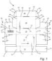
- the first blank 1 configured to be erected or folded into a package 200 will be described in detail with reference to Fig. 1 .
- the first blank 1 comprises a bottom panel 10, a rear wall panel 20, two sets of side wall panels 30, 40, a lid panel 50, and a first front panel 60.
- the bottom panel 10 may form a bottom 210 of the package 200.
- the rear wall panel 20 may form a rear wall 220 of the package 200.
- the rear wall panel 20 may be foldably connected to a longitudinally extending edge 12 of the bottom panel 10.
- the two sets of side wall panels 30, 40 may form opposing side walls 230, 240 of the package 200.
- the two sets of side wall panels 30, 40 may be foldably connected to a respective one of two transversally extending edges 23, 24 of the rear wall panel 20.
- the lid panel 50 may form a lid 250 of the package 200.
- the lid panel 50 may be foldably connected to a longitudinally extending first edge 21 of the rear wall panel 20.
- the first front panel 60 may be foldably connected to the lid panel 50 along a longitudinally extending edge 55 of the lid panel 50.
- the first front panel 60 may form a front 260 of the package 200.
- the front 260 may form part of the lid 250.
- the panels of the first blank 1 may be foldably connected to each other in a number of different of ways with remained function.
- the two sets of side wall panels 30, 40 are not necessarily limited to being foldably connected to a respective one of two transversally extending edges 23, 24 of the rear wall panel 20. It is conceivable that the two sets of side wall panels 30, 40 may be foldably connected to a respective one of two transversally extending edges of the bottom panel 10.
- the rear wall panel 20 may be provided with locking panels in a manner similar to the front locking panels 71, 72 foldably connected to the main front panel 70.
- Each of the two sets of side wall panels 30, 40 may comprise a first side wall panel 31, 41 and a second side wall panel 32, 42.
- the respective first side wall panel 31, 41 may form a respective first side wall 231, 241 of the package 200.
- the respective second side wall panel 32, 42 may form a respective second side wall 232, 242 of the package 200.
- the first side wall panel 31, 41 and the second side wall panel 32, 42 of the respective set of side wall panels may be foldably connected to each other and arranged one after the other in a direction extending away from the bottom panel 10. As illustrated in Fig. 1 , the respective first side wall panel 31, 41 may be foldably connected to the respective one of two transversally extending edges 23, 24 of the rear wall panel 20.
- the two sets of side wall panels 30, 40 may include a respective double fold line between the first side wall panel 31, 41 and the second side wall panel 32, 42.
- the respective double fold line may comprise a set of a first fold line 37, 47 and a second fold line 38, 48.
- the respective first fold line 37, 47 may be positioned closest to the respective first side wall panel 31, 41.
- the respective set of the first fold line 37, 47 and the second fold line 38, 48 may define a respective intermediate panel 39, 49.
- the respective intermediate panel 39, 49 has a transversal extension, as seen in the flat-laid state of the first blank 1, which is in the order of about one or two times the thickness of the first blank 1.
- the respective intermediate panel 39, 49 has a transversal extension such that the locking panels 71, 72 may be inserted between the side wall panels 31, 32, 41, 42 forming the respective double-walled side wall 230, 240.
- the respective intermediate panel 39, 49 has preferably a transversal extension in the order of two times the thickness of the first blank 1 such that both the locking panels 71, 72 of the main front panel 70 and the locking panels 61, 62 of the first front panel 60 may be inserted between the side wall panels 31, 32, 41, 42.
- An advantage with the double fold lines is the provision of a pronounced folding of the package 200 thereby facilitating handling of the package 200.
- the double fold lines and thus the respective intermediate panel 39, 49 may be omitted.
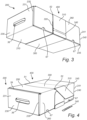
- Each set 30, 40 of side wall panels 31, 32, 41, 42 may be configured to form double-walled side walls 230, 240 of the package 200. This is best seen in Fig. 5 .
- the first side wall panel 31, 41 may be configured to form an outer surface of the respective double-walled side wall 230, 240.
- the second side wall panel 32, 42 may be configured to form an inner surface of the respective double-walled side wall 230, 240.
- the first side wall panel 31, 41 and the second side wall panel 32, 42 of the respective double-walled side walls 230, 240 may extend in parallel with each other.
- the respective intermediate panel 39, 49 may form an upper surface of the double-walled side wall 230, 240 of the package 200.
- the respective intermediate panel 39, 49 may be substantially perpendicular to both of the first side wall 31, 41 and the second side wall 32, 42 of the respective double-walled side wall 230, 240.
- the intermediate panel 39, 49 of the respective double-walled side wall 230, 240 may form a planar surface.
- the intermediate panel 39, 49 of the respective double-walled side wall 230, 240 may form a rounded surface.
- the double-walled side walls 230, 240 may be oppositely arranged as seen along the longitudinal direction L.
- the second side wall panels 32, 42 may comprise a respective locking tab 33, 43 having a longitudinal extension and extending transversely outwardly from a longitudinally extending side of the respective second side wall 32, 42 being opposite the respective first side wall panel 31, 41 as seen in a flat-laid state of the first blank 1.
- the respective locking tab 33, 43 is configured to interact with another panel 80, 90 and/or a recess 83, 93 and thereby keep the double-walled side walls 230, 240 in the folded position. This is best seen in Fig. 5 .
- the respective locking tab 33, 43 may be configured to be attached to another panel by means of e.g., adhesion or any other means normally used in the art.
- the respective locking tab 33, 43 may be configured to be attached to the bottom panel 10 by means of e.g., adhesion or any other means normally used in the art.
- the respective locking tab 33, 43 may be foldably connected to a free outer longitudinally extending edge of the respective second side wall panel 32, 42.
- the respective locking tab 33, 43 may be foldably connected to a free outer transversally extending edge of the respective side wall panel 32, 42.
- the respective locking tab 33, 43 may be foldably connected to a corner portion of the respective second side wall panel 32, 42.
- the respective locking tab 33, 43 is not necessarily foldably connected to the respective second side wall panel 32, 42, but may be connected to the respective side wall panel 32, 42 by means of e.g., adhesion or any other means normally used in the art.
- the locking tab 33, 43 of the respective second side wall panel 32, 42 may be internally formed by a cut.
- the first blank 1 may further comprise at least one bottom locking panel 80, 90. As illustrated in Fig. 1 , the first blank 1 comprises two bottom locking panels 80, 90. However, it may be noted that the first blank 1 may comprise more than two bottom locking panels 80, 90. Alternatively, it may be conceivable that the first blank 1 comprises a single bottom panel 80. In the following, the use of the term respective should not be understood as the first blank 1 necessarily being limited to comprising two bottom panels 80, 90, but the term respective is rather used in the context of describing the first blank 1 according to a first embodiment, which embodiment happens to comprise two bottom panels 80, 90.
- the respective bottom locking panel 80, 90 may be foldably connected to a longitudinally extending edge, opposite the first fold line 37, 47 of the respective double fold line.
- the respective bottom locking panel 80, 90 may be configured to be arranged on the bottom panel 10.
- the arrangement of the respective bottom locking panel is best seen in Fig. 5 .
- the respective bottom locking panel 80, 90 may be configured to be in parallel with the bottom panel 10.
- the respective locking tab 33, 43 may be configured to interact with the respective bottom locking panel 80, 90 and thereby keep the double-walled side walls 230, 240 in the folded position.
- the respective locking tab 33, 43 may be configured to be attached to the respective bottom panel 80, 90 by means of e.g., adhesion or any other means normally used in the art.
- the first blank 1 may comprise at least one opening 83, 93.
- the at least one opening 83, 93 may be provided in the respective bottom panel 80, 90.
- the respective opening 83, 93 may be configured to receive the respective locking tab 33, 43 and thereby keep the double-walled side walls 230, 240 in the folded position.
- the respective locking tab 33, 43 may be inserted into the respective opening 83, 93.
- the respective locking tab 33, 43 may be dimensioned slightly larger than the respective opening 83, 93, hence requiring a slight force to allow the respective locking tab 33, 43 to be inserted into the respective opening 83, 93. This would ensure that the respective double-walled side walls 230, 240 would be kept in its folded position.
- the respective locking tab 33, 43 may be dimensioned equal to, or slightly smaller than the respective opening 83, 93.
- the respective second side wall panel 32, 42 may be slightly bent in order for the respective locking tab 33, 43 to be able to be inserted through the respective opening 83, 93.
- the respective locking tab 33, 43 may thus abut a perimeter of the respective opening 83, 93 and keep the double-walled side walls 230, 240 in their folded position.
- the opening 83, 93 may be provided as small through-going openings in the respective bottom locking panel 80, 90.
- the respective opening 83, 93 may have a part of its circumference coinciding with the longitudinally extending edge along which the respective bottom wall panel 80, 90 is foldably connected to the respective first side wall panel 31, 41.
- the respective opening 83, 93 may be a slit, a hole, or the like.
- the locking tabs 33, 43 may be configured to interact with any panels of the package 200 depending on the design of the first blank 1. For instance, the locking tabs 33, 43 may be arranged on the respective second side wall panel 32, 42 such that the locking tabs 33, 43 interact with the main front panel 70 instead.
- the first blank 1 may be provided with at least one through-going hole, an opening, or the like, acting as a handle 36.
- the handle 36 may e.g., be provided as a small through-going opening in the first side wall panel 31.
- any panel of the first blank 1 may be provided with a through-going hole, an opening, or the like, acting as a handle for handling the package 200.
- the first side wall panel 41 or the rear wall panel 20 may be provided with a handle 36. It may be noted that the first blank 1 is not necessarily limited to being provided with a single handle 36 but may be provided with a plurality of handles 36 in order to further facilitate handling of the package 200.
- the material in the handles may still be present, but may be easily pushed inwardly or outwardly by being defined by a perforation forming a loop around said handle handles 36.
- the handle 36 may be formed by an internal tab formed by a through-going cut and which internal tab is foldable relative to the panel in which the internal tab is provided.
- the handle 36 may be formed of a strap formed of e.g., paper or plastic, being attached to the package 200.
- the strap may be directly attached to any panels of the package 200.
- the strap may extend through a through-going opening provided in the first side wall panel 31, 41 of one of the double-walled side walls 230, 240, and any other layer being positioned inside the respective double-walled side wall 230, 240, and be attached to the second side wall panel 32, 42, or to another layer being positioned between the first side wall panel 31, 41 and the second side wall panel 32, 42, of said one of the double-walled side walls 230, 240.
- the strap extends through a respective through-going opening provided in any of the panels adjacent to the panel which the strap is configured to be attached to.
- the handle 36 being formed by a strap being configured to be attached to the package 200, preferably the second side wall panel 32, 42, or another layer being positioned between the first side wall panel 31, 41 and the second side wall panel 32, 42 of the respective double-walled side walls 230, 240, there is provided a package 200 that is capable of withstanding mechanical deformation when the package 200 is held by the handle 36.
- the lid panel 50 and the bottom panel 10 may form a lid 250 and a bottom 210, respectively, that are configured to be parallel with each other.
- the lid panel 50 may comprise two lid side wall panels 53, 54 being foldably connected to a respective one of two first transversally extending edges 56, 57 of the lid panel 50.
- Each of the lid side wall panel 53, 54 may be configured to extend along an inside surface of the respective double-walled side walls 230, 240 of the package 200.
- the first front panel 60 may comprise two front locking panels 61, 62 being foldably connected to a respective one of two transversally extending edges 63, 64 of the first front panel 60.
- Each of the front locking panel 61, 62 may be configured to extend into front slits 235, 245 formed between the side wall panels 31, 32, 41, 42 of the respective double-walled side walls 230, 240 of the package 200.
- the first front panel 60 may comprise at least one through-going recess 67 formed by a cut.
- the recess 67 may be configured to facilitate unlocking the lid panel 50.
- the recess 67 may be positioned along a free outer longitudinally extending edge of the first front panel 60.
- a portion of a perimeter of the recess 67 may connect with said free outer longitudinally extending edge of the first front panel 60.
- a portion of the recess 67 may be open-ended.
- the recess 67 is an internal cut-out in the first front panel 60.
- the first blank 1 may further comprise a main front panel 70 being foldably connected to the bottom panel 10 along a longitudinally extending edge 11 of the bottom panel 10.
- the main front panel 70 may be oppositely arranged relative the rear wall panel 20.
- the first front panel 60 and the main front panel 70 may have, in an erected state of the first blank 1, overlapping projections in a plane perpendicular to the lid panel 50.
- the first front panel 60 may be configured to abut an outside surface of the main front panel 70. It may be noted that the first front panel 60 may not necessarily be limited to being configured to abut an outside surface of the main front panel 70. On the contrary, there may be a small gap between the first front panel 60 and the main front panel 70 when the first front panel 60 and the main front panel 70 are in their intended positions. Also, alternatively, the first front panel 60 may be designed to extend inside the main front panel 70.
- the main front panel 70 may comprise two main locking panels 71, 72 being foldably connected to a respective one of two transversally extending edges 73, 74 of the main front panel 70.
- Each of the main locking panel 71, 72 may be configured to be inserted into the front slits 235, 245 formed between the side wall panels 31, 32, 41, 42 of the respective double-walled side walls 230, 240 of the package 200.
- the main lock locking panels 71, 72 may have, as seen in a flat-laid state of the first blank 1, an extension, as measured along a longitudinal direction L, being approximately equal to a transversal extension of the bottom panel 10. Hence, the main locking panels 71, 72 may, in an erected state of the first blank 1, extend along the complete extension of the side walls 230, 240 along the bottom panel 10 and may even be configured to abut the rear wall panel 20. This is advantageous since the double-walled side walls 230, 240 thereby are provided with enhanced structural integrity along the extension of the double-walled side walls 230, 240.
- the main locking panels 71, 72 may have a transversal extension being just slightly less than the transversal extension the rear wall 20, i.e., slightly less than the intended height of the package 200 such that the main locking panels 71, 72 basically extend inside the whole height of the double-walled side walls 230, 240.
- the first blank 1 comprises a first slit 51 in a connection between the lid panel 50 and the rear wall panel 20.
- the first slit 51 may be provided in the lid panel 50 in the vicinity of the connection between the lid panel 50 and the rear wall panel 20.
- the first slit 51 may, as seen in a flat-laid state of the first blank 1, be separated from the connection between the lid panel 50 and the rear wall panel 20 along the lid panel 50 a distance, as measured along the transversal direction T, being 30%, preferably 15%, of a transversal extension of the of the lid panel 50.
- the first blank 1 may further comprise a second slit 52 in a connection between the lid panel 50 and the first front panel 60.
- the second slit 52 may be provided in the lid panel 50 in the vicinity of the connection between the lid panel 50 and the first front panel 60.
- the second slit 52 may, as seen in a flat-laid state of the first blank 1, be separated from the connection between the lid panel 50 and the first front panel 60 along the lid panel 50 a distance, as measured along the transversal direction T, being 30%, preferably 15%, of a transversal extension of the lid panel 50.
- the second slit 52 may be provided in the first front panel 60 in the vicinity of the connection between the lid panel 50 and the first front panel 60.
- the second slit 52 may, as seen in a flat-laid state of the first blank 1, be separated from the connection between the lid panel 50 and the first front panel 60 along the first front panel 60 a distance, as measured along the transversal direction T. Hence, the second slit 52 may be provided in the first front panel 60. However, in such a case the second slit 52 is preferably arranged within 10% of a transversal extension of the first front panel 60.
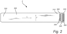
- the second blank 2 comprises an elongated body part 300 comprising a first and a second connection portion 310, 320.
- the two connection portions 310, 320 may form part of a respective oppositely arranged end portion of the elongated body part 300.
- the two connection portions 310, 320 are configured to be connected to each other such that the elongated body part 300 forms a continuous loop.
- the first connection portion 310 of the elongated body part 300 may be inserted through the first slit 51 along a first circumferential direction of the package 200.
- the first slit 51 allows the elongated body part 300 of the second blank 2 to extend into the package 200 formed of the first blank 1.
- the elongated body part 300 may then extend along an inwardly facing major surface of the lid panel 50 and be inserted into the second slit 52.
- the second slit 52 allows the elongated body part 300 of the second blank 2 to extend out from the package 200 formed of the first blank 1.
- the first slit 51 is provided in the connection between the lid panel 50 and the rear wall panel 20.
- the second slit 52 is provided in the connection between the lid panel 50 and the first front panel 60.
- the second slit 52 may be provided in the first front panel 60 in the vicinity of the connection between the lid panel 50 and the first front panel 60. It may thus be conceivable that the elongated body part 300 extends diagonally from the first slit 51 to the second slit 52.
- the main front panel 70 may have, as seen in a flat-laid state of the first blank 1, a length L1 along the transversal direction T such that a longitudinally extending edge of the main front panel 70 is configured to abut the lid panel 50 when the first blank 1 is erected into a package 200. It may be noted that the main front panel 70 may alternatively be configured to abut the elongated body part 300, or the elongated body part 300 and the lid panel 50.
- said longitudinally extending edge of the main front panel 70 may push up the diagonally extending elongated body part 300 such that the elongated body part 300 abuts, or at least is arranged in the vicinity of, the inwardly facing major surface of the lid panel 50 hence the elongated body part 300 occupying less space in the internal space of the package 200 and thereby allow items to further fill out the internal space of the package 200.
- said longitudinally extending edge of the main front panel 70 may terminate at a distance from the lid panel 50 when the first blank 1 is erected into a package 200.
- the second connection portion 320 of the elongated body part 300 may extend along a second circumferential direction, opposite the first circumferential direction, of the package 200.
- the second blank 2 may, as seen in a flat-laid state of the second blank 2, have a longitudinal extension being greater than a circumferential extension of an assembled package 200 thereby allowing the two connection portions 310, 320 of the elongated body part 300 to overlap.
- one of the overlapping connection portions 310, 320 may form an outer connection portion and the other one may form an inner connection portion.
- the first connection portion 310 forms the outer connection portion
- the second connection portion 320 forms the inner connection portion.
- connection portions 310, 320 are connected to each other thereby allowing the elongated body part 300 to form a closed loop closure strap 400.
- the connection portions 310, 320 may be connected to each other in a number of different ways.
- the second blank 2 may be provided with a first adhesive strip 330 adhesively connecting the connection portion 310, 320.
- the first connection portion 310 may be provided with the first adhesive strip 330.
- the second connection portion 320 may be provided with the first adhesive strip 330.
- both of the connection portions 310, 320 may be provided with a respective first adhesive strip 330.
- the first adhesive strip 330 may be arranged in the vicinity of a transversally extending edge portion, preferably a transversally extending free outer edge, of the second blank 2.
- the first adhesive strip 330 may extend transversally between two opposing longitudinally extending edges, or edge portions, of the second blank 2.
- connection portions 310, 320 may be adhesively connected to each other by means of tape.
- connection portions 310, 320 may be connected to each other without any means of adhesive, or the like.
- the first connection portion 310 may comprise a first slit.
- the second connection portion 320 may be provided with a first internal attachment tab configured to engage with the first slit and thereby keep the closure strap 400 in its intended position.
- the second blank 2 may further be provided with a tear strip 340 allowing the continuous loop to be broken.
- a tear strip may be a local weakening and/or a local strengthening making it easier to achieve a tearing operation along an intended tear line.
- a local weakening may e.g., be a line of perforations or a crease line. The line of perforations may extend along the complete length of the intended tear line or may alternatively just provide an initial tear indication.
- a local strengthening may e.g., be a plastic tape laminated into or provided onto a paper-based blank. In the disclosed embodiment there is made use of short perforations or cuts providing tear indications basically extending along the length of the intended tear line.
- the first connection portion 310 may be provided with the tear strip 340.
- the second connection portion 320 may be provided with the tear strip 340.
- the tear strip 340 may be arranged in the vicinity of a transversally extending edge portion of the second blank 2.
- the tear strip 340 may extend transversally between two opposing longitudinally extending edges, or edge portions, of the second blank 2.
- the tear strip 340 may be separated from the first adhesive strip 330, both as seen in flat-laid state of the second blank 2 and when the second blank 2 has formed a continuous loop where the connection portions 310, 320 are overlapping with each other.
- the tear strip 340 is arranged on the connection portion being configured to form an outer connection portion of the overlapping connection portions 310, 320.
- the tear strip 340 may be arranged, as seen when the elongated body part 300 of the second blank 2 has formed a continuous loop, a distance to a transversally extending edge portion of the connection portion being configured to form an outer connection portion 310 of the overlapping connection portions 310, 320 being greater than the distance between the first adhesive strip 330 and said transversally extending edge portion. This is advantageous since it allows the two connection portions 310, 320 to overlap and connect to each other, while allowing the continuous loop to be broken by tearing the tear strip 340.
- the second blank 2 may be provided with a second adhesive strip 350 allowing the elongated body part 300 to be reassembled into a continuous loop.
- the first connection portion 310 may be provided with the second adhesive strip 350.
- the second connection portion 320 may be provided with the second adhesive strip 350.
- both of the connection portions 310, 320 may be provided with a respective second adhesive strip 350.
- the second adhesive strip 350 may extend transversally between two opposing longitudinally extending edges, or edge portions, of the second blank 2.
- the elongated body part 300 may be reassembled into a continuous loop by means of tape.
- the elongated body part 300 may be reassembled into a continuous loop without any means of adhesive, or the like.
- the first connection portion 310 may comprise a second slit.
- the second connection portion 320 may be provided with a second internal attachment tab configured to engage with the second slit and thereby keep the closure strap 400 in its intended position.
- the second adhesive strip 350 may be arranged, as seen when the elongated body part 300 of the second blank 2 has formed a continuous loop, a distance to a transversally extending edge portion of the connection portion being configured to form an outer connection portion 310 of the overlapping connection portions 310, 320 being greater than the distance between the tear strip 340 and said transversally extending edge portion. This is advantageous since it allows the continuous loop to be broken by tearing the tear strip 340, while allowing the elongated body part 300 to be reassembled into a continuous loop.
- the first adhesive strip 330 and the second adhesive strip 350 are arranged on the same connection portion 310, 320. This is advantageous in that it facilitates handling the elongated body part 300 and forming the closure strap 400 since a user may hold one of the connection portions not provided with any adhesive strips while forming the continuous loop.
- the second adhesive strip 350 and also preferably the first adhesive strip 330, may be provided with a protective film 360.
- the protective film 360 may be made of plastic, or any other suitable material normally used in the art that do not substantially affect the adhesive strength of either of the adhesive strips 330, 350 when the protective film 360 has been removed.
- the tear strip 340 has been removed by a pulling movement.
- the tear strip 340 as illustrated in Fig. 4 extends between two opposing free outer longitudinally extending edges of the elongated body part 300.
- the removal of the tear strip 340 is initialized by a pulling movement of an end of the tear strip 340 starting from either one of the two opposing free outer longitudinally extending edges of the elongated body part 300.
- a portion of the first connection portion 310 being provided with the first adhesive strip 330 is adhered to the second connection portion 320.
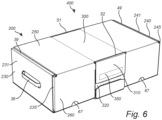
- the lid 50 has been unlocked and the internal space of the package 200 is revealed. Further, the second adhesive strip 350 provided on an inside surface of the first connection portion 310 is revealed. The plastic film 360 provided on the second adhesive strip 350 is removed in order to initialize the reassembling of the elongated body part 300 into a continuous loop. In order to reassemble the elongated body part 300, the lid 250 is closed and the first connection portion 310 may be folded onto an outside surface of the second connection portion 320. The second adhesive strip 350 may then adhesively connect the two connection portions 310, 320.
- Fig. 6 illustrates the elongated body part 300 reassembled into a continuous loop.
- the first blank 1 is preferably made of a paper-based material.
- An advantage with the first blank 1 being paper-based is that paper-based materials are recyclable hence making efficient use of the material. Paper-based materials are also renewable and sustainable. It is also comparably easy to cut a sheet of paper-based material into the desired shape of the first blank 1. It is also comparably easy to fold a paper-based first blank 1 into the desired package 200.
- the paper-based material may comprise a corrugated layer with flutes. The flutes of the corrugated layer may extend along the longitudinal direction L. However, the flutes of the corrugated layer may alternatively extend along the transversal direction T.
- the first blank 1 may be made of any material normally used in the art for packaging. By way of example, the first blank 1 may be made of plastic or wood-based materials.
- the second blank 2 is preferably made of a paper-based material.
- An advantage with the second blank 2 being paper-based is that paper-based materials are recyclable hence making efficient use of the material. Paper-based materials are also renewable and sustainable. It is also comparably easy to cut a sheet of paper-based material into the desired shape of the second blank 2. It is also comparably easy to fold a paper-based second blank 2 into the desired closure strap 400.
- the paper-based material may comprise a corrugated layer with flutes. The flutes of the corrugated layer may extend along the longitudinal direction L. However, the flutes of the corrugated layer may alternatively extend along the transversal direction T.
- the second blank 2 may be made of any material normally used in the art for packaging. By way of example, the second blank 2 may be made of plastic or wood-based materials.
Landscapes
- Engineering & Computer Science (AREA)
- Mechanical Engineering (AREA)
- Cartons (AREA)
Abstract
Description
- The invention relates to a kit of blanks. The invention also relates to a package, the package being folded from a kit of blanks.
- When designing a package, it is often desirous to take into account a number of different design criteria. The package should e.g., often be designed such that it makes efficient use of the material, is easy to transport to the point of use, is easy to prepare for use, and is mechanically stable. It is often desirable that the package is convenient to handle at the point of use and remains closed during handling and transportation. It is also often desirable that the package is reusable.
- Packages used in e.g., e-commerce are occasionally returned by the customer. Once the customer has decided to return the package, the package should easily be resealed or reclosed. The package might be provided with a resealable or reclosable mechanism, often comprising the use of adhesives or the like. At times, the package is not provided with a resealable or reclosable mechanism. In that case, the customer may reseal or reclose the package by means of e.g., an external adhesive, such as tape or glue.
- However, resealing or reclosing the package using means of adhesive or the like may run the risk of damaging the package. A damaged package may render the package unfit for reuse. The use of adhesive typically also makes the package difficult to disassemble and recycle at time of disposal.
- There exist numerous attempts to address the above design criteria in connection to designing a package of cardboard material.
-
WO 2016/064975 A1 discloses a package for holding a product. The package may comprise a liner for receiving the product and at least partially wrapping around the product. - However, it may be noted that the prior art document does not adequately address the set of design criteria that the package should be designed such that it makes efficient use of the material, is easy to transport to the point of use, is easy to prepare for use, and is mechanically stable. Moreover, the prior art document does not adequately address the set of design criteria that the package should be convenient to handle at the point of use, remain closed during handling and transportation, and be reusable.
- It is an object of the invention to provide a solution addressing at least some of the design criteria that the package should make efficient use of the material, is easy to transport to the point of use, is easy to prepare for use, and is mechanically stable. It is also an object of the invention to provide a package being convenient to handle at the point of use, being able to remain closed during handling and transportation, and being reusable.
- This object has been achieved by a kit of blanks comprising a first blank configured to form a package and a second blank configured to form a closure strap aiding in keeping the package closed, wherein
- the first blank comprises
- a bottom panel,
- a rear wall panel,
- two sets of side wall panels,
- a lid panel being foldably connected to the rear wall panel, and
- a first front panel being foldably connected to the lid panel,
- wherein the second blank comprises
- an elongated body part comprising a first and a second connection portion being configured to be connected to each other such that the elongated body part forms a continuous loop,
- wherein the first blank further comprises
- a first slit in a connection between the lid panel and the rear wall panel, or in the lid panel in the vicinity of the connection between the lid panel and the rear wall panel, the first slit allowing the elongated body part of the second blank to extend into the package formed of the first blank and alongside an inside of the lid panel, and
- a second slit in a connection between the lid panel and the first front panel, or in the first front panel or in the lid panel in the vicinity of the connection between the lid panel and the first front panel, the second slit allowing the elongated body part of the second blank to extend out from the package formed of the first blank.
- An advantage with this design is that the first and second slits allow the elongated body part to extend through a top portion of the package. Preferably, the elongated body part extends essentially alongside the lid panel. The elongated body part extends into the package by being inserted into the first slit, wherefrom it extends inside the package essentially alongside the lid panel, and from where the elongated body part extends out from the package through the second slit. From the first slit and as seen in the other direction, the closure strap extends alongside an outside of the rear wall panel, alongside an outside of the bottom panel, and up alongside an outside of the front of the package. The elongated body part may have such a length along its longitudinal direction, as seen in a flat-laid state of the second blank, that the elongated body part may extend circumferentially around the package, along the transversal direction of the first blank as seen in a flat-laid state of the first blank, such that that the first connection portion of the elongated body part may connect to the second connection portion of the elongated body part and thereby form a continuous loop. Preferably, the first and second connection portions overlap with each other. The continuous loop may be formed such that the elongated body part forms a closure strap being pre-tensioned or so close to being tensioned that any slight opening of the lid will cause the closure strap to being tensioned. A major portion of the elongated body part may thus abut the package. Preferably, a major portion of the elongated body part is pressed against the package. The friction therebetween may keep the elongated body part in its intended position. Hence, there is avoided that the elongated body part forms a flimsy closure strap which otherwise might risk being caught on an object when the package is being handled. By the elongated body part forming a tensioned closure strap there is provided a package being convenient to handle.
- Another advantage with this design is that the slits allow the elongated body part and the package to be interconnected. The elongated body part facilitates in keeping the lid panel in its intended position. The slits allow the elongated body part to extend along an inwardly facing major surface of the lid panel. Preferably, the elongated body part straddles the inwardly facing major surface of the lid panel hence occupying minimal space in the internal space of the package and thereby allow items to fully fill out the internal space of the package. By the elongated body part forming a closure strap and being configured to extend along an inwardly facing major surface of the lid panel, the elongated body part provides the lid panel internal support points. This, at least partly, prevents the closure strap from collapsing inwardly. Hence, this configuration of the slits and the elongated body part provides a package capable of remaining mechanically strong over a sufficient time period and allows a plurality of packages to be sturdily stacked on top of each other. It may be noted that the positions of the first and second slits may be designed in a number of different ways. The first slit may, as seen in a flat-laid state of the first blank, be separated from the connection between the lid panel and the rear wall panel along the lid panel a distance, as measured along the transversal direction, the distance being less than 30%, preferably less than 15%, of a transversal extension of the lid panel. Similarly, the second slit may, as seen in a flat-laid state of the first blank, be separated from the connection between the lid panel and the first front panel along the lid panel a distance, as measured along the transversal direction, the distance less than being 30%, preferably less than 15%, of a transversal extension of the lid panel. Alternatively, the second slit may be provided in the first front panel in the vicinity of the connection between the lid panel and the first front panel. The second slit may, as seen in a flat-laid state of the first blank, be separated from the connection between the lid panel and the first front panel along the first front panel a distance, as measured along the transversal direction, being 30%, preferably 15%, of a transversal extension of the first front panel, as seen in a flat-laid state of the blank. Hence, the second slit may be provided in the first front panel. This design of the respective first and second slit is advantageous in that it is, at least partly, ensured that the elongated body part is provided sufficient leverages to suspend the lid panel, and that the lid panel is provided with sufficient enough internal support points to reduce the risks of the lid panel collapsing inwardly as a plurality of packages are stacked on top of each other.
- Another advantage with this design is that by the second blank being configured to form a closure strap aiding in keeping the package closed, and by the closure strap and the package being interconnected, the package may be closed without the use of any adhesive or similar means, or at least with a minimum use of such adhesive or similar means. Preferably, the package is assembled without the use of any adhesive or similar means, or at least with a minimum use of such adhesive or similar means. By using adhesive to close the package, the package may be tarnished. Any adhesive used on the package may cause the package to be damaged during disassembling of the package in that certain parts of the surface of the package might be ripped off during disassembling of the package, and consequently might even lead to deformation of the blank if the adhesive is adhered to the any surface too strongly. The use of adhesive may also make the package difficult to disassemble and recycle at time of disposal. However, with this design, the closure strap aids in keeping the package closed. This also makes efficient use of material and provides a package capable of being designed to be reusable. For instance, a package may be returned should the user e.g., regret purchasing a certain product, or fail to obtain the package from a provider within an allowable time period hence the package being sent back to where it came from. This design allows for the closure strap to be removed without damaging the package. Hence, the closure strap allows for multiple uses of the first blank configured to form the package.
- Another advantage with this design is that the first front panel may be folded into an intended position such that the first front panel forms part of a front wall of the package. The elongated body part may form a closure strap such that a portion of the closure strap overlaps with the first front panel. By the elongated body part forming a closure strap, preferably a tensioned closure strap, around the package, it is avoided that the first front panel is removed from its intended position by accidently unfolding outwardly away from the internal space of the package. Stored items may occupy a major portion of the internal space. By the stored items occupying a major portion of the internal space of the package it is avoided that the first front panel is removed from its intended position by accidently folding inwardly towards the lid panel. The stored items may thus press the first front panel against the closure strap. Hence, the first front panel may form a side wall of the package and be kept in its intended position by the closure strap and the stored items acting on the first front panel. This design, at least partly, prevents stored items from falling out of the package, or being displaced from the internal space of the package, and provides stored items protection from external forces.
- The first blank may further comprise a main front panel being foldably connected to the bottom panel along a longitudinally extending edge of the bottom panel, wherein the first front panel and the main front panel have, in an erected state of the first blank, at least partly overlapping projections in a plane perpendicular to the lid panel.
- An advantage with this design is that the main front panel may be folded into an intended position such that the main front panel forms part of a side wall of the package. The first front panel and the main front panel may, in their intended positions, be substantially in parallel with each other and have overlapping projections in a plane perpendicular to the lid panel. Preferably, the first front panel is configured to abut an outside surface of the main front panel. By this design, there is formed a double-walled side wall comprising the first front and the main front panel. This double-walled side wall provides a thickness capable of withstanding mechanical deformation.
- It may be noted that by the first front panel and the main front panel having overlapping projections in a plane perpendicular to the lid panel, the first front panel is not necessarily limited to being configured to abut an outside surface of the main front panel. On the contrary, there may be a small gap between the first front panel and the main front panel when the first front panel and the main front panel are in their intended positions. By the closure strap, the first front panel is prevented from accidently unfolding outwardly away from the internal space of the package. Accordingly, the main front panel is prevented from accidently unfolding outwardly away from the internal space of the package by the first front panel being configured to be arranged adjacently the main front panel. Stored items occupying a major portion of the internal space of the package may press against the main front panel hence it is avoided that the main front panel is removed from its intended position by accidently folding inwardly towards the bottom panel. Thus, with this design there is provided a double-walled side wall capable of being kept in its intended position by the closure strap acting on the first front panel and the stored items acting on the main front panel. The double-walled side wall further, at least partly, prevents stored items from falling out of the package, and provides stored items protection from external forces.
- The respective set of the two sets of side wall panels may comprise a first side wall panel and a second side wall panel being foldably connected to each other and arranged one after the other in a direction extending away from the bottom panel, and wherein each set of side wall panels is configured to form a respective double-walled side wall of the package.
- An advantage with this design is that the double-walled side walls provide a mechanically strong structure. The double-walled side walls provide a total material thickness capable of withstanding mechanical deformation. This allows e.g., for a plurality of packages to be securely stacked on top of each other. It may be noted that the double-walled side walls may include more than two layers of material; the first and second side wall panels and for instance a respective front locking panel which is positioned between the first and second side wall panel forming the respective double-walled side wall when the kit of blanks is erected to form the package. However, the term double-walled is herein intended to refer to the fact that the respective side wall is formed of two major side wall panels being connected to and folded relative to each other irrespective of if there is or is not any additional panels inserted therebetween.
- The main front panel may comprise two main locking panels being foldably connected to a respective one of two first transversally extending edges of the main front panel, wherein each of the main locking panel preferably is configured to extend into front slits formed between the side wall panels of the respective double-walled side walls of the package.
- Typically, the main locking panels are positioned in the intended position and thereafter the second side wall panels are folded to form the double-walled side walls over the main locking panels and thereby locking the main locking panels therebetween and thereby locking the main front panel in the upright position.
- An advantage with this design is that the main locking panels facilitate in keeping the main front panel in its intended position. The main locking panels may be configured to be removably inserted into the front slits of the respective double-walled side walls of the package. Hence, this design facilitates in keeping main front panel in its intended position. This provides a stable main front panel when the first blank is erected to form the package. This also provides a package being capable of remaining closed during handling and transportation without the use of any adhesive or similar means, or at least with a minimum use of such adhesive or similar means.
- Another advantage with this design is that by removably inserting the main locking panels into the front slits of the respective double-walled side walls of the package, the double-walled side walls may be configured to include more than two layers of material. By positioning a main locking panel between the first and second side wall panels of the respective double-walled side walls there is provided a package having an enhanced structural integrity. During handling of the package, external forces may arise which is being directed towards the respective double-walled side walls. However, the impact of the external forces is, at least partly, reduced since the double-walled side walls are enhanced with the main locking panels being positioned between the first and second side wall panels of the respective double-walled side walls hence forming a resilient enclosure being able to absorb a portion of said impact of the external forces. Therefore, the stored items inside the internal space of the package are being protected from the external forces.
- The respective second side wall panel may be provided with a respective locking tab having a longitudinal extension and extending transversely outwardly from a longitudinally extending side of the respective second side wall being opposite the respective first side wall panel as seen in a flat-laid state of the first blank, wherein the respective locking tab is configured to interact with another panel and thereby keep the double-walled side walls in the folded position.
- An advantage with this design is that by the double-walled side walls being kept in the folded position there is provided a mechanically strong package. The respective locking tab may interact with the bottom panel or any other panel being configured to be arranged on the bottom panel. In the preferred embodiment, the respective locking tab interacts with a recess formed in said another panel. In one preferred embodiment, the recess is formed in the bottom panel. In another preferred embodiment, the first blank comprises another panel, such as a bottom locking panel which will be discussed below, which extends along the bottom panel. In such a case it is preferred that the locking tab interacts with such another panel by a recess in said another panel. It may be noted that panels of the first blank may be foldably connected to each other in a number of different ways with remained function. Hence, it is conceivable that the respective locking tab may not necessarily be limited to interact with the bottom panel, or any other panel being configured to be arranged on the bottom panel. On the contrary, the respective locking tab may be configured to interact with e.g., the lid panel, the main front panel, the first front panel, or any other panels of the first blank depending on how to first blank is designed. Furthermore, the respective locking tab may be integrally formed with the second side wall panels. By the respective locking tab being a part of a single blank forming the package, it is possible to make efficient use of material. As the package has locking tabs that may be formed from a single blank, the first blank is also easy to prepare for use, as opposed to attaching external locking tabs to the first blank or the package. Furthermore, this makes the first blank easy to transport to the point of use, considering that it is most often easier to transport a single unit rather than to transport several separate components configured to be assembled to form a single unit.
- The first blank may further comprise at least one bottom locking panel, preferably two bottom locking panels, each associated with a respective first side wall panel, the bottom locking panel or panels being configured to be arranged on the bottom panel, and wherein the respective locking tab is configured to interact with the bottom locking panel or panels and thereby keep the double-walled side walls in the folded position.
- An advantage with this design is that by the at least one bottom locking panel being configured to be arranged on the bottom panel there is provided a package having a double-walled bottom. This double-walled bottom may have a thickness capable of withstanding mechanical deformation.
- Another advantage with this design is that by the respective locking tab being configured to interact with the bottom locking panel and thereby keeping the double-walled side walls in the folded position, there is provided a package capable of being mechanically strong over a sufficient time period. Furthermore, by the bottom locking panels being configured to be arranged on the bottom panel, said bottom locking panels may reside inside the internal space of the package, as opposed to forming part of an outer wall, in this case the bottom panel, of the package. Thereby, when the package e.g., is being handled by a user or being transported, any external impacts or disturbances will mainly affect the bottom panel rather than any panel being arranged on the bottom panel. Hence, said external impacts or disturbances are, at least partly, prevented from compromising the intended position of the respective locking tab. In case the transversal extension of the bottom panel is longer than the longitudinal extension of the bottom panel, and/or if there is no locking panel on at least one of the sides of the main front panel, it is possible to have one bottom locking panel extending longitudinally across the whole bottom formed by the bottom panel. However, in the preferred embodiment, there is two bottom locking panels, each associated with a respective first side wall panel.
- The one or more bottom locking panels may each comprise at least one opening, the opening being configured to receive the respective locking tab of the second side wall panels and thereby keep the double-walled side walls in the folded position.
- An advantage with this design is that the locking tabs may be connected to the bottom locking panel or panels without use of any adhesive and allows for the double-walled side walls to be quickly formed upon folding the first blank into a package. Any adhesive used on the locking tabs or the bottom locking panel(s) may cause the surface of the locking tabs and the bottom locking panel(s) to be damaged during disassembling of the package in that the surface of the locking tabs and the bottom locking panel(s) might be ripped off during disassembling of the package, and consequently might even lead to deformation of the blank if the adhesive is adhered to the any surface too strongly. The use of adhesive may also make the package difficult to disassemble and recycle at time of disposal. However, with this design, the locking tabs are connected to the bottom locking panel or panels without use of adhesive hence the risk of damaging the locking tabs and the bottom locking panel(s) during disassembling of the package is reduced and allows for multiple uses of the blank, thereby making efficient use of material and providing a package capable of being reusable.
- The lid panel may comprise two lid side wall panels being foldably connected to a respective one of two first transversally extending edges of the lid panel, wherein each of the lid side wall panels is preferably configured to extend along an inside surface of the respective double-walled side walls of the package.
- The lid panel, the first front panel and the two lid side wall panels may be configured to form a lid of the package. When closing the lid by a hinging movement of the lid relative to the rear wall panel, the lid side wall panels may be folded inwardly to allow the lid side wall panels to extend along an inside surface of the respective double-walled side walls of the package. The lid side wall panels may thus be configured to abut an inside surface of the respective double-walled side walls of the package. Preferably, the lid side wall panels are configured to slightly exert an outwardly directed force on the inside surface of the respective double-walled side wall of the package, such that a slight pressure is applied on the respective double-walled side wall. An advantage with this design is that the friction therebetween facilitates in keeping the lid in its intended position. Hence, there is provided a stable lid and also a package that is able to remain closed during handling and transportation.
- Another advantage with this design is that the lid side wall panels may contribute to an additional thickness to the respective double-walled side wall hence providing a package capable of withstanding mechanical deformation.
- The lid side wall panels may, as seen in a flat-laid state of the first blank, have a longitudinal extension corresponding to the transversal extension of the rear wall panel, i.e., to the intended height of the package, such that the lid side wall panels abut the internal bottom of the package formed of the bottom panel or bottom locking panels.
- The first blank is preferably made of a paper-based material.
- The second blank is preferably made of a paper-based material.
- An advantage with the first and second blanks being paper-based is that paper-based materials are recyclable hence making efficient use of the material. Paper-based materials are also renewable and sustainable. It is also comparably easy to cut a sheet of paper-based material into the desired shape of the first and second blanks. It is also comparably easy to fold paper-based first and second blanks into the desired package and the closure strap, respectively. The paper-based material may comprise a corrugated layer with flutes. The flutes of the corrugated layer may extend along the longitudinal direction. However, the flutes of the corrugated layer may alternatively extend along the transversal direction. The first and second blanks may be made of any material normally used in the art for packaging. By way of example, the first and second blanks may be made of plastic or wood-based. The first and second blanks may be formed of different materials. It may in this context be noted that the environmental gain is greatest if the first blank is made from a paper-based material. Thus, it is conceivable that the first blank is made from a paper-based material and that the second blank is formed of another kind of material such as e.g., a polymer-based material.
- The first front panel may comprise two front locking panels being foldably connected to a respective one of two transversally extending edges of the first front panel, wherein each of the front locking panel is configured to be inserted into front slits formed between the side wall panels of the respective double-walled side walls of the package.
- An advantage with this design is that a locking of the lid, as the first blank is erected into a package, is facilitated. The front locking panels may be configured to be removably inserted into the front slits of the respective double-walled side walls of the package. Hence, this design facilitates in keeping the lid in its intended position. This provides a stable lid when the first blank is erected to form the package. This also provides a package being capable of remaining closed during handling and transportation without the use of any adhesive or similar means, or at least with a minimum use of such adhesive or similar means.
- Another advantage with this design is that by removably inserting the front locking panels into the front slits of the respective double-walled side walls of the package, the double-walled side walls may be configured to include more than two layers of material. By positioning a front locking panel between the first and second side wall panels of the respective double-walled side walls there is provided a package having an enhanced structural integrity. During handling of the package, external forces may arise which is being directed towards the respective double-walled side walls. However, the impact of the external forces is, at least partly, reduced since the double-walled side walls are enhanced with the front locking panels being positioned between the first and second side wall panels of the respective double-walled side walls hence forming a resilient enclosure being able to absorb a portion of said impact of the external forces. Therefore, the stored items inside the internal space of the package is being protected from the external forces.
- The second blank may be provided with a tear strip allowing the continuous loop to be broken.
- An advantage with this design is that the continuous loop may be broken conveniently and distinctly. The continuous loop may be broken without e.g., the use of any tools such as a scissor, or a user forcefully tearing the elongated body part in which case upon tearing the elongated body part, stress would increase along areas of a tearing path of the elongated body part in an uncontrolled manner and thus the elongated body part would be teared apart in a manner where the edges formed along the tearing path would end up rough and untidy which would e.g., prevent the elongated body part to be reassembled into continuous loop.
- The second blank may be provided with a first adhesive strip arranged to adhesively connect the connection portions.
- An advantage with this design is that upon forming the continuous loop, the connection portions may, at least partly, overlap with each other such that an oppositely arranged major surface of the first and second connection portions may be adhesively connected to each other. The adhesive strip being present on the second blank may facilitate initial closing of the package since the piece with the adhesive properties is already present.
- The second blank may be provided with a second adhesive strip arranged to adhesively connect the connection portions and thereby allow the elongated body part to be reassembled into a continuous loop.
- An advantage with this design is that there is provided an elongated body part capable of being reassembled into a continuous loop without tarnishing the surface of the package. The package may hence be reusable in a convenient manner. It may in this context be noted that the adhesive strip referred to as the first adhesive strip may be omitted and still the adhesive strip referred to as the second adhesive strip may be present. It is e.g., conceivable that the first adhesive strip is replaced with a glue or the like since that connection of the connection portions is typically performed at a distribution site where additional equipment, such as a gluing apparatus may be present. The second adhesive strip is however typically made use of at the recipient end, such as at a consumer's home, when the package is reclosed for returning some or all of the goods therein. Thereby, it is convenient if there is already an adhesive strip present and it is also advantageous by the second adhesive strip already being in the intended position allowing the elongated body part to be reassembled into a continuous loop.
- The second adhesive strip, if present, and preferably also the first adhesive strip, if present, may be provided with a protective film.
- An advantage with this design is that by the second adhesive strip, and also preferably the first adhesive strip being provided with a protective film, transportation and handling of the second blank is facilitated. By arranging plastic films on the adhesive strips, the risk for the adhesive strips to accidently and unwillingly come in contact with a surface is reduced, which otherwise would render the adhesive strength of the adhesive strips weaker and e.g., leave a residue on whichever surface they come in contact with, such as the surface of the package hence tarnishing the package and making it unable to be reused. The protective film of the first adhesive strip may be readily removed upon forming of the closure strap. The protective film of the second adhesive strip may be readily removed upon reassembling the elongated body part to a continuous loop. Hence, there is provided a second blank being easy to transport to the point of use. There is also provided a package being easy and convenient to prepare for use, both in a first shipment and in a second shipment, such as e.g., is the case in a return shipment from a customer.
- It may also be said that the above mentioned object has been achieved by the provision of a package having a closure strap aiding in keeping the package closed, the package being folded from a first blank comprising a bottom panel, a rear wall panel, two sets of side wall panels, a lid panel being foldably connected to the rear wall panel, and a first front panel being foldably connected to the lid panel, and the closure strap being folded from an elongated body part comprising a first and a second connection portion being configured to be connected to each other such that the elongated body part forms a continuous loop,
- wherein the panels are folded to form a bottom, a rear wall, two opposing side walls, a lid and a front wall, wherein the two sets of opposing side wall panels are configured to form the two opposing side walls of the package, wherein the bottom panel is configured to form the bottom of the package, wherein the lid panel is configured to form the lid of the package and wherein the lid panel is foldably connected to the rear wall panel configured to form the rear wall of the package, wherein the first front panel is configured to at least partly form the front wall of the package,
- wherein the package further comprises:
- a first slit in a connection between the lid panel and the rear wall panel, or in the lid panel in the vicinity of the connection between the lid panel and the rear wall panel, the first slit allowing the elongated body part of the second blank to extend into the package formed of the first blank and alongside an inside of the lid panel, and
- a second slit in a connection between the lid panel and the first front panel, or in the first front panel or in the lid panel in the vicinity of the connection between the lid panel and the first front panel, the second slit allowing the elongated body part of the second blank to extend out from the package formed of the first blank.
- Advantages of the associated various features of the kit of blanks and package have been discussed above with reference to the kit of blanks, and those advantages are equally applicable to the package. Moreover, the various preferred embodiments which have been discussed with reference to the kit of blanks, and associated advantages of those preferred embodiments, are equally applicable to the package.
- It may be noted that the use of first, second, etc., are mainly to be seen as labels facilitating reading and that it does not necessarily mean that there needs to be all the intervening numbers of portions present. However, to facilitate reading, we have consistently used the numbering first, second, etc., as labels, and in a sense based on an embodiment including all conceivable portions.
- It may also be noted that panel names such as lid, bottom and wall are intended to be read as labels, not necessarily defining the orientation of the panel. As an example, the package does not need to be oriented such that the lid panel actually forms the top of the package. The package may be oriented such that the panel labelled lid panel actually forms a side wall or even forms a bottom of the package. However, in the preferred embodiment, the package will be oriented so that the bottom panel faces downward, the lid panel faces upward, and the side wall panels faces outwards from an axis between top and floor.
- Generally, all terms used in the claims are to be interpreted according to their ordinary meaning in the technical field, unless explicitly defined otherwise herein. All references to "a/an/the [element, device, component, means, step, etc]" are to be interpreted openly as referring to at least one instance of said element, device, component, means, step, etc., unless explicitly stated otherwise. The steps of any method disclosed herein do not have to be performed in the exact order disclosed, unless explicitly stated.
- The invention may also in short be said to relate to a kit of blanks, and a package formed by such a kit of blanks, wherein the kit of blanks comprises a first blank configured to form a package and a second blank configured to form a closure strap aiding in keeping the package closed, wherein the first blank comprises a bottom panel, a rear wall panel, two sets of side wall panels, a lid panel, a first front panel, and wherein the second blank comprises an elongated body part comprising a first and second connection portion being configured to be connected to each other such that the elongated body part forms a continuous loop, wherein the first blank comprises a first slit allowing the elongated body part of the second blank to extend into the package formed of the first blank and alongside an inside of the lid panel, and a second slit allowing the elongated body part of the second blank to extend out from the package formed of the first blank.
- The invention will by way of example be described in more detail with reference to the appended schematic drawings, which shows a presently preferred embodiment of the invention.
-
Fig. 1 discloses a flat-laid first blank configured to form a package according to a first embodiment. -
Fig. 2 discloses a flat-laid second blank configured to form a closure strap according to a first embodiment. -
Fig. 3 discloses a perspective view of an assembled package and an assembled closure strap according to a first embodiment. -
Fig. 4 discloses a perspective view of an assembled package and a broken closure strap according to a first embodiment. -
Fig. 5 discloses a perspective view of an open package and a broken closure strap according to a first embodiment. -
Fig. 6 discloses a perspective view of a reassembled package and a reassembled closure strap according to a first embodiment. - The present invention will now be described more fully hereinafter with reference to the accompanying drawings, in which currently preferred embodiments of the invention are shown. This invention may, however, be embodied in many different forms and should not be construed as limited to the embodiments set forth herein.
- In the following, the first blank 1 configured to be erected or folded into a
package 200 will be described in detail with reference toFig. 1 . Thepackage 200 in an opened state, and hence revealing the internal space of thepackage 200, is best seen inFig. 5 . - As illustrated in
Fig. 1 , the first blank 1 comprises abottom panel 10, arear wall panel 20, two sets ofside wall panels lid panel 50, and a firstfront panel 60. Thebottom panel 10 may form abottom 210 of thepackage 200. Therear wall panel 20 may form arear wall 220 of thepackage 200. Therear wall panel 20 may be foldably connected to alongitudinally extending edge 12 of thebottom panel 10. The two sets ofside wall panels side walls package 200. The two sets ofside wall panels edges rear wall panel 20. Thelid panel 50 may form alid 250 of thepackage 200. Thelid panel 50 may be foldably connected to a longitudinally extendingfirst edge 21 of therear wall panel 20. The firstfront panel 60 may be foldably connected to thelid panel 50 along alongitudinally extending edge 55 of thelid panel 50. The firstfront panel 60 may form afront 260 of thepackage 200. The front 260 may form part of thelid 250. - The skilled person realizes that the panels of the first blank 1 may be foldably connected to each other in a number of different of ways with remained function. For instance, the two sets of
side wall panels edges rear wall panel 20. It is conceivable that the two sets ofside wall panels bottom panel 10. In such a case, therear wall panel 20 may be provided with locking panels in a manner similar to thefront locking panels front panel 70. - Each of the two sets of
side wall panels side wall panel side wall panel side wall panel first side wall package 200. The respective secondside wall panel second side wall package 200. The firstside wall panel side wall panel bottom panel 10. As illustrated inFig. 1 , the respective firstside wall panel edges rear wall panel 20. - The two sets of
side wall panels side wall panel side wall panel first fold line second fold line first fold line side wall panel first fold line second fold line intermediate panel intermediate panel intermediate panel panels side wall panels walled side wall front panel 60 is provided with lockingpanels intermediate panel panels front panel 70 and the lockingpanels front panel 60 may be inserted between theside wall panels package 200 thereby facilitating handling of thepackage 200. However, it may be conceivable that the double fold lines and thus the respectiveintermediate panel - Each set 30, 40 of
side wall panels walled side walls package 200. This is best seen inFig. 5 . The firstside wall panel walled side wall side wall panel walled side wall side wall panel side wall panel walled side walls intermediate panel walled side wall package 200. The respectiveintermediate panel first side wall second side wall walled side wall intermediate panel walled side wall intermediate panel walled side wall walled side walls - The second
side wall panels respective locking tab second side wall side wall panel respective locking tab panel recess walled side walls Fig. 5 . Therespective locking tab respective locking tab bottom panel 10 by means of e.g., adhesion or any other means normally used in the art. Therespective locking tab side wall panel respective locking tab side wall panel respective locking tab side wall panel respective locking tab side wall panel side wall panel locking tab side wall panel - The first blank 1 may further comprise at least one
bottom locking panel Fig. 1 , the first blank 1 comprises twobottom locking panels bottom locking panels single bottom panel 80. In the following, the use of the term respective should not be understood as the first blank 1 necessarily being limited to comprising twobottom panels bottom panels bottom locking panel first fold line bottom locking panel bottom panel 10. The arrangement of the respective bottom locking panel is best seen inFig. 5 . The respectivebottom locking panel bottom panel 10. Therespective locking tab bottom locking panel walled side walls respective locking tab respective bottom panel - The first blank 1 may comprise at least one
opening opening respective bottom panel respective opening respective locking tab walled side walls respective locking tab respective opening respective locking tab respective opening respective locking tab respective opening walled side walls respective locking tab respective opening side wall panel respective locking tab respective opening respective locking tab respective opening walled side walls opening bottom locking panel respective opening bottom wall panel side wall panel respective opening - The skilled person realizes that all panels of the first blank 1 may be foldably connected to each other in a number of different of ways with remained function. Hence, it is conceivable that the configuration of the locking
tabs tabs package 200 depending on the design of the first blank 1. For instance, the lockingtabs side wall panel tabs front panel 70 instead. - The first blank 1 may be provided with at least one through-going hole, an opening, or the like, acting as a
handle 36. Thehandle 36 may e.g., be provided as a small through-going opening in the firstside wall panel 31. However, any panel of the first blank 1 may be provided with a through-going hole, an opening, or the like, acting as a handle for handling thepackage 200. For instance, the firstside wall panel 41 or therear wall panel 20, may be provided with ahandle 36. It may be noted that the first blank 1 is not necessarily limited to being provided with asingle handle 36 but may be provided with a plurality ofhandles 36 in order to further facilitate handling of thepackage 200. Alternatively, the material in the handles, formed of the same material as the first blank 1, may still be present, but may be easily pushed inwardly or outwardly by being defined by a perforation forming a loop around said handle handles 36. Alternatively, thehandle 36 may be formed by an internal tab formed by a through-going cut and which internal tab is foldable relative to the panel in which the internal tab is provided. - Alternatively, the
handle 36 may be formed of a strap formed of e.g., paper or plastic, being attached to thepackage 200. The strap may be directly attached to any panels of thepackage 200. The strap may extend through a through-going opening provided in the firstside wall panel walled side walls walled side wall side wall panel side wall panel side wall panel walled side walls side wall panel walled side wall - By the
handle 36 being formed by a strap being configured to be attached to thepackage 200, preferably the secondside wall panel side wall panel side wall panel walled side walls package 200 that is capable of withstanding mechanical deformation when thepackage 200 is held by thehandle 36. - The
lid panel 50 and thebottom panel 10 may form alid 250 and a bottom 210, respectively, that are configured to be parallel with each other. Thelid panel 50 may comprise two lidside wall panels transversally extending edges lid panel 50. Each of the lidside wall panel walled side walls package 200. - The first
front panel 60 may comprise twofront locking panels edges front panel 60. Each of thefront locking panel front slits side wall panels walled side walls package 200. The firstfront panel 60 may comprise at least one through-goingrecess 67 formed by a cut. Therecess 67 may be configured to facilitate unlocking thelid panel 50. Therecess 67 may be positioned along a free outer longitudinally extending edge of the firstfront panel 60. A portion of a perimeter of therecess 67 may connect with said free outer longitudinally extending edge of the firstfront panel 60. Hence, a portion of therecess 67 may be open-ended. Alternatively, therecess 67 is an internal cut-out in the firstfront panel 60. - The first blank 1 may further comprise a main
front panel 70 being foldably connected to thebottom panel 10 along alongitudinally extending edge 11 of thebottom panel 10. The mainfront panel 70 may be oppositely arranged relative therear wall panel 20. The firstfront panel 60 and the mainfront panel 70 may have, in an erected state of the first blank 1, overlapping projections in a plane perpendicular to thelid panel 50. The firstfront panel 60 may be configured to abut an outside surface of the mainfront panel 70. It may be noted that the firstfront panel 60 may not necessarily be limited to being configured to abut an outside surface of the mainfront panel 70. On the contrary, there may be a small gap between the firstfront panel 60 and the mainfront panel 70 when the firstfront panel 60 and the mainfront panel 70 are in their intended positions. Also, alternatively, the firstfront panel 60 may be designed to extend inside the mainfront panel 70. - The main
front panel 70 may comprise twomain locking panels edges 73, 74 of the mainfront panel 70. Each of themain locking panel front slits side wall panels walled side walls package 200. - The main
lock locking panels bottom panel 10. Hence, themain locking panels side walls bottom panel 10 and may even be configured to abut therear wall panel 20. This is advantageous since the double-walled side walls walled side walls main locking panels rear wall 20, i.e., slightly less than the intended height of thepackage 200 such that themain locking panels walled side walls - The first blank 1 comprises a
first slit 51 in a connection between thelid panel 50 and therear wall panel 20. Alternatively, thefirst slit 51 may be provided in thelid panel 50 in the vicinity of the connection between thelid panel 50 and therear wall panel 20. Thefirst slit 51 may, as seen in a flat-laid state of the first blank 1, be separated from the connection between thelid panel 50 and therear wall panel 20 along the lid panel 50 a distance, as measured along the transversal direction T, being 30%, preferably 15%, of a transversal extension of the of thelid panel 50. - The first blank 1 may further comprise a
second slit 52 in a connection between thelid panel 50 and the firstfront panel 60. Alternatively, thesecond slit 52 may be provided in thelid panel 50 in the vicinity of the connection between thelid panel 50 and the firstfront panel 60. Thesecond slit 52 may, as seen in a flat-laid state of the first blank 1, be separated from the connection between thelid panel 50 and the firstfront panel 60 along the lid panel 50 a distance, as measured along the transversal direction T, being 30%, preferably 15%, of a transversal extension of thelid panel 50. Alternatively, thesecond slit 52 may be provided in the firstfront panel 60 in the vicinity of the connection between thelid panel 50 and the firstfront panel 60. Thesecond slit 52 may, as seen in a flat-laid state of the first blank 1, be separated from the connection between thelid panel 50 and the firstfront panel 60 along the first front panel 60 a distance, as measured along the transversal direction T. Hence, thesecond slit 52 may be provided in the firstfront panel 60. However, in such a case thesecond slit 52 is preferably arranged within 10% of a transversal extension of the firstfront panel 60. - In the following, the second blank 2 configured to be erected into a
closure strap 400 will be described in detail with reference toFig. 2 and3 . - As seen in
Fig. 2 , the second blank 2 comprises anelongated body part 300 comprising a first and asecond connection portion connection portions elongated body part 300. The twoconnection portions elongated body part 300 forms a continuous loop. - The
first connection portion 310 of theelongated body part 300 may be inserted through thefirst slit 51 along a first circumferential direction of thepackage 200. Thefirst slit 51 allows theelongated body part 300 of the second blank 2 to extend into thepackage 200 formed of the first blank 1. Theelongated body part 300 may then extend along an inwardly facing major surface of thelid panel 50 and be inserted into thesecond slit 52. Thesecond slit 52 allows theelongated body part 300 of the second blank 2 to extend out from thepackage 200 formed of the first blank 1. - Preferably, the
first slit 51 is provided in the connection between thelid panel 50 and therear wall panel 20. Preferably thesecond slit 52 is provided in the connection between thelid panel 50 and the firstfront panel 60. This is advantageous since it allows theelongated body part 300 to straddle the inwardly facing major surface of thelid panel 50 hence occupying minimal space in the internal space of thepackage 200 and thereby allow items to fully fill out the internal space of thepackage 200. Alternatively, as mentioned above, thesecond slit 52 may be provided in the firstfront panel 60 in the vicinity of the connection between thelid panel 50 and the firstfront panel 60. It may thus be conceivable that theelongated body part 300 extends diagonally from thefirst slit 51 to thesecond slit 52. However, the mainfront panel 70 may have, as seen in a flat-laid state of the first blank 1, a length L1 along the transversal direction T such that a longitudinally extending edge of the mainfront panel 70 is configured to abut thelid panel 50 when the first blank 1 is erected into apackage 200. It may be noted that the mainfront panel 70 may alternatively be configured to abut theelongated body part 300, or theelongated body part 300 and thelid panel 50. This is advantageous since said longitudinally extending edge of the mainfront panel 70 may push up the diagonally extendingelongated body part 300 such that theelongated body part 300 abuts, or at least is arranged in the vicinity of, the inwardly facing major surface of thelid panel 50 hence theelongated body part 300 occupying less space in the internal space of thepackage 200 and thereby allow items to further fill out the internal space of thepackage 200. Should the diagonally extendingelongated body part 300 be pushed up such that theelongated body part 300 is arranged in the vicinity of the inwardly facing major surface of thelid panel 50, said longitudinally extending edge of the mainfront panel 70 may terminate at a distance from thelid panel 50 when the first blank 1 is erected into apackage 200. - The
second connection portion 320 of theelongated body part 300 may extend along a second circumferential direction, opposite the first circumferential direction, of thepackage 200. The second blank 2 may, as seen in a flat-laid state of the second blank 2, have a longitudinal extension being greater than a circumferential extension of an assembledpackage 200 thereby allowing the twoconnection portions elongated body part 300 to overlap. Hence, one of the overlappingconnection portions first connection portion 310 forms the outer connection portion and thesecond connection portion 320 forms the inner connection portion. - As illustrated in
Fig. 3 , the overlappingconnection portions elongated body part 300 to form a closedloop closure strap 400. Theconnection portions - As seen in
Fig. 2 , the second blank 2 may be provided with a firstadhesive strip 330 adhesively connecting theconnection portion first connection portion 310 may be provided with the firstadhesive strip 330. Alternatively, thesecond connection portion 320 may be provided with the firstadhesive strip 330. Alternatively, both of theconnection portions adhesive strip 330. The firstadhesive strip 330 may be arranged in the vicinity of a transversally extending edge portion, preferably a transversally extending free outer edge, of the second blank 2. The firstadhesive strip 330 may extend transversally between two opposing longitudinally extending edges, or edge portions, of the second blank 2. Alternatively, theconnection portions connection portions first connection portion 310 may comprise a first slit. Thesecond connection portion 320 may be provided with a first internal attachment tab configured to engage with the first slit and thereby keep theclosure strap 400 in its intended position. - Continuing with
Fig. 2 , the second blank 2 may further be provided with atear strip 340 allowing the continuous loop to be broken. A tear strip may be a local weakening and/or a local strengthening making it easier to achieve a tearing operation along an intended tear line. A local weakening may e.g., be a line of perforations or a crease line. The line of perforations may extend along the complete length of the intended tear line or may alternatively just provide an initial tear indication. A local strengthening may e.g., be a plastic tape laminated into or provided onto a paper-based blank. In the disclosed embodiment there is made use of short perforations or cuts providing tear indications basically extending along the length of the intended tear line. Thefirst connection portion 310 may be provided with thetear strip 340. Alternatively, thesecond connection portion 320 may be provided with thetear strip 340. Thetear strip 340 may be arranged in the vicinity of a transversally extending edge portion of the second blank 2. Thetear strip 340 may extend transversally between two opposing longitudinally extending edges, or edge portions, of the second blank 2. Thetear strip 340 may be separated from the firstadhesive strip 330, both as seen in flat-laid state of the second blank 2 and when the second blank 2 has formed a continuous loop where theconnection portions tear strip 340 is arranged on the connection portion being configured to form an outer connection portion of the overlappingconnection portions tear strip 340 may be arranged, as seen when theelongated body part 300 of the second blank 2 has formed a continuous loop, a distance to a transversally extending edge portion of the connection portion being configured to form anouter connection portion 310 of the overlappingconnection portions adhesive strip 330 and said transversally extending edge portion. This is advantageous since it allows the twoconnection portions tear strip 340. - Continuing with
Fig. 2 , the second blank 2 may be provided with a secondadhesive strip 350 allowing theelongated body part 300 to be reassembled into a continuous loop. Thefirst connection portion 310 may be provided with the secondadhesive strip 350. Alternatively, thesecond connection portion 320 may be provided with the secondadhesive strip 350. Alternatively, both of theconnection portions adhesive strip 350. The secondadhesive strip 350 may extend transversally between two opposing longitudinally extending edges, or edge portions, of the second blank 2. Alternatively, theelongated body part 300 may be reassembled into a continuous loop by means of tape. Alternatively, theelongated body part 300 may be reassembled into a continuous loop without any means of adhesive, or the like. For instance, thefirst connection portion 310 may comprise a second slit. Thesecond connection portion 320 may be provided with a second internal attachment tab configured to engage with the second slit and thereby keep theclosure strap 400 in its intended position. The secondadhesive strip 350 may be arranged, as seen when theelongated body part 300 of the second blank 2 has formed a continuous loop, a distance to a transversally extending edge portion of the connection portion being configured to form anouter connection portion 310 of the overlappingconnection portions tear strip 340 and said transversally extending edge portion. This is advantageous since it allows the continuous loop to be broken by tearing thetear strip 340, while allowing theelongated body part 300 to be reassembled into a continuous loop. - Preferably, the first
adhesive strip 330 and the secondadhesive strip 350 are arranged on thesame connection portion elongated body part 300 and forming theclosure strap 400 since a user may hold one of the connection portions not provided with any adhesive strips while forming the continuous loop. - The second
adhesive strip 350, and also preferably the firstadhesive strip 330, may be provided with aprotective film 360. Theprotective film 360 may be made of plastic, or any other suitable material normally used in the art that do not substantially affect the adhesive strength of either of theadhesive strips protective film 360 has been removed. - In the following, a reassembling of the
elongated body part 300 into a continuous loop will be described in detail with reference toFig. 4-6 . - As seen in
Fig. 4 , thetear strip 340 has been removed by a pulling movement. Thetear strip 340 as illustrated inFig. 4 extends between two opposing free outer longitudinally extending edges of theelongated body part 300. The removal of thetear strip 340 is initialized by a pulling movement of an end of thetear strip 340 starting from either one of the two opposing free outer longitudinally extending edges of theelongated body part 300. A portion of thefirst connection portion 310 being provided with the firstadhesive strip 330 is adhered to thesecond connection portion 320. - Continuing with
Fig. 5 , thelid 50 has been unlocked and the internal space of thepackage 200 is revealed. Further, the secondadhesive strip 350 provided on an inside surface of thefirst connection portion 310 is revealed. Theplastic film 360 provided on the secondadhesive strip 350 is removed in order to initialize the reassembling of theelongated body part 300 into a continuous loop. In order to reassemble theelongated body part 300, thelid 250 is closed and thefirst connection portion 310 may be folded onto an outside surface of thesecond connection portion 320. The secondadhesive strip 350 may then adhesively connect the twoconnection portions -
Fig. 6 illustrates theelongated body part 300 reassembled into a continuous loop. - The first blank 1 is preferably made of a paper-based material. An advantage with the first blank 1 being paper-based is that paper-based materials are recyclable hence making efficient use of the material. Paper-based materials are also renewable and sustainable. It is also comparably easy to cut a sheet of paper-based material into the desired shape of the first blank 1. It is also comparably easy to fold a paper-based first blank 1 into the desired
package 200. The paper-based material may comprise a corrugated layer with flutes. The flutes of the corrugated layer may extend along the longitudinal direction L. However, the flutes of the corrugated layer may alternatively extend along the transversal direction T. The first blank 1 may be made of any material normally used in the art for packaging. By way of example, the first blank 1 may be made of plastic or wood-based materials. - The second blank 2 is preferably made of a paper-based material. An advantage with the second blank 2 being paper-based is that paper-based materials are recyclable hence making efficient use of the material. Paper-based materials are also renewable and sustainable. It is also comparably easy to cut a sheet of paper-based material into the desired shape of the second blank 2. It is also comparably easy to fold a paper-based second blank 2 into the desired
closure strap 400. The paper-based material may comprise a corrugated layer with flutes. The flutes of the corrugated layer may extend along the longitudinal direction L. However, the flutes of the corrugated layer may alternatively extend along the transversal direction T. The second blank 2 may be made of any material normally used in the art for packaging. By way of example, the second blank 2 may be made of plastic or wood-based materials. - The person skilled in the art realizes that the present invention by no means is limited to the preferred embodiments described above. On the contrary, many modifications and variations are possible within the scope of the appended claims.
- Additionally, variations to the disclosed embodiments can be understood and effected by the skilled person in practicing the claimed invention, from a study of the drawings, the disclosure, and the appended claims. In the claims, the word "comprising" does not exclude other elements or steps, and the indefinite article "a" or "an" does not exclude a plurality. The mere fact that certain measures are recited in mutually different dependent claims does not indicate that a combination of these measured cannot be used to advantage.
Claims (15)
- Kit of blanks comprising a first blank (1) configured to form a package (200) and a second blank (2) configured to form a closure strap (400) aiding in keeping the package (200) closed, whereinthe first blank (1) comprisesa bottom panel (10),a rear wall panel (20),two sets of side wall panels (30, 40),a lid panel (50) being foldably connected to the rear wall panel (20), anda first front panel (60) being foldably connected to the lid panel (50),wherein the second blank (2) comprises
an elongated body part (300) comprising a first and a second connection portion (310, 320) being configured to be connected to each other such that the elongated body part (300) forms a continuous loop,wherein the first blank (1) further comprisesa first slit (51) in a connection between the lid panel (50) and the rear wall panel (20), or in the lid panel (50) in the vicinity of the connection between the lid panel (50) and the rear wall panel (20), the first slit (51) allowing the elongated body part (300) of the second blank (2) to extend into the package (200) formed of the first blank (1) and alongside an inside of the lid panel (50), anda second slit (52) in a connection between the lid panel (50) and the first front panel (60), or in the first front panel (60) or in the lid panel (50) in the vicinity of the connection between the lid panel (50) and the first front panel (60), the second slit (52) allowing the elongated body part (300) of the second blank (2) to extend out from the package (200) formed of the first blank (1). - The kit of blanks according to claim 1, wherein the first blank (1) further comprises a main front panel (70) being foldably connected to the bottom panel (10) along a longitudinally extending edge (11) of the bottom panel (10), wherein the first front panel (60) and the main front panel (70) have, in an erected state of the first blank (1), at least partly overlapping projections in a plane perpendicular to the lid panel (50).
- The kit of blanks according to any one of the preceding claims,
wherein the respective set of the two sets of side wall panels (30, 40) comprises a first side wall panel (31, 41) and a second side wall panel (32, 42) being foldably connected to each other and arranged one after the other in a direction (T) extending away from the bottom panel (10), and wherein each set of side wall panels (30, 40) is configured to form a respective double-walled side wall (230, 240) of the package (200). - The kit of blanks according to claim 3, wherein the main front panel (70) comprises two main locking panels (71, 72) being foldably connected to a respective one of two first transversally extending edges (73, 74) of the main front panel (70), wherein each of the main locking panel (71, 72) preferably is configured to extend into front slits (235, 245) formed between the side wall panels (31, 32, 41, 42) of the respective double-walled side walls (230, 240) of the package (200).
- The kit of blanks according to claim 3 or 4, wherein the respective second side wall panel (32, 42) is provided with a respective locking tab (33, 43) having a longitudinal extension and extending transversely outwardly from a longitudinally extending side of the respective second side wall panel (32, 42) being opposite the respective first side wall panel (31, 41) as seen in a flat-laid state of the first blank (1), wherein the respective locking tab (33, 43) is configured to interact with another panel and thereby keep the double-walled side walls (230, 240) in the folded position.
- The kit of blanks according to claim 5, wherein the first blank (1) further comprises at least one bottom locking panel (80, 90), preferably two bottom locking panels (80, 90), each associated with a respective first side wall panel, the bottom locking panel or panels (80, 90) being configured to be arranged on the bottom panel (10), and wherein the respective locking tab (33, 43) is configured to interact with the bottom locking panel or panels (80, 90) and thereby keep the double-walled side walls (230, 240) in the folded position.
- The kit of blanks according to claim 6, wherein the one or more bottom locking panel (80, 90) each comprises at least one opening (83, 93), the opening (83, 93) being configured to receive the respective locking tab (33, 43) of the second side wall panels (32, 42) and thereby keep the double-walled side walls (230, 240) in the folded position.
- The kit of blanks according to any one of claims 3 to 7, wherein the lid panel (50) comprises two lid side wall panels (53, 54) being foldably connected to a respective one of two first transversally extending edges (56, 57) of the lid panel (50), wherein each of the lid side wall panel (53, 54) is preferably configured to extend along an inside surface of the respective double-walled side walls (230, 240) of the package (200).
- The kit of blanks according to any one of the preceding claims,
wherein the first blank (1), and also preferably the second blank (2), is made of a paper-based material. - The kit of blanks according to any one of claims 3 to 9, wherein the first front panel (60) comprises two front locking panels (61, 62) being foldably connected to a respective one of two transversally extending edges (63, 64) of the first front panel (60), wherein each of the front locking panels (61, 62) is configured to be inserted into front slits (235, 245) formed between the side wall panels (31, 32, 41, 42) of the respective double-walled side walls (230, 240) of the package (200).
- The kit of blanks according to any one of the preceding claims,
wherein the second blank (2) is provided with a tear strip (340) allowing the continuous loop to be broken. - The kit of blanks according to any one of the preceding claims,
wherein the second blank (2) is provided with a first adhesive strip (330) arranged to adhesively connect the connection portions (310, 320). - The kit of blanks according to claim 11 or 12, wherein the second blank (2) is provided with a second adhesive strip (350) arranged to adhesively connect the connection portions (310, 320) and thereby allow the elongated body part (300) to be reassembled into a continuous loop.
- The kit of blanks according to claim 12 or 13, wherein the second adhesive strip (350), if present, and preferably also the first adhesive strip (330), if present, is provided with a protective film (360).
- Package (200) having a closure strap (400) aiding in keeping the package (200) closed, the package (200) being folded from a first blank (1) comprising a bottom panel (10), a rear wall panel (20), two sets of side wall panels (30, 40), a lid panel (50) being foldably connected to the rear wall panel (20), and a first front panel (60) being foldably connected to the lid panel (50), and the closure strap (400) being folded from an elongated body part (300) comprising a first and a second connection portion (310, 320) being configured to be connected to each other such that the elongated body part (300) forms a continuous loop,wherein the panels (10, 20, 30, 40, 50, 60) are folded to form a bottom (210), a rear wall (220), two opposing side walls (230, 240), a lid (250) and a front wall (260), wherein the two sets of opposing side wall panels (30, 40) are configured to form the two opposing side walls (230, 240) of the package (200), wherein the bottom panel (10) is configured to form the bottom (210) of the package (200), wherein the lid panel (50) is configured to form the lid (250) of the package (200) and wherein the lid panel (50) is foldably connected to the rear wall panel (20) configured to form the rear wall (220) of the package (200), wherein the first front panel (60) is configured to at least partly form the front wall (260) of the package (200),wherein the package (200) further comprises:a first slit (51) in a connection between the lid panel (50) and the rear wall panel (20), or in the lid panel (50) in the vicinity of the connection between the lid panel (50) and the rear wall panel (20), the first slit (51) allowing the elongated body part (300) of the second blank (2) to extend into the package (200) formed of the first blank (1) and alongside an inside of the lid panel (50), anda second slit (52) in a connection between the lid panel (50) and the first front panel (60), or in the first front panel (60) or in the lid panel (50) in the vicinity of the connection between the lid panel (50) and the first front panel (60), the second slit (52) allowing the elongated body part (300) of the second blank (2) to extend out from the package (200) formed of the first blank (1).
Priority Applications (2)
| Application Number | Priority Date | Filing Date | Title |
|---|---|---|---|
| PL23461509.4T PL4410698T3 (en) | 2023-02-03 | 2023-02-03 | PATTERN SET AND PACKAGING |
| EP23461509.4A EP4410698B1 (en) | 2023-02-03 | 2023-02-03 | Kit of blanks, and a package |
Applications Claiming Priority (1)
| Application Number | Priority Date | Filing Date | Title |
|---|---|---|---|
| EP23461509.4A EP4410698B1 (en) | 2023-02-03 | 2023-02-03 | Kit of blanks, and a package |
Publications (3)
| Publication Number | Publication Date |
|---|---|
| EP4410698A1 true EP4410698A1 (en) | 2024-08-07 |
| EP4410698B1 EP4410698B1 (en) | 2026-04-08 |
| EP4410698C0 EP4410698C0 (en) | 2026-04-08 |
Family
ID=85175997
Family Applications (1)
| Application Number | Title | Priority Date | Filing Date |
|---|---|---|---|
| EP23461509.4A Active EP4410698B1 (en) | 2023-02-03 | 2023-02-03 | Kit of blanks, and a package |
Country Status (2)
| Country | Link |
|---|---|
| EP (1) | EP4410698B1 (en) |
| PL (1) | PL4410698T3 (en) |
Cited By (1)
| Publication number | Priority date | Publication date | Assignee | Title |
|---|---|---|---|---|
| FR3168869A1 (en) * | 2024-11-28 | 2026-05-29 | Ds Smith Packaging France | Reusable packaging |
Citations (4)
| Publication number | Priority date | Publication date | Assignee | Title |
|---|---|---|---|---|
| US380861A (en) * | 1888-04-10 | Kate j | ||
| US5452846A (en) * | 1993-09-14 | 1995-09-26 | Myers; Susan B. | Container with decorative display and closure securement assembly |
| WO2016064975A1 (en) | 2014-10-21 | 2016-04-28 | Graphic Packaging International, Inc. | Package for a product |
| WO2018198023A1 (en) * | 2017-04-25 | 2018-11-01 | Stora Enso Oyj | Closing member and packaging system |
-
2023
- 2023-02-03 PL PL23461509.4T patent/PL4410698T3/en unknown
- 2023-02-03 EP EP23461509.4A patent/EP4410698B1/en active Active
Patent Citations (4)
| Publication number | Priority date | Publication date | Assignee | Title |
|---|---|---|---|---|
| US380861A (en) * | 1888-04-10 | Kate j | ||
| US5452846A (en) * | 1993-09-14 | 1995-09-26 | Myers; Susan B. | Container with decorative display and closure securement assembly |
| WO2016064975A1 (en) | 2014-10-21 | 2016-04-28 | Graphic Packaging International, Inc. | Package for a product |
| WO2018198023A1 (en) * | 2017-04-25 | 2018-11-01 | Stora Enso Oyj | Closing member and packaging system |
Cited By (2)
| Publication number | Priority date | Publication date | Assignee | Title |
|---|---|---|---|---|
| FR3168869A1 (en) * | 2024-11-28 | 2026-05-29 | Ds Smith Packaging France | Reusable packaging |
| WO2026115417A1 (en) * | 2024-11-28 | 2026-06-04 | Ds Smith Packaging France Sas | Reusable packaging |
Also Published As
| Publication number | Publication date |
|---|---|
| PL4410698T3 (en) | 2026-06-29 |
| EP4410698B1 (en) | 2026-04-08 |
| EP4410698C0 (en) | 2026-04-08 |
Similar Documents
| Publication | Publication Date | Title |
|---|---|---|
| US7080736B2 (en) | Easily displayable shipping container | |
| US6761269B2 (en) | Dispensing container and method for manufacturing same | |
| EP4326628B1 (en) | Consumer product package | |
| US10099807B2 (en) | Reversible box with tear-away strips | |
| EP1951581B1 (en) | Cartons with reclosable opening features | |
| EP3296220B1 (en) | An improved opening system | |
| EP0940353A1 (en) | Paperboard blank for a self-contained, reclosable package | |
| CN108290657B (en) | Enhanced Package | |
| CN107000859B (en) | carton for items | |
| EP3209577B1 (en) | Package for a product, blank and liner in combination, method | |
| WO2008043108A1 (en) | Record storage box and mailer | |
| CN113811493A (en) | Paper bag | |
| RU2758222C2 (en) | Closing element and packaging system | |
| EP2181044B1 (en) | Mailing package | |
| DK2688807T3 (en) | CASE FOR PACKAGING AND PROCEDURE FOR REMOVING AN ADHESIVE FROM SUCH A CASE | |
| JP2013184720A (en) | Merchandise transportation box for home delivery service | |
| US20060118605A1 (en) | Lidded container with tear-away opening strip and lid deflection take-up means | |
| EP4410698B1 (en) | Kit of blanks, and a package | |
| MX2011006879A (en) | Carton with reinforced corner. | |
| US5251819A (en) | Collapsible container for ease of disposal | |
| JP7334546B2 (en) | packaging box | |
| JP3200580B2 (en) | Mailing box for transporting rolls | |
| US20030234284A1 (en) | Carton with reducibility feature | |
| CN209467439U (en) | A modulus interspersed cushioning packing box | |
| CN209467438U (en) | Modulus plug-in buffer packing box |
Legal Events
| Date | Code | Title | Description |
|---|---|---|---|
| PUAI | Public reference made under article 153(3) epc to a published international application that has entered the european phase |
Free format text: ORIGINAL CODE: 0009012 |
|
| STAA | Information on the status of an ep patent application or granted ep patent |
Free format text: STATUS: THE APPLICATION HAS BEEN PUBLISHED |
|
| AK | Designated contracting states |
Kind code of ref document: A1 Designated state(s): AL AT BE BG CH CY CZ DE DK EE ES FI FR GB GR HR HU IE IS IT LI LT LU LV MC ME MK MT NL NO PL PT RO RS SE SI SK SM TR |
|
| RAP3 | Party data changed (applicant data changed or rights of an application transferred) |
Owner name: STORA ENSO OYJ |
|
| STAA | Information on the status of an ep patent application or granted ep patent |
Free format text: STATUS: REQUEST FOR EXAMINATION WAS MADE |
|
| 17P | Request for examination filed |
Effective date: 20250207 |
|
| RAV | Requested validation state of the european patent: fee paid |
Extension state: TN Effective date: 20250207 Extension state: MD Effective date: 20250207 Extension state: MA Effective date: 20250207 Extension state: KH Effective date: 20250207 |
|
| RAX | Requested extension states of the european patent have changed |
Extension state: BA Payment date: 20250207 |
|
| GRAP | Despatch of communication of intention to grant a patent |
Free format text: ORIGINAL CODE: EPIDOSNIGR1 |
|
| STAA | Information on the status of an ep patent application or granted ep patent |
Free format text: STATUS: GRANT OF PATENT IS INTENDED |
|
| INTG | Intention to grant announced |
Effective date: 20250717 |
|
| GRAJ | Information related to disapproval of communication of intention to grant by the applicant or resumption of examination proceedings by the epo deleted |
Free format text: ORIGINAL CODE: EPIDOSDIGR1 |
|
| STAA | Information on the status of an ep patent application or granted ep patent |
Free format text: STATUS: REQUEST FOR EXAMINATION WAS MADE |
|
| GRAP | Despatch of communication of intention to grant a patent |
Free format text: ORIGINAL CODE: EPIDOSNIGR1 |
|
| STAA | Information on the status of an ep patent application or granted ep patent |
Free format text: STATUS: GRANT OF PATENT IS INTENDED |
|
| INTG | Intention to grant announced |
Effective date: 20251007 |
|
| GRAS | Grant fee paid |
Free format text: ORIGINAL CODE: EPIDOSNIGR3 |
|
| GRAA | (expected) grant |
Free format text: ORIGINAL CODE: 0009210 |
|
| STAA | Information on the status of an ep patent application or granted ep patent |
Free format text: STATUS: THE PATENT HAS BEEN GRANTED |
|
| AK | Designated contracting states |
Kind code of ref document: B1 Designated state(s): AL AT BE BG CH CY CZ DE DK EE ES FI FR GB GR HR HU IE IS IT LI LT LU LV MC ME MK MT NL NO PL PT RO RS SE SI SK SM TR |
|
| REG | Reference to a national code |
Ref country code: CH Ref legal event code: F10 Free format text: ST27 STATUS EVENT CODE: U-0-0-F10-F00 (AS PROVIDED BY THE NATIONAL OFFICE) Effective date: 20260408 Ref country code: GB Ref legal event code: FG4D |
|
| REG | Reference to a national code |
Ref country code: DE Ref legal event code: R096 Ref document number: 602023014861 Country of ref document: DE |
|
| REG | Reference to a national code |
Ref country code: IE Ref legal event code: FG4D |
|
| U01 | Request for unitary effect filed |
Effective date: 20260417 |
|
| U07 | Unitary effect registered |
Designated state(s): AT BE BG DE DK EE FI FR IT LT LU LV MT NL PT RO SE SI Effective date: 20260424 |