EP4410639A1 - Vehicle body floor assembly for vehicle and vehicle - Google Patents
Vehicle body floor assembly for vehicle and vehicle Download PDFInfo
- Publication number
- EP4410639A1 EP4410639A1 EP22874493.4A EP22874493A EP4410639A1 EP 4410639 A1 EP4410639 A1 EP 4410639A1 EP 22874493 A EP22874493 A EP 22874493A EP 4410639 A1 EP4410639 A1 EP 4410639A1
- Authority
- EP
- European Patent Office
- Prior art keywords
- vehicle body
- battery cell
- supporting
- housing
- vehicle
- Prior art date
- Legal status (The legal status is an assumption and is not a legal conclusion. Google has not performed a legal analysis and makes no representation as to the accuracy of the status listed.)
- Pending
Links
Images


Classifications
-
- B—PERFORMING OPERATIONS; TRANSPORTING
- B62—LAND VEHICLES FOR TRAVELLING OTHERWISE THAN ON RAILS
- B62D—MOTOR VEHICLES; TRAILERS
- B62D25/00—Superstructure or monocoque structure sub-units; Parts or details thereof not otherwise provided for
- B62D25/20—Floors or bottom sub-units
-
- B—PERFORMING OPERATIONS; TRANSPORTING
- B60—VEHICLES IN GENERAL
- B60K—ARRANGEMENT OR MOUNTING OF PROPULSION UNITS OR OF TRANSMISSIONS IN VEHICLES; ARRANGEMENT OR MOUNTING OF PLURAL DIVERSE PRIME-MOVERS IN VEHICLES; AUXILIARY DRIVES FOR VEHICLES; INSTRUMENTATION OR DASHBOARDS FOR VEHICLES; ARRANGEMENTS IN CONNECTION WITH COOLING, AIR INTAKE, GAS EXHAUST OR FUEL SUPPLY OF PROPULSION UNITS IN VEHICLES
- B60K1/00—Arrangement or mounting of electrical propulsion units
- B60K1/04—Arrangement or mounting of electrical propulsion units of the electric storage means for propulsion
-
- B—PERFORMING OPERATIONS; TRANSPORTING
- B60—VEHICLES IN GENERAL
- B60K—ARRANGEMENT OR MOUNTING OF PROPULSION UNITS OR OF TRANSMISSIONS IN VEHICLES; ARRANGEMENT OR MOUNTING OF PLURAL DIVERSE PRIME-MOVERS IN VEHICLES; AUXILIARY DRIVES FOR VEHICLES; INSTRUMENTATION OR DASHBOARDS FOR VEHICLES; ARRANGEMENTS IN CONNECTION WITH COOLING, AIR INTAKE, GAS EXHAUST OR FUEL SUPPLY OF PROPULSION UNITS IN VEHICLES
- B60K1/00—Arrangement or mounting of electrical propulsion units
- B60K2001/003—Arrangement or mounting of electrical propulsion units with means for cooling the electrical propulsion units
- B60K2001/005—Arrangement or mounting of electrical propulsion units with means for cooling the electrical propulsion units the electric storage means
-
- B—PERFORMING OPERATIONS; TRANSPORTING
- B60—VEHICLES IN GENERAL
- B60K—ARRANGEMENT OR MOUNTING OF PROPULSION UNITS OR OF TRANSMISSIONS IN VEHICLES; ARRANGEMENT OR MOUNTING OF PLURAL DIVERSE PRIME-MOVERS IN VEHICLES; AUXILIARY DRIVES FOR VEHICLES; INSTRUMENTATION OR DASHBOARDS FOR VEHICLES; ARRANGEMENTS IN CONNECTION WITH COOLING, AIR INTAKE, GAS EXHAUST OR FUEL SUPPLY OF PROPULSION UNITS IN VEHICLES
- B60K1/00—Arrangement or mounting of electrical propulsion units
- B60K1/04—Arrangement or mounting of electrical propulsion units of the electric storage means for propulsion
- B60K2001/0405—Arrangement or mounting of electrical propulsion units of the electric storage means for propulsion characterised by their position
- B60K2001/0438—Arrangement under the floor
Definitions
- the present disclosure relates to the field of vehicles, in particular to a vehicle body floor assembly for a vehicle and a vehicle having the vehicle body floor assembly.
- the battery pack is installed as a separate component on a vehicle body floor. There is assembly clearance between the battery pack and the vehicle body floor, which results in low integration of the battery pack and the vehicle body, and which is not conducive to the utilization of the height space of the vehicle.
- a purpose of the present application is to propose a vehicle body floor assembly for a vehicle, in which a housing for a battery pack is configured as a vehicle body floor such that it can replace the vehicle body floor.
- the vehicle does not need to have a separate vehicle body floor, which can improve the integration of the battery pack and the vehicle body, is conducive to the utilization of the height space of the vehicle and can also reduce the weight of the vehicle.
- the present application further proposes a vehicle.
- the vehicle body floor assembly for a vehicle includes a vehicle body mounting structure; a battery pack including a battery module and a housing in which the battery module is provided, wherein the housing is connected to the vehicle body mounting structure, and at least part of the structure of the housing is configured as a vehicle body floor for the vehicle.
- the housing of the battery pack as the vehicle body floor
- the housing can replace the vehicle body floor.
- the vehicle does not need to have a separate vehicle body floor, which can improve the integration of the battery pack and the vehicle body, is conducive to the utilization of the height space of the vehicle and can also reduce the weight of the vehicle.
- the housing is provided with a vehicle body mounting portion, which is connected to the vehicle body mounting structure.
- the vehicle body mounting structure includes a left sill beam, a right sill beam, and a cross beam connected between the left sill beam and the right sill beam, the vehicle body mounting portion being connected to the cross beam.
- the housing includes an upper housing and a lower housing jointly defining an installation cavity for installing the battery module, wherein the upper housing is provided with the vehicle body mounting portion and is configured as the vehicle body floor.
- a circumferential edge of the housing is provided with a connecting edge, which is connected to the left sill beam and/or the right sill beam; the vehicle body mounting structure further includes an end beam connected between the left and right sill beam, and the connecting edge is connected to the end beam.
- the housing is provided with a seat installation portion for installing a seat of the vehicle.
- the housing is provided with a high-voltage output plug-in configured to be connected to an output pole of the battery module, and with a low-voltage output plug-in configured to connect and communicate with a BMS main board of the battery pack; the high-voltage output plug-in and/or the low-voltage output plug-in are provided under a rear seat of the vehicle, and the high-voltage output plug-in and the low-voltage output plug-in are both configured to be connected to an electrical component of the vehicle.
- the battery module is bonded to the housing.
- the battery pack further includes a first heat exchange structure provided in the housing and located outside the battery module, and configured to exchange heat with the battery module.
- the battery module includes a battery cell unit; a side frame provided around the battery cell unit; a first battery cell supporting structure, which is supported between the battery cell and the housing and which includes a first supporting body and a first bottom supporting rib, wherein the first supporting body is configured to support the battery cell unit and is provided with an avoidance groove penetrating the first supporting body, and the first bottom supporting rib is connected to the first supporting body and is located on a side of the first supporting body far from the battery cell unit, and the first bottom supporting rib corresponds to the avoidance groove in a thickness direction of the first supporting body.
- the battery module further includes a BMS main board provided on the side frame.
- the battery module includes a columnar battery cell; a second heat exchange structure, wherein the battery cell is sandwiched in the second heat exchange structure, and the second heat exchange structure is configured to exchange heat with the battery cell; a second battery cell supporting structure, which is supported between the battery cell and the housing and which includes a second supporting body and a second bottom supporting rib, wherein the second supporting body is configured to support the battery cell, and the second bottom supporting rib is connected to the second supporting body and is located on a side of the second supporting body far from the battery cell.
- the second heat exchange structure includes multiple heat exchange plates, which are sequentially spaced apart in a length direction of the battery module to form a sandwiching space between two adjacent ones of the heat exchange plates, in which the battery cell is sandwiched;
- Each of the heat exchange plates includes first and second arc-shaped portions, which are connected and both of which extend in a length direction of the heat exchange plate.
- a direction in which the first arc-shaped portion is recessed is opposite to a direction in which the second arc-shaped portion is recessed, and the first and second arc-shaped portions of one of two adjacent ones of the heat exchange plates are arranged corresponding to the first and second arc-shaped portions of the other heat exchange plate, respectively.
- the second heat exchange structure further includes first and second side plates, and two ends of the heat exchange plate are connected to and in communication with the first and second side plates, respectively;
- the second bottom supporting rib and the second supporting body jointly define buffer spaces, which corresponds to the battery cell in a thickness direction of the second supporting body;
- the vehicle according to the present disclosure includes the vehicle body floor assembly for the vehicle as described above.
- the housing of the battery pack by configuring the housing of the battery pack as the vehicle body floor, the housing can replace the vehicle body floor.
- the vehicle does not need to have a separate vehicle body floor, which can improve the integration of the battery pack and the vehicle body, is conducive to the utilization of the height space of the vehicle and can also reduce the weight of the vehicle.
- a vehicle body floor assembly for a vehicle will be described below with reference to Figs. 1-18 .
- the vehicle body floor assembly includes a vehicle body mounting structure 300 and a battery pack 1000.
- the battery pack 1000 includes a battery module 100 and a housing 200 in which the battery module 100 is provided.
- the housing 200 is connected to the vehicle body mounting structure 300, and at least part of the structure of the housing 200 is configured as a vehicle body floor for the vehicle. Further, part of the structure of the housing 200 is configured as the vehicle body floor for the vehicle.
- the vehicle body mounting structure 300 may be a chassis structure of the vehicle, and may include sill beams and other structures.
- the battery pack 1000 can be mounted on the vehicle body mounting structure 300.
- the housing 200 by configuring the housing 200 as the vehicle body floor, the arrangement of a vehicle body floor can be omitted. That is, the vehicle does not need to have a separate vehicle body floor, which can reduce the weight of the vehicle. At the same time, it can improve the integration of the battery pack and the vehicle body, and is conducive to the utilization of the height space of the vehicle.
- the housing 200 can replace the vehicle body floor.
- the vehicle does not need to have a separate vehicle body floor, which can improve the integration of the battery pack 1000 and the vehicle body, is conducive to the utilization of the height space of the vehicle, and can also reduce the weight of the vehicle.
- the housing 200 is provided with a vehicle body mounting portion 204, which is connected to the vehicle body mounting structure 300.
- vehicle body mounting portion 204 By providing the vehicle body mounting portion 204, it is convenient to install the housing 200 in the vehicle body mounting structure 300, which can improve the installation efficiency of the battery pack 1000.
- the vehicle body mounting structure 300 includes a left sill beam 303, a right sill beam 304, and a cross beam 305 connected between the left sill beam 303 and the right sill beam 304.
- One end of the cross beam 305 is welded to the left sill beam 303, and the other end of the cross beam 305 is welded to the right sill beam 304, and the vehicle body mounting portion 204 is connected to the cross beam 305. Further, the vehicle body mounting portion 204 is bolted to the cross beam 305. In this way, it is possible to reliably install the battery pack 1000 on the vehicle body mounting structure 300 and also removably install the battery pack 1000 on the vehicle body mounting structure 300.
- the housing 200 includes an upper housing 203 and a lower housing 201 jointly defining an installation cavity 205 for installing the battery module 100, wherein the upper housing 203 is provided with the vehicle body mounting portion 204, and is configured as the vehicle body floor.
- a circumferential edge of the housing 200 is provided with a connecting edge, which is connected to the left sill beam 303 and/or the right sill beam 304.
- the vehicle body mounting structure 300 further includes an end beam 306, which is connected between the left sill beam 303 and the right sill beam 304 and which is welded to both the left sill beam 303 and the right sill beam 304, and the connecting edge is connected to the end beam 306. In this way, the battery pack 1000 can be more reliably mounted on the vehicle body mounting structure 300.
- the housing 200 is provided with a seat installation portion 206 for installing a seat 301 of the vehicle.
- the seat installation portion 206 can be provided corresponding to a front seat 301 of the vehicle, and can be used to install the front seat 301 of the vehicle. In this way, it is possible to achieve the purpose of installing the seat 301 with the battery pack 1000 and also allow the seat 301 to be reliably installed on the housing 200 of the battery pack 1000.
- the housing 200 is provided with a high-voltage output plug-in 207 configured to be connected to an output pole 21 of the battery module 100, and with a low-voltage output plug-in 202 configured to connect and communicate with a BMS main board 50 of the battery pack 1000.
- the battery pack 1000 can output high-voltage power through the high-voltage output plug-in 207, and the BMS main board 50 can also communicate with the outside through the low-voltage output plug-in 202.
- the high-voltage output plug-in 207 and/or the low-voltage output plug-in 202 are provided under a rear seat 301 of the vehicle.
- the high-voltage output plug-in 207 and the low-voltage output plug-in 202 are both provided under the rear seat 301 of the vehicle.
- the high-voltage output plug-in 207 and the low-voltage output plug-in 202 are both configured to be connected to the electrical component 302 of the vehicle.
- the electrical component 302 is provided outside the battery pack 1000, and may include a power distribution unit for the vehicle and a power distribution box and other structural parts of the battery pack 1000.
- the high-voltage output plug-in 207 can be connected to the power distribution unit, and the low-voltage output plug-in 202 can be connected to the power distribution box.
- the battery module 100 is bonded to the housing 200. Further, the battery module 100 is bonded to an inner surface of the housing 200 via structural adhesive 15.
- the battery pack 1000 includes a housing 200, a battery module 100 provided in the housing 200, and a first heat exchange structure 60 provided in the housing 200 and located outside the battery module 100 and configured to exchange heat with the battery module 100. Further, the first heat exchange structure 60 may be provided as a heat exchange plate that exchanges heat with the battery module 100 to keep the battery pack 1000 at a suitable operating temperature.
- the housing 200 includes an upper housing 203 and a lower housing 201.
- the upper housing 203 is connected to the lower housing 201, and they jointly define an installation cavity 205 for installing the battery module 100 of the battery pack 1000.
- the battery module 100 is installed in the installation cavity 205.
- the housing 200 is provided with a vehicle body mounting portion 204, and in particular, the upper housing 203 is provided with the vehicle body mounting portion 204 configured to be connected to the vehicle body mounting structure 300 of the vehicle.
- the housing 200 is configured as the vehicle body floor of the vehicle, and in particular, the upper housing 203 is configured as the vehicle body floor of the vehicle.
- the vehicle body mounting structure 300 may be the chassis structure of the vehicle, the vehicle body mounting structure 300 may include sill beams and other structures, and the vehicle body mounting portion 204 may be provided as a bolt and may be connected to the vehicle body mounting structure 300 through the bolt, but the present invention is not limited thereto.
- the vehicle body mounting portion 204 may be connected in a snap fit manner or welded to the vehicle body mounting structure 300.
- the battery pack 1000 can be mounted on the vehicle body mounting structure 300.
- the upper housing 203 as the vehicle body floor, the arrangement of a vehicle body floor can be omitted. That is, the vehicle does not need to have a separate vehicle body floor, which can reduce the weight of the vehicle. At the same time, it can improve the integration of the battery pack and the vehicle body, and is conducive to the utilization of the height space of the vehicle.
- the upper housing 203 can replace the vehicle body floor.
- the vehicle does not need to have a separate vehicle body floor, which can improve the integration of the battery pack 1000 and the vehicle body, is conducive to the utilization of the height space of the vehicle, and can also reduce the weight of the vehicle.
- the vehicle body mounting portion 204 is bolted to the vehicle body mounting structure 300, wherein there may be a plurality of the vehicle body mounting portions 204, all of which may be provided as bolts.
- the bolts may be integrally formed with the upper housing 203.
- the upper housing 203 is provided with a seat installation portion 206 for installing a seat 301 of the vehicle.
- the seat installation portion 206 can be provided corresponding to a front seat 301 of the vehicle, and can be used to install the front seat 301 of the vehicle. In this way, it is possible to achieve the purpose of installing the seat 301 using the battery pack 1000 and also allow the seat 301 to be reliably installed on the housing 200 of the battery pack 1000.
- the seat installation portion 206 may include a seat mounting bracket 2061, inside which a nut 2062 is provided to be connected to the seat 301.
- the seat mounting bracket 2061 is mounted on the upper housing 203, and the seat 301 may be provided with a bolt, so that the seat 301 can be reliably mounted on the seat installation portion 206 by connecting the bolt and the nut 2062.
- the present invention is not limited to this, and the seat installation portion 206 and the seat 301 may be connected in another way.
- the seat installation portion 206 and the seat 301 are connected in a snap fit manner, or they may be welded together.
- the seat mounting bracket 2061 may include a mounting body 2063 and a mounting flange 2064 connected to the upper housing 203, wherein the nut 2062 is provided on the mounting body 2063, and the mounting body 2063 is spaced apart from the upper housing 203.
- an avoidance space can be formed between the mounting body 2063 and the upper housing 203.
- the avoidance space can avoid the bolt, thereby making it possible to ensure reliable installation of the seat 301 on the housing 200.
- an area of contact between the seat mounting bracket 2061 and the upper housing 203 can be increased, and the seat mounting bracket 2061 can be stably installed on the upper housing 203, through connecting the plate-like mounting flange 2064 to the upper housing 203.
- the upper housing 203 is provided with a high-voltage output plug-in 207 configured to be connected to an output pole 21 of the battery module 100, and with a low-voltage output plug-in 202 configured to connect and communicate with a BMS main board 50 of the battery pack 1000.
- the battery pack 1000 can output high-voltage power through the high-voltage output plug-in 207, and the BMS main board 50 can also communicate with the outside through the low-voltage output plug-in 202.
- the high-voltage output plug-in 207 and/or the low-voltage output plug-in 202 are provided under the rear seat 301 of the vehicle.
- the high-voltage output plug-in 207 and the low-voltage output plug-in 202 are both provided under the rear seat 301 of the vehicle.
- the high-voltage output plug-in 207 and the low-voltage output plug-in 202 are both configured to be connected to the electrical component 302 of the vehicle.
- the electrical component 302 is provided outside the battery pack 1000, and may include a power distribution unit for the vehicle and a power distribution box and other structural parts of the battery pack 1000.
- the high-voltage output plug-in 207 can be connected to the power distribution unit, and the low-voltage output plug-in 202 can be connected to the power distribution box.
- a circumferential edge of the upper housing 203 is provided with an upper connecting edge 2031
- a circumferential edge of the lower housing 201 is provided with a lower connecting edge 2011.
- the upper and lower connecting edges 2031, 2011 are connected in a sealed manner. In this way, it is possible to improve the sealing performance of the installation cavity 205 and prevent dust and other debris from entering the installation cavity 205.
- the upper connecting edge 2031 is provided with an upper connecting hole 2032
- the lower connecting edge 2011 is provided with a lower connecting hole 2012 corresponding to the upper connecting hole 2032.
- a fastener (such as a bolt) passes through the upper connecting hole 2032 and the lower connecting hole 2012 simultaneously and is used to be connected to the vehicle body mounting structure 300.
- the fastener can pass through the lower connecting edge 2011 and the upper connecting hole 2032 in sequence before being connected to the vehicle body mounting structure 300. In this way, it is possible to firmly install the battery pack 1000 on the vehicle body mounting structure 300 and prevent the battery pack 1000 from falling off.
- the housing 200 may be provided with a repair hole provided corresponding to the BMS main board 50, and with a repair cover configured to open or close the repair hole, making it easy to repair the BMS main board 50.
- the upper housing 203 is provided with a gasket 2033 provided corresponding to the upper connecting hole 2032 and configured for position limitation.
- the battery module 100 is bonded to the housing 200. Further, the battery module 100 may be bonded to the lower housing 201 via structural adhesive 15, thereby fixing the battery module 100 inside the housing 200.
- a first heat exchange structure 60 is provided between the battery module 100 and the housing 200, and is bonded to both the battery module 100 and the housing 200. Further, the bonding between the first heat exchange structure 60 and the battery module 100, as well as the bonding between the first heat exchange structure 60 and the housing 200 can be carried out through structural adhesive 15.
- the first heat exchange structure 60 can be provided on the upper housing 203 and the battery module 100, thereby firmly installing the first heat exchange structure 60 and the battery module 100 inside the housing 200.
- the lower housing 201 is provided with a lower housing cross beam 2013, which is configured to improve the modality and rigidity of the battery pack 1000. Further, the lower housing cross beam 2013 can be connected to a bottom wall and side walls of the lower housing 201, so that the structural strength of the lower housing 201 can be improved.
- the battery pack 1000 includes the housing 200 of the above-mentioned embodiment.
- the upper housing 203 can replace the vehicle body floor.
- the vehicle does not need to have a separate vehicle body floor, which can improve the integration of the battery pack 1000 and the vehicle body, is conducive to the utilization of the height space of the vehicle, and can also reduce the weight of the vehicle.
- the battery module 100 according to an embodiment of the present disclosure will be described below with reference to Figs. 1 to 6 .
- the battery module 100 includes a battery cell unit 30, a side frame 40 and a first battery cell supporting structure 10.
- the side frame 40 is provided around the battery cell unit 30, and further, the side frame 40 is configured as a closed-loop structure, is provided around side surfaces of the battery cell unit 30, and can be bonded to the battery cell unit 30.
- the first battery cell supporting structure 10 is supported between the battery cell 20 and the housing 200, and includes a first supporting body 11 and a first bottom supporting rib 12.
- the first supporting body 11 is configured to support the battery cell unit 30.
- the battery cell unit 30 is provided on an upper surface of the first supporting body 11, and the first supporting body 11 is provided with an avoidance groove 111 penetrating the first supporting body 11. Further, the avoidance groove 111 penetrates the first supporting body 11 in a thickness direction of the first supporting body 11.
- the first bottom supporting rib 12 is connected to the first supporting body 11 and is located on a side of the first supporting body 11 far from the battery cell unit 30.
- the battery cell unit 30 is provided on the upper surface of the first supporting body 11, and the first bottom supporting rib 12 is arranged below the first supporting body 11.
- the first bottom supporting rib 12 and the avoidance groove 111 are provided corresponding to each other in the thickness direction of the first supporting body 11.
- the first bottom supporting rib 12 is provided facing the avoidance groove 111 in the thickness direction of the first supporting body 11.
- the battery module 100 is provided with a first battery cell supporting structure 10.
- the first battery cell supporting structure 10 belongs to the structure of the battery module 100, but the present invention is not limited to this.
- the first battery cell supporting structure 10 may be provided as a separate part.
- the first battery cell supporting structure 10 belongs to the structure of the battery module 100.
- the first battery cell supporting structure 10 supports the unit 30, there is clearance between the first bottom supporting rib 12 and the battery cell unit 30, that is, the battery cell unit 30 is spaced apart from the first bottom supporting rib 12.
- the first battery cell supporting structure 10 plays a buffering role and can absorb the impact force. As a result, the impact force received by the battery cell unit 30 can be reduced, making it possible to improve the safety of using the battery module 100, and also extend the service life of the battery module 100.
- the battery module 100 can be installed inside the housing 200 of the battery pack 1000.
- the battery module 100 can be installed on other parts. This invention is described by taking a case where the battery module 100 is installed inside the housing 200 of the battery pack 1000 as an example.
- the battery module 100 is installed inside the housing 200 of the battery pack 1000, and the first battery cell supporting structure 10 is supported below the battery cell unit 30. Further, the first battery cell supporting structure 10 is supported between the battery cell unit 30 and the housing 200 (the lower housing 201).
- the impact force will not be directly transmitted to the battery cell unit 30 through the first bottom supporting rib 12, and the first battery cell supporting structure 10 can absorb the impact force. Since the first battery cell supporting structure 10 can deform and absorb energy, the impact force received by the battery cell unit 30 can be reduced, making it possible to improve the safety of using the battery module 100 and the battery pack 1000, and also extend the service life of the battery module 100 and the battery pack 1000.
- the first battery cell supporting structure 10 is installed inside the housing 200 of the battery pack 1000 to support the battery cell unit 30.
- the first battery cell supporting structure 10 plays a buffering role and can absorb the impact force.
- the impact force received by the battery cell unit 30 can be reduced, making it possible to improve the safety of using the battery module 100 and the battery pack 1000, and also extend the service life of the battery module 100 and the battery pack 1000.
- the housing 200 includes a lower housing 201 and an upper housing 203, which are connected in a sealed manner, and between which the battery module 100 is installed.
- the battery pack 1000 may further include a BMS (BATTERY MANAGEMENT SYSTEM) main board 50, which is connected to the low-voltage output plug-in 202 of the battery pack 1000 through a wire harness.
- the BMS main board 50 is provided on the side frame 40, and further, the BMS main board 50 may be bonded and mounted on the side frame 40, or be mounted on the side frame 40 through a bolt, or be connected to the side frame 40 in a snap fit manner.
- the BMS main board 50 By providing the BMS main board 50 on the side frame 40, the BMS main board 50 can be integrated on the battery module 100.
- the battery module 100 and the BMS main board 50 have a compact overall structure. After the battery module 100 is installed in the housing 200, a situation in which the BMS main board 50 occupies space in another position of the battery pack 1000 can be avoided, and the space utilization rate in the battery pack 1000 can thus be improved.
- the side frame 40 may include a left side frame 41, a right side frame 42, a front side frame 43 and a rear side frame 44, all of which can be constructed as plate-like structures, and which are connected end to end in sequence.
- the left side frame 41 is located on a left side of the battery cell unit 30
- the right side frame 42 is located on a right side of the battery cell unit 30
- the front side frame 43 is located on a front side of the battery cell unit 30
- the rear side frame 44 is located on a back side of the battery cell unit 30.
- the BMS main board 50 can be mounted on the front side frame 43. In this way, it is possible to make the structure of the side frame 40 simple and make it easy to assemble the side frame 40 and the battery cell unit 30 together.
- the battery cell unit 30 may be bonded to the first battery cell supporting structure 10. Further, the battery cell unit 30 may be bonded to the first supporting body 11 of the first battery cell supporting structure 10 via structural adhesive 15. In this way, the battery cell 30 can be reliably installed on the first battery cell supporting structure 10, preventing the battery cell unit 30 from moving.
- the battery cell unit 30 may include a plurality of battery cells 20, which may be sequentially arranged in a thickness direction of the battery cell 20, and which extend in the same direction. In this way, it is possible to allow the plurality of battery cells 20 to be arranged on the first battery cell supporting structure 10 in a regular manner, making it possible to install more battery cells 20 on the first battery cell supporting structure 10.
- the first bottom supporting rib 12 in the thickness direction of the first supporting body 11, the first bottom supporting rib 12 is spaced apart from the avoidance groove 111. In this way, it is possible to provide sufficient clearance between the first bottom supporting rib 12 and the battery cell 20 when the first battery support structure 10 supports the battery cell 20.
- the transmission of the impact force by the first bottom supporting rib 12 to the battery cell 20 can be effectively avoided, making it possible to further reduce the impact force received by the battery cell 20.
- the safety of using the battery module 100 and the battery pack 1000 can be further improved, and the service life of the battery module 100 and the battery pack 1000 can also be extended.
- the first bottom supporting rib 12 may include a first lower supporting rib 121, which extends in the same direction as the avoidance groove 111, and which corresponds to the avoidance groove 111 in the thickness direction of the first supporting body 11 and is spaced apart from the avoidance groove 111.
- the first battery cell supporting structure 10 may further include a side panel 14, which is sleeved on the circumferential edge of the first supporting body 11. Further, the circumferential edge of the first supporting body 11 is connected to a middle position of the side panel 14.
- the side panel 14 can be integrally formed with the first supporting body 11, and at least one end of the first lower supporting rib 121 is connected to the side panel 14.
- the first lower supporting rib 121 and the avoidance groove 111 may both extend in the length direction of the first battery cell supporting structure 10.
- the first lower supporting rib 121 and the avoidance groove 111 may both extend in a width direction of the first battery cell supporting structure 10.
- the first lower supporting rib 121 and the avoidance groove 111 both extend in the length direction of the first battery cell supporting structure 10.
- the length direction of the first battery cell supporting structure 10 refers to a front-rear direction in Fig. 5 .
- the extension direction of the first lower supporting rib 121 is perpendicular to the extension direction of the battery cell 20. In this way, it is possible to ensure that the first lower supporting rib 121 is provided facing the avoidance groove 111 and prevent the impact force from being transmitted to the battery cell 20 through the first lower supporting rib 121.
- the first bottom supporting rib 12 may further include a second lower supporting rib 122, which is provided on a surface of the first supporting body 11 far from the battery cell unit 30, and which is arranged to cross the first lower supporting rib 121, wherein at least one end of the second lower supporting rib 122 is connected to the side panel 14, and the second lower supporting rib 122 may be integrally formed with the first supporting body 11.
- the second lower supporting rib 122 can support the first lower supporting rib 121, and can improve the structural strength of the second lower supporting rib 122. Therefore, the deformation and energy absorption capacity of the second lower supporting rib 122 can be improved, and the impact force received by the battery cell 20 can be further reduced.
- the first lower supporting rib 121 and the second lower supporting rib 122 are provided perpendicular to each other.
- the first lower supporting rib 121 is provided to extend in the length direction of the first battery cell supporting structure 10
- the second lower supporting rib 122 is provided to extend in the width direction of the first battery cell supporting structure 10.
- the length direction of the first battery cell supporting structure 10 refers to a front-rear direction in Fig. 5
- the width direction of the first battery cell supporting structure 10 refers to a left-right direction in Fig.5
- the second lower supporting rib 122 extends in the same direction as the battery cell 20.
- first lower supporting rib 121 and the second lower supporting rib 122 are both configured as plate-like structures, and are integrally formed. In this way, the second lower supporting rib 122 can better support the first lower supporting rib 121, which can further improve the deformation and energy absorption capacity of the second lower supporting rib 122, which, in turn, can further reduce the impact force received by the battery cell 20.
- the second lower supporting rib 122 is provided with a first avoidance gap 123 communicating with the avoidance groove 111.
- the first avoidance gap 123 is provided corresponding to the avoidance groove 111 and the first lower supporting rib 121.
- the first avoidance gap 123 is provided facing the avoidance groove 111 and the first lower supporting rib 121.
- An end of the second lower supporting rib 122 close to the first supporting body 11 is provided with the first avoidance gap 123. In this way, it is possible to ensure that there is sufficient clearance between the first lower supporting rib 121 and the battery cell 20, which can increase the energy absorption effect of the first battery cell supporting structure 10, thereby making it possible to further prevent the impact force from acting on the battery cell 20.
- the first battery cell supporting structure 10 may further include a first upper supporting rib 13, which is provided on a surface of the first supporting body 11 close to the battery cell unit 30, which is provided on a surface of the first supporting body 11 close to the battery cell unit 30, and which is provided between two adjacent ones of the battery cells 20. Further, the first upper supporting rib 13 is adapted to be sandwiched between two adjacent ones of the battery cells 20 of the battery module 100. At least one end of the first upper supporting rib 13 is connected to the side panel 14, and the first upper supporting rib 13 extends in the same direction as the battery cell 20.
- the battery module 100 may include a plurality of the battery cells 20, each of which may be arranged in a rectangular shape and which may be arranged in sequence in the length direction of the first battery cell supporting structure 10.
- each battery cell placement slot 132 one battery cell 20 is installed, and one of the first upper supporting ribs 13 may be provided between two adjacent battery cells 20. In this way, the first battery cell supporting structure 10 can limit the battery cell 20, making it possible to firmly install the battery cell 20 on the first battery cell supporting structure 10, thereby preventing the position of the battery cell 20 from moving.
- first upper supporting rib 13 may be configured as a plate-like structure, and the thickness of each of the first upper supporting ribs 13 is smaller than the clearance between two adjacent battery cells 20, and a spacing distance between two adjacent ones of the first upper supporting ribs 13 is greater than the thickness of the battery cell 20. In this way, it is possible to ensure that the battery cell 20 can be installed in the battery cell placement slot 132.
- the first upper supporting rib 13 is arranged opposite to the second lower supporting rib 122 in the thickness direction of the first supporting body 11.
- the first upper supporting rib 13 is provided facing the second lower supporting rib 122 in the thickness direction of the first supporting body 11, and is provided with a second avoidance gap 131 arranged corresponding to the avoidance groove 111, wherein an end of the first upper supporting rib 13 facing the first supporting body 11 is provided with the second avoidance gap 131 arranged facing the avoidance groove 111.
- an area of contact between the first upper supporting rib 13 and the battery cell 20 can be reduced, and the transmission of force from the first upper supporting rib 13 to the battery cell 20 can be reduced.
- the force received by the battery cell 20 can be reduced, making it possible to extend the service life of the battery cell 20, and thus to improve the energy absorption capacity of the first battery cell supporting structure 10.
- the battery pack 1000 includes a housing 200 and a battery module 100 provided in the housing 200.
- the housing 200 includes an upper housing 203 and a lower housing 201.
- the upper housing 203 is connected to the lower housing 201, and they jointly define an installation cavity 205 for installing the battery module 100 of the battery pack 1000.
- the battery module 100 is installed in the installation cavity 205.
- the housing 200 is provided with a vehicle body mounting portion 204, and in particular, the upper housing 203 is provided with the vehicle body mounting portion 204 configured to be connected to the vehicle body mounting structure 300.
- the housing 200 is configured as the vehicle body floor of the vehicle, and in particular, the upper housing 203 is configured as the vehicle body floor of the vehicle.
- the vehicle body mounting structure 300 may be the chassis structure of the vehicle, the vehicle body mounting structure 300 may include sill beams and other structures, and the vehicle body mounting portion 204 may be provided as a bolt and may be connected to the vehicle body mounting structure 300 through the bolt, but the present invention is not limited to thereto.
- the vehicle body mounting portion 204 may be connected in a snap fit manner or welded to the vehicle body mounting structure 300.
- the battery pack 1000 can be mounted on the vehicle body mounting structure 300.
- the upper housing 203 as the vehicle body floor, the arrangement of a vehicle body floor can be omitted. That is, the vehicle does not need to have a separate vehicle body floor, which can reduce the weight of the vehicle. At the same time, it can improve the integration of the battery pack and the vehicle body, and is conducive to the utilization of the height space of the vehicle.
- the housing 200 can replace the vehicle body floor.
- the vehicle does not need to have a separate vehicle body floor, which can improve the integration of the battery pack 1000 and the vehicle body, is conducive to the utilization of the height space of the vehicle, and can also reduce the weight of the vehicle.
- the vehicle body mounting portion 204 is bolted to the vehicle body mounting structure 300, wherein there may be a plurality of the vehicle body mounting portions 204, all of which may be provided as bolts.
- the bolts may be integrally formed with the upper housing 203.
- the upper housing 203 is provided with a seat installation portion 206 for installing a seat 301 of the vehicle.
- the seat installation portion 206 can be provided corresponding to a front seat 301 of the vehicle, and can be used to install the front seat 301 of the vehicle. In this way, it is possible to achieve the purpose of installing the seat 301 using the battery pack 1000 and also allow the seat 301 to be reliably installed on the housing 200 of the battery pack 1000.
- the seat installation portion 206 may include a seat mounting bracket 2061, inside which a nut 2062 is provided to be connected to the seat 301.
- the seat mounting bracket 2061 is mounted on the upper housing 203, and the seat 301 may be provided with a bolt, so that the seat 301 can be reliably mounted on the seat installation portion 206 by connecting the bolt and the nut 2062.
- the present invention is not limited to this, and the seat installation portion 206 and the seat 301 may be connected in another way.
- the seat installation portion 206 and the seat 301 are connected in a snap fit manner, or they may be welded together.
- the seat mounting bracket 2061 may include a mounting body 2063 and a mounting flange 2064 connected to the upper housing 203, wherein the nut 2062 is provided on the mounting body 2063, and the mounting body 2063 is spaced apart from the upper housing 203.
- an avoidance space can be formed between the mounting body 2063 and the upper housing 203.
- the avoidance space can avoid the bolt, thereby making it possible to ensure reliable installation of the seat 301 on the housing 200.
- an area of contact between the seat mounting bracket 2061 and the upper housing 203 can be increased, and the seat mounting bracket 2061 can be stably installed on the upper housing 203.
- the upper housing 203 is provided with a high-voltage output plug-in 207 configured to be connected to an output pole of the battery module 100, and with a low-voltage output plug-in 202 configured to connect and communicate with a BMS main board 50 of the battery pack 1000.
- the battery pack 1000 can output high-voltage power through the high-voltage output plug-in 207, and the BMS main board 50 can also communicate with the outside through the low-voltage output plug-in 202.
- the high-voltage output plug-in 207 and/or the low-voltage output plug-in 202 are arranged under the rear seat 301 of the vehicle.
- the high-voltage output plug-in 207 and the low-voltage output plug-in 202 are both provided under the rear seat 301 of the vehicle.
- the high-voltage output plug-in 207 and the low-voltage output plug-in 202 are both configured to be connected to the electrical component 302 of the vehicle.
- the electrical component 302 is provided outside the battery pack 1000, and may include a power distribution unit for the vehicle and a power distribution box and other structural parts of the battery pack 1000.
- the high-voltage output plug-in 207 can be connected to the power distribution unit, and the low-voltage output plug-in 202 can be connected to the power distribution box.
- a circumferential edge of the upper housing 203 is provided with an upper connecting edge 2031
- a circumferential edge of the lower housing 201 is provided with a lower connecting edge 2011.
- the upper and lower connecting edges 2031, 2011 constitute the connecting edge of the above embodiments, and are connected in a sealed manner. In this way, it is possible to improve the sealing performance of the installation cavity 205 and prevent dust and other debris from entering the installation cavity 205.
- the upper connecting edge 2031 is provided with an upper connecting hole 2032
- the lower connecting edge 2011 is provided with a lower connecting hole 2012 corresponding to the upper connecting hole 2032.
- a fastener (such as a bolt) passes through the upper connecting hole 2032 and the lower connecting hole 2012 simultaneously and is used to be connected to the vehicle body mounting structure 300.
- the fastener can pass through the lower connecting edge 2011 and the upper connecting hole 2032 in sequence before being connected to the vehicle body mounting structure 300. This arrangement makes it possible to firmly install the battery pack 1000 on the vehicle body mounting structure 300 and prevent the battery pack 1000 from falling off.
- the housing 200 may be provided with a repair hole provided corresponding to the BMS main board 50, and with a repair cover configured to open or close the repair hole, making it easy to repair the BMS main board 50.
- the upper housing 203 is provided with a gasket 2033 provided corresponding to the upper connecting hole 2032 and configured for position limitation.
- the battery module 100 is bonded to the lower housing 201 and/or the upper housing 203.
- the battery module 100 may be bonded to the lower housing 201 and the upper housing 203 via structural adhesive 15, thereby fixing the battery module 100 inside the housing 200.
- the battery module 100 includes a columnar battery cell 20, a second heat exchange structure 404 and a second battery cell supporting structure 400.
- the battery cell 20 is sandwiched in the second heat exchange structure 404, and the second heat exchange structure 404 can come into contact with the battery cell 20, and is configured for heat exchange with the battery cell 20.
- the battery module 100 may be provided with a second battery cell supporting structure 400, and includes at least one battery cell 20, and may be installed in the housing 200 of the battery pack 1000.
- the second battery cell supporting structure 400 includes a second supporting body 401 and a second bottom supporting rib 402.
- the second supporting body 401 is configured to support the battery cell 20.
- the battery cell 20 is provided on an upper surface of the second supporting body 401, and the second bottom supporting rib 402 is connected to the second supporting body 401 and is located on a side of the second supporting body 401 far away from the battery cell 20.
- the battery cell 20 is provided on the upper surface of the second supporting body 401, and the second bottom supporting rib 402 is provided on a lower surface of the second supporting body 401.
- the battery module 100 may be provided with the second battery cell supporting structure 400.
- the second battery cell supporting structure 400 belongs to the structure of the battery module 100, but the present invention is not limited to this.
- the second battery cell supporting structure 400 may be provided as a separate part.
- the second battery cell supporting structure 400 belongs to the structure of the battery module 100.
- the second battery cell supporting structure 400 plays a buffering role.
- the battery module 100 is installed inside the housing 200 of the battery pack 1000, and the second battery cell supporting structure 400 is supported below the battery cell 20. Further, the second battery cell supporting structure 400 is supported between the battery cell 20 and the housing 200 (the lower housing 200).
- the second battery cell supporting structure 400 can absorb the impact force, which can reduce the impact force received by the battery cell 20, thereby making it possible to improve the safety of using the battery module 100 and the battery pack 1000, and also extend the service life of the battery module 100 and the battery pack 1000.
- the impact force is transmitted to the second bottom supporting rib 402 it can transmit the impact force to different areas of the battery module 100, which can prevent the single battery cell 20 from being subjected to an excessive force, thereby making the battery cells 20 in the battery module 100 uniformly stressed.
- the second battery cell supporting structure 400 is installed inside the housing 200 of the battery pack 1000 to support the battery cells 20.
- the second battery cell supporting structure 400 plays a buffering role.
- the second battery cell supporting structure 400 can absorb the impact force, and the impact force received by the battery cell 20 can be reduced, making it possible to improve the safety of using the battery module 100 and the battery pack 1000, and also extend the service life of the battery module 100 and the battery pack 1000.
- the second bottom supporting rib 402 can transmit the impact force to the entire battery module 100, which can prevent the single battery cell 20 from being subjected to an excessive force, thereby making the battery cells 20 in the battery module 100 uniformly stressed.
- an end of the battery cell 20 opposite to the second battery cell supporting structure 400 is bonded to the second supporting body 401, and further, the battery cell 20 is bonded to the second supporting body 401 via structural adhesive 15.
- This arrangement makes it possible to stably assemble the battery cell 20 and the second battery cell supporting structure 400 together, and can prevent the position of the battery cell 20 relative to the second battery cell supporting structure 400 from moving.
- the second heat exchange structure 404 may include a plurality of heat exchange plates 4041.
- the heat exchange plate 4041 may define a refrigerant flow passage therein, in which the refrigerant may flow.
- the plurality of heat exchange plates 4041 are sequentially spaced apart in a length direction of the battery module 100, and between two adjacent ones of the heat exchange plates 4041, a sandwiching space 4042 can be formed, in which the battery cell 20 is sandwiched.
- the length direction of the battery module 100 refers to a front-rear direction in Fig. 18 .
- the battery cell 20 can exchange heat with the heat exchange plates 4041 on both sides, which can increase an area of contact between the heat exchange plates 4041 and the battery cell 20, making it possible to better dissipate heat from the battery cell 20 and thus keep the battery cell 20 at a suitable operating temperature.
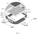
- each heat exchange plate 4041 may include a first arc-shaped portion 4043 and a second arc-shaped portion 4044, which are connected and both of which extend in a length direction of the heat exchange plate 4041, which refers to the left-right direction in Fig. 18 .
- a direction in which the first arc-shaped portion 4043 is recessed is opposite to a direction in which the second arc-shaped portion 4044 is recessed.
- the first arc-shaped portion 4043 is recessed towards the front of the heat exchange plate 4041
- the second arc-shaped portion 4044 is recessed toward the rear of the heat exchange plate 4041.
- first arc-shaped portion 4043 and the second arc-shaped portion 4044 of one of two adjacent ones of the heat exchange plates 4041 are arranged corresponding to the first arc-shaped portion 4043 and the second arc-shaped portion 4044 of the other heat exchange plate 4041, respectively.
- One battery cell 20 may be provided between the two first arc-shaped portions 4043 of the two adjacent heat exchange plates 4041, and one battery cell 20 may be provided between the two second arc-shaped portions 4044 of the two adjacent heat exchange plates 4041. In this way, it is possible to configure the heat exchange plate 4041 as a serpentine structure. After a battery cell 20 is installed between two adjacent heat exchange plates 4041, the heat exchange plate 4041 can limit the position of the battery cell 20, so that the position of the battery cell 20 can be more stable.
- the second heat exchange structure 404 may further include a first side plate 4045 and a second side plate 4046, and two ends of the heat exchange plate 4041 are connected to and in communication with the first side plate 4045 and the second side plate 4046, respectively.
- the first side plate 4045 and the second side plate 4046 can each define a refrigerant flow passage therein, so that the two ends of the heat exchange plate 4041 are in communication with the first side plate 4045 and the second side plate 4046, respectively.
- first side plate 4045 and the second side plate 4046 may be provided with a refrigerant inlet, and the other of the first side plate 4045 and the second side plate 4046 may be provided with a refrigerant outlet, so that the refrigerant can circulate inside the second heat exchange structure 404.
- the battery module 100 may further include end plates 4047, and two ends of the first side plate 4045 and two ends of the second side plate 4046 are connected to the end plates 4047; and/or the end plates 4047 are connected to the second battery cell supporting structure 400. Further, as shown in Fig. 18 , front ends of the first side plate 4045 and the second side plate 4046 are connected to the same end plate 4047, and rear ends of the first side plate 4045 and the second side plate 4046 are connected to the same end plate 4047, and the end plates 4047 are connected to the second battery cell supporting structure 400. In this way, it is possible to firmly assemble the structure of the battery module 100 and improve the structural stability of the battery module 100.
- the battery module 100 may further include a BMS (BATTERY MANAGEMENT SYSTEM) main board 50, which is connected to the low-voltage output plug-in 202 of the battery pack 1000 through a wire harness.
- the BMS main board 50 is arranged on the end plate 4047 or on the first side plate 4045 or on the second side plate 4046.
- the BMS main board 50 is provided on the end plate 4047, and it may be bonded and mounted on the end plate 4047, or be mounted on the end plate 4047 through a bolt, or be connected to the end plate 4047 in a snap fit manner.
- the BMS main board 50 By providing the BMS main board 50 on the end plate 4047, the BMS main board 50 can be integrated on the battery module 100. As a result, the battery module 100 and the BMS main board 50 have a compact overall structure. After the battery module 100 is installed in the housing 200, a situation in which the BMS main board 50 occupies space in another position of the battery pack 1000 can be avoided, and the space utilization rate in the battery pack 1000 can thus be improved.
- the second bottom supporting rib 402 and the second supporting body 401 jointly define a buffer space 4021 that is arranged corresponding to the battery cell 20 in a thickness direction of the second supporting body 401, which refers to an up-down direction in Fig. 13 .
- the buffer space 4021 can avoid the second bottom supporting rib 402, and the second bottom supporting rib 402 can deform and absorb energy, thereby making it possible to ensure the energy absorption effect of the second bottom supporting rib 402. In turn, the force received by the battery cell 20 can be reduced.
- the multiple buffer spaces 4021 and the multiple battery cells 20 are arranged in one-to-one correspondence, wherein the battery cell 20 may be a columnar battery cell 20.
- the battery cell 20 is a cylindrical battery cell 20, and one battery cell 20 is provided to correspond to one buffer space 4021. In this way, it is possible to increase an area for arranging the second bottom supporting rib 402. When the second bottom supporting rib 402 is stressed, it can transmit the force to the entire battery module 100, so as to make the force on the battery module 100 more uniform.
- the second bottom supporting rib 402 includes at least one supporting rib unit 4022, and each of the supporting rib units 4022 and the second supporting body 401 jointly define one of the buffer spaces 4021. In this way, it is possible to achieve the purpose of defining the buffer space 4021 and ensure the operating performance of the second bottom supporting rib 402.
- the second bottom supporting rib 402 includes a plurality of the supporting rib units 4022, two adjacent ones of which are connected. Further, any two adjacent ones of the supporting rib units 4022 are connected. Further, in a radial direction of the second battery cell supporting structure 400, the supporting rib unit 4022 has a polygonal section, such as a hexagonal section, and two adjacent supporting rib units 4022 have an overlapping area.
- the second supporting body 401 is provided with an avoidance hole 4023 penetrating the second supporting body 401 and provided corresponding to the buffer space 4021.
- the avoidance hole 4023 is in communication with the buffer space 4021, and the battery cell 20 is provided with an explosion-proof valve, which is arranged corresponding to the avoidance hole 4023.
- the explosion-proof valve of the battery cell 20 is arranged corresponding to the avoidance hole 4023, and when the gas in the battery cell 20 is discharged, the gas flows into the buffer space 4021 through the avoidance hole 4023 to achieve exhaust.
- the supporting rib unit 4022 is provided with an exhaust gap 4024 communicating with the buffer space 4021.
- the exhaust gap 4024 is an exhaust channel, and may be provided at an end of the supporting rib unit 4022 far from the second supporting body 401. After the gas in the battery cell 20 flows into the buffer space 4021 through the avoidance hole 4023, the gas in the buffer space 4021 can be discharged through the exhaust gap 4024.
- the second battery cell supporting structure 400 may further include a second upper supporting rib 403 provided on a surface of the second supporting body 401 close to the battery cell 20.
- the second upper supporting rib 403 and the second supporting body 401 jointly define an installation space 4031 for installing the battery cell 20, and the second upper supporting rib 403 is adapted to be sandwiched between two adjacent ones of the battery cells 20 of the battery module 100.
- the second upper supporting rib 403 extends in the same direction as the battery cell 20. Further, the second upper supporting rib 403 and the second supporting body 401 jointly define a plurality of installation spaces 4031.
- the installation space 4031 has a polygonal section, such as a hexagonal section.
- one installation space 4031 is provided facing one buffer space 4021.
- a second upper supporting rib 403 can be sandwiched between two adjacent battery cells 20. In this way, it is possible to allow the second battery cell supporting structure 400 to limit the position of the battery cell 20. Therefore, the battery cell 20 can be firmly installed in the second battery cell supporting structure 400, so that the position of the battery core 20 can be prevented from moving.
- the second upper supporting rib 403 is provided around the avoidance hole 4023, wherein the second upper supporting rib 403 is arranged outside the avoidance hole 4023 in the radial direction of the second battery cell supporting structure 400.
- the explosion-proof valve of the battery cell 20 can be easily provided to correspond to the avoidance hole 4023.
- the battery cell 20 can be bonded to the second battery cell supporting structure 400 via structural adhesive 15.
- the plurality of battery cells 20 of the battery module 100 are connected in series via a bus bar.
- the lower housing 201 is provided with a lower housing cross beam 2013, which is used to improve the modality and rigidity of the battery pack 1000. Further, the lower housing cross beam 2013 can be connected with a bottom wall and side walls of the lower housing 201, so that the structural strength of the lower housing 201 can be improved.
- housing 200 of the battery pack 1000 of the first embodiment has the same structure as the housing 200 of the battery pack 1000 of the second embodiment.
- the vehicle according to the embodiment of the present disclosure includes the vehicle body floor assembly of the above-mentioned embodiment.
- the housing 200 By configuring the housing 200 as the vehicle body floor, the housing 200 can replace the vehicle body floor.
- the vehicle does not need to have a separate vehicle body floor, which can improve the integration of the battery pack 1000 and the vehicle body, is conducive to the utilization of the height space of the vehicle, and can also reduce the weight of the vehicle.
Landscapes
- Engineering & Computer Science (AREA)
- Chemical & Material Sciences (AREA)
- Combustion & Propulsion (AREA)
- Transportation (AREA)
- Mechanical Engineering (AREA)
- Arrangement Or Mounting Of Propulsion Units For Vehicles (AREA)
- Battery Mounting, Suspending (AREA)
Abstract
Description
- This application claims a priority to
Chinese Patent Application No. 202111151169.3 titled "Vehicle body floor assembly for Vehicle and Vehicle", filed by SVOLT ENERGY TECHNOLOGY COMPANY LIMITED on September 29, 2021 - The present disclosure relates to the field of vehicles, in particular to a vehicle body floor assembly for a vehicle and a vehicle having the vehicle body floor assembly.
- As global petroleum resources are declining, the transformation of new energy vehicles to replace traditional fuel vehicles in the automotive industry has also accelerated. As the main energy carrier of new energy vehicles, a battery pack provides electrical energy for the entire vehicle.
- In the related art, the battery pack is installed as a separate component on a vehicle body floor. There is assembly clearance between the battery pack and the vehicle body floor, which results in low integration of the battery pack and the vehicle body, and which is not conducive to the utilization of the height space of the vehicle.
- The present invention aims to solve at least one of the technical problems existing in the prior art. To this end, a purpose of the present application is to propose a vehicle body floor assembly for a vehicle, in which a housing for a battery pack is configured as a vehicle body floor such that it can replace the vehicle body floor. As compared with the prior art, the vehicle does not need to have a separate vehicle body floor, which can improve the integration of the battery pack and the vehicle body, is conducive to the utilization of the height space of the vehicle and can also reduce the weight of the vehicle.
- The present application further proposes a vehicle.
- The vehicle body floor assembly for a vehicle according to the present disclosure includes a vehicle body mounting structure; a battery pack including a battery module and a housing in which the battery module is provided, wherein the housing is connected to the vehicle body mounting structure, and at least part of the structure of the housing is configured as a vehicle body floor for the vehicle.
- According to the vehicle body floor assembly for the vehicle of the present disclosure, by configuring the housing of the battery pack as the vehicle body floor, the housing can replace the vehicle body floor. As compared with the prior art, the vehicle does not need to have a separate vehicle body floor, which can improve the integration of the battery pack and the vehicle body, is conducive to the utilization of the height space of the vehicle and can also reduce the weight of the vehicle.
- In some embodiments of the present disclosure, the housing is provided with a vehicle body mounting portion, which is connected to the vehicle body mounting structure.
- In some embodiments of the present disclosure, the vehicle body mounting structure includes a left sill beam, a right sill beam, and a cross beam connected between the left sill beam and the right sill beam, the vehicle body mounting portion being connected to the cross beam.
- In some embodiments of the present disclosure, the housing includes an upper housing and a lower housing jointly defining an installation cavity for installing the battery module, wherein the upper housing is provided with the vehicle body mounting portion and is configured as the vehicle body floor.
- In some embodiments of the present disclosure, a circumferential edge of the housing is provided with a connecting edge, which is connected to the left sill beam and/or the right sill beam; the vehicle body mounting structure further includes an end beam connected between the left and right sill beam, and the connecting edge is connected to the end beam.
- In some embodiments of the present disclosure, the housing is provided with a seat installation portion for installing a seat of the vehicle.
- In some embodiments of the present disclosure, the housing is provided with a high-voltage output plug-in configured to be connected to an output pole of the battery module, and with a low-voltage output plug-in configured to connect and communicate with a BMS main board of the battery pack; the high-voltage output plug-in and/or the low-voltage output plug-in are provided under a rear seat of the vehicle, and the high-voltage output plug-in and the low-voltage output plug-in are both configured to be connected to an electrical component of the vehicle.
- In some embodiments of the present disclosure, the battery module is bonded to the housing.
- In some embodiments of the present disclosure, the battery pack further includes a first heat exchange structure provided in the housing and located outside the battery module, and configured to exchange heat with the battery module.
- In some embodiments of the present disclosure, the battery module includes a battery cell unit; a side frame provided around the battery cell unit; a first battery cell supporting structure, which is supported between the battery cell and the housing and which includes a first supporting body and a first bottom supporting rib, wherein the first supporting body is configured to support the battery cell unit and is provided with an avoidance groove penetrating the first supporting body, and the first bottom supporting rib is connected to the first supporting body and is located on a side of the first supporting body far from the battery cell unit, and the first bottom supporting rib corresponds to the avoidance groove in a thickness direction of the first supporting body.
- In some embodiments of the present disclosure, the battery module further includes a BMS main board provided on the side frame.
- In some embodiments of the present disclosure, the battery module includes a columnar battery cell; a second heat exchange structure, wherein the battery cell is sandwiched in the second heat exchange structure, and the second heat exchange structure is configured to exchange heat with the battery cell; a second battery cell supporting structure, which is supported between the battery cell and the housing and which includes a second supporting body and a second bottom supporting rib, wherein the second supporting body is configured to support the battery cell, and the second bottom supporting rib is connected to the second supporting body and is located on a side of the second supporting body far from the battery cell.
- In some embodiments of the present disclosure, the second heat exchange structure includes multiple heat exchange plates, which are sequentially spaced apart in a length direction of the battery module to form a sandwiching space between two adjacent ones of the heat exchange plates, in which the battery cell is sandwiched;
Each of the heat exchange plates includes first and second arc-shaped portions, which are connected and both of which extend in a length direction of the heat exchange plate. In the length direction of the battery module, a direction in which the first arc-shaped portion is recessed is opposite to a direction in which the second arc-shaped portion is recessed, and the first and second arc-shaped portions of one of two adjacent ones of the heat exchange plates are arranged corresponding to the first and second arc-shaped portions of the other heat exchange plate, respectively. - In some embodiments of the present disclosure, the second heat exchange structure further includes first and second side plates, and two ends of the heat exchange plate are connected to and in communication with the first and second side plates, respectively;
- The battery module further includes end plates, and two ends of the first side plate and two ends of the second side plate are connected with the end plates; and/or the end plates are connected to the second battery cell supporting structure;
- The battery module further includes a BMS main board provided on the end plate, or on the first side plate, or on the second side plate.
- In some embodiments of the present disclosure, the second bottom supporting rib and the second supporting body jointly define buffer spaces, which corresponds to the battery cell in a thickness direction of the second supporting body;
- The second bottom supporting rib includes at least one supporting rib unit, and each of the supporting rib units and the second supporting body jointly define one of the buffer spaces;
- The second bottom supporting rib includes a plurality of the supporting rib units, two adjacent ones of which are connected;
- The second supporting body is provided with an avoidance hole penetrating the second supporting body, wherein the avoidance hole is provided corresponding to the buffer space, and an explosion-proof valve for the battery cell is provided corresponding to the avoidance hole;
- The supporting rib unit is provided with an exhaust gap communicating with the buffer space;
- The second battery cell supporting structure further includes a second upper supporting rib provided on a surface of the second supporting body close to the battery cell, the second upper supporting rib and the second supporting body jointly define an installation space for installing the battery cell, and the second upper supporting rib is adapted to be sandwiched between two adjacent ones of the battery cells.
- The vehicle according to the present disclosure includes the vehicle body floor assembly for the vehicle as described above.
- According to the vehicle of the present disclosure, by configuring the housing of the battery pack as the vehicle body floor, the housing can replace the vehicle body floor. As compared with the prior art, the vehicle does not need to have a separate vehicle body floor, which can improve the integration of the battery pack and the vehicle body, is conducive to the utilization of the height space of the vehicle and can also reduce the weight of the vehicle.
- Some of additional aspects and advantages of the present invention will be provided in the following description, while others will become apparent from the following description, or be learned through the practice of the present invention.
-
-
Fig. 1 is an exploded view of a battery pack according to a first embodiment of embodiments of the present disclosure; -
Fig.2 is an exploded view of battery cells, structural adhesive and a first battery cell supporting structure according to an embodiment of the present disclosure; -
Fig.3 is a schematic diagram of the first battery cell supporting structure according to the embodiment of the present invention; -
Fig.4 is an enlarged view of part A inFig.3 ; -
Fig. 5 is a schematic view from another perspective of the first battery cell supporting structure according to the embodiment of the present disclosure; -
Fig.6 is an enlarged view of part B inFig.5 ; -
Fig.7 is an enlarged view of part C inFig. 1 ; -
Fig. 8 is an enlarged view of part D inFig.1 ; -
Fig.9 is an enlarged view of part E inFig. 1 ; -
Fig. 10 is an enlarged view of part F inFig.1 ; -
Fig. 11 is a schematic diagram of the assembly of the battery pack according to the first embodiment of the embodiments of the present disclosure, seats and a vehicle body mounting structure; -
Fig. 12 is an exploded view of a battery pack, seats and a vehicle body mounting structure according to an embodiment of the present disclosure; -
Fig. 13 is an exploded view of a battery pack according to a second embodiment of the embodiments of the present disclosure; -
Fig. 14 is a schematic diagram of a second battery cell supporting structure according to an embodiment of the present disclosure; -
Fig. 15 is a partial enlarged view of the second battery cell supporting structure inFig. 14 ; -
Fig. 16 is a schematic view from another perspective of the second battery cell supporting structure according to the embodiment of the present disclosure; -
Fig. 17 is a partial enlarged view of the second battery cell supporting structure inFig. 16 ; -
Fig. 18 is an enlarged view of part G inFig. 13 . - The embodiments of the present disclosure are described in detail below. Examples of the embodiments are shown in the accompanying drawings, in which the same or similar reference numerals indicate the same or similar elements or elements having the same or similar functions. The embodiments described below with reference to the drawings are exemplary, and are only intended to explain the present invention, and should not be construed as limiting the present invention.
- A vehicle body floor assembly for a vehicle according to an embodiment of the present disclosure will be described below with reference to
Figs. 1-18 . - As shown in
Figs. 1 to 18 , the vehicle body floor assembly according to the embodiment of the present disclosure includes a vehiclebody mounting structure 300 and abattery pack 1000. Thebattery pack 1000 includes abattery module 100 and ahousing 200 in which thebattery module 100 is provided. Thehousing 200 is connected to the vehiclebody mounting structure 300, and at least part of the structure of thehousing 200 is configured as a vehicle body floor for the vehicle. Further, part of the structure of thehousing 200 is configured as the vehicle body floor for the vehicle. - The vehicle
body mounting structure 300 may be a chassis structure of the vehicle, and may include sill beams and other structures. By connecting thehousing 200 to the vehiclebody mounting structure 300, thebattery pack 1000 can be mounted on the vehiclebody mounting structure 300. Moreover, by configuring thehousing 200 as the vehicle body floor, the arrangement of a vehicle body floor can be omitted. That is, the vehicle does not need to have a separate vehicle body floor, which can reduce the weight of the vehicle. At the same time, it can improve the integration of the battery pack and the vehicle body, and is conducive to the utilization of the height space of the vehicle. - Therefore, by configuring the
housing 200 as the vehicle body floor, thehousing 200 can replace the vehicle body floor. As compared with the prior art, the vehicle does not need to have a separate vehicle body floor, which can improve the integration of thebattery pack 1000 and the vehicle body, is conducive to the utilization of the height space of the vehicle, and can also reduce the weight of the vehicle. - In some embodiments of the present disclosure, as shown in
Figs. 1 and13 , thehousing 200 is provided with a vehiclebody mounting portion 204, which is connected to the vehiclebody mounting structure 300. By providing the vehiclebody mounting portion 204, it is convenient to install thehousing 200 in the vehiclebody mounting structure 300, which can improve the installation efficiency of thebattery pack 1000. - In some embodiments of the present disclosure, as shown in
Fig. 12 , the vehiclebody mounting structure 300 includes aleft sill beam 303, aright sill beam 304, and across beam 305 connected between theleft sill beam 303 and theright sill beam 304. One end of thecross beam 305 is welded to theleft sill beam 303, and the other end of thecross beam 305 is welded to theright sill beam 304, and the vehiclebody mounting portion 204 is connected to thecross beam 305. Further, the vehiclebody mounting portion 204 is bolted to thecross beam 305. In this way, it is possible to reliably install thebattery pack 1000 on the vehiclebody mounting structure 300 and also removably install thebattery pack 1000 on the vehiclebody mounting structure 300. - In some embodiments of the present disclosure, as shown in
Figs. 1 and13 , thehousing 200 includes anupper housing 203 and alower housing 201 jointly defining aninstallation cavity 205 for installing thebattery module 100, wherein theupper housing 203 is provided with the vehiclebody mounting portion 204, and is configured as the vehicle body floor. - In some embodiments of the present disclosure, as shown in
Figs. 1 and13 , a circumferential edge of thehousing 200 is provided with a connecting edge, which is connected to theleft sill beam 303 and/or theright sill beam 304. Further, the vehiclebody mounting structure 300 further includes anend beam 306, which is connected between theleft sill beam 303 and theright sill beam 304 and which is welded to both theleft sill beam 303 and theright sill beam 304, and the connecting edge is connected to theend beam 306. In this way, thebattery pack 1000 can be more reliably mounted on the vehiclebody mounting structure 300. - In some embodiments of the present disclosure, as shown in
Figs. 1 and13 , thehousing 200 is provided with aseat installation portion 206 for installing aseat 301 of the vehicle. Further, in a height direction of the vehicle, theseat installation portion 206 can be provided corresponding to afront seat 301 of the vehicle, and can be used to install thefront seat 301 of the vehicle. In this way, it is possible to achieve the purpose of installing theseat 301 with thebattery pack 1000 and also allow theseat 301 to be reliably installed on thehousing 200 of thebattery pack 1000. - In some embodiments of the present disclosure, as shown in
Figs. 1 and9 , thehousing 200 is provided with a high-voltage output plug-in 207 configured to be connected to anoutput pole 21 of thebattery module 100, and with a low-voltage output plug-in 202 configured to connect and communicate with a BMSmain board 50 of thebattery pack 1000. In this way, thebattery pack 1000 can output high-voltage power through the high-voltage output plug-in 207, and the BMSmain board 50 can also communicate with the outside through the low-voltage output plug-in 202. - Further, as shown in
Fig. 12 , the high-voltage output plug-in 207 and/or the low-voltage output plug-in 202 are provided under arear seat 301 of the vehicle. Preferably, the high-voltage output plug-in 207 and the low-voltage output plug-in 202 are both provided under therear seat 301 of the vehicle. By providing anelectrical component 302 between therear seat 301 of the vehicle and thebattery pack 1000, the maintenance of theelectrical component 302 can be facilitated. Moreover, the high-voltage output plug-in 207 and the low-voltage output plug-in 202 are both configured to be connected to theelectrical component 302 of the vehicle. It should be noted that theelectrical component 302 is provided outside thebattery pack 1000, and may include a power distribution unit for the vehicle and a power distribution box and other structural parts of thebattery pack 1000. The high-voltage output plug-in 207 can be connected to the power distribution unit, and the low-voltage output plug-in 202 can be connected to the power distribution box. By providing the power distribution box outside thebattery pack 1000, an internal space of thebattery pack 1000 can be saved, and this can increase the energy density of thebattery pack 1000. - In some embodiments of the present disclosure, as shown in
Figs. 1 and13 , thebattery module 100 is bonded to thehousing 200. Further, thebattery module 100 is bonded to an inner surface of thehousing 200 viastructural adhesive 15. - As shown in
Figs 1 to 12 , thebattery pack 1000 according to a first embodiment of the present disclosure includes ahousing 200, abattery module 100 provided in thehousing 200, and a firstheat exchange structure 60 provided in thehousing 200 and located outside thebattery module 100 and configured to exchange heat with thebattery module 100. Further, the firstheat exchange structure 60 may be provided as a heat exchange plate that exchanges heat with thebattery module 100 to keep thebattery pack 1000 at a suitable operating temperature. - As shown in
Figs. 1 to 12 , thehousing 200 includes anupper housing 203 and alower housing 201. Theupper housing 203 is connected to thelower housing 201, and they jointly define aninstallation cavity 205 for installing thebattery module 100 of thebattery pack 1000. Thebattery module 100 is installed in theinstallation cavity 205. Thehousing 200 is provided with a vehiclebody mounting portion 204, and in particular, theupper housing 203 is provided with the vehiclebody mounting portion 204 configured to be connected to the vehiclebody mounting structure 300 of the vehicle. Thehousing 200 is configured as the vehicle body floor of the vehicle, and in particular, theupper housing 203 is configured as the vehicle body floor of the vehicle. - It should be noted that the vehicle
body mounting structure 300 may be the chassis structure of the vehicle, the vehiclebody mounting structure 300 may include sill beams and other structures, and the vehiclebody mounting portion 204 may be provided as a bolt and may be connected to the vehiclebody mounting structure 300 through the bolt, but the present invention is not limited thereto. The vehiclebody mounting portion 204 may be connected in a snap fit manner or welded to the vehiclebody mounting structure 300. By connecting the vehiclebody mounting portion 204 to the vehiclebody mounting structure 300, thebattery pack 1000 can be mounted on the vehiclebody mounting structure 300. Moreover, by configuring theupper housing 203 as the vehicle body floor, the arrangement of a vehicle body floor can be omitted. That is, the vehicle does not need to have a separate vehicle body floor, which can reduce the weight of the vehicle. At the same time, it can improve the integration of the battery pack and the vehicle body, and is conducive to the utilization of the height space of the vehicle. - Therefore, by configuring the
upper housing 203 as the vehicle body floor, theupper housing 203 can replace the vehicle body floor. As compared with the prior art, the vehicle does not need to have a separate vehicle body floor, which can improve the integration of thebattery pack 1000 and the vehicle body, is conducive to the utilization of the height space of the vehicle, and can also reduce the weight of the vehicle. - In some embodiments of the present disclosure, the vehicle
body mounting portion 204 is bolted to the vehiclebody mounting structure 300, wherein there may be a plurality of the vehiclebody mounting portions 204, all of which may be provided as bolts. The bolts may be integrally formed with theupper housing 203. By the threaded connection between the bolts and the vehiclebody mounting structure 300, thebattery pack 1000 can be reliably assembled on the vehiclebody mounting structure 300, which prevents thebattery pack 1000 from falling off the vehiclebody mounting structure 300. Furthermore, by bolting the vehiclebody mounting portion 204 to the vehiclebody mounting structure 300, it is convenient to remove thebattery pack 1000 from the vehiclebody mounting structure 300 and install thebattery pack 1000 on the vehiclebody mounting structure 300. - In some embodiments of the present disclosure, as shown in
Figs. 1 and8 , theupper housing 203 is provided with aseat installation portion 206 for installing aseat 301 of the vehicle. Further, in the height direction of the vehicle, theseat installation portion 206 can be provided corresponding to afront seat 301 of the vehicle, and can be used to install thefront seat 301 of the vehicle. In this way, it is possible to achieve the purpose of installing theseat 301 using thebattery pack 1000 and also allow theseat 301 to be reliably installed on thehousing 200 of thebattery pack 1000. - In some embodiments of the present disclosure, as shown in
Fig. 8 , theseat installation portion 206 may include aseat mounting bracket 2061, inside which anut 2062 is provided to be connected to theseat 301. Theseat mounting bracket 2061 is mounted on theupper housing 203, and theseat 301 may be provided with a bolt, so that theseat 301 can be reliably mounted on theseat installation portion 206 by connecting the bolt and thenut 2062. However, the present invention is not limited to this, and theseat installation portion 206 and theseat 301 may be connected in another way. For example, theseat installation portion 206 and theseat 301 are connected in a snap fit manner, or they may be welded together. - In some embodiments of the present disclosure, as shown in
Fig. 8 , theseat mounting bracket 2061 may include a mountingbody 2063 and a mountingflange 2064 connected to theupper housing 203, wherein thenut 2062 is provided on the mountingbody 2063, and the mountingbody 2063 is spaced apart from theupper housing 203. By configuring the mountingbody 2063 to be spaced apart from theupper housing 203, an avoidance space can be formed between the mountingbody 2063 and theupper housing 203. When thenut 2062 is connected to the bolt, the avoidance space can avoid the bolt, thereby making it possible to ensure reliable installation of theseat 301 on thehousing 200. In addition, an area of contact between theseat mounting bracket 2061 and theupper housing 203 can be increased, and theseat mounting bracket 2061 can be stably installed on theupper housing 203, through connecting the plate-like mounting flange 2064 to theupper housing 203. - In some embodiments of the present disclosure, as shown in
Figs. 1 and9 , theupper housing 203 is provided with a high-voltage output plug-in 207 configured to be connected to anoutput pole 21 of thebattery module 100, and with a low-voltage output plug-in 202 configured to connect and communicate with a BMSmain board 50 of thebattery pack 1000. In this way, thebattery pack 1000 can output high-voltage power through the high-voltage output plug-in 207, and the BMSmain board 50 can also communicate with the outside through the low-voltage output plug-in 202. - Further, as shown in
Fig. 12 , the high-voltage output plug-in 207 and/or the low-voltage output plug-in 202 are provided under therear seat 301 of the vehicle. Preferably, the high-voltage output plug-in 207 and the low-voltage output plug-in 202 are both provided under therear seat 301 of the vehicle. By providing anelectrical component 302 between therear seat 301 of the vehicle and thebattery pack 1000, the repair of theelectrical component 302 can be facilitated. Moreover, the high-voltage output plug-in 207 and the low-voltage output plug-in 202 are both configured to be connected to theelectrical component 302 of the vehicle. It should be noted that theelectrical component 302 is provided outside thebattery pack 1000, and may include a power distribution unit for the vehicle and a power distribution box and other structural parts of thebattery pack 1000. The high-voltage output plug-in 207 can be connected to the power distribution unit, and the low-voltage output plug-in 202 can be connected to the power distribution box. By providing the power distribution box outside thebattery pack 1000, an internal space of thebattery pack 1000 can be saved, and this can increase the energy density of thebattery pack 1000. - In some embodiments of the present disclosure, as shown in
Figs. 1 and12 , a circumferential edge of theupper housing 203 is provided with an upper connectingedge 2031, and a circumferential edge of thelower housing 201 is provided with a lower connectingedge 2011. The upper and lower connectingedges installation cavity 205 and prevent dust and other debris from entering theinstallation cavity 205. - Further, as shown in
Figs. 1 and12 , the upper connectingedge 2031 is provided with an upper connectinghole 2032, and the lower connectingedge 2011 is provided with a lower connectinghole 2012 corresponding to the upper connectinghole 2032. A fastener (such as a bolt) passes through the upper connectinghole 2032 and the lower connectinghole 2012 simultaneously and is used to be connected to the vehiclebody mounting structure 300. The fastener can pass through the lower connectingedge 2011 and the upper connectinghole 2032 in sequence before being connected to the vehiclebody mounting structure 300. In this way, it is possible to firmly install thebattery pack 1000 on the vehiclebody mounting structure 300 and prevent thebattery pack 1000 from falling off. - In some embodiments of the present disclosure, the
housing 200 may be provided with a repair hole provided corresponding to the BMSmain board 50, and with a repair cover configured to open or close the repair hole, making it easy to repair the BMSmain board 50. - In some embodiments of the present disclosure, as shown in
Fig. 12 , theupper housing 203 is provided with agasket 2033 provided corresponding to the upper connectinghole 2032 and configured for position limitation. - In some embodiments of the present disclosure, the
battery module 100 is bonded to thehousing 200. Further, thebattery module 100 may be bonded to thelower housing 201 viastructural adhesive 15, thereby fixing thebattery module 100 inside thehousing 200. - In some embodiments of the present disclosure, a first
heat exchange structure 60 is provided between thebattery module 100 and thehousing 200, and is bonded to both thebattery module 100 and thehousing 200. Further, the bonding between the firstheat exchange structure 60 and thebattery module 100, as well as the bonding between the firstheat exchange structure 60 and thehousing 200 can be carried out throughstructural adhesive 15. The firstheat exchange structure 60 can be provided on theupper housing 203 and thebattery module 100, thereby firmly installing the firstheat exchange structure 60 and thebattery module 100 inside thehousing 200. - In some embodiments of the present disclosure, as shown in
FIG. 1 , thelower housing 201 is provided with a lowerhousing cross beam 2013, which is configured to improve the modality and rigidity of thebattery pack 1000. Further, the lowerhousing cross beam 2013 can be connected to a bottom wall and side walls of thelower housing 201, so that the structural strength of thelower housing 201 can be improved. - As shown in
Fig. 1 , thebattery pack 1000 according to the embodiment of the present disclosure includes thehousing 200 of the above-mentioned embodiment. By configuring theupper housing 203 as the vehicle body floor, theupper housing 203 can replace the vehicle body floor. As compared with the prior art, the vehicle does not need to have a separate vehicle body floor, which can improve the integration of thebattery pack 1000 and the vehicle body, is conducive to the utilization of the height space of the vehicle, and can also reduce the weight of the vehicle. - The
battery module 100 according to an embodiment of the present disclosure will be described below with reference toFigs. 1 to 6 . - As shown in
Figs. 1 to 6 , thebattery module 100 according to the embodiment of the present disclosure includes abattery cell unit 30, aside frame 40 and a first batterycell supporting structure 10. Theside frame 40 is provided around thebattery cell unit 30, and further, theside frame 40 is configured as a closed-loop structure, is provided around side surfaces of thebattery cell unit 30, and can be bonded to thebattery cell unit 30. - As shown in
Figs. 1 to 6 , the first batterycell supporting structure 10 is supported between thebattery cell 20 and thehousing 200, and includes a first supportingbody 11 and a firstbottom supporting rib 12. The first supportingbody 11 is configured to support thebattery cell unit 30. Further, thebattery cell unit 30 is provided on an upper surface of the first supportingbody 11, and the first supportingbody 11 is provided with anavoidance groove 111 penetrating the first supportingbody 11. Further, theavoidance groove 111 penetrates the first supportingbody 11 in a thickness direction of the first supportingbody 11. The firstbottom supporting rib 12 is connected to the first supportingbody 11 and is located on a side of the first supportingbody 11 far from thebattery cell unit 30. For example, thebattery cell unit 30 is provided on the upper surface of the first supportingbody 11, and the firstbottom supporting rib 12 is arranged below the first supportingbody 11. The firstbottom supporting rib 12 and theavoidance groove 111 are provided corresponding to each other in the thickness direction of the first supportingbody 11. Preferably, the firstbottom supporting rib 12 is provided facing theavoidance groove 111 in the thickness direction of the first supportingbody 11. - The
battery module 100 is provided with a first batterycell supporting structure 10. In this case, the first batterycell supporting structure 10 belongs to the structure of thebattery module 100, but the present invention is not limited to this. The first batterycell supporting structure 10 may be provided as a separate part. Preferably, the first batterycell supporting structure 10 belongs to the structure of thebattery module 100. When the first batterycell supporting structure 10 supports theunit 30, there is clearance between the firstbottom supporting rib 12 and thebattery cell unit 30, that is, thebattery cell unit 30 is spaced apart from the firstbottom supporting rib 12. When the bottom of the first batterycell supporting structure 10 is subjected to an impact, the first batterycell supporting structure 10 plays a buffering role and can absorb the impact force. As a result, the impact force received by thebattery cell unit 30 can be reduced, making it possible to improve the safety of using thebattery module 100, and also extend the service life of thebattery module 100. - Further, the
battery module 100 can be installed inside thehousing 200 of thebattery pack 1000. Of course, thebattery module 100 can be installed on other parts. This invention is described by taking a case where thebattery module 100 is installed inside thehousing 200 of thebattery pack 1000 as an example. Thebattery module 100 is installed inside thehousing 200 of thebattery pack 1000, and the first batterycell supporting structure 10 is supported below thebattery cell unit 30. Further, the first batterycell supporting structure 10 is supported between thebattery cell unit 30 and the housing 200 (the lower housing 201). When the bottom of the housing 200 (the lower housing 201) of thebattery pack 1000 is subjected to an impact, since there is clearance between the firstbottom supporting rib 12 and thebattery cell unit 30, the impact force will not be directly transmitted to thebattery cell unit 30 through the firstbottom supporting rib 12, and the first batterycell supporting structure 10 can absorb the impact force. Since the first batterycell supporting structure 10 can deform and absorb energy, the impact force received by thebattery cell unit 30 can be reduced, making it possible to improve the safety of using thebattery module 100 and thebattery pack 1000, and also extend the service life of thebattery module 100 and thebattery pack 1000. - Therefore, through providing the first
bottom supporting rib 12 corresponding to theavoidance groove 111, the first batterycell supporting structure 10 is installed inside thehousing 200 of thebattery pack 1000 to support thebattery cell unit 30. When the bottom of thehousing 200 of thebattery pack 1000 is subjected to an impact, the first batterycell supporting structure 10 plays a buffering role and can absorb the impact force. As a result, the impact force received by thebattery cell unit 30 can be reduced, making it possible to improve the safety of using thebattery module 100 and thebattery pack 1000, and also extend the service life of thebattery module 100 and thebattery pack 1000. - In some embodiments of the present disclosure, as shown in
Fig. 1 , thehousing 200 includes alower housing 201 and anupper housing 203, which are connected in a sealed manner, and between which thebattery module 100 is installed. - In some embodiments of the present disclosure, as shown in
Fig. 1 , thebattery pack 1000 may further include a BMS (BATTERY MANAGEMENT SYSTEM)main board 50, which is connected to the low-voltage output plug-in 202 of thebattery pack 1000 through a wire harness. The BMSmain board 50 is provided on theside frame 40, and further, the BMSmain board 50 may be bonded and mounted on theside frame 40, or be mounted on theside frame 40 through a bolt, or be connected to theside frame 40 in a snap fit manner. By providing the BMSmain board 50 on theside frame 40, the BMSmain board 50 can be integrated on thebattery module 100. As a result, thebattery module 100 and the BMSmain board 50 have a compact overall structure. After thebattery module 100 is installed in thehousing 200, a situation in which the BMSmain board 50 occupies space in another position of thebattery pack 1000 can be avoided, and the space utilization rate in thebattery pack 1000 can thus be improved. - In some embodiments of the present disclosure, as shown in
Fig. 1 , theside frame 40 may include aleft side frame 41, aright side frame 42, afront side frame 43 and a rear side frame 44, all of which can be constructed as plate-like structures, and which are connected end to end in sequence. Theleft side frame 41 is located on a left side of thebattery cell unit 30, theright side frame 42 is located on a right side of thebattery cell unit 30, thefront side frame 43 is located on a front side of thebattery cell unit 30, and the rear side frame 44 is located on a back side of thebattery cell unit 30. The BMSmain board 50 can be mounted on thefront side frame 43. In this way, it is possible to make the structure of theside frame 40 simple and make it easy to assemble theside frame 40 and thebattery cell unit 30 together. - In some embodiments of the present disclosure, as shown in
Figs. 1 and2 , thebattery cell unit 30 may be bonded to the first batterycell supporting structure 10. Further, thebattery cell unit 30 may be bonded to the first supportingbody 11 of the first batterycell supporting structure 10 viastructural adhesive 15. In this way, thebattery cell 30 can be reliably installed on the first batterycell supporting structure 10, preventing thebattery cell unit 30 from moving. - In some embodiments of the present disclosure, as shown in
Figs. 1 and2 , thebattery cell unit 30 may include a plurality ofbattery cells 20, which may be sequentially arranged in a thickness direction of thebattery cell 20, and which extend in the same direction. In this way, it is possible to allow the plurality ofbattery cells 20 to be arranged on the first batterycell supporting structure 10 in a regular manner, making it possible to installmore battery cells 20 on the first batterycell supporting structure 10. - In some embodiments of the present disclosure, as shown in
Fig. 6 , in the thickness direction of the first supportingbody 11, the firstbottom supporting rib 12 is spaced apart from theavoidance groove 111. In this way, it is possible to provide sufficient clearance between the firstbottom supporting rib 12 and thebattery cell 20 when the firstbattery support structure 10 supports thebattery cell 20. When the firstbottom supporting rib 12 of the first batterycell supporting structure 10 is subjected to an impact, the transmission of the impact force by the firstbottom supporting rib 12 to thebattery cell 20 can be effectively avoided, making it possible to further reduce the impact force received by thebattery cell 20. As a result, the safety of using thebattery module 100 and thebattery pack 1000 can be further improved, and the service life of thebattery module 100 and thebattery pack 1000 can also be extended. - In some embodiments of the present disclosure, as shown in
Fig. 6 , the firstbottom supporting rib 12 may include a first lower supportingrib 121, which extends in the same direction as theavoidance groove 111, and which corresponds to theavoidance groove 111 in the thickness direction of the first supportingbody 11 and is spaced apart from theavoidance groove 111. Further, the first batterycell supporting structure 10 may further include aside panel 14, which is sleeved on the circumferential edge of the first supportingbody 11. Further, the circumferential edge of the first supportingbody 11 is connected to a middle position of theside panel 14. Theside panel 14 can be integrally formed with the first supportingbody 11, and at least one end of the first lower supportingrib 121 is connected to theside panel 14. The first lower supportingrib 121 and theavoidance groove 111 may both extend in the length direction of the first batterycell supporting structure 10. Of course, the first lower supportingrib 121 and theavoidance groove 111 may both extend in a width direction of the first batterycell supporting structure 10. Preferably, the first lower supportingrib 121 and theavoidance groove 111 both extend in the length direction of the first batterycell supporting structure 10. The length direction of the first batterycell supporting structure 10 refers to a front-rear direction inFig. 5 . The extension direction of the first lower supportingrib 121 is perpendicular to the extension direction of thebattery cell 20. In this way, it is possible to ensure that the first lower supportingrib 121 is provided facing theavoidance groove 111 and prevent the impact force from being transmitted to thebattery cell 20 through the first lower supportingrib 121. - In some embodiments of the present disclosure, as shown in
Fig. 6 , the firstbottom supporting rib 12 may further include a second lower supportingrib 122, which is provided on a surface of the first supportingbody 11 far from thebattery cell unit 30, and which is arranged to cross the first lower supportingrib 121, wherein at least one end of the second lower supportingrib 122 is connected to theside panel 14, and the second lower supportingrib 122 may be integrally formed with the first supportingbody 11. Through configuring the second lower supportingrib 122 and the first lower supportingrib 121 crossing each other, the second lower supportingrib 122 can support the first lower supportingrib 121, and can improve the structural strength of the second lower supportingrib 122. Therefore, the deformation and energy absorption capacity of the second lower supportingrib 122 can be improved, and the impact force received by thebattery cell 20 can be further reduced. - In some embodiments of the present disclosure, as shown in
Fig. 6 , the first lower supportingrib 121 and the second lower supportingrib 122 are provided perpendicular to each other. For example, the first lower supportingrib 121 is provided to extend in the length direction of the first batterycell supporting structure 10, and the second lower supportingrib 122 is provided to extend in the width direction of the first batterycell supporting structure 10. The length direction of the first batterycell supporting structure 10 refers to a front-rear direction inFig. 5 , and the width direction of the first batterycell supporting structure 10 refers to a left-right direction inFig.5 . The second lower supportingrib 122 extends in the same direction as thebattery cell 20. Further, the first lower supportingrib 121 and the second lower supportingrib 122 are both configured as plate-like structures, and are integrally formed. In this way, the second lower supportingrib 122 can better support the first lower supportingrib 121, which can further improve the deformation and energy absorption capacity of the second lower supportingrib 122, which, in turn, can further reduce the impact force received by thebattery cell 20. - In some embodiments of the present disclosure, as shown in
Fig.6 , the second lower supportingrib 122 is provided with afirst avoidance gap 123 communicating with theavoidance groove 111. In the thickness direction of the first supportingbody 11, thefirst avoidance gap 123 is provided corresponding to theavoidance groove 111 and the first lower supportingrib 121. Preferably, thefirst avoidance gap 123 is provided facing theavoidance groove 111 and the first lower supportingrib 121. An end of the second lower supportingrib 122 close to the first supportingbody 11 is provided with thefirst avoidance gap 123. In this way, it is possible to ensure that there is sufficient clearance between the first lower supportingrib 121 and thebattery cell 20, which can increase the energy absorption effect of the first batterycell supporting structure 10, thereby making it possible to further prevent the impact force from acting on thebattery cell 20. - In some embodiments of the present disclosure, as shown in
Figs. 3 and4 , the first batterycell supporting structure 10 may further include a firstupper supporting rib 13, which is provided on a surface of the first supportingbody 11 close to thebattery cell unit 30, which is provided on a surface of the first supportingbody 11 close to thebattery cell unit 30, and which is provided between two adjacent ones of thebattery cells 20. Further, the firstupper supporting rib 13 is adapted to be sandwiched between two adjacent ones of thebattery cells 20 of thebattery module 100. At least one end of the firstupper supporting rib 13 is connected to theside panel 14, and the firstupper supporting rib 13 extends in the same direction as thebattery cell 20. Thebattery module 100 may include a plurality of thebattery cells 20, each of which may be arranged in a rectangular shape and which may be arranged in sequence in the length direction of the first batterycell supporting structure 10. There may be a plurality of the firstupper supporting ribs 13 spaced apart in sequence in the arrangement direction of thebattery cells 20, that is, the plurality of first upper supportingribs 13 are spaced apart in sequence in the length direction of the first batterycell supporting structure 10, thereby separating the first batterycell supporting structure 10 into a plurality of batterycell placement slots 132, which are in communication with theavoidance groove 111. In each batterycell placement slot 132, onebattery cell 20 is installed, and one of the firstupper supporting ribs 13 may be provided between twoadjacent battery cells 20. In this way, the first batterycell supporting structure 10 can limit thebattery cell 20, making it possible to firmly install thebattery cell 20 on the first batterycell supporting structure 10, thereby preventing the position of thebattery cell 20 from moving. - Further, the first
upper supporting rib 13 may be configured as a plate-like structure, and the thickness of each of the firstupper supporting ribs 13 is smaller than the clearance between twoadjacent battery cells 20, and a spacing distance between two adjacent ones of the firstupper supporting ribs 13 is greater than the thickness of thebattery cell 20. In this way, it is possible to ensure that thebattery cell 20 can be installed in the batterycell placement slot 132. - In some embodiments of the present disclosure, as shown in
Fig.6 , the firstupper supporting rib 13 is arranged opposite to the second lower supportingrib 122 in the thickness direction of the first supportingbody 11. Preferably, the firstupper supporting rib 13 is provided facing the second lower supportingrib 122 in the thickness direction of the first supportingbody 11, and is provided with asecond avoidance gap 131 arranged corresponding to theavoidance groove 111, wherein an end of the firstupper supporting rib 13 facing the first supportingbody 11 is provided with thesecond avoidance gap 131 arranged facing theavoidance groove 111. In this way, an area of contact between the firstupper supporting rib 13 and thebattery cell 20 can be reduced, and the transmission of force from the firstupper supporting rib 13 to thebattery cell 20 can be reduced. As a result, the force received by thebattery cell 20 can be reduced, making it possible to extend the service life of thebattery cell 20, and thus to improve the energy absorption capacity of the first batterycell supporting structure 10. - As shown in
Figs. 7-9 and13-18 , thebattery pack 1000 according to a second embodiment of the present disclosure includes ahousing 200 and abattery module 100 provided in thehousing 200. - As shown in
Figs. 7-9 and13-18 , thehousing 200 includes anupper housing 203 and alower housing 201. Theupper housing 203 is connected to thelower housing 201, and they jointly define aninstallation cavity 205 for installing thebattery module 100 of thebattery pack 1000. Thebattery module 100 is installed in theinstallation cavity 205. Thehousing 200 is provided with a vehiclebody mounting portion 204, and in particular, theupper housing 203 is provided with the vehiclebody mounting portion 204 configured to be connected to the vehiclebody mounting structure 300. Thehousing 200 is configured as the vehicle body floor of the vehicle, and in particular, theupper housing 203 is configured as the vehicle body floor of the vehicle. - It should be noted that the vehicle
body mounting structure 300 may be the chassis structure of the vehicle, the vehiclebody mounting structure 300 may include sill beams and other structures, and the vehiclebody mounting portion 204 may be provided as a bolt and may be connected to the vehiclebody mounting structure 300 through the bolt, but the present invention is not limited to thereto. The vehiclebody mounting portion 204 may be connected in a snap fit manner or welded to the vehiclebody mounting structure 300. By connecting the vehiclebody mounting portion 204 to the vehiclebody mounting structure 300, thebattery pack 1000 can be mounted on the vehiclebody mounting structure 300. Moreover, by configuring theupper housing 203 as the vehicle body floor, the arrangement of a vehicle body floor can be omitted. That is, the vehicle does not need to have a separate vehicle body floor, which can reduce the weight of the vehicle. At the same time, it can improve the integration of the battery pack and the vehicle body, and is conducive to the utilization of the height space of the vehicle. - Thus, by configuring the
housing 200 as the vehicle body floor, thehousing 200 can replace the vehicle body floor. As compared with the prior art, the vehicle does not need to have a separate vehicle body floor, which can improve the integration of thebattery pack 1000 and the vehicle body, is conducive to the utilization of the height space of the vehicle, and can also reduce the weight of the vehicle. - In some embodiments of the present disclosure, the vehicle
body mounting portion 204 is bolted to the vehiclebody mounting structure 300, wherein there may be a plurality of the vehiclebody mounting portions 204, all of which may be provided as bolts. The bolts may be integrally formed with theupper housing 203. By the threaded connection between the bolts and the vehiclebody mounting structure 300, thebattery pack 1000 can be reliably assembled on the vehiclebody mounting structure 300, which prevents thebattery pack 1000 from falling off the vehiclebody mounting structure 300. Furthermore, by bolting the vehiclebody mounting portion 204 to the vehiclebody mounting structure 300, it is convenient to remove thebattery pack 1000 from the vehiclebody mounting structure 300 and install thebattery pack 1000 on the vehiclebody mounting structure 300. - In some embodiments of the present disclosure, as shown in
Figs. 13 ,8 ,11 and12 , theupper housing 203 is provided with aseat installation portion 206 for installing aseat 301 of the vehicle. Further, in the height direction of the vehicle, theseat installation portion 206 can be provided corresponding to afront seat 301 of the vehicle, and can be used to install thefront seat 301 of the vehicle. In this way, it is possible to achieve the purpose of installing theseat 301 using thebattery pack 1000 and also allow theseat 301 to be reliably installed on thehousing 200 of thebattery pack 1000. - In some embodiments of the present disclosure, as shown in
Fig. 8 , theseat installation portion 206 may include aseat mounting bracket 2061, inside which anut 2062 is provided to be connected to theseat 301. Theseat mounting bracket 2061 is mounted on theupper housing 203, and theseat 301 may be provided with a bolt, so that theseat 301 can be reliably mounted on theseat installation portion 206 by connecting the bolt and thenut 2062. However, the present invention is not limited to this, and theseat installation portion 206 and theseat 301 may be connected in another way. For example, theseat installation portion 206 and theseat 301 are connected in a snap fit manner, or they may be welded together. - In some embodiments of the present disclosure, as shown in
Fig. 8 , theseat mounting bracket 2061 may include a mountingbody 2063 and a mountingflange 2064 connected to theupper housing 203, wherein thenut 2062 is provided on the mountingbody 2063, and the mountingbody 2063 is spaced apart from theupper housing 203. By configuring the mountingbody 2063 to be spaced apart from theupper housing 203, an avoidance space can be formed between the mountingbody 2063 and theupper housing 203. When thenut 2062 is connected to the bolt, the avoidance space can avoid the bolt, thereby making it possible to ensure reliable installation of theseat 301 on thehousing 200. In addition, by connecting the plate-like mounting flange 2064 to theupper housing 203, an area of contact between theseat mounting bracket 2061 and theupper housing 203 can be increased, and theseat mounting bracket 2061 can be stably installed on theupper housing 203. - In some embodiments of the present disclosure, as shown in
Figs. 13 and9 , theupper housing 203 is provided with a high-voltage output plug-in 207 configured to be connected to an output pole of thebattery module 100, and with a low-voltage output plug-in 202 configured to connect and communicate with a BMSmain board 50 of thebattery pack 1000. In this way, thebattery pack 1000 can output high-voltage power through the high-voltage output plug-in 207, and the BMSmain board 50 can also communicate with the outside through the low-voltage output plug-in 202. - Further, as shown in
Fig. 12 , the high-voltage output plug-in 207 and/or the low-voltage output plug-in 202 are arranged under therear seat 301 of the vehicle. Preferably, the high-voltage output plug-in 207 and the low-voltage output plug-in 202 are both provided under therear seat 301 of the vehicle. By providing anelectrical component 302 between therear seat 301 of the vehicle and thebattery pack 1000, the repair of theelectrical component 302 can be facilitated. Moreover, the high-voltage output plug-in 207 and the low-voltage output plug-in 202 are both configured to be connected to theelectrical component 302 of the vehicle. It should be noted that theelectrical component 302 is provided outside thebattery pack 1000, and may include a power distribution unit for the vehicle and a power distribution box and other structural parts of thebattery pack 1000. The high-voltage output plug-in 207 can be connected to the power distribution unit, and the low-voltage output plug-in 202 can be connected to the power distribution box. By providing the power distribution box outside thebattery pack 1000, an internal space of thebattery pack 1000 can be saved, and this can increase the energy density of thebattery pack 1000. - In some embodiments of the present disclosure, as shown in
Figs. 13 and12 , a circumferential edge of theupper housing 203 is provided with an upper connectingedge 2031, and a circumferential edge of thelower housing 201 is provided with a lower connectingedge 2011. The upper and lower connectingedges installation cavity 205 and prevent dust and other debris from entering theinstallation cavity 205. - Further, as shown in
Figs. 13 and12 , the upper connectingedge 2031 is provided with an upper connectinghole 2032, and the lower connectingedge 2011 is provided with a lower connectinghole 2012 corresponding to the upper connectinghole 2032. A fastener (such as a bolt) passes through the upper connectinghole 2032 and the lower connectinghole 2012 simultaneously and is used to be connected to the vehiclebody mounting structure 300. The fastener can pass through the lower connectingedge 2011 and the upper connectinghole 2032 in sequence before being connected to the vehiclebody mounting structure 300. This arrangement makes it possible to firmly install thebattery pack 1000 on the vehiclebody mounting structure 300 and prevent thebattery pack 1000 from falling off. - In some embodiments of the present disclosure, the
housing 200 may be provided with a repair hole provided corresponding to the BMSmain board 50, and with a repair cover configured to open or close the repair hole, making it easy to repair the BMSmain board 50. - In some embodiments of the present disclosure, as shown in
Fig. 12 , theupper housing 203 is provided with agasket 2033 provided corresponding to the upper connectinghole 2032 and configured for position limitation. - In some embodiments of the present disclosure, the
battery module 100 is bonded to thelower housing 201 and/or theupper housing 203. Preferably, thebattery module 100 may be bonded to thelower housing 201 and theupper housing 203 viastructural adhesive 15, thereby fixing thebattery module 100 inside thehousing 200. - The
battery module 100 according to the embodiment of the present disclosure includes acolumnar battery cell 20, a secondheat exchange structure 404 and a second batterycell supporting structure 400. Thebattery cell 20 is sandwiched in the secondheat exchange structure 404, and the secondheat exchange structure 404 can come into contact with thebattery cell 20, and is configured for heat exchange with thebattery cell 20. - As shown in
Fig. 13 , thebattery module 100 may be provided with a second batterycell supporting structure 400, and includes at least onebattery cell 20, and may be installed in thehousing 200 of thebattery pack 1000. - As shown in
Figs. 13-17 and18 , the second batterycell supporting structure 400 includes a second supportingbody 401 and a secondbottom supporting rib 402. The second supportingbody 401 is configured to support thebattery cell 20. Further, thebattery cell 20 is provided on an upper surface of the second supportingbody 401, and the secondbottom supporting rib 402 is connected to the second supportingbody 401 and is located on a side of the second supportingbody 401 far away from thebattery cell 20. For example, thebattery cell 20 is provided on the upper surface of the second supportingbody 401, and the secondbottom supporting rib 402 is provided on a lower surface of the second supportingbody 401. - The
battery module 100 may be provided with the second batterycell supporting structure 400. In this case, the second batterycell supporting structure 400 belongs to the structure of thebattery module 100, but the present invention is not limited to this. The second batterycell supporting structure 400 may be provided as a separate part. Preferably, the second batterycell supporting structure 400 belongs to the structure of thebattery module 100. When the second batterycell supporting structure 400 supports thebattery cell 20, the second batterycell supporting structure 400 plays a buffering role. Thebattery module 100 is installed inside thehousing 200 of thebattery pack 1000, and the second batterycell supporting structure 400 is supported below thebattery cell 20. Further, the second batterycell supporting structure 400 is supported between thebattery cell 20 and the housing 200 (the lower housing 200). When the bottom of thehousing 200 of thebattery pack 1000 is subjected to an impact, since the secondbottom supporting rib 402 deforms and absorbs energy, the second batterycell supporting structure 400 can absorb the impact force, which can reduce the impact force received by thebattery cell 20, thereby making it possible to improve the safety of using thebattery module 100 and thebattery pack 1000, and also extend the service life of thebattery module 100 and thebattery pack 1000. Moreover, when the impact force is transmitted to the secondbottom supporting rib 402, it can transmit the impact force to different areas of thebattery module 100, which can prevent thesingle battery cell 20 from being subjected to an excessive force, thereby making thebattery cells 20 in thebattery module 100 uniformly stressed. - Therefore, through providing the second
bottom supporting rib 402, the second batterycell supporting structure 400 is installed inside thehousing 200 of thebattery pack 1000 to support thebattery cells 20. When the bottom of thehousing 200 of thebattery pack 1000 is subjected to an impact, the second batterycell supporting structure 400 plays a buffering role. The second batterycell supporting structure 400 can absorb the impact force, and the impact force received by thebattery cell 20 can be reduced, making it possible to improve the safety of using thebattery module 100 and thebattery pack 1000, and also extend the service life of thebattery module 100 and thebattery pack 1000. Moreover, the secondbottom supporting rib 402 can transmit the impact force to theentire battery module 100, which can prevent thesingle battery cell 20 from being subjected to an excessive force, thereby making thebattery cells 20 in thebattery module 100 uniformly stressed. - In some embodiments of the present disclosure, as shown in
Figs. 13 and18 , an end of thebattery cell 20 opposite to the second batterycell supporting structure 400 is bonded to the second supportingbody 401, and further, thebattery cell 20 is bonded to the second supportingbody 401 viastructural adhesive 15. This arrangement makes it possible to stably assemble thebattery cell 20 and the second batterycell supporting structure 400 together, and can prevent the position of thebattery cell 20 relative to the second batterycell supporting structure 400 from moving. - In some embodiments of the present disclosure, as shown in
Fig. 18 , the secondheat exchange structure 404 may include a plurality ofheat exchange plates 4041. Theheat exchange plate 4041 may define a refrigerant flow passage therein, in which the refrigerant may flow. The plurality ofheat exchange plates 4041 are sequentially spaced apart in a length direction of thebattery module 100, and between two adjacent ones of theheat exchange plates 4041, asandwiching space 4042 can be formed, in which thebattery cell 20 is sandwiched. The length direction of thebattery module 100 refers to a front-rear direction inFig. 18 . By installing thebattery cell 20 in thesandwiching space 4042, thebattery cell 20 can exchange heat with theheat exchange plates 4041 on both sides, which can increase an area of contact between theheat exchange plates 4041 and thebattery cell 20, making it possible to better dissipate heat from thebattery cell 20 and thus keep thebattery cell 20 at a suitable operating temperature. - In some embodiments of the present disclosure, as shown in
Fig. 18 , eachheat exchange plate 4041 may include a first arc-shapedportion 4043 and a second arc-shapedportion 4044, which are connected and both of which extend in a length direction of theheat exchange plate 4041, which refers to the left-right direction inFig. 18 . In the length direction of thebattery module 100, a direction in which the first arc-shapedportion 4043 is recessed is opposite to a direction in which the second arc-shapedportion 4044 is recessed. Further, as shown inFig. 18 , the first arc-shapedportion 4043 is recessed towards the front of theheat exchange plate 4041, and the second arc-shapedportion 4044 is recessed toward the rear of theheat exchange plate 4041. Moreover, the first arc-shapedportion 4043 and the second arc-shapedportion 4044 of one of two adjacent ones of theheat exchange plates 4041 are arranged corresponding to the first arc-shapedportion 4043 and the second arc-shapedportion 4044 of the otherheat exchange plate 4041, respectively. Onebattery cell 20 may be provided between the two first arc-shapedportions 4043 of the two adjacentheat exchange plates 4041, and onebattery cell 20 may be provided between the two second arc-shapedportions 4044 of the two adjacentheat exchange plates 4041. In this way, it is possible to configure theheat exchange plate 4041 as a serpentine structure. After abattery cell 20 is installed between two adjacentheat exchange plates 4041, theheat exchange plate 4041 can limit the position of thebattery cell 20, so that the position of thebattery cell 20 can be more stable. - In some embodiments of the present disclosure, as shown in
Fig. 18 , the secondheat exchange structure 404 may further include afirst side plate 4045 and asecond side plate 4046, and two ends of theheat exchange plate 4041 are connected to and in communication with thefirst side plate 4045 and thesecond side plate 4046, respectively. Thefirst side plate 4045 and thesecond side plate 4046 can each define a refrigerant flow passage therein, so that the two ends of theheat exchange plate 4041 are in communication with thefirst side plate 4045 and thesecond side plate 4046, respectively. - Further, one of the
first side plate 4045 and thesecond side plate 4046 may be provided with a refrigerant inlet, and the other of thefirst side plate 4045 and thesecond side plate 4046 may be provided with a refrigerant outlet, so that the refrigerant can circulate inside the secondheat exchange structure 404. - In some embodiments of the present disclosure, as shown in
Fig. 18 , thebattery module 100 may further includeend plates 4047, and two ends of thefirst side plate 4045 and two ends of thesecond side plate 4046 are connected to theend plates 4047; and/or theend plates 4047 are connected to the second batterycell supporting structure 400. Further, as shown inFig. 18 , front ends of thefirst side plate 4045 and thesecond side plate 4046 are connected to thesame end plate 4047, and rear ends of thefirst side plate 4045 and thesecond side plate 4046 are connected to thesame end plate 4047, and theend plates 4047 are connected to the second batterycell supporting structure 400. In this way, it is possible to firmly assemble the structure of thebattery module 100 and improve the structural stability of thebattery module 100. - In some embodiments of the present disclosure, as shown in
Fig. 18 , thebattery module 100 may further include a BMS (BATTERY MANAGEMENT SYSTEM)main board 50, which is connected to the low-voltage output plug-in 202 of thebattery pack 1000 through a wire harness. The BMSmain board 50 is arranged on theend plate 4047 or on thefirst side plate 4045 or on thesecond side plate 4046. Preferably, the BMSmain board 50 is provided on theend plate 4047, and it may be bonded and mounted on theend plate 4047, or be mounted on theend plate 4047 through a bolt, or be connected to theend plate 4047 in a snap fit manner. By providing the BMSmain board 50 on theend plate 4047, the BMSmain board 50 can be integrated on thebattery module 100. As a result, thebattery module 100 and the BMSmain board 50 have a compact overall structure. After thebattery module 100 is installed in thehousing 200, a situation in which the BMSmain board 50 occupies space in another position of thebattery pack 1000 can be avoided, and the space utilization rate in thebattery pack 1000 can thus be improved. - In some embodiments of the present disclosure, as shown in
Figs. 16 and 17 , the secondbottom supporting rib 402 and the second supportingbody 401 jointly define abuffer space 4021 that is arranged corresponding to thebattery cell 20 in a thickness direction of the second supportingbody 401, which refers to an up-down direction inFig. 13 . When the force is transmitted to the secondbottom supporting rib 402, thebuffer space 4021 can avoid the secondbottom supporting rib 402, and the secondbottom supporting rib 402 can deform and absorb energy, thereby making it possible to ensure the energy absorption effect of the secondbottom supporting rib 402. In turn, the force received by thebattery cell 20 can be reduced. - In some embodiments of the present disclosure, as shown in
Figs. 13 ,16, and 17 , there aremultiple buffer spaces 4021 andmultiple battery cells 20. In the thickness direction of the second supportingbody 401, themultiple buffer spaces 4021 and themultiple battery cells 20 are arranged in one-to-one correspondence, wherein thebattery cell 20 may be acolumnar battery cell 20. Preferably, thebattery cell 20 is acylindrical battery cell 20, and onebattery cell 20 is provided to correspond to onebuffer space 4021. In this way, it is possible to increase an area for arranging the secondbottom supporting rib 402. When the secondbottom supporting rib 402 is stressed, it can transmit the force to theentire battery module 100, so as to make the force on thebattery module 100 more uniform. - In some embodiments of the present disclosure, as shown in
Figs. 16 and 17 , the secondbottom supporting rib 402 includes at least one supportingrib unit 4022, and each of the supportingrib units 4022 and the second supportingbody 401 jointly define one of thebuffer spaces 4021. In this way, it is possible to achieve the purpose of defining thebuffer space 4021 and ensure the operating performance of the secondbottom supporting rib 402. - Further, as shown in
Fig. 17 , the secondbottom supporting rib 402 includes a plurality of the supportingrib units 4022, two adjacent ones of which are connected. Further, any two adjacent ones of the supportingrib units 4022 are connected. Further, in a radial direction of the second batterycell supporting structure 400, the supportingrib unit 4022 has a polygonal section, such as a hexagonal section, and two adjacent supportingrib units 4022 have an overlapping area. In this way, it is possible to connect the two adjacent supportingrib units 4022 together, and when the force is transmitted to the secondbottom supporting rib 402, it is possible to ensure the transmission of force between the plurality of supportingrib units 4022, so that the force can be transmitted to theentire battery module 100, which can further prevent thesingle battery cell 20 from being subjected to an excessive force, thereby making thebattery cells 20 in thebattery module 100 uniformly stressed. - In some embodiments of the present disclosure, as shown in
Figs. 15 and17 , the second supportingbody 401 is provided with anavoidance hole 4023 penetrating the second supportingbody 401 and provided corresponding to thebuffer space 4021. Theavoidance hole 4023 is in communication with thebuffer space 4021, and thebattery cell 20 is provided with an explosion-proof valve, which is arranged corresponding to theavoidance hole 4023. When the second batterycell supporting structure 400 supports thebattery cell 20, the explosion-proof valve of thebattery cell 20 is arranged corresponding to theavoidance hole 4023, and when the gas in thebattery cell 20 is discharged, the gas flows into thebuffer space 4021 through theavoidance hole 4023 to achieve exhaust. - Further, the supporting
rib unit 4022 is provided with anexhaust gap 4024 communicating with thebuffer space 4021. Theexhaust gap 4024 is an exhaust channel, and may be provided at an end of the supportingrib unit 4022 far from the second supportingbody 401. After the gas in thebattery cell 20 flows into thebuffer space 4021 through theavoidance hole 4023, the gas in thebuffer space 4021 can be discharged through theexhaust gap 4024. - In some embodiments of the present disclosure, as shown in
Figs. 14 and 15 , the second batterycell supporting structure 400 may further include a secondupper supporting rib 403 provided on a surface of the second supportingbody 401 close to thebattery cell 20. The secondupper supporting rib 403 and the second supportingbody 401 jointly define aninstallation space 4031 for installing thebattery cell 20, and the secondupper supporting rib 403 is adapted to be sandwiched between two adjacent ones of thebattery cells 20 of thebattery module 100. The secondupper supporting rib 403 extends in the same direction as thebattery cell 20. Further, the secondupper supporting rib 403 and the second supportingbody 401 jointly define a plurality ofinstallation spaces 4031. In the radial direction of the second batterycell supporting structure 400, theinstallation space 4031 has a polygonal section, such as a hexagonal section. In the thickness direction of the second supportingbody 401, oneinstallation space 4031 is provided facing onebuffer space 4021. When thebattery cell 20 is installed in theinstallation space 4031, a secondupper supporting rib 403 can be sandwiched between twoadjacent battery cells 20. In this way, it is possible to allow the second batterycell supporting structure 400 to limit the position of thebattery cell 20. Therefore, thebattery cell 20 can be firmly installed in the second batterycell supporting structure 400, so that the position of thebattery core 20 can be prevented from moving. - Further, the second
upper supporting rib 403 is provided around theavoidance hole 4023, wherein the secondupper supporting rib 403 is arranged outside theavoidance hole 4023 in the radial direction of the second batterycell supporting structure 400. In this case, when thebattery cell 20 is installed in theinstallation space 4031, the explosion-proof valve of thebattery cell 20 can be easily provided to correspond to theavoidance hole 4023. - As shown in
Fig. 13 , thebattery cell 20 can be bonded to the second batterycell supporting structure 400 viastructural adhesive 15. - Further, the plurality of
battery cells 20 of thebattery module 100 are connected in series via a bus bar. - In some embodiments of the present disclosure, as shown in
Fig. 13 , thelower housing 201 is provided with a lowerhousing cross beam 2013, which is used to improve the modality and rigidity of thebattery pack 1000. Further, the lowerhousing cross beam 2013 can be connected with a bottom wall and side walls of thelower housing 201, so that the structural strength of thelower housing 201 can be improved. - It should be noted that the
housing 200 of thebattery pack 1000 of the first embodiment has the same structure as thehousing 200 of thebattery pack 1000 of the second embodiment. - The vehicle according to the embodiment of the present disclosure includes the vehicle body floor assembly of the above-mentioned embodiment. By configuring the
housing 200 as the vehicle body floor, thehousing 200 can replace the vehicle body floor. As compared with the prior art, the vehicle does not need to have a separate vehicle body floor, which can improve the integration of thebattery pack 1000 and the vehicle body, is conducive to the utilization of the height space of the vehicle, and can also reduce the weight of the vehicle. - In the description of this specification, the description with reference to the terms "one embodiment", "some embodiments", "exemplary embodiments", "examples", "specific examples", "some examples" or the like means that specific features, structures, materials, or characteristics described with reference to the embodiments or examples are included in at least one embodiment or example of the present disclosure. In this specification, the schematic representations of the above-mentioned terms do not necessarily refer to the same embodiment or example. Moreover, the described specific features, structures, materials or characteristics can be combined in any one or more embodiments or examples in an appropriate way.
- Although the embodiments of the present disclosure have been shown and described, those of ordinary skill in the art can understand that various changes, modifications, substitutions and variations can be made to these embodiments without departing from the principle and purpose of the present invention, and that the scope of the present invention is defined by the claims and equivalents thereof.
Claims (16)
- A vehicle body floor assembly for a vehicle, comprising:a vehicle body mounting structure;a battery pack, comprising a battery module and a housing in which the battery module is provided, wherein the housing is connected to the vehicle body mounting structure, and at least part of the housing is configured as a vehicle body floor for the vehicle.
- The vehicle body floor assembly according to claim 1, wherein the housing is provided with a vehicle body mounting portion, which is connected to the vehicle body mounting structure.
- The vehicle body floor assembly according to claim 2, wherein the vehicle body mounting structure comprises a left sill beam, a right sill beam, and a cross beam connected between the left sill beam and the right sill beam, the vehicle body mounting portion being connected to the cross beam.
- The vehicle body floor assembly according to claim 3, wherein the housing comprises an upper housing and a lower housing jointly defining an installation cavity for installing the battery module, wherein the upper housing is provided with the vehicle body mounting portion and is configured as the vehicle body floor.
- The vehicle body floor assembly according to claim 3, wherein a circumferential edge of the housing is provided with a connecting edge, which is connected to the left sill beam and/or the right sill beam;
the vehicle body mounting structure further comprises an end beam connected between the left and right sill beams, and the connecting edge is connected to the end beam. - The vehicle body floor assembly according to any one of claims 1 to 5, wherein the housing is provided with seat installation portions for installing seats of the vehicle.
- The vehicle body floor assembly according to any one of claims 1 to 6, wherein the housing is provided a high-voltage output plug-in configured to be connected to an output pole of the battery module, and with a low-voltage output plug-in configured to connect and communicate with a BMS main board of the battery pack;
the high-voltage output plug-in and/or the low-voltage output plug-in are provided under a rear seat of the vehicle, and the high-voltage output plug-in and the low-voltage output plug-in are both configured to be connected to electrical components of the vehicle. - The vehicle body floor assembly according to any one of claims 1 to 7, wherein the battery module is bonded to the housing.
- The vehicle body floor assembly according to any one of claims 1 to 8, wherein the battery pack further comprises a first heat exchange structure provided in the housing and located outside the battery module, and configured to exchange heat with the battery module.
- The vehicle body floor assembly according to any one of claims 1 to 9, wherein the battery module comprisesa battery cell unit;a side frame provided around the battery cell unit;a first battery cell supporting structure, supported between the battery cell and the housing, and comprising a first supporting body and a first bottom supporting rib, wherein the first supporting body is configured to support the battery cell unit and is provided with an avoidance groove penetrating the first supporting body, and the first bottom supporting rib is connected to the first supporting body and is located on a side of the first supporting body far from the battery cell unit, and the first bottom supporting rib corresponds to the avoidance groove in a thickness direction of the first supporting body.
- The vehicle body floor assembly according to claim 10, wherein the battery module further comprises a BMS main board provided on the side frame.
- The vehicle body floor assembly according to any one of claims 1 to 11, wherein the battery module comprisesa columnar battery cell;a second heat exchange structure, wherein the battery cell is sandwiched in the second heat exchange structure, and the second heat exchange structure is configured to exchange heat with the battery cell;a second battery cell supporting structure, supported between the battery cell and the housing and comprising a second supporting body and a second bottom supporting rib, wherein the second supporting body is configured to support the battery cell, and the second bottom supporting rib is connected to the second supporting body and is located on a side of the second supporting body far from the battery cell.
- The vehicle body floor assembly according to claim 12, wherein the second heat exchange structure comprises multiple heat exchange plates, which are sequentially spaced apart in a length direction of the battery module to form a sandwiching space between two adjacent ones of the heat exchange plates, in which the battery cell is sandwiched;
each of the heat exchange plates comprises first and second arc-shaped portions, which are connected and both of which extend in a length direction of the heat exchange plate, and in the length direction of the battery module, a direction in which the first arc-shaped portion is recessed is opposite to a direction in which the second arc-shaped portion is recessed, and the first and second arc-shaped portions of one of two adjacent ones of the heat exchange plates are arranged corresponding to the first and second arc-shaped portions of the other heat exchange plate, respectively. - The vehicle body floor assembly according to claim 13, wherein the second heat exchange structure further comprises first and second side plates, and two ends of the heat exchange plate are connected to and in communication with the first and second side plates, respectively;the battery module further comprises end plates, and two ends of the first side plate and two ends of the second side plate are connected with the end plates; and/or the end plates are connected to the second battery cell supporting structure;the battery module further comprises a BMS main board provided on the end plate, or on the first side plate, or on the second side plate.
- The vehicle body floor assembly according to claim 12, wherein the second bottom supporting rib and the second supporting body jointly define a buffer space, which corresponds to the battery cell in a thickness direction of the second supporting body;the second bottom supporting rib comprises at least one supporting rib unit, and each of the supporting rib units and the second supporting body jointly define one of the buffer spaces;the second bottom supporting rib comprises a plurality of the supporting rib units, two adjacent ones of which are connected;the second supporting body is provided with an avoidance hole penetrating the second supporting body, wherein the avoidance hole is provided corresponding to the buffer space, and an explosion-proof valve for the battery cell is provided corresponding to the avoidance hole;the supporting rib unit is provided with an exhaust gap communicating with the buffer space;the second battery cell supporting structure further comprises a second upper supporting rib provided on a surface of the second supporting body close to the battery cell, the second upper supporting rib and the second supporting body jointly define an installation space for installing the battery cell, and the second upper supporting rib is adapted to be sandwiched between two adjacent ones of the battery cells.
- A vehicle, comprising the vehicle body floor assembly for the vehicle according to any one of claims 1 to 15.
Applications Claiming Priority (2)
| Application Number | Priority Date | Filing Date | Title |
|---|---|---|---|
| CN202111151169.3A CN113665684B (en) | 2021-09-29 | 2021-09-29 | Vehicle body floor assembly of vehicle and vehicle |
| PCT/CN2022/114119 WO2023051100A1 (en) | 2021-09-29 | 2022-08-23 | Vehicle body floor assembly for vehicle and vehicle |
Publications (2)
| Publication Number | Publication Date |
|---|---|
| EP4410639A1 true EP4410639A1 (en) | 2024-08-07 |
| EP4410639A4 EP4410639A4 (en) | 2025-10-15 |
Family
ID=78550445
Family Applications (1)
| Application Number | Title | Priority Date | Filing Date |
|---|---|---|---|
| EP22874493.4A Pending EP4410639A4 (en) | 2021-09-29 | 2022-08-23 | VEHICLE BODY FLOOR ARRANGEMENT FOR VEHICLE AND VEHICLE |
Country Status (4)
| Country | Link |
|---|---|
| US (1) | US20240383538A1 (en) |
| EP (1) | EP4410639A4 (en) |
| CN (1) | CN113665684B (en) |
| WO (1) | WO2023051100A1 (en) |
Families Citing this family (8)
| Publication number | Priority date | Publication date | Assignee | Title |
|---|---|---|---|---|
| CN113665684B (en) * | 2021-09-29 | 2023-01-20 | 蜂巢能源科技有限公司 | Vehicle body floor assembly of vehicle and vehicle |
| CN114243151A (en) * | 2021-11-30 | 2022-03-25 | 中国第一汽车股份有限公司 | An integrated battery assembly, thermal management method and electric vehicle having the same |
| CN114571976B (en) * | 2022-02-21 | 2023-05-05 | 江苏大学 | Integrated structure of automobile body and battery package under integrated electric automobile |
| CN114654988A (en) * | 2022-02-24 | 2022-06-24 | 中国第一汽车股份有限公司 | Battery pack and vehicle integrated with body functions |
| CN115465369A (en) * | 2022-09-23 | 2022-12-13 | 阿尔特汽车技术股份有限公司 | A kind of front floor structure of automobile and its automobile |
| CN115476670A (en) * | 2022-09-29 | 2022-12-16 | 奇瑞汽车股份有限公司 | Battery and automobile body integrated structure of electric automobile |
| CN117842210A (en) * | 2023-12-21 | 2024-04-09 | 中国第一汽车股份有限公司 | Vehicle body structure and vehicle |
| US20250276568A1 (en) * | 2024-03-01 | 2025-09-04 | GM Global Technology Operations LLC | Battery system mounting apparatus for a vehicle |
Family Cites Families (17)
| Publication number | Priority date | Publication date | Assignee | Title |
|---|---|---|---|---|
| CN101434264B (en) * | 2007-11-15 | 2010-10-06 | 比亚迪股份有限公司 | Floor assembly of vehicle |
| JP5648421B2 (en) * | 2010-10-26 | 2015-01-07 | マツダ株式会社 | Battery mounting structure for electric vehicles |
| DE102011012496B4 (en) * | 2011-02-25 | 2023-09-14 | Volkswagen Ag | vehicle |
| CN202528831U (en) * | 2012-05-03 | 2012-11-14 | 上海中科力帆电动汽车有限公司 | Fixing structure for vehicle-mounted energy storage device of electric vehicle |
| CN106558745B (en) * | 2015-09-29 | 2019-04-23 | 格朗吉斯铝业(上海)有限公司 | Power battery cooling structure |
| JP7359527B2 (en) * | 2017-05-31 | 2023-10-11 | トヨタ自動車株式会社 | Battery mounting structure |
| EP3511184A1 (en) * | 2018-01-15 | 2019-07-17 | MAGNA STEYR Fahrzeugtechnik AG & Co KG | Motor vehicle with a support structure |
| CN110329361B (en) * | 2018-03-30 | 2022-03-18 | 比亚迪股份有限公司 | Front floor assembly and automobile |
| CN110329362B (en) * | 2018-03-30 | 2021-02-23 | 比亚迪股份有限公司 | Vehicle body structure and automobile |
| CN208589513U (en) * | 2018-07-27 | 2019-03-08 | 北京新能源汽车股份有限公司 | Battery module |
| CN210692627U (en) * | 2019-10-28 | 2020-06-05 | 观致汽车有限公司 | Integrated shell and liquid-cooled battery pack comprising same |
| JP7238820B2 (en) * | 2020-02-05 | 2023-03-14 | トヨタ自動車株式会社 | In-vehicle structure of battery pack |
| CN212220399U (en) * | 2020-04-13 | 2020-12-25 | 恒大新能源汽车投资控股集团有限公司 | Automobile body and electric automobile |
| CN112277613B (en) * | 2020-10-14 | 2022-04-12 | 浙江吉利控股集团有限公司 | Battery package and automobile body integrated configuration and car |
| HUE064263T2 (en) * | 2020-12-11 | 2024-02-28 | Contemporary Amperex Technology Co Ltd | Battery, electrical equipment and process for battery production |
| CN214254602U (en) * | 2021-02-24 | 2021-09-21 | 蜂巢能源科技有限公司 | Bottom guard plate assembly of lower shell of battery pack, lower shell of battery pack and battery pack |
| CN113665684B (en) * | 2021-09-29 | 2023-01-20 | 蜂巢能源科技有限公司 | Vehicle body floor assembly of vehicle and vehicle |
-
2021
- 2021-09-29 CN CN202111151169.3A patent/CN113665684B/en active Active
-
2022
- 2022-08-23 WO PCT/CN2022/114119 patent/WO2023051100A1/en not_active Ceased
- 2022-08-23 EP EP22874493.4A patent/EP4410639A4/en active Pending
- 2022-08-23 US US18/689,836 patent/US20240383538A1/en active Pending
Also Published As
| Publication number | Publication date |
|---|---|
| US20240383538A1 (en) | 2024-11-21 |
| CN113665684A (en) | 2021-11-19 |
| CN113665684B (en) | 2023-01-20 |
| WO2023051100A1 (en) | 2023-04-06 |
| EP4410639A4 (en) | 2025-10-15 |
Similar Documents
| Publication | Publication Date | Title |
|---|---|---|
| CN113665684B (en) | Vehicle body floor assembly of vehicle and vehicle | |
| JP7405299B2 (en) | Battery mounting structure | |
| US10388923B2 (en) | Vehicle battery unit | |
| EP1538885B1 (en) | Cooling device for high voltage electrical unit for motor of vehicle, and hybrid vehicle | |
| CN111511597B (en) | Electric storage unit for motor vehicle, fastening mechanism for fixing such electric storage unit to vehicle body structure, and motor vehicle with such electric storage unit | |
| CN108749548B (en) | New energy automobile battery package assembly and new energy automobile | |
| EP2187473A1 (en) | Battery module, and battery box holding battery module and railway vehicle equipped with battery box | |
| KR102846685B1 (en) | Fuel cell vehicle | |
| CN114348113A (en) | Body structure of new energy automobile CTC | |
| CN217788663U (en) | Battery pack and vehicle with same | |
| US20240170785A1 (en) | Structural assembly for battery structure of electric vehicle | |
| CN218731495U (en) | Battery Packs and Vehicles | |
| JP7808195B2 (en) | Housing, battery and power consuming device | |
| KR20220072893A (en) | Cooling structure of battery and battery pack assembly the same | |
| US20250276572A1 (en) | Multi-Layer Pack Structure For Heavy Duty Applications | |
| CN215621360U (en) | Battery pack for vehicle and vehicle | |
| JP6034957B2 (en) | Cooling structure | |
| CN215621359U (en) | Battery pack for vehicle and vehicle | |
| CN215644816U (en) | Housing of battery pack and battery pack | |
| CN222530669U (en) | Battery Pack | |
| CN216980733U (en) | Battery pack assembly and vehicle | |
| EP4729320A1 (en) | Vehicle | |
| CN218385553U (en) | Beam assembly and battery pack in groups | |
| CN218005095U (en) | Battery pack | |
| CN118636645A (en) | Motor vehicle with high voltage battery |
Legal Events
| Date | Code | Title | Description |
|---|---|---|---|
| STAA | Information on the status of an ep patent application or granted ep patent |
Free format text: STATUS: THE INTERNATIONAL PUBLICATION HAS BEEN MADE |
|
| PUAI | Public reference made under article 153(3) epc to a published international application that has entered the european phase |
Free format text: ORIGINAL CODE: 0009012 |
|
| STAA | Information on the status of an ep patent application or granted ep patent |
Free format text: STATUS: REQUEST FOR EXAMINATION WAS MADE |
|
| 17P | Request for examination filed |
Effective date: 20240328 |
|
| AK | Designated contracting states |
Kind code of ref document: A1 Designated state(s): AL AT BE BG CH CY CZ DE DK EE ES FI FR GB GR HR HU IE IS IT LI LT LU LV MC MK MT NL NO PL PT RO RS SE SI SK SM TR |
|
| RIN1 | Information on inventor provided before grant (corrected) |
Inventor name: LIM, YOUNGBIN Inventor name: JIA, YUKUN Inventor name: GUO, ZHIYUAN |
|
| DAV | Request for validation of the european patent (deleted) | ||
| DAX | Request for extension of the european patent (deleted) | ||
| REG | Reference to a national code |
Ref country code: DE Ref legal event code: R079 Free format text: PREVIOUS MAIN CLASS: B62D0025200000 Ipc: B60K0001040000 |
|
| A4 | Supplementary search report drawn up and despatched |
Effective date: 20250915 |
|
| RIC1 | Information provided on ipc code assigned before grant |
Ipc: B60K 1/04 20190101AFI20250909BHEP Ipc: B62D 25/20 20060101ALI20250909BHEP Ipc: B60K 1/00 20060101ALN20250909BHEP |