EP4410514A1 - Molding system, molded article extraction machine, molding device, and method for manufacturing hollow molded article - Google Patents
Molding system, molded article extraction machine, molding device, and method for manufacturing hollow molded article Download PDFInfo
- Publication number
- EP4410514A1 EP4410514A1 EP22876448.6A EP22876448A EP4410514A1 EP 4410514 A1 EP4410514 A1 EP 4410514A1 EP 22876448 A EP22876448 A EP 22876448A EP 4410514 A1 EP4410514 A1 EP 4410514A1
- Authority
- EP
- European Patent Office
- Prior art keywords
- molded product
- hollow molded
- mold
- suction
- wall surface
- Prior art date
- Legal status (The legal status is an assumption and is not a legal conclusion. Google has not performed a legal analysis and makes no representation as to the accuracy of the status listed.)
- Pending
Links
Images




Classifications
-
- B—PERFORMING OPERATIONS; TRANSPORTING
- B29—WORKING OF PLASTICS; WORKING OF SUBSTANCES IN A PLASTIC STATE IN GENERAL
- B29C—SHAPING OR JOINING OF PLASTICS; SHAPING OF MATERIAL IN A PLASTIC STATE, NOT OTHERWISE PROVIDED FOR; AFTER-TREATMENT OF THE SHAPED PRODUCTS, e.g. REPAIRING
- B29C49/00—Blow-moulding, i.e. blowing a preform or parison to a desired shape within a mould; Apparatus therefor
- B29C49/42—Component parts, details or accessories; Auxiliary operations
- B29C49/70—Removing or ejecting blown articles from the mould
-
- B—PERFORMING OPERATIONS; TRANSPORTING
- B29—WORKING OF PLASTICS; WORKING OF SUBSTANCES IN A PLASTIC STATE IN GENERAL
- B29C—SHAPING OR JOINING OF PLASTICS; SHAPING OF MATERIAL IN A PLASTIC STATE, NOT OTHERWISE PROVIDED FOR; AFTER-TREATMENT OF THE SHAPED PRODUCTS, e.g. REPAIRING
- B29C45/00—Injection moulding, i.e. forcing the required volume of moulding material through a nozzle into a closed mould; Apparatus therefor
- B29C45/17—Component parts, details or accessories; Auxiliary operations
- B29C45/72—Heating or cooling
- B29C45/73—Heating or cooling of the mould
-
- B—PERFORMING OPERATIONS; TRANSPORTING
- B29—WORKING OF PLASTICS; WORKING OF SUBSTANCES IN A PLASTIC STATE IN GENERAL
- B29C—SHAPING OR JOINING OF PLASTICS; SHAPING OF MATERIAL IN A PLASTIC STATE, NOT OTHERWISE PROVIDED FOR; AFTER-TREATMENT OF THE SHAPED PRODUCTS, e.g. REPAIRING
- B29C49/00—Blow-moulding, i.e. blowing a preform or parison to a desired shape within a mould; Apparatus therefor
- B29C49/42—Component parts, details or accessories; Auxiliary operations
- B29C49/4205—Handling means, e.g. transfer, loading or discharging means
- B29C49/42069—Means explicitly adapted for transporting blown article
-
- B—PERFORMING OPERATIONS; TRANSPORTING
- B29—WORKING OF PLASTICS; WORKING OF SUBSTANCES IN A PLASTIC STATE IN GENERAL
- B29C—SHAPING OR JOINING OF PLASTICS; SHAPING OF MATERIAL IN A PLASTIC STATE, NOT OTHERWISE PROVIDED FOR; AFTER-TREATMENT OF THE SHAPED PRODUCTS, e.g. REPAIRING
- B29C49/00—Blow-moulding, i.e. blowing a preform or parison to a desired shape within a mould; Apparatus therefor
- B29C49/42—Component parts, details or accessories; Auxiliary operations
- B29C49/4205—Handling means, e.g. transfer, loading or discharging means
- B29C49/42073—Grippers
- B29C49/42079—Grippers using vacuum for gripping
-
- B—PERFORMING OPERATIONS; TRANSPORTING
- B29—WORKING OF PLASTICS; WORKING OF SUBSTANCES IN A PLASTIC STATE IN GENERAL
- B29C—SHAPING OR JOINING OF PLASTICS; SHAPING OF MATERIAL IN A PLASTIC STATE, NOT OTHERWISE PROVIDED FOR; AFTER-TREATMENT OF THE SHAPED PRODUCTS, e.g. REPAIRING
- B29C49/00—Blow-moulding, i.e. blowing a preform or parison to a desired shape within a mould; Apparatus therefor
- B29C49/42—Component parts, details or accessories; Auxiliary operations
- B29C49/4205—Handling means, e.g. transfer, loading or discharging means
- B29C49/42073—Grippers
- B29C49/42085—Grippers holding inside the neck
-
- B—PERFORMING OPERATIONS; TRANSPORTING
- B29—WORKING OF PLASTICS; WORKING OF SUBSTANCES IN A PLASTIC STATE IN GENERAL
- B29C—SHAPING OR JOINING OF PLASTICS; SHAPING OF MATERIAL IN A PLASTIC STATE, NOT OTHERWISE PROVIDED FOR; AFTER-TREATMENT OF THE SHAPED PRODUCTS, e.g. REPAIRING
- B29C49/00—Blow-moulding, i.e. blowing a preform or parison to a desired shape within a mould; Apparatus therefor
- B29C49/02—Combined blow-moulding and manufacture of the preform or the parison
- B29C2049/023—Combined blow-moulding and manufacture of the preform or the parison using inherent heat of the preform, i.e. 1 step blow moulding
-
- B—PERFORMING OPERATIONS; TRANSPORTING
- B29—WORKING OF PLASTICS; WORKING OF SUBSTANCES IN A PLASTIC STATE IN GENERAL
- B29C—SHAPING OR JOINING OF PLASTICS; SHAPING OF MATERIAL IN A PLASTIC STATE, NOT OTHERWISE PROVIDED FOR; AFTER-TREATMENT OF THE SHAPED PRODUCTS, e.g. REPAIRING
- B29C49/00—Blow-moulding, i.e. blowing a preform or parison to a desired shape within a mould; Apparatus therefor
- B29C49/42—Component parts, details or accessories; Auxiliary operations
- B29C49/48—Moulds
- B29C49/4802—Moulds with means for locally compressing part(s) of the parison in the main blowing cavity
- B29C2049/4807—Moulds with means for locally compressing part(s) of the parison in the main blowing cavity by movable mould parts in the mould halves
-
- B—PERFORMING OPERATIONS; TRANSPORTING
- B29—WORKING OF PLASTICS; WORKING OF SUBSTANCES IN A PLASTIC STATE IN GENERAL
- B29C—SHAPING OR JOINING OF PLASTICS; SHAPING OF MATERIAL IN A PLASTIC STATE, NOT OTHERWISE PROVIDED FOR; AFTER-TREATMENT OF THE SHAPED PRODUCTS, e.g. REPAIRING
- B29C49/00—Blow-moulding, i.e. blowing a preform or parison to a desired shape within a mould; Apparatus therefor
- B29C49/42—Component parts, details or accessories; Auxiliary operations
- B29C49/48—Moulds
- B29C2049/4879—Moulds characterised by mould configurations
- B29C2049/4884—Mould halves are made of one piece
-
- B—PERFORMING OPERATIONS; TRANSPORTING
- B29—WORKING OF PLASTICS; WORKING OF SUBSTANCES IN A PLASTIC STATE IN GENERAL
- B29C—SHAPING OR JOINING OF PLASTICS; SHAPING OF MATERIAL IN A PLASTIC STATE, NOT OTHERWISE PROVIDED FOR; AFTER-TREATMENT OF THE SHAPED PRODUCTS, e.g. REPAIRING
- B29C49/00—Blow-moulding, i.e. blowing a preform or parison to a desired shape within a mould; Apparatus therefor
- B29C49/42—Component parts, details or accessories; Auxiliary operations
- B29C49/48—Moulds
- B29C2049/4879—Moulds characterised by mould configurations
- B29C2049/4892—Mould halves consisting of an independent main and bottom part
-
- B—PERFORMING OPERATIONS; TRANSPORTING
- B29—WORKING OF PLASTICS; WORKING OF SUBSTANCES IN A PLASTIC STATE IN GENERAL
- B29C—SHAPING OR JOINING OF PLASTICS; SHAPING OF MATERIAL IN A PLASTIC STATE, NOT OTHERWISE PROVIDED FOR; AFTER-TREATMENT OF THE SHAPED PRODUCTS, e.g. REPAIRING
- B29C49/00—Blow-moulding, i.e. blowing a preform or parison to a desired shape within a mould; Apparatus therefor
- B29C49/42—Component parts, details or accessories; Auxiliary operations
- B29C49/70—Removing or ejecting blown articles from the mould
- B29C2049/701—Ejecting means
- B29C2049/702—Air pressure
-
- B—PERFORMING OPERATIONS; TRANSPORTING
- B29—WORKING OF PLASTICS; WORKING OF SUBSTANCES IN A PLASTIC STATE IN GENERAL
- B29C—SHAPING OR JOINING OF PLASTICS; SHAPING OF MATERIAL IN A PLASTIC STATE, NOT OTHERWISE PROVIDED FOR; AFTER-TREATMENT OF THE SHAPED PRODUCTS, e.g. REPAIRING
- B29C49/00—Blow-moulding, i.e. blowing a preform or parison to a desired shape within a mould; Apparatus therefor
- B29C49/02—Combined blow-moulding and manufacture of the preform or the parison
- B29C49/06—Injection blow-moulding
- B29C49/061—Injection blow-moulding with parison holding means displaceable between injection and blow stations
- B29C49/062—Injection blow-moulding with parison holding means displaceable between injection and blow stations following an arcuate path, e.g. rotary or oscillating-type
- B29C49/063—Injection blow-moulding with parison holding means displaceable between injection and blow stations following an arcuate path, e.g. rotary or oscillating-type with the parison axis held in the plane of rotation
-
- B—PERFORMING OPERATIONS; TRANSPORTING
- B29—WORKING OF PLASTICS; WORKING OF SUBSTANCES IN A PLASTIC STATE IN GENERAL
- B29C—SHAPING OR JOINING OF PLASTICS; SHAPING OF MATERIAL IN A PLASTIC STATE, NOT OTHERWISE PROVIDED FOR; AFTER-TREATMENT OF THE SHAPED PRODUCTS, e.g. REPAIRING
- B29C49/00—Blow-moulding, i.e. blowing a preform or parison to a desired shape within a mould; Apparatus therefor
- B29C49/28—Blow-moulding apparatus
-
- B—PERFORMING OPERATIONS; TRANSPORTING
- B29—WORKING OF PLASTICS; WORKING OF SUBSTANCES IN A PLASTIC STATE IN GENERAL
- B29C—SHAPING OR JOINING OF PLASTICS; SHAPING OF MATERIAL IN A PLASTIC STATE, NOT OTHERWISE PROVIDED FOR; AFTER-TREATMENT OF THE SHAPED PRODUCTS, e.g. REPAIRING
- B29C49/00—Blow-moulding, i.e. blowing a preform or parison to a desired shape within a mould; Apparatus therefor
- B29C49/42—Component parts, details or accessories; Auxiliary operations
- B29C49/48—Moulds
- B29C49/54—Moulds for undercut articles
- B29C49/541—Moulds for undercut articles having a recessed undersurface
-
- B—PERFORMING OPERATIONS; TRANSPORTING
- B29—WORKING OF PLASTICS; WORKING OF SUBSTANCES IN A PLASTIC STATE IN GENERAL
- B29K—INDEXING SCHEME ASSOCIATED WITH SUBCLASSES B29B, B29C OR B29D, RELATING TO MOULDING MATERIALS OR TO MATERIALS FOR MOULDS, REINFORCEMENTS, FILLERS OR PREFORMED PARTS, e.g. INSERTS
- B29K2995/00—Properties of moulding materials, reinforcements, fillers, preformed parts or moulds
- B29K2995/0037—Other properties
- B29K2995/0059—Degradable
- B29K2995/006—Bio-degradable, e.g. bioabsorbable, bioresorbable or bioerodible
-
- B—PERFORMING OPERATIONS; TRANSPORTING
- B29—WORKING OF PLASTICS; WORKING OF SUBSTANCES IN A PLASTIC STATE IN GENERAL
- B29L—INDEXING SCHEME ASSOCIATED WITH SUBCLASS B29C, RELATING TO PARTICULAR ARTICLES
- B29L2031/00—Other particular articles
- B29L2031/712—Containers; Packaging elements or accessories, Packages
- B29L2031/7158—Bottles
Definitions
- the present invention relates to a molding system, an apparatus for taking out molded product, a mold equipment, a molding machine, and a method for manufacturing a hollow molded product.
- blow molding is widely used for molding a hollow resin container such as a polyethylene terephthalate (PET) bottle.
- a hollow preform (parison) is arranged in a blow mold and subsequently a blow pin is arranged in the preform.
- a blow air is blown into the preform through the blow pin, the preform is molded into a shape corresponding to the cavity of the blow mold.
- the molded product is taken out of the blow mold when being opened by an apparatus for taking out molded product.
- an apparatus for taking out molded product When being taken-out, a method of making the molded product fall out of the blow mold (for example, Patent Literature 1) or a method of taking out the molded product from the blow mold in the state where a flange portion (cap screw portion) of the preform protruding out of the blow mold, when the preform is arranged in the blow mold, is supported or the like (for example, Patent Literature 2) is adopted.
- the above-mentioned method for taking out, in which the flange portion of the preform is supported can avoid damage to the molded product since each molded product can be separately taken out.
- An object of the present invention is to provide a molding system that can take out a molded product from the blow mold without coming into contact with the opening portion or the inner surface of the hollow molded product even if the molded product does not have a portion protruding from a blow mold.
- Another object of the present invention is to provide an apparatus for taking out molded product that is suitable for using in the molding system.
- Still another object of the present invention is to provide a mold equipment that is suitable for using in the molding system.
- Still another object of the present invention is to provide a method for manufacturing a hollow molded product, using the molding system.
- the molding system according to the present invention is assumed to be a molding system for manufacturing a hollow molded product 20 by blow molding.
- the molding system according to the present invention has a molding machine 110 and an apparatus for taking out molded product 120.
- the molding machine 110 has a mold equipment 114 in which a hollow molded product is blow-molded in a cavity (221, 241, 251).
- the apparatus for taking out molded product 110 sucks the hollow molded product molded in the mold equipment 114 by a suction portion 10 and takes out the hollow molded product from the mold equipment.
- the suction portion 10 has an insert portion 12, an abutting portion 13, a recess 14 provided between the insert portion 12 and the abutting portion 13, and a suction port 12b.
- the insert portion 12 is inserted in the hollow molded product through an opening portion 21 served as a blow pin extraction port of the hollow molded product.
- the abutting portion 13 is arranged, spaced apart from the insert portion 12, and abuts on a part of an outer circumferential surface 22 of the hollow molded product 20 that is spaced apart by a predetermined distance from the opening portion 21 served as the blow pin extraction port.
- the recess 14 is provided between the insert portion 12 and the abutting portion 13 and forms a closed space 26 communicating with an internal space 24 in the hollow molded product when the part of the hollow molded product where the opening portion 21 served as the blow pin extraction port is formed is accommodated in the recess 14 in the state where the abutting portion 13 is abutting on the outer circumferential surface 22 of the hollow molded product.
- the suction port 12b is provided in the insert portion 12 and sucks the air in the internal space 24 and the closed space 26.
- the insert portion 12 when the insert portion 12 is inserted through the blow pin extraction port (opening portion 21) of the hollow molded product molded in the mold equipment 114 and the mold equipment is opened in the state where the ambient atmosphere is sucked from the suction port 12b of the insert portion, the hollow molded product 20 moves toward the proximal end side of the insert portion 12 due to an air flow that flows in from the opening portion 21 of the hollow molded product 20, which is the blow pin extraction port. With this movement of the hollow molded product, the opening portion 21 of the hollow molded product, which is the blow pin extraction port, is accommodated in the recess 14.
- the outer circumferential surface 22 of the hollow molded product spaced apart by the predetermined distance from the opening portion 21, which is the blow pin extraction port, abuts on the abutting portion 13.
- the recess 14 and the internal space 24 in the hollow molded product 20 form a continuous closed space 26. Since the suction of the ambient atmosphere from the suction port 12b of the insert portion 12 is continued even in this state, the outer circumferential surface 22 of the hollow molded product is pressed against the abutting portion 13 and the outer circumferential surface 22 of the hollow molded product can be supported by the abutting portion 13 more securely.
- a coupling portion 11 that couples the insert portion 12 with the abutting portion 13 and that forms a recess between the insert portion and the abutting portion is provided.
- An additional suction port 13c that sucks the outer circumferential surface 22 of the hollow molded product is provided at an abutting surface 13b abutting on the hollow molded product, of the abutting portion 13.
- an air flow path 13d communicating with the suction port 12b and the additional suction port 13c is formed in the insert portion 12, the coupling portion 11, and the abutting portion 13.
- the suction port 12b of the insert portion 12 and the additional suction port 13c can also be used as an injection port to inject a pressurized gas.
- the insert portion 12 has an injection port to inject a pressurized gas
- the insert portion 12 is inserted through the opening portion 21 of the hollow molded product molded in the mold equipment and a pressurized gas is injected from the injection port 12b of the insert portion, the hollow molded product 20 is pressed against the mold equipment.
- the mold equipment is in a split-mold opened state except for a mold portion corresponding to a bottom portion of the hollow molded product 20 that faces the distal end of the insert portion 12, the bottom portion of the hollow molded product 20 is held in the state of being pressed against the mold portion corresponding to this bottom portion.
- the abutting portion 13 is advanced, and when the abutting portion 13 has advanced to a position to abut on the outer circumferential surface 22 of the hollow molded product, the suction of the ambient atmosphere is started from the suction port 12b of the insert portion 12.
- the outer circumferential surface 22 of the hollow molded product 20 is pressed against the abutting portion 13, and the outer circumferential surface 22 of the hollow molded product 20 is supported by the abutting portion 13. Therefore, the outer circumferential surface 22 of the hollow molded product can be made to securely abut on the abutting surface 13b of the abutting portion 13.
- the suction port 13c of the abutting portion 13 is switched to the injection port and the pressurized gas is injected from the injection port 13c of the abutting portion 13 when taking out the molded product that has been taken out, from the apparatus for taking out molded product, the molded product can be released more securely.
- the abutting portion 13 may also have an elastic member 13e at the abutting surface abutting on the hollow molded product.
- the elastic member 13e is provided, the shape of the abutting surface of the abutting portion 13 is deformed in a state aligned with the outer circumferential surface of the molded product and therefore the contact area between the outer circumferential surface of the molded product and the abutting surface of the abutting portion 13 increases. As a result, the outer circumferential surface of the molded product can be supported by the abutting portion more securely.
- the mold equipment 114 used in the molding system according to the present invention has a first mold member 252 forming a part of the cavity 251, and a second mold member 253 provided adjacent to the first mold member 252 and forming a part of the cavity 251.
- the mold equipment 114 may be configured in such a way that a constituent surface 251Aa of the cavity of the first mold member 252 and a constituent surface 251Ab of the cavity of the second mold member are arranged differently from a closed-mold state and that the hollow molded product molded in the cavity is sucked and held in the state of abutting on the constituent surface 251Aa of the cavity of the first mold member.
- the first mold member 252 has the first bottom wall surface portion 251Aa of a bottom wall surface 251A of the cavity 251, as a constituent surface of the cavity.
- the second mold member has the second bottom wall surface portion 251Ab of the bottom wall surface 251A of the cavity 251, as a constituent surface of the cavity.
- the first bottom wall surface portion 251Aa of the first mold member 252 and the second bottom wall surface portion 251Ab of the second mold member 253 form the bottom wall surface 251A of the cavity 251 when in the closed-mold state.
- the mold equipment 114 can be configured in such a way that the hollow molded product is sucked and held at the first bottom wall surface portion 251Aa of the first mold member 252 after the hollow molded product 20 is molded.
- the second mold member 253 is moved so as to form a recessed part 254 between the second bottom wall surface portion 251Ab of the second mold member 253 and the outer surface of the hollow molded product after the hollow molded product is molded.
- a suction-holding state where the hollow molded product is sucked and held to the first bottom wall surface portion 251Aa of the first mold member 252 by bringing an inside of the recessed part 254 into a depressurized state, is prepared.
- a non-suction-holding state where the hollow molded product is not sucked and held to the first bottom wall surface portion 251Aa of the first mold member 252 is provided by bringing the inside of the recessed part 254 into a non-depressurized state, is formed.
- the suction-holding state is provided by bringing an inside of the recessed part 254 into a depressurized state
- the non-suction-holding state is provided by bringing the inside of the recessed part 254 into a non-depressurized state or a pressurized state in the recessed part 254.
- the suction-holding state can be achieved by providing a suction port 255a that is exposed inside the recessed part 254 and that sucks the atmosphere inside the recessed part 254.
- the hollow molded product is sucked and held in the state of abutting on the first bottom wall surface portion 252Aa, which is the constituent surface of the cavity 251 of the first mold member 252.
- the hollow molded product is sucked and held in the mold equipment and therefore the molded product is held in the mold equipment even when the mold equipment is in the split-mold opened state in order to take out the molded product. Therefore, the outer circumferential surface of the hollow molded product can be made to abut on the abutting portion 13 more securely and the hollow molded product can be taken out more easily.
- the mold equipment 114 may also have plural mold members 205 forming the wall surface except the bottom wall surface 251A of the cavity 251.
- it may be configured in such a way that the suction state is maintained for a predetermined period after the plural mold members 205 are taken out from the molded product, or the second mold member 253 may move in such a way as to move the hollow molded product 20 in a direction away from the first bottom wall surface portion 251Aa after the plural mold members 205 are taken out from the hollow molded product 20.
- the second mold member 253 is provided in such a way as to movable in a direction of pressing the hollow molded product molded in the cavity.
- the hollow molded product 20 can be made to securely abut on the abutting portion 13 of the suction portion 10.
- the injection port 255a that is exposed in the recessed part 254 and that injects a pressurized gas in the recessed part 254 may be provided, instead of moving the second mold member 253.
- the present invention can also be understood as a method for manufacturing a hollow molded product by blow molding, using the molding machine having the mold equipment 114, in which the hollow molded product is blow-molded in the cavity (221, 241, 251), and the apparatus for taking out molded product 120, in which the hollow molded product 20 molded in the mold equipment is sucked by the suction portion 10 and taken out from the mold equipment.
- the mold equipment 114 having the first mold member and the second mold member is prepared.
- the first mold member 252 has the first bottom wall surface portion 251Aa of the bottom wall surface 251A of the cavity 251, and the second mold member 253 is provided adjacent to the first mold member 252 and has the second bottom wall surface portion 251Ab of the bottom wall surface of the cavity.
- the bottom wall surface of the cavity is formed when the first bottom wall surface portion 251Aa of the first mold member 252 and the second bottom wall surface portion 251Ab of the second mold member 253 are in the closed-mold state. Then, after the hollow molded product 20 is molded, the hollow molded product 20 is sucked and held at the first bottom wall surface portion 251Aa of the first mold member 252.
- a pressurized gas is injected into the molded product held in the mold equipment.
- the mold equipment is opened in the state where the pressurized gas is injected.
- the closed space 26 communicating with the inside of the hollow molded product is formed in the state where the mold equipment is opened.
- the inside of the closed space is depressurized.
- the bottom portion of the hollow molded product is held in the state of being pressed against the mold portion corresponding to this bottom portion.
- the hollow molded product can be held in the apparatus for taking out molded product 120. Therefore, even if the hollow molded product does not have a portion protruding from the blow mold, the hollow molded product can be taken out from the blow mold without coming into contact with the opening portion and the inner surface of the hollow molded product 120.
- the hollow molded product can be taken out from the blow mold without coming into contact with the opening portion and the inner surface of the hollow molded product.
- the present invention is embodied in a molding system that includes a molding machine having a mold equipment performing injection molding of a preform and blow molding of a molded product in parallel, and a so-called traverse-type apparatus for taking out molded product.
- FIG. 1 is a schematic perspective view of the molding system according to the embodiment.
- FIG. 2(A) and FIG. 2(B) are side views schematically illustrating the mold equipment provided in the molding system.
- FIG. 2(A) corresponds to an opened-mold state.
- FIG. 2(B) corresponds to a closed-mold state.
- FIG. 1 the description of a support frame and an intermediate mold illustrated in FIG. 2(A) and FIG. 2(B) is omitted.
- a molding system 100 has a molding machine 110, and an apparatus for taking out molded product 120 that takes out a molded product molded in the molding machine 110.
- a mold equipment 114 provided in the molding machine 110 has a cavity 211 functioning as an injection mold and a cavity 221 functioning as a blow mold.
- a closed-bottom parison that is a preform 19 is injection-molded. This preform 19 is moved to the cavity 221 functioning as the blow mold and a desired hollow molded product corresponding to the blow mold is blow-molded in the cavity 221.
- the molding machine 110 has a known structure (for example, JP2018-167453A or the like), in which a fixed platen 111 and a movable platen 112 are arranged in the state of being opposite each other.
- the movable platen 112 is supported slidably by tie bars 113 arranged along a horizontal direction from the four corners of the fixed platen 111.
- the movable platen 112 is driven to move along the tie bars 113 by a mold closing device 115, thereby the mold equipment 114, having a fixed mold 201 installed on the fixed platen 111 and a movable mold 202 installed on the movable platen 112, can be opened and closed.
- the apparatus for taking out molded product 120 includes a mounting stand 121, a horizontal frame 122, a first traveling body 123, an extraction frame 124, a second traveling body 125, a head 126, and a lifting arm 127.
- the horizontal frame 122 extends in a direction of taking out a molded product produced in the molding machine 110, out of the molding machine. As a proximal end portion of the horizontal frame 122 is fixed on the mounting stand 121 mounted on the fixed platen 111, the apparatus for taking out molded product 120 is attached to the molding machine 110.
- the first traveling body 123 is supported on the horizontal frame 122 and moves forward and backward along the horizontal frame 122, using a servo motor as a drive source.
- the extraction frame 124 is fixed at a proximal end portion of the extraction frame 124 to the first traveling body 123 and is arranged in such a way as to extend in the direction of opening and closing of the mold equipment 114.
- the second traveling body 125 is supported on the extraction frame 124 and moves forward and backward along the extraction frame 124, using a servo motor as a drive source.
- the head 126 is supported at a lower end of the lifting arm 127.
- the lifting arm 127 is arranged in such a way as to extend in a vertical direction and moves up and down in the vertical direction, using the servo motor of the second traveling body 125 as a drive source.
- the head 126 moves up and down in the vertical direction accompanied by the movement of the lifting arm 127 to the vertical direction.
- the head 126 includes one or plural suction portions 10 (described in detail below) arranged at a position corresponding to a molded product forming position of the movable mold 202.
- the mold equipment 114 provided in the molding machine 110 in this embodiment includes the fixed mold 201, the movable mold 202, and an intermediate mold 203.
- the intermediate mold 203 has shape of a rectangular parallelepiped including two main surfaces 231, 232 arranged in the state of facing the fixed mold 201 and the movable mold 202, respectively.
- the intermediate mold 203 is supported by a support frame 117 provided between the fixed platen 111 and the movable platen 112.
- the support frame 117 is provided on the tie bar 113 in such a way as to be movable in the direction of movement of the movable platen 112 (direction in which the tie bar 113 extends).
- the support frame 117 is driven independently of the movable platen 112 by a drive device, not illustrated.
- the intermediate mold 203 includes a rotary shaft 235 horizontally arranged and orthogonal to the direction of movement of the movable platen 112, at an intermediate position in the vertical direction, and this rotary shaft 235 is rotatably supported by the support frame 117.
- the state where the one main surface 231 of the intermediate mold 203 faces the fixed mold 201 while the other main surface 232 of the intermediate mold 203 faces the movable mold 202, and the state where the one main surface 231 of the intermediate mold 203 faces the movable mold 202 while the other main surface 232 of the intermediate mold 203 faces the fixed mold 201, are achieved. That is, as the intermediate mold 203 is rotationally driven by 180 degrees, the combination of the molds arranged facing the surfaces can be changed.
- the outline of the intermediate mold 203 existing behind the support frame 117 is indicated by a dashed line.
- plural elongated cavities 211 for injection molding having a hemispheric closed bottom are provided on the surface facing the intermediate mold 203, of the fixed mold 201.
- the fixed mold 201 including the cavities 211 for injection molding functions as an injection mold, as described later. For example, if an arrangement of two lines in the horizontal direction and three lines in the vertical direction is adopted, a total of six cavities 211 for injection molding are provided in the fixed mold 201.
- a blow pin-rod 233 is provided at a position corresponding to each cavity 211 for injection molding in the state of being arranged at the position facing the fixed mold 201 on the one main surface 231 of the intermediate mold 203.
- a blow pin-rod 234 is provided at a position corresponding to each cavity 211 for injection molding in the state of being arranged at the position facing the fixed mold 201 on the other main surface 232 of the intermediate mold 203.
- plural cavities 221 for blow molding are provided at positions corresponding to the blow pin-rods 233, 234 of the intermediate mold 203, on the surface facing the intermediate mold 203, of the movable mold 202.
- the six cavities 221 for blow molding are provided in the movable mold 202.
- the inner surface of each cavity 221 for blow molding has a shape corresponding to the outer surface of the foregoing hollow molded product, and the movable mold 202 having the cavities 221 for blow molding functions as a blow mold, as described later.
- the blow pin-rods 233 on the main surface 231 of the intermediate mold 203 are inserted in the cavities 211 respectively for injection molding in the fixed mold 201, and preform cavities corresponding to the shape of the foregoing preform (closed-bottom parison) are formed by the blow pin-rods 233 and the cavities 211 respectively for injection molding.
- the preforms 19 are molded.
- These preforms 19 are taken out from the cavities 211 respectively for injection molding in the state of being held by the blow pin-rods 233 (state of covering the blow pin-rods 233) when the mold equipment 114 is in the opened-mold state (see FIG. 2(A) ). Then, when the intermediate mold 203 is rotationally driven by 180 degrees, the blow pin-rods 234 holding the preforms 19 are arranged in the state of facing each cavity 221 for blow molding in the movable mold 202.
- the blow pin-rods 234 arranged on the other main surface 232 of the intermediate mold 203 and holding the preforms 19 are inserted in the cavities 221 respectively for blow molding in the movable mold 202.
- the blow pin-rods 234 are in the state of holding the preforms 19 respectively.
- blow pin-rods 234 function as blow pins, and as a blow air (pressurized gas) is blown into the preforms 19 from the blow pin-rods 234 respectively, hollow molded products 20 having an outer surface corresponding to the shape of the cavity 221 is blow-molded. Also, at this time, each molded product is in the state of being released from the blow pin-rods 234 by the blow air, respectively.
- FIG. 2(A) and FIG. 2(B) for the sake of explanation, the hollow molded product 20 blow-molded in the cavity 221 is indicated by a dashed line.
- the injection molding of the preforms 19 on a fixed mold 201 side of the intermediate mold 203 and the blow molding of the desired hollow molded products 20 on a movable mold 202 side of the intermediate mold 203 are carried out in parallel.
- the fixed mold 201 and the movable mold 202 are spaced apart from each other and the support frame 117 is arranged in the state where the intermediate mold 203 spaces the fixed mold 201 and the movable mold 202 apart.
- the preforms 19 are held by the blow pin-rods 233 on the main surface on the fixed mold 201 side of the intermediate mold 203, and the preforms 19 held by the blow pin-rods 234 on the main surface on the movable mold 202 side of the intermediate mold 203 are taken out from the blow pin-rods 234 as a result of blow molding.
- the head 126 of the foregoing apparatus for taking out molded product 120 is inserted in the space between the movable mold 202 and the intermediate mold 203, and the hollow molded product 20 held in the cavity 221 of the movable mold 202 is taken out.
- the intermediate mold 203 is rotated 180 degrees and subsequently the mold equipment 114 is in the closed-mold state, and the injection molding of the preform 19 and the blow molding of the hollow molded product 20 are carried out again.
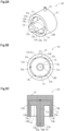
- FIG. 3(A) is a perspective view schematically illustrating an example of the suction portion 10 provided in the head 126 of the apparatus for taking out molded product 120 according to the one embodiment of the present invention.
- FIG. 3(B) is a front view schematically illustrating the suction portion 10.
- FIG. 3(C) is a transverse cross-sectional view schematically illustrating the suction portion 10.
- FIG. 4(A) is a front view schematically illustrating the state where the suction portion 10 illustrated in FIGS. 3(A) to 3(C) holds the hollow molded product 20.
- FIG. 3(B) is a transverse cross-sectional view schematically illustrating the state where the suction portion 10 holds the hollow molded product 20.
- the hollow molded product 20 in this embodiment is a closed-bottom cylindrical beverage container, including an opening portion (21) served as an opening for drinking, a body portion 23 made up of a cylinder with the same diameter, and a shoulder portion 22 smoothly connecting to the opening portion 21. Since the opening portion 21 is configured to be sealed by heat sealing, the hollow molded product 20 does not have a flange portion (cap screw portion) like the flange portion used to hold a molded product by the foregoing related-art apparatus for taking out molded product.
- the opening portion 21 is formed as a thick portion whose entire circumference is thicker than the wall thickness of the other parts of the hollow molded product 20, at the time of injection molding of the foregoing closed-bottom parison as the preform 19.
- each of the plural suction portions 10 provided in the head 126 of the apparatus for taking out molded product 120 has a structure in which an insert portion 12 and an abutting portion 13 are formed at a circular columnar base plate 11.
- the insert portion 12 has a circular columnar shape concentric with the centerline of the base plate 11 and extending along an imaginary centerline of the base plate 11.
- the diameter of the transverse cross section of the insert portion 12 is smaller than the diameter of the opening portion 21 of the hollow molded product 20 to be taken out.
- the opening portion 21 is an extraction port for a blow pin inserted in the hollow molded product 20 in order to blow-mold the hollow molded product 20 in the blow mold, and the insert portion 12 is inserted in the hollow molded product 20 through the opening portion 21.
- the insert portion 12 has, at a distal end part, plural suction ports 12b that suck the ambient atmosphere.
- the insert portion 12 has one suction port 12b at the center of a distal end 12a, and the four suction ports 12b formed at equal intervals on the outer circumferential surface near the distal end 12a.
- Each suction port 12b is connected to an air flow path 12c arranged in the insert portion 12, and the other end of the air flow path 12c is connected to a pipe connection portion 15 protruding from the outer circumferential surface of the base plate 11.
- a vacuum pump or a vacuum generator is, for example, connected to the pipe connection portion 15 through an open/close valve or the like. Switching the opening and closing of the open/close valve and the supply and no-supply of a pressurized gas to the vacuum generator performs on and off the suction by the plural suction ports 12b (sucking state and non-sucking state).
- the non-sucking state includes a pressurized state, as will be described later.
- the abutting portion 13 has a cylindrical shape extending along the imaginary centerline of the base plate 11 so as to be concentric with the imaginary centerline of the base plate 11.
- the length in the axial direction of the abutting portion 13 is smaller than the length in the axial direction of the insert portion 12.
- the outer diameter of the base plate 11 and the outer diameter of the abutting portion 13 are the same, and the outer circumferential surface of the base plate 11 and the outer circumferential surface of the abutting portion 13 form a continuous outer circumferential surface.
- annular recess 14 is provided between the insert portion 12 and the abutting portion 13.
- the annular recess 14 accommodates the opening portion 21 of the hollow molded product 20 to be taken out.
- an annular abutting surface 13b of the cylindrical abutting portion 13 continuously abuts on the outer circumferential surface of the hollow molded product 20 spaced apart by a predetermined distance from the opening portion 21 of the hollow molded product 20.
- the abutting portion 13 abuts on the outer circumferential surface formed of the shoulder portion 22, as illustrated in FIG. 4 (A) and FIG. 4 (B) .
- the annular recess 14 forms a closed space 26 communicating with an internal space 24 of the hollow molded product 20.
- the closed space 26 is not necessary a completely airtight closed space and may be any space that can reduce the pressure in the hollow molded product 20 by the suction through the suction port 12b of the insert portion 12.
- the inside of the hollow molded product 20 can be depressurized by the suction through the suction port 12b of the insert portion 12, for example, a configuration in which a gap exists between the outer circumferential surface of the hollow molded product 20 and the abutting surface 13b of the abutting portion 13, or a configuration in which a penetration hole, an opening portion or the like exists on the cylindrical surface forming the abutting surface 13b of the abutting portion 13, may be adopted.
- an inclined surface aligned with the shoulder portion 22 of the hollow molded product 20 forms the abutting surface 13b, as illustrated in FIG. 4(A) and FIG. 4(B) .
- the abutting surface 13b formed by the inclined surface is provided with a predetermined width at the inner circumferential edge of the abutting portion 13.
- the abutting portion 13 has additional suction ports 13c that suck the outer circumferential surface of the hollow molded product 20, on the inclined surface, which is the abutting surface 13b abutting on the hollow molded product 20.
- the six additional suction ports 13c are arranged at equal intervals on the inclined surface, which is the abutting surface 13b.
- Each additional suction port 13c is connected to an air flow path 13d arranged in the abutting portion 13, and the other end of the air flow path 13d is connected to the air flow path 12c.
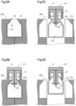
- FIGS. 5(A) to 5(D) are views schematically illustrating the process for the foregoing suction portion 10 to hold the hollow molded product 20.
- FIG. 5(A) is a view illustrating the state where the blow pin-rod 233 or 234 having injected the blow air is extracted from the opening portion 21 of the hollow molded product 20, which is the blow pin extraction port, after the preform 19 [ FIG. 2(A) ] is molded by the blow air into the shape corresponding to the cavity 221 of the movable mold 202, which is the blow mold.
- the movable mold 202 is bisected along a vertical plane including the imaginary centerline of the body portion 23 of the hollow molded product 20.
- a space is formed so that the hollow molded product 20 can be taken out in the vertical direction or the direction in which the imaginary centerline of the body portion 23 extends, without interfering with the movable mold 202.
- a recess aligned with the foregoing thick portion forming the opening portion 21 is provided at a position corresponding to the opening portion 21 of the hollow molded product 20.
- the preform 19 is arranged in the cavity 221 of the movable mold 202, the entirety of the preform 19 is accommodated in the movable mold 202 and the preform 19 (and the hollow molded product 20) has a configuration without having a portion protruding out of the movable mold 202.
- the suction portion 10 is arranged in relation to the hollow molded product 20 so that the opening portion 21 and the insert portion 12 face each other, and the insert portion 12 is inserted in the hollow molded product 20 through the opening portion 21, as illustrated in FIG. 5(B) .
- the insert portion 12 is inserted in the hollow molded product 20 by moving in the horizontal direction.
- the length in the direction of the imaginary centerline of the insert portion 12 is designed in such a way that the distal end 12a of the insert portion 12 is in the state of being arranged nearby a changeover part between the shoulder portion 22 and the body portion 23, in the direction in which the imaginary centerline of the hollow molded product 20 extends.
- the movable mold 202 is put into the split-mold opened state, as illustrated in FIG. 5(C) .
- the hollow molded product 20 moves to the proximal end (base plate 11) of the insert portion 12 due to the air flow flowing in from the opening portion 21.
- the opening portion 21 of the hollow molded product 20 is accommodated in the recess 14 and the shoulder portion 22 of the hollow molded product 20 abuts on the inclined surface, which is the abutting surface 13b of the abutting portion 13, as illustrated in FIG. 5(D) .
- a continuous hollow space is formed by the recess 14 and the internal space of the hollow molded product 20.
- the movement of the opening portion 21 to the recess 14 is prompted by the air flow caused by the suction through the suction ports 13c of the abutting portion 13, and the state where the shoulder portion 22 abuts on the abutting surface 13b is maintained by the suction through the suction ports 13c. Also, since the suction of the ambient atmosphere from the suction ports 12b of the insert portion 12 is continued even in this state, the shoulder portion 22 of the hollow molded product 20 is pressed against the abutting surface 13b and the shoulder portion 22 of the hollow molded product 20 is supported by the abutting portion 13 more securely.
- the hollow molded product 20 can be taken out from the movable mold 202.
- the molding system 100 (apparatus for taking out molded product 120) including the suction portion 10 according to this embodiment, even the hollow molded product 20 without having a portion protruding from the movable mold 202 can be taken out from the movable mold 202 without coming into contact with the opening portion 21 and the inner surface of the hollow molded product 20.
- a hollow molded product to which a reduction in thickness and weight or a material change to use a biodegradable resin or the like is applied can be taken out from the blow mold while avoiding damage to the hollow molded product and contamination of the opening portion.
- the abutting surface 13b formed by the inclined surface at the inner circumferential edge of the abutting portion 13 may be formed by a corner portion or a curved surface.
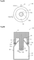
- FIG. 6(A) is a front view schematically illustrating the suction portion 40.
- FIG. 6(B) is a transverse cross-sectional view schematically illustrating the suction portion 40.
- the suction portion 40 illustrated in FIG. 6(A) and FIG. 6 (B) is different from the suction portion 10 described when using FIGS. 3(A) to 3(C) only in the configuration of the abutting portion 13.
- the other configurations are the same and therefore the same elements are denoted by the same reference numerals as in FIGS. 3(A) to 3(C) .
- the suction portion 40 is used in place of the foregoing suction portion 10 in the molding system 100.
- the suction portion 40 differs from the foregoing suction portion 10 in having an elastic member 13e at a position with a predetermined length from a distal end 13a of the abutting portion 13 including an abutting surface abutting on the hollow molded product 20.
- the material of the elastic member 13e is not particularly limited, for example, a rubber material such as silicone rubber, nitrile rubber or urethane rubber can be utilized.
- the suction portion 40 also differs in not having the abutting surface 13b formed by an inclined surface, the additional suction ports 13c, and the air flow path 13d provided in the foregoing suction portion 10, since the elastic member 13e forms the entirety of the distal end 13a of the abutting portion 13.
- any shape such as a curved surface can be adopted as the surface shape of the elastic member 13e.
- a configuration without having the abutting surface 13b formed by an inclined surface, the additional suction ports 13c, and the air flow path 13d is configured in the example illustrated in FIG. 6 , even the abutting portion 13 having the elastic member 13e can have the abutting surface 13b formed by an inclined surface, the additional suction ports 13c, and the air flow path 13d.
- the entirety of the abutting portion 13 or the entirety of the suction portion 40 may be formed by an elastic member.
- the suction ports 12b of the insert portion 12 of the suction portion 10 need to function as an injection port that injects a pressurized gas. Therefore, in this example, a vacuum system that provides a suction force for the suction ports 12b and a gas supply system that supplies a pressurized gas to the suction ports 12b are connected in a switchable manner to the pipe connection portion 15 of the suction portion 10.
- Such a configuration can be achieved, for example, by using a vacuum pump as the vacuum system and using a compressor as the gas supply system, and connecting each system and the pipe connection portion 15 through a three-way valve or the like.
- a vacuum pump as the vacuum system
- a compressor as the gas supply system
- This configuration can achieve the function as the vacuum system by supplying a pressurized gas from the compressor to the ejector and can also make the compressor function as the gas supply system.
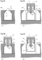
- FIG. 7(A) is a view illustrating the state where, after a preform is molded into a shape corresponding to a cavity 241 of a movable mold 204 by a blow air, the blow pin (the foregoing blow pin-rod 233 or 234) that has injected the blow air is extracted from the opening portion 21 of the hollow molded product 20, which is the blow pin extraction port.
- the movable mold 204 is utilized in place of the foregoing movable mold 202 in the molding system 100.
- the movable mold 204 is configured in such a way that a mold portion 242 corresponding to the bottom portion of the hollow molded product 20 does not move when in the split-mold opened state.
- the movable mold 204 except for the mold portion 242 is bisected along a vertical plane including the imaginary centerline of the body portion 23 of the hollow molded product 20 and can perform split-mold opening and closing actions, similarly to the movable mold 202.
- the hollow molded product 20 when in the split-mold opened state, a space is formed so that the hollow molded product 20 can be taken out in the vertical direction or the direction in which the imaginary centerline of the body portion 23 extends, without interfering with the movable mold 204.
- the suction portion 10 is arranged so that the opening portion 21 and the insert portion 12 are in a positional relationship facing each other, and the insert portion 12 is inserted into the hollow molded product 20 through the opening portion 21, as illustrated in FIG. 7(B) .
- the state is switched to a state in which a pressurized gas is injected from the suction ports 12b of the insert portion 12 and the additional suction ports 13c of the abutting portion 13. That is, when the suction ports 13c are switched to the injection port, the hollow molded product 20 turns into the state of being pressed against the movable mold 204.
- the movable mold 204 except for the mold portion 242 facing to the bottom portion of the hollow molded product 20 is put into the split-mold opened state, the hollow molded product 20 is held in the state where the bottom portion of the hollow molded product 20 is pressed against the mold portion 242 facing to the bottom portion, as illustrated in FIG. 7(C) .
- the suction ports 12b of the insert portion 12 and the additional suction ports 13c of the abutting portion 13 are switched to the sucking state.
- the ambient atmosphere is sucked from the suction ports 12b of the insert portion 12 and an air flow flowing into the hollow molded product 20 from outside through the opening portion 21 is generated.
- the hollow molded product 20 moves to the proximal end of the insert portion 12 due to the air flow flowing in from the opening portion 21.
- the opening portion 21 of the hollow molded product 20 is accommodated in the recess 14 and the shoulder portion 22 of the hollow molded product 20 abuts on the abutting surface 13b formed by the inclined surface of the abutting portion 13, as illustrated in FIG.
- the shoulder portion 22 of the hollow molded product 20 is supported by the abutting portion 13 more securely, as in the example illustrated in FIG. 5(D) .
- the abutting surface 13b formed by the inclined surface may be brought closer to the shoulder portion 22 and furthermore the abutting surface 13b formed by the inclined surface may be made to abut on the shoulder portion 22, by moving the suction portion 10 in the direction of the hollow molded product 20.
- the hollow molded product 20 can be taken out from the movable mold 204.
- the hollow molded product 20 without having a portion protruding from the movable mold 204 can be taken out from the movable mold 204 without coming into contact with the opening portion 21 and the inner surface of the hollow molded product 20.
- a molded product to which a reduction in thickness and weight or a material change to use a biodegradable resin or the like is applied can be taken out from the blow mold while avoiding damage to the hollow molded product and contamination of the opening portion.
- the additional suction ports 13c can also be utilized as an injection port to inject a pressurized gas. Therefore, for example, when releasing the hollow molded product 20 that has been taken out, from the apparatus for taking out molded product 120, the hollow molded product 20 can be more securely released by injecting a pressurized gas from the suction ports 13c served as the injection port of the abutting portion 13.
- the abutting portion 13 it is not essential for the abutting portion 13 to include both the suction ports and the injection port, and a configuration in which the abutting portion 13 does not have either one of the suction ports and the injection port or has neither one, can be adopted.
- an ejector is arranged outside the suction portion 10
- FIG. 8(A) is a view illustrating the state where, after a preform is molded into a shape corresponding to a cavity 251 of a movable mold 205 by a blow air, the blow pin (the foregoing blow pin-rod 233 or 234) that has injected the blow air is extracted from the opening portion 21 of the hollow molded product 20, which is the blow pin extraction port.
- the movable mold 205 is utilized in place of the foregoing movable mold 202 in the molding system 100.
- the movable mold 205 comprises the first mold member 252 forming a cavity portion abutting on a circumferential edge portion of the bottom portion of the hollow molded product 20, and the second mold member 253 forming a cavity portion abutting on a center portion of the bottom portion of the hollow molded product 20.
- the second mold member 253 is a circular columnar member concentric with the imaginary centerline of the body portion 23 of the hollow molded product 20 and is configured to be able to move forward and backward in the axial direction by a drive source such as a hydraulic cylinder or the like, not illustrated.
- the movable mold 205 is bisected along a vertical plane including the imaginary centerline of the body portion 23 of the hollow molded product 20 and can perform split-mold opening and closing actions, similarly to the movable mold 202.
- a space is formed so that the hollow molded product 20 can be taken out in the vertical direction or the direction in which the imaginary centerline of the body portion 23 extends, without interfering with the movable mold 204.
- the first mold member 252 has a first bottom wall surface portion 251Aa of a bottom wall surface 251A of a cavity 251, as a constituent surface of the cavity.
- the second mold member 253 is provided adjacent to the first mold member 252 and has a second bottom wall surface portion 251Ab of the bottom wall surface 251A of the cavity 251, as a constituent surface of the cavity.
- the first bottom wall surface portion 251Aa of the first mold member 252 and the second bottom wall surface portion 251Ab of the second mold member 253 form the bottom wall surface 251A of the cavity 251 when in the closed-mold state.
- the mold equipment 114 sucks and holds the hollow molded product to the first bottom wall surface portion 251Aa of the first mold member 252.
- the second mold member 253 is moved in such a way as to form the recessed part 254 between the second bottom wall surface portion 251Ab of the second mold member 253 and the outer surface of the hollow molded product. Also, with the movement of the second mold member 253, a suction port 255a is exposed, the suction port 255a being provided in the wall surface of the recessed part 254 formed by the first mold member 252.
- the suction port 255a is connected to an air flow path 255 provided in the first mold member 252, and the other end of the air flow path 255 is connected to a vacuum pump or a vacuum generator through an open/close valve or the like.
- the suction port 255a By switching the opening and closing of the open/close valve and the supply and non-supply of a pressurized gas to the vacuum generator, on and off (sucking state and non-sucking state) of the suction at the suction port 255a are switched.
- the suction port 255a also functions as an injection port that injects a pressurized gas. Therefore, a vacuum system that provides a suction force for the suction port 255a and a gas supply system that supplies a pressurized gas to the suction port 255a are connected in a switchable manner to the other end of the air flow path 255.
- the suction port 255a As the suction port 255a is exposed in the recessed part 254 with the movement of the second mold member 253, the suction port 255a is switched to the sucking state.
- the hollow molded product 20 is in the state of being sucked and held in the state where the circumferential edge portion of the bottom surface abuts on the first mold member 252. That is, the mold equipment 114 can be put in the suction-holding state where the hollow molded product is sucked and held at the first bottom wall surface portion 251Aa of the first mold member 252, by bringing into a depressurized state in the recessed part 254.
- the suction portion 10 is arranged in the state where the opening portion 21 and the insert portion 12 face each other, and the insert portion 12 is inserted into the hollow molded product 20 through the opening portion 21, as illustrated in FIG. 8(B) .
- the suction ports 12b of the insert portion 12 and the suction ports 13c of the abutting portion 13 are switched to the sucking state.
- the ambient atmosphere is sucked from the suction ports 12b of the insert portion 12 and an air flow flowing into the hollow molded product 20 from outside through the opening portion 21 is generated.
- bringing into a nondepressurized state in the recessed part 254 forms the non-suction-holding state where the hollow molded product is not sucked and held at the first bottom wall surface portion 251Aa of the first mold member 252.
- the suction port 255a exposed in the recessed part 254 is switched to the state of injecting the pressurized gas.
- the sucking and holding of the bottom portion of the hollow molded product 20 is cancelled, and the hollow molded product 20 moves to the proximal end side of the insert portion 12 due to the pressurized gas injected from the suction port 255a and the air flow flowing in from the opening portion 21.
- the opening portion 21 of the hollow molded product 20 is accommodated in the recess 14 and the shoulder portion 22 of the hollow molded product 20 abuts on the abutting surface 13b formed by the inclined surface of the abutting portion 13, as illustrated in FIG. 8(D) .
- the shoulder portion 22 of the hollow molded product 20 is supported by the abutting portion 13 more securely, as in the example illustrated in FIG.
- the abutting surface 13b may be brought closer to the shoulder portion 22 and furthermore the abutting surface 13b may be made to abut on the outer circumferential surface forming the shoulder portion 22, by moving the suction portion 10 in the direction of the hollow molded product 20 when the movable mold 205 is put in the split-mold opened state.
- the hollow molded product 20 can be taken out from the movable mold 204.
- the hollow molded product 20 without having a portion protruding from the movable mold 204 can be taken out from the movable mold 204 without coming into contact with the opening portion 21 and the inner surface of the hollow molded product 20.
- a hollow molded product to which a reduction in thickness and weight or a material change to use a biodegradable resin or the like is applied can be taken out from the blow mold in the state where damage to the molded product and contamination of the opening portion are avoided.
- the suction port 255a is also served as an injection port to inject a pressurized gas
- a configuration in which the recessed part 254 has an injection port provided independently of the suction port 255a can be adopted.
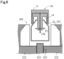
- the second mold member 253 may be provided to be movable in the direction of pressing the hollow molded product 20, as illustrated in FIG. 9 , in place of the injection port to inject the pressurized gas.
- the insert portion 12 is inserted in the hollow molded product 20 when in the split-mold closed state as illustrated in FIG. 8(B) in view of the fall prevention of the hollow molded product 20.
- the insert portion 12 may be inserted into the hollow molded product 20 when after turned into the split-mold opened state.
- the second mold member 253 is driven.
- the first mold member 252 and the second mold member 253 may be required to be movable relatively to each other. Also, it is not essential to provide the suction port 255a.
- a suction force to the molded product can be generated by arranging the cavity constituent surface of the first mold member and the cavity constituent surface of the second mold member differently from the closed-mold state.
- a configuration in which the molded product is sucked and held by this suction force may be also adopted.
- the part of the molded product that is sucked and held is not limited to the bottom portion, and other parts may be sucked and held.
- the number, shape, and arrangement position of suction ports, and the number, shape, and arrangement position of injection ports in the above-described suction portion are simply examples and can be modified where appropriate.
- the number, shape, and arrangement position of recesses and protrusions in the above-described mold equipment are simply examples and can be modified where appropriate.
- the physical shape and material of the foregoing elements can be arbitrarily modified within a scope that achieves the effects of the present invention.
- a molded product without having a portion protruding from the blow mold can be taken out from the blow mold without coming into contact with the opening portion and the inner surface, and this is advantageous as a molding system, an apparatus for taking out molded product, a mold equipment, a molding machine, and a method for driving a mold equipment.
Landscapes
- Engineering & Computer Science (AREA)
- Manufacturing & Machinery (AREA)
- Mechanical Engineering (AREA)
- Moulds For Moulding Plastics Or The Like (AREA)
- Blow-Moulding Or Thermoforming Of Plastics Or The Like (AREA)
Abstract
Description
- The present invention relates to a molding system, an apparatus for taking out molded product, a mold equipment, a molding machine, and a method for manufacturing a hollow molded product.
- According to the related art, blow molding is widely used for molding a hollow resin container such as a polyethylene terephthalate (PET) bottle. As already known, in blow molding, a hollow preform (parison) is arranged in a blow mold and subsequently a blow pin is arranged in the preform. As a blow air is blown into the preform through the blow pin, the preform is molded into a shape corresponding to the cavity of the blow mold.
- The molded product is taken out of the blow mold when being opened by an apparatus for taking out molded product. When being taken-out, a method of making the molded product fall out of the blow mold (for example, Patent Literature 1) or a method of taking out the molded product from the blow mold in the state where a flange portion (cap screw portion) of the preform protruding out of the blow mold, when the preform is arranged in the blow mold, is supported or the like (for example, Patent Literature 2) is adopted.
-
- Patent Literature 1:
JP2006-035672A - Patent Literature 2:
JP2007-069241A - Recently, a reduction in thickness and weight of a resin container and a material change to use a biodegradable resin or the like are demanded from the viewpoint of environmental protection, and the manufacture of a resin container with lower strength than a traditional one is needed. In the process of manufacturing such a resin container, if the above-mentioned falling method is used to take out a molded product from a blow mold, the molded product may be frequently damaged.
- On the other hand, the above-mentioned method for taking out, in which the flange portion of the preform is supported, can avoid damage to the molded product since each molded product can be separately taken out. However, it is difficult for a resin container to use the method of supporting the flange portion in case that the resin container does not have a portion such as the flange portion protruding from the blow mold.
- As a technique for individually taking out a resin container that does not have a portion protruding from the blow mold, it is conceivable to take out the molded product from the blow mold in the state where the inner circumferential surface of the opening portion of the molded product with a blow pin inserted in the molded product is supported. However, in the case of a resin container used to contain a food or drink such as a beverage, a support member for taking out the molded product needs to avoid abutting on the opening portion or the inner surface of the container from the viewpoint of hygiene.
- An object of the present invention is to provide a molding system that can take out a molded product from the blow mold without coming into contact with the opening portion or the inner surface of the hollow molded product even if the molded product does not have a portion protruding from a blow mold.
- Another object of the present invention is to provide an apparatus for taking out molded product that is suitable for using in the molding system.
- Still another object of the present invention is to provide a mold equipment that is suitable for using in the molding system.
- Still another object of the present invention is to provide a method for manufacturing a hollow molded product, using the molding system.
- A configuration of the present invention to solve the foregoing problems will be described below. In order to facilitate understanding, the configuration of the present invention is described with reference numerals given in the drawings. However, the use of the reference numerals is not to limit the present invention to an embodiment.
- In order to achieve the foregoing objects, the molding system according to the present invention is assumed to be a molding system for manufacturing a hollow molded
product 20 by blow molding. The molding system according to the present invention has amolding machine 110 and an apparatus for taking out moldedproduct 120. Themolding machine 110 has amold equipment 114 in which a hollow molded product is blow-molded in a cavity (221, 241, 251). The apparatus for taking out moldedproduct 110 sucks the hollow molded product molded in themold equipment 114 by asuction portion 10 and takes out the hollow molded product from the mold equipment. In this apparatus for taking out moldedproduct 120, thesuction portion 10 has aninsert portion 12, anabutting portion 13, arecess 14 provided between theinsert portion 12 and theabutting portion 13, and asuction port 12b. Theinsert portion 12 is inserted in the hollow molded product through anopening portion 21 served as a blow pin extraction port of the hollow molded product. The abuttingportion 13 is arranged, spaced apart from theinsert portion 12, and abuts on a part of an outercircumferential surface 22 of the hollow moldedproduct 20 that is spaced apart by a predetermined distance from theopening portion 21 served as the blow pin extraction port. Therecess 14 is provided between theinsert portion 12 and theabutting portion 13 and forms a closedspace 26 communicating with aninternal space 24 in the hollow molded product when the part of the hollow molded product where theopening portion 21 served as the blow pin extraction port is formed is accommodated in therecess 14 in the state where the abuttingportion 13 is abutting on the outercircumferential surface 22 of the hollow molded product. Thesuction port 12b is provided in theinsert portion 12 and sucks the air in theinternal space 24 and the closedspace 26. - In this molding system, for example, when the
insert portion 12 is inserted through the blow pin extraction port (opening portion 21) of the hollow molded product molded in themold equipment 114 and the mold equipment is opened in the state where the ambient atmosphere is sucked from thesuction port 12b of the insert portion, the hollow moldedproduct 20 moves toward the proximal end side of theinsert portion 12 due to an air flow that flows in from theopening portion 21 of the hollow moldedproduct 20, which is the blow pin extraction port. With this movement of the hollow molded product, theopening portion 21 of the hollow molded product, which is the blow pin extraction port, is accommodated in therecess 14. Also, the outercircumferential surface 22 of the hollow molded product, spaced apart by the predetermined distance from theopening portion 21, which is the blow pin extraction port, abuts on the abuttingportion 13. As the result, the recess 14 and theinternal space 24 in the hollow moldedproduct 20 form a continuous closedspace 26. Since the suction of the ambient atmosphere from thesuction port 12b of theinsert portion 12 is continued even in this state, the outercircumferential surface 22 of the hollow molded product is pressed against theabutting portion 13 and the outercircumferential surface 22 of the hollow molded product can be supported by theabutting portion 13 more securely. As the hollow molded product is moved in such a state, even the hollow molded product without having a portion such as a flange portion protruding from the mold equipment can be taken out from themold equipment 114 without making theinsert portion 12 come into contact with the opening portion and the inner surface of the hollow molded product. - More specifically in the
suction portion 10, acoupling portion 11 that couples theinsert portion 12 with theabutting portion 13 and that forms a recess between the insert portion and the abutting portion is provided. Anadditional suction port 13c that sucks the outercircumferential surface 22 of the hollow molded product is provided at anabutting surface 13b abutting on the hollow molded product, of theabutting portion 13. Also, anair flow path 13d communicating with thesuction port 12b and theadditional suction port 13c is formed in theinsert portion 12, thecoupling portion 11, and theabutting portion 13. Thesuction port 12b of theinsert portion 12 and theadditional suction port 13c can also be used as an injection port to inject a pressurized gas. If a configuration in which theinsert portion 12 has an injection port to inject a pressurized gas is adopted, when theinsert portion 12 is inserted through theopening portion 21 of the hollow molded product molded in the mold equipment and a pressurized gas is injected from theinjection port 12b of the insert portion, the hollow moldedproduct 20 is pressed against the mold equipment. When, in this state, the mold equipment is in a split-mold opened state except for a mold portion corresponding to a bottom portion of the hollow moldedproduct 20 that faces the distal end of theinsert portion 12, the bottom portion of the hollow moldedproduct 20 is held in the state of being pressed against the mold portion corresponding to this bottom portion. In this state, theabutting portion 13 is advanced, and when theabutting portion 13 has advanced to a position to abut on the outercircumferential surface 22 of the hollow molded product, the suction of the ambient atmosphere is started from thesuction port 12b of theinsert portion 12. Thus, the outercircumferential surface 22 of the hollow moldedproduct 20 is pressed against theabutting portion 13, and the outercircumferential surface 22 of the hollow moldedproduct 20 is supported by theabutting portion 13. Therefore, the outercircumferential surface 22 of the hollow molded product can be made to securely abut on the abuttingsurface 13b of the abuttingportion 13. Also, if thesuction port 13c of the abuttingportion 13 is switched to the injection port and the pressurized gas is injected from theinjection port 13c of the abuttingportion 13 when taking out the molded product that has been taken out, from the apparatus for taking out molded product, the molded product can be released more securely. - As a matter of course, the
abutting portion 13 may also have anelastic member 13e at the abutting surface abutting on the hollow molded product. As theelastic member 13e is provided, the shape of the abutting surface of the abuttingportion 13 is deformed in a state aligned with the outer circumferential surface of the molded product and therefore the contact area between the outer circumferential surface of the molded product and the abutting surface of the abuttingportion 13 increases. As a result, the outer circumferential surface of the molded product can be supported by the abutting portion more securely. - The
mold equipment 114 used in the molding system according to the present invention has afirst mold member 252 forming a part of the cavity 251, and asecond mold member 253 provided adjacent to thefirst mold member 252 and forming a part of the cavity 251. Themold equipment 114 may be configured in such a way that a constituent surface 251Aa of the cavity of thefirst mold member 252 and a constituent surface 251Ab of the cavity of the second mold member are arranged differently from a closed-mold state and that the hollow molded product molded in the cavity is sucked and held in the state of abutting on the constituent surface 251Aa of the cavity of the first mold member. In this mold equipment, since the hollow molded product is sucked and held in the mold equipment, the hollow molded product is held in the mold equipment even when the mold equipment is in a split-mold opened state in order to take out the molded product. Therefore, the molded product can be easily taken out. - The
first mold member 252 has the first bottom wall surface portion 251Aa of abottom wall surface 251A of the cavity 251, as a constituent surface of the cavity. The second mold member has the second bottom wall surface portion 251Ab of thebottom wall surface 251A of the cavity 251, as a constituent surface of the cavity. The first bottom wall surface portion 251Aa of thefirst mold member 252 and the second bottom wall surface portion 251Ab of thesecond mold member 253 form thebottom wall surface 251A of the cavity 251 when in the closed-mold state. Also, themold equipment 114 can be configured in such a way that the hollow molded product is sucked and held at the first bottom wall surface portion 251Aa of thefirst mold member 252 after the hollow moldedproduct 20 is molded. - Specifically in the
mold equipment 114, thesecond mold member 253 is moved so as to form arecessed part 254 between the second bottom wall surface portion 251Ab of thesecond mold member 253 and the outer surface of the hollow molded product after the hollow molded product is molded. In themold equipment 114, a suction-holding state, where the hollow molded product is sucked and held to the first bottom wall surface portion 251Aa of thefirst mold member 252 by bringing an inside of therecessed part 254 into a depressurized state, is prepared. Also, it can be configured in such a way that a non-suction-holding state, where the hollow molded product is not sucked and held to the first bottom wall surface portion 251Aa of thefirst mold member 252 is provided by bringing the inside of therecessed part 254 into a non-depressurized state, is formed. The suction-holding state is provided by bringing an inside of the recessedpart 254 into a depressurized state, and the non-suction-holding state is provided by bringing the inside of the recessedpart 254 into a non-depressurized state or a pressurized state in the recessedpart 254. The suction-holding state can be achieved by providing asuction port 255a that is exposed inside the recessedpart 254 and that sucks the atmosphere inside the recessedpart 254. According to these configurations, the hollow molded product is sucked and held in the state of abutting on the first bottom wall surface portion 252Aa, which is the constituent surface of the cavity 251 of thefirst mold member 252. With the above configurations, the hollow molded product is sucked and held in the mold equipment and therefore the molded product is held in the mold equipment even when the mold equipment is in the split-mold opened state in order to take out the molded product. Therefore, the outer circumferential surface of the hollow molded product can be made to abut on the abuttingportion 13 more securely and the hollow molded product can be taken out more easily. - The
mold equipment 114 may also haveplural mold members 205 forming the wall surface except thebottom wall surface 251A of the cavity 251. In this case, it may be configured in such a way that the suction state is maintained for a predetermined period after theplural mold members 205 are taken out from the molded product, or thesecond mold member 253 may move in such a way as to move the hollow moldedproduct 20 in a direction away from the first bottom wall surface portion 251Aa after theplural mold members 205 are taken out from the hollow moldedproduct 20. To achieve this, thesecond mold member 253 is provided in such a way as to movable in a direction of pressing the hollow molded product molded in the cavity. Thus, the hollow moldedproduct 20 can be made to securely abut on the abuttingportion 13 of thesuction portion 10. Also, theinjection port 255a that is exposed in the recessedpart 254 and that injects a pressurized gas in the recessedpart 254 may be provided, instead of moving thesecond mold member 253. - The present invention can also be understood as a method for manufacturing a hollow molded product by blow molding, using the molding machine having the
mold equipment 114, in which the hollow molded product is blow-molded in the cavity (221, 241, 251), and the apparatus for taking out moldedproduct 120, in which the hollow moldedproduct 20 molded in the mold equipment is sucked by thesuction portion 10 and taken out from the mold equipment. In this method, first, themold equipment 114 having the first mold member and the second mold member is prepared. Thefirst mold member 252 has the first bottom wall surface portion 251Aa of thebottom wall surface 251A of the cavity 251, and thesecond mold member 253 is provided adjacent to thefirst mold member 252 and has the second bottom wall surface portion 251Ab of the bottom wall surface of the cavity. Next, the bottom wall surface of the cavity is formed when the first bottom wall surface portion 251Aa of thefirst mold member 252 and the second bottom wall surface portion 251Ab of thesecond mold member 253 are in the closed-mold state. Then, after the hollow moldedproduct 20 is molded, the hollow moldedproduct 20 is sucked and held at the first bottom wall surface portion 251Aa of thefirst mold member 252. - Also, in a method for taking out molded product in which a molded product formed by blow molding is taken out from the mold equipment of the molding machine, first, a pressurized gas is injected into the molded product held in the mold equipment. Next, the mold equipment is opened in the state where the pressurized gas is injected. Subsequently, the closed
space 26 communicating with the inside of the hollow molded product is formed in the state where the mold equipment is opened. Then, after the closed space is formed, the inside of the closed space is depressurized. In this method for taking out molded product, for example, when the pressurized gas is injected into the hollow molded product molded in the blow mold, the hollow molded product is getting into the state of being pressed against the blow mold. When the blow mold except the mold portion corresponding to the bottom portion of the hollow molded product is opened in this state, the bottom portion of the hollow molded product is held in the state of being pressed against the mold portion corresponding to this bottom portion. When the inside of the closed space communicating with the inside of the molded product is depressurized in this state, the hollow molded product can be held in the apparatus for taking out moldedproduct 120. Therefore, even if the hollow molded product does not have a portion protruding from the blow mold, the hollow molded product can be taken out from the blow mold without coming into contact with the opening portion and the inner surface of the hollow moldedproduct 120. - According to the present invention, even if a hollow molded product does not have a portion protruding from the blow mold, the hollow molded product can be taken out from the blow mold without coming into contact with the opening portion and the inner surface of the hollow molded product.
-
- [
FIG. 1] FIG. 1 is a perspective view schematically illustrating an example of a molding system according to one embodiment of the present invention. - [
FIG. 2] FIG. 2(A) is a side view schematically illustrating an opened-mold state of a mold equipment provided in the molding system according to the one embodiment of the present invention.FIG. 2(B) is a side view schematically illustrating a closed-mold state of the mold equipment provided in the molding system according to the one embodiment of the present invention. - [
FIG. 3] FIG. 3(A) is a perspective view schematically illustrating an example of a suction portion of an apparatus for taking out molded product provided in the molding system according to the one embodiment of the present invention.FIG. 3(B) is a front view schematically illustrating the suction portion.FIG. 3(C) is a transverse cross-sectional view schematically illustrating the suction portion. - [
FIG. 4] FIG. 4(A) is a front view schematically illustrating the state where the suction portion illustrated inFIG. 3 holds a molded product.FIG. 4(B) is a transverse cross-sectional view schematically illustrating the suction portion. - [
FIG. 5] FIGS. 5(A)-(D) are views schematically illustrating an example of a process in which the suction portion illustrated inFIG. 3 holds the molded product. - [
FIG. 6] FIG. 6(A) is a front view schematically illustrating another example of the suction portion of the apparatus for taking out molded product provided in the molding system according to the one embodiment of the present invention.FIG. 6(B) is a transverse cross-sectional view schematically illustrating the suction portion. - [
FIG. 7] FIGS. 7(A)-(D) are views schematically illustrating another example of the process in which the suction portion illustrated inFIG. 3 holds the molded product. - [
FIG. 8] FIGS. 8(A)-(D) are views schematically illustrating another example of the process in which the suction portion illustrated inFIG. 3 holds the molded product. - [
FIG. 9] FIG. 9 is a view schematically illustrating a modified example of the mold equipment provided in the molding system according to the one embodiment of the present invention. - Embodiments of the present invention will now be described in detail with reference to the drawings. In the embodiment below, the present invention is embodied in a molding system that includes a molding machine having a mold equipment performing injection molding of a preform and blow molding of a molded product in parallel, and a so-called traverse-type apparatus for taking out molded product.
-
FIG. 1 is a schematic perspective view of the molding system according to the embodiment.FIG. 2(A) and FIG. 2(B) are side views schematically illustrating the mold equipment provided in the molding system.FIG. 2(A) corresponds to an opened-mold state.FIG. 2(B) corresponds to a closed-mold state. InFIG. 1 , the description of a support frame and an intermediate mold illustrated inFIG. 2(A) and FIG. 2(B) is omitted. - As illustrated in
FIG. 1 , amolding system 100 has amolding machine 110, and an apparatus for taking out moldedproduct 120 that takes out a molded product molded in themolding machine 110. Although not particularly limited, amold equipment 114 provided in themolding machine 110 has acavity 211 functioning as an injection mold and acavity 221 functioning as a blow mold. In thecavity 211 functioning as the injection mold, a closed-bottom parison that is apreform 19 is injection-molded. Thispreform 19 is moved to thecavity 221 functioning as the blow mold and a desired hollow molded product corresponding to the blow mold is blow-molded in thecavity 221. - The
molding machine 110 has a known structure (for example,JP2018-167453A platen 111 and amovable platen 112 are arranged in the state of being opposite each other. Themovable platen 112 is supported slidably bytie bars 113 arranged along a horizontal direction from the four corners of the fixedplaten 111. Themovable platen 112 is driven to move along the tie bars 113 by amold closing device 115, thereby themold equipment 114, having a fixedmold 201 installed on the fixedplaten 111 and amovable mold 202 installed on themovable platen 112, can be opened and closed. - The apparatus for taking out molded
product 120 includes a mountingstand 121, ahorizontal frame 122, afirst traveling body 123, anextraction frame 124, asecond traveling body 125, ahead 126, and alifting arm 127. Thehorizontal frame 122 extends in a direction of taking out a molded product produced in themolding machine 110, out of the molding machine. As a proximal end portion of thehorizontal frame 122 is fixed on the mountingstand 121 mounted on the fixedplaten 111, the apparatus for taking out moldedproduct 120 is attached to themolding machine 110. - The
first traveling body 123 is supported on thehorizontal frame 122 and moves forward and backward along thehorizontal frame 122, using a servo motor as a drive source. Theextraction frame 124 is fixed at a proximal end portion of theextraction frame 124 to the first travelingbody 123 and is arranged in such a way as to extend in the direction of opening and closing of themold equipment 114. Thesecond traveling body 125 is supported on theextraction frame 124 and moves forward and backward along theextraction frame 124, using a servo motor as a drive source. Thehead 126 is supported at a lower end of thelifting arm 127. The liftingarm 127 is arranged in such a way as to extend in a vertical direction and moves up and down in the vertical direction, using the servo motor of thesecond traveling body 125 as a drive source. Thehead 126 moves up and down in the vertical direction accompanied by the movement of thelifting arm 127 to the vertical direction. Thehead 126 includes one or plural suction portions 10 (described in detail below) arranged at a position corresponding to a molded product forming position of themovable mold 202. - As illustrated in
FIG. 2(A) and FIG. 2(B) , themold equipment 114 provided in themolding machine 110 in this embodiment includes the fixedmold 201, themovable mold 202, and anintermediate mold 203. As illustrated inFIG. 2(A) , theintermediate mold 203 has shape of a rectangular parallelepiped including twomain surfaces mold 201 and themovable mold 202, respectively. Theintermediate mold 203 is supported by asupport frame 117 provided between the fixedplaten 111 and themovable platen 112. Thesupport frame 117 is provided on thetie bar 113 in such a way as to be movable in the direction of movement of the movable platen 112 (direction in which thetie bar 113 extends). Thesupport frame 117 is driven independently of themovable platen 112 by a drive device, not illustrated. Also, theintermediate mold 203 includes arotary shaft 235 horizontally arranged and orthogonal to the direction of movement of themovable platen 112, at an intermediate position in the vertical direction, and thisrotary shaft 235 is rotatably supported by thesupport frame 117. As therotary shaft 235 is rotationally driven using a servo motor of thesupport frame 117 as a drive source, the state where the onemain surface 231 of theintermediate mold 203 faces the fixedmold 201 while the othermain surface 232 of theintermediate mold 203 faces themovable mold 202, and the state where the onemain surface 231 of theintermediate mold 203 faces themovable mold 202 while the othermain surface 232 of theintermediate mold 203 faces the fixedmold 201, are achieved. That is, as theintermediate mold 203 is rotationally driven by 180 degrees, the combination of the molds arranged facing the surfaces can be changed. InFIG. 2(A) and FIG. 2(B) , for the sake of explanation, the outline of theintermediate mold 203 existing behind thesupport frame 117 is indicated by a dashed line. - Also, as indicated by a dashed line in
FIG. 2(A) and FIG. 2(B) , pluralelongated cavities 211 for injection molding having a hemispheric closed bottom are provided on the surface facing theintermediate mold 203, of the fixedmold 201. The fixedmold 201 including thecavities 211 for injection molding functions as an injection mold, as described later. For example, if an arrangement of two lines in the horizontal direction and three lines in the vertical direction is adopted, a total of sixcavities 211 for injection molding are provided in the fixedmold 201. Also, a blow pin-rod 233 is provided at a position corresponding to eachcavity 211 for injection molding in the state of being arranged at the position facing the fixedmold 201 on the onemain surface 231 of theintermediate mold 203. Similarly, a blow pin-rod 234 is provided at a position corresponding to eachcavity 211 for injection molding in the state of being arranged at the position facing the fixedmold 201 on the othermain surface 232 of theintermediate mold 203. - Also, as indicated by a dashed line in
FIG. 2(A) and FIG. 2 (B) ,plural cavities 221 for blow molding are provided at positions corresponding to the blow pin-rods intermediate mold 203, on the surface facing theintermediate mold 203, of themovable mold 202. In the case of the foregoing example, the sixcavities 221 for blow molding are provided in themovable mold 202. The inner surface of eachcavity 221 for blow molding has a shape corresponding to the outer surface of the foregoing hollow molded product, and themovable mold 202 having thecavities 221 for blow molding functions as a blow mold, as described later. - As illustrated in
FIG. 2(B) , in the case where themold equipment 114 is in the closed-mold state in the state where themain surface 231 of theintermediate mold 203 faces the fixedmold 201, the blow pin-rods 233 on themain surface 231 of theintermediate mold 203 are inserted in thecavities 211 respectively for injection molding in the fixedmold 201, and preform cavities corresponding to the shape of the foregoing preform (closed-bottom parison) are formed by the blow pin-rods 233 and thecavities 211 respectively for injection molding. As a resin that is heated and melted is injected into the preform cavities from aninjection device 116 connected to the fixedplaten 111, thepreforms 19 are molded. Thesepreforms 19 are taken out from thecavities 211 respectively for injection molding in the state of being held by the blow pin-rods 233 (state of covering the blow pin-rods 233) when themold equipment 114 is in the opened-mold state (seeFIG. 2(A) ). Then, when theintermediate mold 203 is rotationally driven by 180 degrees, the blow pin-rods 234 holding thepreforms 19 are arranged in the state of facing eachcavity 221 for blow molding in themovable mold 202. - Also, in the case where it is in the closed-mold state where the
main surface 231 faces the fixedmold 201, the blow pin-rods 234 arranged on the othermain surface 232 of theintermediate mold 203 and holding thepreforms 19 are inserted in thecavities 221 respectively for blow molding in themovable mold 202. In this case, since the injection molding of thepreforms 19 is performed using the blow pin-rods 234 in advance, the blow pin-rods 234 are in the state of holding thepreforms 19 respectively. In this state, the blow pin-rods 234 function as blow pins, and as a blow air (pressurized gas) is blown into thepreforms 19 from the blow pin-rods 234 respectively, hollow moldedproducts 20 having an outer surface corresponding to the shape of thecavity 221 is blow-molded. Also, at this time, each molded product is in the state of being released from the blow pin-rods 234 by the blow air, respectively. InFIG. 2(A) and FIG. 2(B) , for the sake of explanation, the hollow moldedproduct 20 blow-molded in thecavity 221 is indicated by a dashed line. - As described above, in the
molding machine 110 according to this embodiment, under the circumstance where themold equipment 114 is in the closed-mold state, the injection molding of thepreforms 19 on a fixedmold 201 side of theintermediate mold 203 and the blow molding of the desired hollow moldedproducts 20 on amovable mold 202 side of theintermediate mold 203 are carried out in parallel. - Meanwhile, in the case where the
mold equipment 114 is in the opened-mold state, the fixedmold 201 and themovable mold 202 are spaced apart from each other and thesupport frame 117 is arranged in the state where theintermediate mold 203 spaces the fixedmold 201 and themovable mold 202 apart. At this time, as described above, thepreforms 19 are held by the blow pin-rods 233 on the main surface on the fixedmold 201 side of theintermediate mold 203, and thepreforms 19 held by the blow pin-rods 234 on the main surface on themovable mold 202 side of theintermediate mold 203 are taken out from the blow pin-rods 234 as a result of blow molding. - Also, as will be described in detail below, under the circumstance where the
mold equipment 114 is in the opened-mold state, thehead 126 of the foregoing apparatus for taking out moldedproduct 120 is inserted in the space between themovable mold 202 and theintermediate mold 203, and the hollow moldedproduct 20 held in thecavity 221 of themovable mold 202 is taken out. - As the hollow molded product in the
cavity 221 is taken out, theintermediate mold 203 is rotated 180 degrees and subsequently themold equipment 114 is in the closed-mold state, and the injection molding of thepreform 19 and the blow molding of the hollow moldedproduct 20 are carried out again. - Next, the taking-out of the hollow molded product in the
cavity 221 will be described below. In the foregoing example, plural hollow molded products are formed all at once by blow molding and the plural hollow molded products are taken out at a time by the apparatus for taking out moldedproduct 120. In this embodiment, there is no difference between the configurations for taking out the plural hollow molded products molded in theindividual cavities 221 and therefore hereinafter an example where one hollow molded product is taken out from onecavity 221 molding one hollow molded product is described as a representative example. -
FIG. 3(A) is a perspective view schematically illustrating an example of thesuction portion 10 provided in thehead 126 of the apparatus for taking out moldedproduct 120 according to the one embodiment of the present invention.FIG. 3(B) is a front view schematically illustrating thesuction portion 10.FIG. 3(C) is a transverse cross-sectional view schematically illustrating thesuction portion 10. Also,FIG. 4(A) is a front view schematically illustrating the state where thesuction portion 10 illustrated inFIGS. 3(A) to 3(C) holds the hollow moldedproduct 20.FIG. 3(B) is a transverse cross-sectional view schematically illustrating the state where thesuction portion 10 holds the hollow moldedproduct 20. The hollow moldedproduct 20 in this embodiment is a closed-bottom cylindrical beverage container, including an opening portion (21) served as an opening for drinking, abody portion 23 made up of a cylinder with the same diameter, and ashoulder portion 22 smoothly connecting to the openingportion 21. Since the openingportion 21 is configured to be sealed by heat sealing, the hollow moldedproduct 20 does not have a flange portion (cap screw portion) like the flange portion used to hold a molded product by the foregoing related-art apparatus for taking out molded product. The openingportion 21 is formed as a thick portion whose entire circumference is thicker than the wall thickness of the other parts of the hollow moldedproduct 20, at the time of injection molding of the foregoing closed-bottom parison as thepreform 19. - As illustrated in
FIGS. 3(A) to 3(C) , each of theplural suction portions 10 provided in thehead 126 of the apparatus for taking out moldedproduct 120 has a structure in which aninsert portion 12 and an abuttingportion 13 are formed at a circularcolumnar base plate 11. Theinsert portion 12 has a circular columnar shape concentric with the centerline of thebase plate 11 and extending along an imaginary centerline of thebase plate 11. As illustrated inFIG. 4(B) , the diameter of the transverse cross section of theinsert portion 12 is smaller than the diameter of the openingportion 21 of the hollow moldedproduct 20 to be taken out. The openingportion 21 is an extraction port for a blow pin inserted in the hollow moldedproduct 20 in order to blow-mold the hollow moldedproduct 20 in the blow mold, and theinsert portion 12 is inserted in the hollow moldedproduct 20 through the openingportion 21. - As illustrated in
FIGS. 3(A) to 3(C) , theinsert portion 12 has, at a distal end part,plural suction ports 12b that suck the ambient atmosphere. Although not particularly limited, in this embodiment, theinsert portion 12 has onesuction port 12b at the center of adistal end 12a, and the foursuction ports 12b formed at equal intervals on the outer circumferential surface near thedistal end 12a. Eachsuction port 12b is connected to anair flow path 12c arranged in theinsert portion 12, and the other end of theair flow path 12c is connected to apipe connection portion 15 protruding from the outer circumferential surface of thebase plate 11. A vacuum pump or a vacuum generator (ejector) is, for example, connected to thepipe connection portion 15 through an open/close valve or the like. Switching the opening and closing of the open/close valve and the supply and no-supply of a pressurized gas to the vacuum generator performs on and off the suction by theplural suction ports 12b (sucking state and non-sucking state). The non-sucking state includes a pressurized state, as will be described later. - As illustrated in
FIGS. 3(A) to 3(C) , the abuttingportion 13 has a cylindrical shape extending along the imaginary centerline of thebase plate 11 so as to be concentric with the imaginary centerline of thebase plate 11. The length in the axial direction of the abuttingportion 13 is smaller than the length in the axial direction of theinsert portion 12. Although not particularly limited, in this embodiment, the outer diameter of thebase plate 11 and the outer diameter of the abuttingportion 13 are the same, and the outer circumferential surface of thebase plate 11 and the outer circumferential surface of the abuttingportion 13 form a continuous outer circumferential surface. - An
annular recess 14 is provided between theinsert portion 12 and the abuttingportion 13. Theannular recess 14 accommodates the openingportion 21 of the hollow moldedproduct 20 to be taken out. In the state where the openingportion 21 of the hollow moldedproduct 20 to be taken out is accommodated in theannular recess 14, anannular abutting surface 13b of thecylindrical abutting portion 13 continuously abuts on the outer circumferential surface of the hollow moldedproduct 20 spaced apart by a predetermined distance from the openingportion 21 of the hollow moldedproduct 20. In this embodiment, the abuttingportion 13 abuts on the outer circumferential surface formed of theshoulder portion 22, as illustrated inFIG. 4 (A) and FIG. 4 (B) . - In this state, the
annular recess 14 forms aclosed space 26 communicating with aninternal space 24 of the hollow moldedproduct 20. Theclosed space 26 is not necessary a completely airtight closed space and may be any space that can reduce the pressure in the hollow moldedproduct 20 by the suction through thesuction port 12b of theinsert portion 12. That is, if the inside of the hollow moldedproduct 20 can be depressurized by the suction through thesuction port 12b of theinsert portion 12, for example, a configuration in which a gap exists between the outer circumferential surface of the hollow moldedproduct 20 and theabutting surface 13b of the abuttingportion 13, or a configuration in which a penetration hole, an opening portion or the like exists on the cylindrical surface forming theabutting surface 13b of the abuttingportion 13, may be adopted. - In this embodiment, an inclined surface aligned with the
shoulder portion 22 of the hollow moldedproduct 20 forms the abuttingsurface 13b, as illustrated inFIG. 4(A) and FIG. 4(B) . Theabutting surface 13b formed by the inclined surface is provided with a predetermined width at the inner circumferential edge of the abuttingportion 13. Thus, the abutting area between the abuttingportion 13, the outer circumferential surface of theshoulder portion 22, and theabutting surface 13b formed by the inclined surface can be increased and theclosed space 26 can be easily formed. - Also, the abutting
portion 13 hasadditional suction ports 13c that suck the outer circumferential surface of the hollow moldedproduct 20, on the inclined surface, which is theabutting surface 13b abutting on the hollow moldedproduct 20. Although not particularly limited, in this embodiment, the sixadditional suction ports 13c are arranged at equal intervals on the inclined surface, which is theabutting surface 13b. Eachadditional suction port 13c is connected to anair flow path 13d arranged in the abuttingportion 13, and the other end of theair flow path 13d is connected to theair flow path 12c. Therefore, the on-off of the suction at theadditional suction ports 13c of the abutting portion 13 (sucking state and non-sucking state) is switched synchronously with the on-off of the suction at thesuction ports 12b of theinsert portion 12. - Subsequently, the procedure for the foregoing
suction portion 10 to hold the hollow moldedproduct 20 will be described below.FIGS. 5(A) to 5(D) are views schematically illustrating the process for the foregoingsuction portion 10 to hold the hollow moldedproduct 20. -
FIG. 5(A) is a view illustrating the state where the blow pin-rod portion 21 of the hollow moldedproduct 20, which is the blow pin extraction port, after the preform 19 [FIG. 2(A) ] is molded by the blow air into the shape corresponding to thecavity 221 of themovable mold 202, which is the blow mold. - As illustrated in
FIG. 5(A) , in this embodiment, themovable mold 202 is bisected along a vertical plane including the imaginary centerline of thebody portion 23 of the hollow moldedproduct 20. When themovable mold 202 is in the split-mold opened state, a space is formed so that the hollow moldedproduct 20 can be taken out in the vertical direction or the direction in which the imaginary centerline of thebody portion 23 extends, without interfering with themovable mold 202. In thecavity 221 of themovable mold 202 in the split-mold closed state, a recess aligned with the foregoing thick portion forming the openingportion 21 is provided at a position corresponding to the openingportion 21 of the hollow moldedproduct 20. Therefore, in the case where thepreform 19 is arranged in thecavity 221 of themovable mold 202, the entirety of thepreform 19 is accommodated in themovable mold 202 and the preform 19 (and the hollow molded product 20) has a configuration without having a portion protruding out of themovable mold 202. - In this state, the
suction portion 10 is arranged in relation to the hollow moldedproduct 20 so that the openingportion 21 and theinsert portion 12 face each other, and theinsert portion 12 is inserted in the hollow moldedproduct 20 through the openingportion 21, as illustrated inFIG. 5(B) . Although not particularly limited, in this embodiment, since the hollow moldedproduct 20 is arranged so that the imaginary centerline of thebody portion 23 is horizontal, theinsert portion 12 is inserted in the hollow moldedproduct 20 by moving in the horizontal direction. Also, though not particularly limited, in this embodiment, at this point, the length in the direction of the imaginary centerline of theinsert portion 12 is designed in such a way that thedistal end 12a of theinsert portion 12 is in the state of being arranged nearby a changeover part between theshoulder portion 22 and thebody portion 23, in the direction in which the imaginary centerline of the hollow moldedproduct 20 extends. - Then, in this state, the
plural suction ports 12b of theinsert portion 12 and the pluraladditional suction ports 13c of the abuttingportion 13 are switched from the non-sucking state to the sucking state. Thus, the ambient atmosphere is sucked in from theplural suction ports 12b of theinsert portion 12 and an air flow flowing into the hollow moldedproduct 20 from outside through the openingportion 21 is generated. - In this state, the
movable mold 202 is put into the split-mold opened state, as illustrated inFIG. 5(C) . With this opening of the split mold, the hollow moldedproduct 20 moves to the proximal end (base plate 11) of theinsert portion 12 due to the air flow flowing in from the openingportion 21. With the movement of the hollow moldedproduct 20, the openingportion 21 of the hollow moldedproduct 20 is accommodated in therecess 14 and theshoulder portion 22 of the hollow moldedproduct 20 abuts on the inclined surface, which is theabutting surface 13b of the abuttingportion 13, as illustrated inFIG. 5(D) . As a result, a continuous hollow space is formed by therecess 14 and the internal space of the hollow moldedproduct 20. Also, in the process of this movement, the movement of the openingportion 21 to therecess 14 is prompted by the air flow caused by the suction through thesuction ports 13c of the abuttingportion 13, and the state where theshoulder portion 22 abuts on theabutting surface 13b is maintained by the suction through thesuction ports 13c. Also, since the suction of the ambient atmosphere from thesuction ports 12b of theinsert portion 12 is continued even in this state, theshoulder portion 22 of the hollow moldedproduct 20 is pressed against the abuttingsurface 13b and theshoulder portion 22 of the hollow moldedproduct 20 is supported by the abuttingportion 13 more securely. - As the
suction portion 10 holding the hollow moldedproduct 20 in this way is moved vertically upward by the apparatus for taking out moldedproduct 120, the hollow moldedproduct 20 can be taken out from themovable mold 202. - As described above, in the molding system 100 (apparatus for taking out molded product 120) including the
suction portion 10 according to this embodiment, even the hollow moldedproduct 20 without having a portion protruding from themovable mold 202 can be taken out from themovable mold 202 without coming into contact with the openingportion 21 and the inner surface of the hollow moldedproduct 20. Thus, even a hollow molded product to which a reduction in thickness and weight or a material change to use a biodegradable resin or the like is applied can be taken out from the blow mold while avoiding damage to the hollow molded product and contamination of the opening portion. - While a configuration in which the
abutting surface 13b forming the inclined surface has theadditional suction ports 13c is adopted as a particularly preferred form in the foregoing embodiment, it is not essential to include theadditional suction ports 13c. As the suction of the ambient atmosphere from theplural suction ports 12b is continued in the state where the continuousclosed space 26 is formed by therecess 14 and the internal space of the hollow moldedproduct 20, theshoulder portion 22 of the hollow moldedproduct 20 is pressed against the abuttingsurface 13b forming the inclined surface of the abuttingportion 13. Therefore, even in the configuration without having theadditional suction ports 13c, theshoulder portion 22 of the hollow moldedproduct 20 is supported by the abuttingportion 13. In this case, it is not essential to provide theabutting surface 13b formed by the inclined surface at the inner circumferential edge of the abuttingportion 13, and the inner circumferential edge of the abuttingportion 13 may be formed by a corner portion or a curved surface. - Also, while a configuration in which the on-off states of the suction at the
suction ports 12b and thesuction ports 13c are switched synchronously and simultaneously is performed in the foregoing embodiment, a configuration in which a vacuum system that switches the on-off of the suction at thesuction ports 12b and a vacuum system that switches the on-off of the suction at thesuction ports 13c are separately provided can be adopted. - Moreover, while a configuration in which a vacuum system that provides a suction force to the
suction ports 12b and theadditional suction ports 13c is connected to thepipe connection portion 15 is described in the foregoing embodiment, for example, a configuration in which an ejector is provided on thebase plate 11 and in which a compressor or the like is used for the ejector to supply a pressurized gas, thus depressurizing inside theair flow path 12c connected to the suction port of the ejector, can be adopted. - Next, based on
FIG. 6(A) and FIG. 6(B) , anothersuction portion 40 provided in the apparatus for taking out molded product according to the present invention will be described below.FIG. 6(A) is a front view schematically illustrating thesuction portion 40.FIG. 6(B) is a transverse cross-sectional view schematically illustrating thesuction portion 40. Thesuction portion 40 illustrated inFIG. 6(A) and FIG. 6 (B) is different from thesuction portion 10 described when usingFIGS. 3(A) to 3(C) only in the configuration of the abuttingportion 13. The other configurations are the same and therefore the same elements are denoted by the same reference numerals as inFIGS. 3(A) to 3(C) . Thesuction portion 40 is used in place of the foregoingsuction portion 10 in themolding system 100. - The
suction portion 40 differs from the foregoingsuction portion 10 in having anelastic member 13e at a position with a predetermined length from adistal end 13a of the abuttingportion 13 including an abutting surface abutting on the hollow moldedproduct 20. Although the material of theelastic member 13e is not particularly limited, for example, a rubber material such as silicone rubber, nitrile rubber or urethane rubber can be utilized. Thesuction portion 40 also differs in not having the abuttingsurface 13b formed by an inclined surface, theadditional suction ports 13c, and theair flow path 13d provided in the foregoingsuction portion 10, since theelastic member 13e forms the entirety of thedistal end 13a of the abuttingportion 13. - In the
suction portion 40, when the abuttingportion 13 abuts on the outer circumferential surface of theshoulder portion 22 of the hollow moldedproduct 20, the shape of theelastic member 13e served as the abutting surface is deformed into the state of being aligned with the outer circumferential surface of theshoulder portion 22. As a result, the contact area between theshoulder portion 22 of the hollow moldedproduct 20 and theelastic member 13e forming the abutting surface of the abuttingportion 13 increases and therefore theshoulder portion 22 of the hollow moldedproduct 20 can be supported more securely by the abuttingportion 13. - While an example where the surface shape of the
elastic member 13e is a flat surface is described in the example illustrated inFIG. 6 , any shape such as a curved surface can be adopted as the surface shape of theelastic member 13e. Also, while a configuration without having the abuttingsurface 13b formed by an inclined surface, theadditional suction ports 13c, and theair flow path 13d is configured in the example illustrated inFIG. 6 , even the abuttingportion 13 having theelastic member 13e can have theabutting surface 13b formed by an inclined surface, theadditional suction ports 13c, and theair flow path 13d. Also, while only the distal end portion of the abuttingportion 13 is formed by an elastic member in the example illustrated inFIG. 6 , the entirety of the abuttingportion 13 or the entirety of thesuction portion 40 may be formed by an elastic member. - Next, based on
FIGS. 7(A) to 7(D) , another procedure for the foregoingsuction portion 10 to hold the hollow moldedproduct 20 will be described below. To achieve this another procedure, unlike in the foregoing procedure, thesuction ports 12b of theinsert portion 12 of thesuction portion 10 need to function as an injection port that injects a pressurized gas. Therefore, in this example, a vacuum system that provides a suction force for thesuction ports 12b and a gas supply system that supplies a pressurized gas to thesuction ports 12b are connected in a switchable manner to thepipe connection portion 15 of thesuction portion 10. - Such a configuration can be achieved, for example, by using a vacuum pump as the vacuum system and using a compressor as the gas supply system, and connecting each system and the
pipe connection portion 15 through a three-way valve or the like. However, as a simpler configuration, it is preferable to adopt a configuration that uses an ejector and a compressor and that can switch between the state where a vacuum port of the ejector is connected to thepipe connection portion 15 and the state where an output port of the compressor is connected to thepipe connection portion 15, by a solenoid valve or the like. This configuration can achieve the function as the vacuum system by supplying a pressurized gas from the compressor to the ejector and can also make the compressor function as the gas supply system. -
FIG. 7(A) is a view illustrating the state where, after a preform is molded into a shape corresponding to a cavity 241 of amovable mold 204 by a blow air, the blow pin (the foregoing blow pin-rod 233 or 234) that has injected the blow air is extracted from the openingportion 21 of the hollow moldedproduct 20, which is the blow pin extraction port. Themovable mold 204 is utilized in place of the foregoingmovable mold 202 in themolding system 100. - As illustrated in
FIG. 7(A) , in this example, unlike the foregoingmovable mold 202, themovable mold 204 is configured in such a way that amold portion 242 corresponding to the bottom portion of the hollow moldedproduct 20 does not move when in the split-mold opened state. Themovable mold 204 except for themold portion 242 is bisected along a vertical plane including the imaginary centerline of thebody portion 23 of the hollow moldedproduct 20 and can perform split-mold opening and closing actions, similarly to themovable mold 202. As in themovable mold 202, when in the split-mold opened state, a space is formed so that the hollow moldedproduct 20 can be taken out in the vertical direction or the direction in which the imaginary centerline of thebody portion 23 extends, without interfering with themovable mold 204. - With respect to the hollow molded
product 20 in this state, thesuction portion 10 is arranged so that the openingportion 21 and theinsert portion 12 are in a positional relationship facing each other, and theinsert portion 12 is inserted into the hollow moldedproduct 20 through the openingportion 21, as illustrated inFIG. 7(B) . Then, in this state, the state is switched to a state in which a pressurized gas is injected from thesuction ports 12b of theinsert portion 12 and theadditional suction ports 13c of the abuttingportion 13. That is, when thesuction ports 13c are switched to the injection port, the hollow moldedproduct 20 turns into the state of being pressed against themovable mold 204. - When, in this state, the
movable mold 204 except for themold portion 242 facing to the bottom portion of the hollow moldedproduct 20 is put into the split-mold opened state, the hollow moldedproduct 20 is held in the state where the bottom portion of the hollow moldedproduct 20 is pressed against themold portion 242 facing to the bottom portion, as illustrated inFIG. 7(C) . - In this state, the
suction ports 12b of theinsert portion 12 and theadditional suction ports 13c of the abuttingportion 13 are switched to the sucking state. Thus, the ambient atmosphere is sucked from thesuction ports 12b of theinsert portion 12 and an air flow flowing into the hollow moldedproduct 20 from outside through the openingportion 21 is generated. Then, the hollow moldedproduct 20 moves to the proximal end of theinsert portion 12 due to the air flow flowing in from the openingportion 21. With the movement of the hollow moldedproduct 20, the openingportion 21 of the hollow moldedproduct 20 is accommodated in therecess 14 and theshoulder portion 22 of the hollow moldedproduct 20 abuts on theabutting surface 13b formed by the inclined surface of the abuttingportion 13, as illustrated inFIG. 7(D) . As a result, theshoulder portion 22 of the hollow moldedproduct 20 is supported by the abuttingportion 13 more securely, as in the example illustrated inFIG. 5(D) . Also, when switching thesuction ports 12b of theinsert portion 12 and theadditional suction ports 13c of the abuttingportion 13 to the sucking state, the abuttingsurface 13b formed by the inclined surface may be brought closer to theshoulder portion 22 and furthermore theabutting surface 13b formed by the inclined surface may be made to abut on theshoulder portion 22, by moving thesuction portion 10 in the direction of the hollow moldedproduct 20. - As the
suction portion 10 holding the hollow moldedproduct 20 in this way is moved vertically upward by the apparatus for taking out moldedproduct 120, the hollow moldedproduct 20 can be taken out from themovable mold 204. According to this procedure, similarly to the foregoing procedure, even the hollow moldedproduct 20 without having a portion protruding from themovable mold 204 can be taken out from themovable mold 204 without coming into contact with the openingportion 21 and the inner surface of the hollow moldedproduct 20. Thus, even a molded product to which a reduction in thickness and weight or a material change to use a biodegradable resin or the like is applied can be taken out from the blow mold while avoiding damage to the hollow molded product and contamination of the opening portion. - Also, in the above-described configuration, the
additional suction ports 13c can also be utilized as an injection port to inject a pressurized gas. Therefore, for example, when releasing the hollow moldedproduct 20 that has been taken out, from the apparatus for taking out moldedproduct 120, the hollow moldedproduct 20 can be more securely released by injecting a pressurized gas from thesuction ports 13c served as the injection port of the abuttingportion 13. - While the above embodiments have the configuration in which the
suction ports 12b are also served as injection ports to inject a pressurized gas, in theinsert portion 12, is adopted as a particularly preferable configuration, it is also possible that a configuration in which theinsert portion 12 has an injection port provided independently of thesuction ports 12b is adopted. In addition, while the above embodiments have the configuration in which thesuction ports 13c are also served as injection ports to inject a pressurized gas, in the abuttingportion 13, is adopted, it is also possible that a configuration in which the abuttingportion 13 has injection ports provided independently of thesuction ports 13c is adopted. - Also, in the above-described configuration, it is not essential for the abutting
portion 13 to include both the suction ports and the injection port, and a configuration in which the abuttingportion 13 does not have either one of the suction ports and the injection port or has neither one, can be adopted. - In addition, while a configuration in which an ejector is arranged outside the
suction portion 10 is described in the above embodiments, for example, it is possible that a configuration in which an ejector is provided at thebase plate 11, in which a pressurized gas is supplied using a compressor or the like for the ejector, thus depressurizing inside theair flow path 12c connected to an air suction port of the ejector, and in which an air discharge port of the ejector is closed in the state where the pressurized gas is supplied using the compressor or the like for the ejector, thus supplying the pressurized gas into theair pipe 12c connected to the air suction port of the ejector, can be adopted. - Next, based on
FIGS. 8(A) to 8(D) , the other procedure for the foregoingsuction portion 10 to hold the hollow moldedproduct 20 is described below. In this procedure, unlike in the procedure illustrated inFIG. 7 , a configuration in which the hollow moldedproduct 20 is held when the mold equipment (blow mold) where the molded product is blow-molded is in the split-mold opened state is adopted. -
FIG. 8(A) is a view illustrating the state where, after a preform is molded into a shape corresponding to a cavity 251 of amovable mold 205 by a blow air, the blow pin (the foregoing blow pin-rod 233 or 234) that has injected the blow air is extracted from the openingportion 21 of the hollow moldedproduct 20, which is the blow pin extraction port. Themovable mold 205 is utilized in place of the foregoingmovable mold 202 in themolding system 100. - As illustrated in
FIG. 8(A) , in this example, in themovable mold 205 forming a part of themold equipment 114, a mold portion on the bottom portion side of the hollow moldedproduct 20 is not divided along a vertical plane including the imaginary centerline of thebody portion 23 of the hollow moldedproduct 20, as in the foregoingmovable mold 204. However, in themovable mold 205, unlike in themovable mold 204, the mold portion on the bottom portion side of the hollow moldedproduct 20 is formed byplural mold members movable mold 205 comprises thefirst mold member 252 forming a cavity portion abutting on a circumferential edge portion of the bottom portion of the hollow moldedproduct 20, and thesecond mold member 253 forming a cavity portion abutting on a center portion of the bottom portion of the hollow moldedproduct 20. Although not particularly limited, thesecond mold member 253 is a circular columnar member concentric with the imaginary centerline of thebody portion 23 of the hollow moldedproduct 20 and is configured to be able to move forward and backward in the axial direction by a drive source such as a hydraulic cylinder or the like, not illustrated. Themovable mold 205, except for thefirst mold member 252 and thesecond mold member 253, is bisected along a vertical plane including the imaginary centerline of thebody portion 23 of the hollow moldedproduct 20 and can perform split-mold opening and closing actions, similarly to themovable mold 202. As in themovable mold 202, when in the split-mold opened state, a space is formed so that the hollow moldedproduct 20 can be taken out in the vertical direction or the direction in which the imaginary centerline of thebody portion 23 extends, without interfering with themovable mold 204. - More specifically, the
first mold member 252 has a first bottom wall surface portion 251Aa of abottom wall surface 251A of a cavity 251, as a constituent surface of the cavity. Thesecond mold member 253 is provided adjacent to thefirst mold member 252 and has a second bottom wall surface portion 251Ab of thebottom wall surface 251A of the cavity 251, as a constituent surface of the cavity. The first bottom wall surface portion 251Aa of thefirst mold member 252 and the second bottom wall surface portion 251Ab of thesecond mold member 253 form thebottom wall surface 251A of the cavity 251 when in the closed-mold state. Then, after the hollow moldedproduct 20 is molded, themold equipment 114 sucks and holds the hollow molded product to the first bottom wall surface portion 251Aa of thefirst mold member 252. - The sucking and holding operation is described below. In relation to the hollow molded
product 20, when thesecond mold member 253 is moved in a direction away from the hollow moldedproduct 20, an arrangement relationship between the constituent surface of the cavity 251 of thefirst mold member 252 and the constituent surface of the cavity of thesecond mold member 253 is different from that in the split-mold closed state (closed-mold state), as illustrated inFIG. 8(B) . According to the arrangement relationship, the recessedpart 254 with a wall surface is made from thefirst mold member 252. That is, after the hollow molded product is molded, thesecond mold member 253 is moved in such a way as to form the recessedpart 254 between the second bottom wall surface portion 251Ab of thesecond mold member 253 and the outer surface of the hollow molded product. Also, with the movement of thesecond mold member 253, asuction port 255a is exposed, thesuction port 255a being provided in the wall surface of the recessedpart 254 formed by thefirst mold member 252. Thesuction port 255a is connected to anair flow path 255 provided in thefirst mold member 252, and the other end of theair flow path 255 is connected to a vacuum pump or a vacuum generator through an open/close valve or the like. By switching the opening and closing of the open/close valve and the supply and non-supply of a pressurized gas to the vacuum generator, on and off (sucking state and non-sucking state) of the suction at thesuction port 255a are switched. Although not particularly limited, in this example, thesuction port 255a also functions as an injection port that injects a pressurized gas. Therefore, a vacuum system that provides a suction force for thesuction port 255a and a gas supply system that supplies a pressurized gas to thesuction port 255a are connected in a switchable manner to the other end of theair flow path 255. - As the
suction port 255a is exposed in the recessedpart 254 with the movement of thesecond mold member 253, thesuction port 255a is switched to the sucking state. Thus, the hollow moldedproduct 20 is in the state of being sucked and held in the state where the circumferential edge portion of the bottom surface abuts on thefirst mold member 252. That is, themold equipment 114 can be put in the suction-holding state where the hollow molded product is sucked and held at the first bottom wall surface portion 251Aa of thefirst mold member 252, by bringing into a depressurized state in the recessedpart 254. In the configuration explained above, since the hollow molded product is sucked and held in the mold equipment, the molded product is held in the mold equipment even when the mold equipment is in the split-mold opened state in order to take out the molded product. Therefore, the outer circumferential surface of the hollow molded product can be made to abut on the abuttingportion 13 more securely and the hollow molded product can be taken out more easily. Then, thesuction portion 10 is arranged in the state where the openingportion 21 and theinsert portion 12 face each other, and theinsert portion 12 is inserted into the hollow moldedproduct 20 through the openingportion 21, as illustrated inFIG. 8(B) . - In this state, even when the
movable mold 205 except for thefirst mold portion 252 and thesecond mold portion 253 is put in the split-mold opened state, the hollow moldedproduct 20 is sucked and held in the state where the circumferential edge portion of the bottom surface of the hollow moldedproduct 20 abuts on thefirst mold member 252, as illustrated inFIG. 8(C) . - In this state, the
suction ports 12b of theinsert portion 12 and thesuction ports 13c of the abuttingportion 13 are switched to the sucking state. Thus, the ambient atmosphere is sucked from thesuction ports 12b of theinsert portion 12 and an air flow flowing into the hollow moldedproduct 20 from outside through the openingportion 21 is generated. Also, at this time, bringing into a nondepressurized state in the recessedpart 254 forms the non-suction-holding state where the hollow molded product is not sucked and held at the first bottom wall surface portion 251Aa of thefirst mold member 252. In this embodiment, thesuction port 255a exposed in the recessedpart 254 is switched to the state of injecting the pressurized gas. Thus, the sucking and holding of the bottom portion of the hollow moldedproduct 20 is cancelled, and the hollow moldedproduct 20 moves to the proximal end side of theinsert portion 12 due to the pressurized gas injected from thesuction port 255a and the air flow flowing in from the openingportion 21. With the movement of the hollow moldedproduct 20, the openingportion 21 of the hollow moldedproduct 20 is accommodated in therecess 14 and theshoulder portion 22 of the hollow moldedproduct 20 abuts on theabutting surface 13b formed by the inclined surface of the abuttingportion 13, as illustrated inFIG. 8(D) . As a result, theshoulder portion 22 of the hollow moldedproduct 20 is supported by the abuttingportion 13 more securely, as in the example illustrated inFIG. 5(D) . In this example, since the hollow moldedproduct 20 is sucked and held at thefirst mold member 252, the abuttingsurface 13b may be brought closer to theshoulder portion 22 and furthermore theabutting surface 13b may be made to abut on the outer circumferential surface forming theshoulder portion 22, by moving thesuction portion 10 in the direction of the hollow moldedproduct 20 when themovable mold 205 is put in the split-mold opened state. - As the
suction portion 10 holding the hollow moldedproduct 20 in this way is moved vertically upward by the apparatus for taking out moldedproduct 120, the hollow moldedproduct 20 can be taken out from themovable mold 204. According to this procedure, similarly to the foregoing procedure, even the hollow moldedproduct 20 without having a portion protruding from themovable mold 204 can be taken out from themovable mold 204 without coming into contact with the openingportion 21 and the inner surface of the hollow moldedproduct 20. Thus, even a hollow molded product to which a reduction in thickness and weight or a material change to use a biodegradable resin or the like is applied can be taken out from the blow mold in the state where damage to the molded product and contamination of the opening portion are avoided. - While a configuration in which the
suction port 255a is also served as an injection port to inject a pressurized gas is adopted as a particularly preferable form in the above-described configuration, a configuration in which the recessedpart 254 has an injection port provided independently of thesuction port 255a can be adopted. Also, in view of assisting the taking out of the hollow moldedproduct 20 that is sucked and held, thesecond mold member 253 may be provided to be movable in the direction of pressing the hollow moldedproduct 20, as illustrated inFIG. 9 , in place of the injection port to inject the pressurized gas. Also, it is not essential to provide such a configuration to assist the taking out of the hollow moldedproduct 20 that is sucked and held, and a configuration to simply switch thesuction port 255a to the non-sucking state can be adopted. - Also, in the above-described configuration, the
insert portion 12 is inserted in the hollow moldedproduct 20 when in the split-mold closed state as illustrated inFIG. 8(B) in view of the fall prevention of the hollow moldedproduct 20. However, in the above-described configuration, theinsert portion 12 may be inserted into the hollow moldedproduct 20 when after turned into the split-mold opened state. - Also, in the above-preferable configuration, the
second mold member 253 is driven. However, thefirst mold member 252 and thesecond mold member 253 may be required to be movable relatively to each other. Also, it is not essential to provide thesuction port 255a. For example, if in the state where the cavity constituent surface of thefirst mold member 252 surrounds the circumference of the cavity constituent surface of thesecond mold member 253, a suction force to the molded product can be generated by arranging the cavity constituent surface of the first mold member and the cavity constituent surface of the second mold member differently from the closed-mold state. A configuration in which the molded product is sucked and held by this suction force may be also adopted. Moreover, the part of the molded product that is sucked and held is not limited to the bottom portion, and other parts may be sucked and held. - As described above, according to the present invention, even a molded product without having a portion protruding from the blow mold can be taken out from the blow mold without coming into contact with the opening portion or the inner surface.
- The foregoing embodiment is not to limit the technical scope of the present invention and various modifications and applications can be made within the scope of the present invention, other than the already described elements. For example, required elements in the above-described examples can be combined arbitrarily where appropriate.
- Also, the number, shape, and arrangement position of suction ports, and the number, shape, and arrangement position of injection ports in the above-described suction portion are simply examples and can be modified where appropriate. Similarly, the number, shape, and arrangement position of recesses and protrusions in the above-described mold equipment are simply examples and can be modified where appropriate. Moreover, the physical shape and material of the foregoing elements can be arbitrarily modified within a scope that achieves the effects of the present invention.
- According to the present invention, even a molded product without having a portion protruding from the blow mold can be taken out from the blow mold without coming into contact with the opening portion and the inner surface, and this is advantageous as a molding system, an apparatus for taking out molded product, a mold equipment, a molding machine, and a method for driving a mold equipment.
-
- 10, 40 suction portion
- 11 base plate
- 12 insert portion
- 12b suction port (injection port)
- 12c air flow path
- 13 abutting portion
- 13b inclined surface (abutting surface abutting on molded product)
- 13c suction port (injection port)
- 13d air flow path
- 13e elastic member
- 14 recess
- 15 pipe connection portion
- 20 hollow molded product
- 21 opening portion (blow pin extraction port)
- 22 shoulder portion (outer circumferential surface)
- 23 body portion
- 100 molding system
- 110 molding machine
- 114 mold equipment
- 120 apparatus for taking out molded product
- 202, 204, 205 movable mold (blow mold)
- 221, 241, 251 cavity for blow molding
- 252 first mold member
- 253 second mold member
- 254 recessed part
- 255a suction port (injection port)
Claims (19)
- A molding system for manufacturing a hollow molded product by blow molding, comprising:a molding machine having a mold equipment in which the hollow molded product is blow-molded in a cavity; andan apparatus for taking out molded product that sucks the hollow molded product molded in the mold equipment by a suction portion and takes out the hollow molded product from the mold equipment,wherein the suction portion of the apparatus for taking out molded product including:an insert portion inserted in the hollow molded product through a blow pin extraction port of the hollow molded product;an abutting portion arranged by being spaced apart from the insert portion, and abutting on a part of an outer circumferential surface of the hollow molded product that is spaced apart by a predetermined distance from the blow pin extraction port;a recess provided between the insert portion and the abutting portion, the recess forming a closed space communicating with an internal space in the hollow molded product when a part of the hollow molded product where the blow pin extraction port is formed is accommodated in the recess in a state where the abutting portion is abutting on the outer circumferential surface of the hollow molded product; anda suction port provided in the insert portion and sucking air in the internal space and the closed space, andwherein the mold equipment including:a first mold member having a first bottom wall surface portion of a bottom wall surface of the cavity; anda second mold member provided adjacent to the first mold member and having a second bottom wall surface portion of the bottom wall surface of the cavity,wherein the first bottom wall surface portion of the first mold member and the second bottom wall surface portion of the second mold member form the bottom wall surface of the cavity when in a closed-mold state, andwherein the mold equipment is configured to suck and hold the hollow molded product at the first bottom wall surface portion of the first mold member after the hollow molded product is molded.
- The molding system according to claim 1, whereinthe mold equipment is configured thatthe second mold member is moved so as to form a recessed part between the second bottom wall surface portion of the second mold member and an outer surface of the hollow molded product after the hollow molded product is molded,a suction-holding state, where the hollow molded product is sucked and held to the first bottom wall surface portion of the first mold member by bringing an inside of the recessed part into a depressurized state, is prepared, anda non-suction-holding state, where the hollow molded product is not sucked and held to the first bottom wall surface portion of the first mold member is provided by bringing the inside of the recessed part into a nondepressurized state, is formed.
- The molding system according to claim 2, whereinthe suction-holding state is provided by bringing the inside of the recessed part into a suction state, andthe non-suction-holding state is provided by bringing the inside of the recessed part into a non-suction state or by bringing the inside of the recessed part into an increased-pressure state.
- The molding system according to claim 1, whereinthe mold equipment has plural mold members forming a wall surface except the bottom wall surface of the cavity, andthe second mold member moves in such a way as to move the hollow molded product in a direction away from the first bottom wall surface portion after the plural mold members are taken out from the hollow molded product.
- A molding system for manufacturing a hollow molded product by blow molding, comprising:a molding machine having a mold equipment in which the hollow molded product is blow-molded; andan apparatus for taking out molded product that sucks the hollow molded product molded in the mold equipment by a suction portion and takes out the hollow molded product from the mold equipment,wherein the suction portion of the apparatus for taking out molded product including:an insert portion inserted in the hollow molded product through a blow pin extraction port of the hollow molded product;an abutting portion arranged by being spaced apart from the insert portion, and abutting on a part of an outer circumferential surface of the hollow molded product that is spaced apart by a predetermined distance from the blow pin extraction port;a recess provided between the insert portion and the abutting portion, the recess forming a closed space communicating with an internal space in the hollow molded product when a part of the hollow molded product where the blow pin extraction port is formed is accommodated in the recess in a state where the abutting portion is abutting on the outer circumferential surface of the hollow molded product; anda suction port provided in the insert portion and sucking air in the internal space and the closed space.
- The molding system according to claim 5, wherein the suction portion has a coupling portion coupling the insert portion with the abutting portion and forming the recess between the insert portion and the abutting portion,an additional suction port that sucks the outer circumferential surface of the hollow molded product is provided at an abutting surface abutting on the hollow molded product, of the abutting portion, andan air flow path communicating with the suction port and the additional suction port is formed in the insert portion, the coupling portion, and the abutting portion.
- The molding system according to claim 5, wherein
the suction port and the additional suction port of the insert portion are also used as an injection port to inject a pressurized gas. - A mold equipment used in a molding system where a suction portion of an apparatus for taking out molded product sucks a hollow molded product blow-molded by the mold equipment of a molding machine having the mold equipment in which the hollow molded product is blow-molded in a cavity, the mold equipment comprising:a first mold member forming a part of the cavity; anda second mold member provided adjacent to the first mold member and forming a part of the cavity,wherein a constituent surface of the cavity of the first mold member and a constituent surface of the cavity of the second mold member are arranged differently from a closed-mold state, and the hollow molded product molded in the cavity in a state of abutting on the constituent surface of the cavity of the first mold member is sucked and held in the mold equipment used in the molding system.
- The mold equipment used in the molding system according to claim 8, whereinthe first mold member has a first bottom wall surface portion of a bottom wall surface of the cavity, as a constituent surface of the cavity,the second mold member has a second bottom wall surface portion of the bottom wall surface of the cavity, as a constituent surface of the cavity,the first bottom wall surface portion of the first mold member and the second bottom wall surface portion of the second mold member form the bottom wall surface of the cavity when in a closed-mold state, andthe mold equipment is used in the molding system being configured that the hollow molded product is sucked and held at the first bottom wall surface portion of the first mold member after the hollow molded product is molded.
- The mold equipment used in the molding system according to claim 9, configuredto move the second mold member so as to form a recessed part between the second bottom wall surface portion of the second mold member and an outer surface of the hollow molded product, after the hollow molded product is molded,to provide a suction-holding state where the hollow molded product is sucked and held at the first bottom wall surface portion of the first mold member by bringing the inside of the recessed part into a pressurized state, andto provide a non-suction-holding state where the hollow molded product is not sucked and held at the first bottom wall surface portion of the first mold member by bringing the inside of the recessed part into a nondepressurized state.
- The mold equipment used in the molding system according to claim 10, whereinthe suction-holding state is provided by bringing the inside of the recess into a suction state, andthe non-suction-holding state is provided by bringing the inside of the recess into a non-suction state or a pressurized state in the recess.
- The mold equipment used in the molding system according to claim 11, comprising:plural mold members forming a wall surface except the bottom wall surface of the cavity,wherein the molding system is configured to maintain the suction state for a predetermined period, after the plural mold members are taken out from the hollow molded product.
- The mold equipment used in the molding system according to claim 11, comprising:
a suction port exposed in the recessed part and sucking an atmosphere inside the recessed part. - The mold equipment used in the molding system according to claim 8, wherein
the second mold member is provided to be movable in a direction of pressing the hollow molded product molded in the cavity. - The mold equipment used in the molding system according to claim 11, comprising:
an injection port exposed in the recessed part and injecting a pressurized gas in the recessed part. - An apparatus for taking out molded product that sucks a blow-molded hollow molded product by a suction portion and takes out the hollow molded product from a mold equipment of a molding machine,
wherein the suction portion including:an insert portion inserted in the hollow molded product through a blow pin extraction port of the hollow molded product;an abutting portion arranged by being spaced apart from the insert portion, and abutting on a part of an outer circumferential surface of the hollow molded product that is spaced apart by a predetermined distance from the blow pin extraction port;a recess provided between the insert portion and the abutting portion, the recess forming a closed space communicating with an internal space in the hollow molded product when a part of the hollow molded product where the blow pin extraction port is formed is accommodated in the recess in a state where the abutting portion is abutting on the outer circumferential surface of the hollow molded product; anda suction port provided at the insert portion and sucking air in the internal space and the closed space. - The apparatus for taking out molded product according to claim 16, wherein
the abutting portion has an additional suction port to suck the outer circumferential surface of the hollow molded product, at an abutting surface abutting on the hollow molded product. - The apparatus for taking out molded product according to claim 16, wherein
the abutting portion has an elastic member at an abutting surface abutting on the hollow molded product. - A method for manufacturing a hollow molded product by blow molding, usinga molding machine having a mold equipment in which the hollow molded product is blow-molded in a cavity, andan apparatus for taking out molded product that sucks the hollow molded product molded in the mold equipment by a suction portion and takes out the hollow molded product from the mold equipment,the method comprising:a step of preparing the mold equipment that includes a first mold member having a first bottom wall surface portion of a bottom wall surface of the cavity, and a second mold member provided adjacent to the first mold member and having a second bottom wall surface portion of the bottom wall surface of the cavity;a step of configuring the first bottom wall surface portion of the first mold member and the second bottom wall surface portion of the second mold member to form the bottom wall surface of the cavity when in a closed-mold state; anda step of sucking and holding the hollow molded product at the first bottom wall surface portion of the first mold member after the hollow molded product is molded.
Applications Claiming Priority (2)
| Application Number | Priority Date | Filing Date | Title |
|---|---|---|---|
| JP2021159205 | 2021-09-29 | ||
| PCT/JP2022/036438 WO2023054584A1 (en) | 2021-09-29 | 2022-09-29 | Molding system, molded article extraction machine, molding device, and method for manufacturing hollow molded article |
Publications (2)
| Publication Number | Publication Date |
|---|---|
| EP4410514A1 true EP4410514A1 (en) | 2024-08-07 |
| EP4410514A4 EP4410514A4 (en) | 2025-09-24 |
Family
ID=85782886
Family Applications (1)
| Application Number | Title | Priority Date | Filing Date |
|---|---|---|---|
| EP22876448.6A Pending EP4410514A4 (en) | 2021-09-29 | 2022-09-29 | Molding system, molded article extraction machine, molding device and method for producing a hollow molded article |
Country Status (5)
| Country | Link |
|---|---|
| US (1) | US20240399644A1 (en) |
| EP (1) | EP4410514A4 (en) |
| JP (1) | JPWO2023054584A1 (en) |
| CN (1) | CN118043190A (en) |
| WO (1) | WO2023054584A1 (en) |
Family Cites Families (13)
| Publication number | Priority date | Publication date | Assignee | Title |
|---|---|---|---|---|
| US3851030A (en) * | 1971-12-23 | 1974-11-26 | E Valvi | Method for the production of composite containers |
| BE795708A (en) * | 1972-02-24 | 1973-08-21 | Franc De Comp | MOLDS AND PROCESS FOR BLOWING HOLLOW BODIES IN PLASTIC MATERIAL |
| US4437825A (en) * | 1981-11-13 | 1984-03-20 | The Continental Group, Inc. | Blow molding apparatus |
| US5051227A (en) * | 1988-12-05 | 1991-09-24 | Electra Form, Inc. | Production of preforms and blow molded articles |
| JP3317549B2 (en) * | 1993-05-28 | 2002-08-26 | 日精エー・エス・ビー機械株式会社 | Injection stretch blow molding machine |
| JP4283181B2 (en) | 2004-07-28 | 2009-06-24 | 住友重機械工業株式会社 | Blow molding method |
| JP2006315266A (en) * | 2005-05-12 | 2006-11-24 | Toppan Printing Co Ltd | Biaxial stretch blow molding method |
| JP2007069241A (en) | 2005-09-07 | 2007-03-22 | Toyo Seikan Kaisha Ltd | Rotary blow molding apparatus and rotary blow molding method |
| WO2012033888A2 (en) * | 2010-09-08 | 2012-03-15 | Salflex Polymers, Ltd. | Blow molding process, apparatus and article |
| JP6802741B2 (en) * | 2017-03-27 | 2020-12-16 | 株式会社吉野工業所 | Container manufacturing method |
| JP6843671B2 (en) | 2017-03-29 | 2021-03-17 | 住友重機械工業株式会社 | Injection molding machine |
| WO2020209294A1 (en) * | 2019-04-08 | 2020-10-15 | 日精エー・エス・ビー機械株式会社 | Cooling mold, and device and method for manufacturing resin molded article |
| WO2021060497A1 (en) * | 2019-09-27 | 2021-04-01 | 日精エー・エス・ビー機械株式会社 | Method for producing resin container and device for producing resin container |
-
2022
- 2022-09-29 US US18/695,217 patent/US20240399644A1/en active Pending
- 2022-09-29 JP JP2023551846A patent/JPWO2023054584A1/ja active Pending
- 2022-09-29 EP EP22876448.6A patent/EP4410514A4/en active Pending
- 2022-09-29 WO PCT/JP2022/036438 patent/WO2023054584A1/en not_active Ceased
- 2022-09-29 CN CN202280065519.0A patent/CN118043190A/en active Pending
Also Published As
| Publication number | Publication date |
|---|---|
| JPWO2023054584A1 (en) | 2023-04-06 |
| CN118043190A (en) | 2024-05-14 |
| US20240399644A1 (en) | 2024-12-05 |
| WO2023054584A1 (en) | 2023-04-06 |
| EP4410514A4 (en) | 2025-09-24 |
Similar Documents
| Publication | Publication Date | Title |
|---|---|---|
| US11731337B2 (en) | Blow molding device and blow molding method | |
| US10093048B2 (en) | Molding system and method of manufacturing molded article | |
| US11472091B2 (en) | Two step blow molding unit, apparatus and method | |
| EP3717199B1 (en) | Blow molding apparatus | |
| JP2015506288A (en) | Sealing system for molding equipment | |
| JP2009539639A (en) | Molds for manufacturing extrusion blow molded products with built-in insert parts | |
| US9050744B2 (en) | Apparatus and method for shaping plastics material preforms | |
| CN103459119B (en) | For the mold stack of performing member | |
| US10350813B2 (en) | Universal in-mold labeling apparatus and system incorporating the apparatus | |
| CN105946202A (en) | Blow mold unit and blow-molding machine using same | |
| AU2016284878B2 (en) | Container manufacturing apparatus | |
| US12325172B2 (en) | Method for producing delamination container and apparatus for producing delamination container | |
| US10442129B2 (en) | Blow molding machine with molds moved mechanically and without the aid of electrical, hydraulic or pneumatic devices | |
| US20240399644A1 (en) | Molding system, apparatus for taking out molded product, mold equipment, and method for manufacturing hollow molded product | |
| US20080035602A1 (en) | Apparatus and Method for Forming a Container Having a Receptacle and an Integral Cap and Product Formed Thereby | |
| US12318989B2 (en) | Method for manufacturing resin wide-mouthed container, manufacturing device, and resin wide-mouthed container | |
| KR102227992B1 (en) | Blow-molding machine for forming an incision on both necks of a molding product and a mold for said machine | |
| KR102225042B1 (en) | Injection mold device | |
| US20070248713A1 (en) | Vertical alternation type bottle blower | |
| JPWO2023054584A5 (en) | ||
| EP1839841A1 (en) | Vertical alternation blow moulding apparatus | |
| CN121179710A (en) | A bottle processing equipment | |
| KR20020033795A (en) | Moulding machine | |
| WO2008011702A1 (en) | Pneumatic structure | |
| US20230219275A1 (en) | Hot-runner mold and device for manufacturing resin container |
Legal Events
| Date | Code | Title | Description |
|---|---|---|---|
| STAA | Information on the status of an ep patent application or granted ep patent |
Free format text: STATUS: THE INTERNATIONAL PUBLICATION HAS BEEN MADE |
|
| PUAI | Public reference made under article 153(3) epc to a published international application that has entered the european phase |
Free format text: ORIGINAL CODE: 0009012 |
|
| STAA | Information on the status of an ep patent application or granted ep patent |
Free format text: STATUS: REQUEST FOR EXAMINATION WAS MADE |
|
| 17P | Request for examination filed |
Effective date: 20240403 |
|
| AK | Designated contracting states |
Kind code of ref document: A1 Designated state(s): AL AT BE BG CH CY CZ DE DK EE ES FI FR GB GR HR HU IE IS IT LI LT LU LV MC MK MT NL NO PL PT RO RS SE SI SK SM TR |
|
| DAV | Request for validation of the european patent (deleted) | ||
| DAX | Request for extension of the european patent (deleted) | ||
| A4 | Supplementary search report drawn up and despatched |
Effective date: 20250825 |
|
| RIC1 | Information provided on ipc code assigned before grant |
Ipc: B29C 45/73 20060101AFI20250819BHEP Ipc: B29C 49/42 20060101ALI20250819BHEP Ipc: B29C 49/70 20060101ALI20250819BHEP Ipc: B29C 49/02 20060101ALN20250819BHEP Ipc: B29C 49/06 20060101ALN20250819BHEP Ipc: B29C 49/28 20060101ALN20250819BHEP Ipc: B29C 49/48 20060101ALN20250819BHEP Ipc: B29C 49/54 20060101ALN20250819BHEP Ipc: B29L 31/00 20060101ALN20250819BHEP |