EP4410489A1 - Power tool with integrated gear case - Google Patents
Power tool with integrated gear case Download PDFInfo
- Publication number
- EP4410489A1 EP4410489A1 EP23210763.1A EP23210763A EP4410489A1 EP 4410489 A1 EP4410489 A1 EP 4410489A1 EP 23210763 A EP23210763 A EP 23210763A EP 4410489 A1 EP4410489 A1 EP 4410489A1
- Authority
- EP
- European Patent Office
- Prior art keywords
- power tool
- clamshell halves
- end cap
- housing
- motor
- Prior art date
- Legal status (The legal status is an assumption and is not a legal conclusion. Google has not performed a legal analysis and makes no representation as to the accuracy of the status listed.)
- Pending
Links
Images


Classifications
-
- B—PERFORMING OPERATIONS; TRANSPORTING
- B25—HAND TOOLS; PORTABLE POWER-DRIVEN TOOLS; MANIPULATORS
- B25D—PERCUSSIVE TOOLS
- B25D17/00—Details of, or accessories for, portable power-driven percussive tools
- B25D17/06—Hammer pistons; Anvils ; Guide-sleeves for pistons
-
- B—PERFORMING OPERATIONS; TRANSPORTING
- B25—HAND TOOLS; PORTABLE POWER-DRIVEN TOOLS; MANIPULATORS
- B25B—TOOLS OR BENCH DEVICES NOT OTHERWISE PROVIDED FOR, FOR FASTENING, CONNECTING, DISENGAGING, OR HOLDING
- B25B21/00—Portable power-driven screw or nut setting or loosening tools; Attachments for drilling apparatus serving the same purpose
- B25B21/02—Portable power-driven screw or nut setting or loosening tools; Attachments for drilling apparatus serving the same purpose with means for imparting impact to screwdriver blade or nut socket
-
- B—PERFORMING OPERATIONS; TRANSPORTING
- B25—HAND TOOLS; PORTABLE POWER-DRIVEN TOOLS; MANIPULATORS
- B25B—TOOLS OR BENCH DEVICES NOT OTHERWISE PROVIDED FOR, FOR FASTENING, CONNECTING, DISENGAGING, OR HOLDING
- B25B21/00—Portable power-driven screw or nut setting or loosening tools; Attachments for drilling apparatus serving the same purpose
- B25B21/02—Portable power-driven screw or nut setting or loosening tools; Attachments for drilling apparatus serving the same purpose with means for imparting impact to screwdriver blade or nut socket
- B25B21/026—Impact clutches
-
- B—PERFORMING OPERATIONS; TRANSPORTING
- B25—HAND TOOLS; PORTABLE POWER-DRIVEN TOOLS; MANIPULATORS
- B25F—COMBINATION OR MULTI-PURPOSE TOOLS NOT OTHERWISE PROVIDED FOR; DETAILS OR COMPONENTS OF PORTABLE POWER-DRIVEN TOOLS NOT PARTICULARLY RELATED TO THE OPERATIONS PERFORMED AND NOT OTHERWISE PROVIDED FOR
- B25F5/00—Details or components of portable power-driven tools not particularly related to the operations performed and not otherwise provided for
- B25F5/02—Construction of casings, bodies or handles
Definitions
- the present disclosure relates to power tools, and to power tools having a case enclosing a gear assembly, impact assembly, or the like.
- Power tools with gear assemblies, impact assemblies, and the like typically include a gear case, which may also be referred to as an impact case or front housing, to enclose and support such assemblies.
- the gear case is typically a separate component coupled to a main housing (e.g., clamshell housing) of the power tool.
- the techniques described herein relate to a power tool including: a housing including first and second clamshell halves; a motor directly supported by the first and second clamshell halves; a gear assembly directly supported by the first and second clamshell halves and operably coupled to the motor; and an impact mechanism disposed within the housing between the first and second clamshell halves and operably coupled to the gear assembly, the impact mechanism including a camshaft, an anvil rotationally supported by an anvil support for rotation about an axis, the anvil support being directly supported by the first and second clamshell halves, and a hammer configured to reciprocate along the camshaft and to impart rotational impacts to the anvil in response to rotation of the camshaft.
- the techniques described herein relate to a power tool, wherein a seam defined between the first and second clamshell halves extends along a front face of the housing.
- the techniques described herein relate to a power tool, wherein the anvil extends through the front face of the housing.
- the techniques described herein relate to a power tool, wherein the anvil support includes a bearing or a bushing disposed in a recess of the housing.
- the techniques described herein related to a power tool wherein the anvil support is an integral portion of the housing.
- the techniques described herein relate to a power tool, wherein the housing includes a sealed chamber enclosing the gear assembly and the impact mechanism.
- the techniques described herein relate to a power tool, wherein the sealed chamber is sealed by sealing elements disposed in the housing.
- the techniques described herein relate to a power tool, wherein the sealed chamber is bounded by a wall positioned between the motor and the gear assembly.
- the techniques described herein relate to a power tool, wherein the gear assembly includes a pinion coupled to the motor, a plurality of planet gears meshed with the pinion and coupled to the camshaft, and a ring gear meshed with the plurality of planet gears and directly supported by the first and second clamshell halves.
- the techniques described herein relate to a power tool, wherein the housing further includes an end cap coupled to the first and second clamshell halves.
- the techniques described herein relate to a power tool, wherein the first and second clamshell halves and a body of the end cap are made of a polymer material.
- the techniques described herein relate to a power tool, wherein the end cap includes an insert made of a material different than the polymer material.
- the techniques described herein relate to a power tool including: a housing including first and second clamshell halves; a motor directly supported by the first and second clamshell halves; and an output member extending from the housing, the output member configured to be driven by the motor to drive a tool bit, wherein the output member is rotationally supported by an output member support for rotation about an axis, and wherein the output member support is directly supported by the first and second clamshell halves.
- the techniques described herein relate to a power tool, wherein the motor includes a stator and a rotor, the rotor includes a fan, the rotor is rotationally supported by a rotor bearing having an inner race and an outer race, the housing includes an end cap coupled to the first and second clamshell halves, the end cap includes a post supporting the inner race of the rotor bearing, and the outer race of the rotor bearing is received within the fan.
- the techniques described herein relate to a power tool including: a housing including first and second clamshell halves and an end cap coupled to the first and second clamshell halves, the end cap including a post; a motor including a stator supported by the first and second clamshell halves and a rotor rotationally supported by a rotor bearing; and an output member extending from the housing, the output member configured to be driven by the motor to drive a tool bit, wherein the post of the end cap supports an inner race of the rotor bearing.
- the techniques described herein relate to a power tool, wherein the rotor includes a fan, and wherein the rotor bearing includes an outer race received within the fan.
- the techniques described herein relate to a power tool, wherein a rear surface of the rotor bearing is flush with a rear surface of the fan.
- the techniques described herein relate to a power tool, wherein the end cap includes a body and an insert molded within the end cap, and wherein the insert includes the post.
- the techniques described herein relate to a power tool, wherein the body of the end cap is made of a polymer material, and wherein the insert is made of a material different than the polymer material.
- the techniques described herein relate to a power tool, wherein the first and second clamshell halves are made of the polymer material.
- the techniques described herein relate to a power tool, wherein the post is integrally formed as a single piece with a remainder of the end cap.
- the techniques described herein relate to a power tool comprising:
- a seam defined between the first and second clamshell halves may extend along a front face of the housing.
- the anvil may extend through the front face of the housing.
- the anvil support may include a bearing or a bushing disposed in a recess of the housing.
- the anvil support may be an integral portion of the housing.
- the housing may include a sealed chamber enclosing the gear assembly and the impact mechanism.
- the sealed chamber may be sealed by sealing elements disposed in the housing.
- the sealed chamber may be bounded by a wall positioned between the motor and the gear assembly.
- the gear assembly may include
- the housing may further include an end cap coupled to the first and second clamshell halves.
- the first and second clamshell halves and a body of the end cap may be made of a polymer material.
- the end cap may include an insert made of a material different than the polymer material.
- the techniques described herein relate to a power tool comprising:
- the motor may include a stator and a rotor
- the techniques described herein relate to a power tool comprising:
- the rotor may include a fan, and wherein the rotor bearing includes an outer race received within the fan.
- a rear surface of the rotor bearing may be flush with a rear surface of the fan.
- the end cap may include a body and an insert molded within the end cap, and wherein the insert may include the post.
- the body of the end cap may be made of a polymer material, and wherein the insert may be made of a material different than the polymer material.
- the first and second clamshell halves may be made of the polymer material.
- the post is integrally formed as a single piece with a remainder of the end cap.
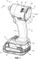
- FIG. 1 illustrates an embodiment of a power tool 10 in the form of a rotary impact tool, and, more specifically, an impact driver.
- the power tool 10 includes a housing 14 defined by cooperating first and second clamshell halves 18a, 18b (which may also be referred to as first and second housing portions).
- the illustrates first and second clamshell halves 18a, 18b are coupled together by a first plurality of fasteners 19 at a parting plane or seam 20 ( FIG. 2 ).
- the seam 20 is positioned along a longitudinal center plane of the power tool 10.
- the housing 14 includes a head housing portion 22 and a handle portion 26 extending downwardly from the head housing portion 22.
- the handle portion 26 is covered or surrounded by a grip portion 28.
- the illustrated head housing portion 22 further includes an end cap 30 coupled to a rear portion of the first and second clamshell halves 18a, 18b (e.g., by a second plurality of fasteners 31).
- the end cap 30 spans across both of the clamshell halves 18a, 18b.
- the end cap 30 may be integrally formed with the first and second clamshell halves 18a, 18b, such that the head housing portion 22 is defined entirely by the clamshell halves 18a, 18b.
- the power tool 10 further includes a battery 34 removably coupled to a battery receptacle 38 located at a bottom end or foot 40 of the handle portion 26.
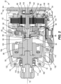
- a motor 42 (e.g., a brushless DC electric motor), a gear assembly 46, and an impact mechanism 50 are enclosed within the head housing portion 22. Stated another way, the motor 42, the gear assembly 46, and the impact mechanism 50 are enclosed within the clamshell halves 18a, 18b and the end cap 30.
- the motor 42 includes a stator 54 and a rotor 58.
- the stator 54 is directly supported by the clamshell halves 18a, 18b.
- the stator 54 may include, for example, a stator frame and a plurality of coils or windings.
- the rotor 58 includes a plurality of laminations and embedded permanent magnets, an output shaft 62, and a fan 66.
- a sensor PCB 74 which includes a plurality of sensors (e.g., Hall-effect sensors) for detecting rotation of the rotor 58, is coupled to a front side of the frame of the stator 54. In other embodiments, the sensor PCB 74 may be coupled to a rear side of the frame of the stator 54.
- the housing 14 includes vents 78a, 78b, 78c to allow airflow through the housing 14.
- the airflow is configured to cool the motor 42 and/or other electronic components (e.g., PCBs, switching electronics, etc.) within the housing 14.
- the housing 14 includes a first plurality of intake vents 78a formed in the head housing portion 22, a second plurality of intake vents 78b formed in the foot 40, and a plurality of exhaust vents 78c formed in the head housing portion 22 adjacent the end cap 30.
- rotation of the fan 66 may draw cooling air into the housing 14 through the intake vents 78a, 78b and then discharge the cooling air through the exhaust vents 78c.
- the gear assembly 46 includes a pinion 82 coupled to the output shaft 62, a plurality of planet gears 86 meshed with the pinion 82, and a ring gear 90 meshed with the planet gears 86.
- the pinion 82, planet gears 86, and the ring gear 90 may be spur gears, helical gears, or other suitable types of gears.
- the pinion 82 is rotatably supported by a front rotor bearing 94 (e.g., ball bearing).
- the front rotor bearing 94 is disposed within a cavity 100 in a camshaft 98 and includes an inner race 95 and an outer race 96.
- the inner race 95 is coupled to the pinion 82 and rotates with the pinion 82.
- the outer race 96 is coupled to the camshaft 98 and rotates with the camshaft 98.
- the inner race 95 may include lugs that are received by recesses in the pinion 82 to further secure the inner race 95 to the pinion 82.
- the pinion 82 may include lugs and the inner race 95 may include recesses to receive the lugs.
- the ring gear 90 is rotationally fixed within a recess 102 in the head housing portion 22. Stated another way, the ring gear 90 is directly supported by the clamshell halves 18a, 18b.
- the ring gear 90 may include lugs that are received in additional recesses or grooves within the head housing portion 22 to further fix the ring gear 90 within the head housing portion 22.
- the planet gears 86 are coupled to the camshaft 98 of the impact mechanism 50 such that the camshaft 98 acts as a planet carrier. Accordingly, rotation of the output shaft 62 rotates the planet gears 86, which then advance along the inner circumference of the ring gear 90 and thereby rotate the camshaft 98.
- the impact mechanism 50 further includes a hammer 106 supported on and axially slidable relative to the camshaft 98, a spring 110 partially disposed within the hammer 106 and configured to bias the hammer 106 along the axis 70 toward a front side of the power tool 10, and an anvil 114 (which may also be referred to as an output member).
- the hammer 106 is configured to reciprocate axially along the camshaft 98 to impart rotational impacts to the anvil 114 in response to rotation of the camshaft 98.
- the anvil 114 is rotationally supported for rotation about the axis 70 by an output member support or anvil support, which in the illustrated embodiment includes a bearing 118 (also referred to as an anvil bearing 118).
- the anvil bearing 118 is held within a recess 122 defined by a front portion of the clamshell halves 18a, 18b. As such, the anvil bearing 118 is directly supported by the clamshell halves 18a, 18b.
- a bushing 126 is received in the recess 122 adjacent a front side of the anvil bearing 118.
- the bushing 126 (also directly supported by the clamshell halves 18a, 18b), abuts the anvil bearing 118 to secure and resist movement of the anvil bearing 118 along the axis 70.
- the anvil 114 may additionally or alternatively be rotationally supported by the bushing 126.
- the anvil 114 may be rotationally supported by multiple bearings or multiple bushings.
- the anvil support may include one or more bushings or bearings.
- the anvil support may be insert-molded within the housing 14.
- the anvil support may be an integral portion of the clamshell halves 18a, 18b.
- the clamshell halves 18a, 18b may collectively define a bearing surface directly supported by the remainder of the clamshell halves 18a, 18b and configured to rotationally support the anvil 114.
- the head housing portion 22 defines a chamber that encloses the gear assembly 46 and the impact mechanism 50.
- the chamber is at least partially sealed by sealing elements 132 which are made of a flexible/semi-flexible material (e.g., rubber, neoprene, silicone, or the like).
- the sealing elements 132 may be disposed within corresponding grooves in each of the clamshell halves 18a, 18b and may optionally be insert-molded within the clamshell halves 18a, 18b.
- the sealing elements 132 inhibit grease, oil, or the like that may be used to lubricate the gear assembly 46 and the impact mechanism 50 from escaping from the chamber.
- the chamber is bounded at its rear side by a dividing wall 134.
- the dividing wall 134 is arranged between the motor 42 and the gear assembly 46.
- one or more additional sealing elements e.g., gaskets, o-rings, etc. may seal between the dividing wall 134 and the clamshell halves 18a, 18b.
- the end cap 30 includes a post 138 extending from a body of the end cap 30 toward the front side of the power tool 10 along the axis 70.
- the post 138 is integrally formed as a single piece with the remainder of the end cap 30.
- the post 138 is received within a bearing 142 (also referred to as a rear rotor bearing 142).
- the rear rotor bearing 142 includes an inner race 143 and an outer race 144.
- the post 138 contacts the inner race 143. More specifically, the inner race 143 is fixedly coupled to the post 138, such that the inner race 143 may not rotate.
- the outer race 144 is received within and coupled to the fan 66.
- the rear rotor bearing 142 is configured to support the fan 66, and the outer race 144 rotates with the fan 66 during operation.
- the fan 66 supports the output shaft 62, which in turn supports the rotor 58.
- the rear rotor bearing 142 supports a rear end portion of a rotor assembly, the rotor assembly comprising the rotor 58, output shaft 62 and fan 66.
- the rear rotor bearing 142 may include lugs or apertures on the inner race 143 and/or the outer race 144 that engage with lugs or apertures on the respective surfaces contacted by the inner race 143 and the outer race 144.
- a rear surface of the rear rotor bearing 142 is flush with a rear surface of the fan 66. Stated another way, the entire rear rotor bearing 142 is disposed within the fan 66. This provides for a more compact length of the power tool 10 along the axis 70. In other embodiments, however, the rear rotor bearing 142 may be only partially recessed within the fan 66.
- a front side (or inner side) of the illustrated end cap 30 includes a support member 148 that contacts the clamshell halves 18a, 18b to further secure the end cap 30 to the clamshell halves 18a, 18b ( FIG. 2 ).
- the support member 148 is an annular ring.
- the support member 148 may include a plurality of independent projections that contact the clamshell halves 18a, 18b.
- the body of the end cap 30 has a width W measured parallel to the axis 70.
- the width W is about 3 mm or less.
- the width W is between 2.5 mm and 3 mm.
- the end cap 30 may have another width W.
- the relatively thin width of the end cap 30 in the illustrated embodiment allows for the power tool 10 to have a very compact length along the axis 70.
- the end cap 30 includes a generally flat rear surface 152 on a side of the end cap 30 opposite the clamshell halves 18a, 18b.
- the rear surface 152 of the end cap 30 is generally circular in the illustrated embodiment.
- the end cap 30 further includes a plurality of ears 156 extending from the end cap 30 in a direction away from the axis 70.
- the ears 156 are shaped to provide support to the portion of the end cap 30 receiving the fasteners 31.
- the ears 156 are offset from the rear surface 152, such that the ears 156 are not on a plane defined by the rear surface 152 ( FIG. 1 ).
- the ears 156 are offset from the rear surface 152 in a direction along the axis 70 toward the front side of the power tool 10.
- the end cap 30 is made of the same material as the clamshell halves 18a, 18b (e.g., a polymer material, including but not limited to Nylon-66, ABS, a fiber-reinforced polymer material, or a glass-reinforced polymer material).
- the end cap 30 may be made of a higher strength material (e.g., steel, carbon fiber reinforced nylon, etc.) than the remainder of the housing 14 to allow for sufficient strength to securely support the rear rotor bearing 142 while maintaining a thin width W.
- the seam 20 between the first clamshell half 18a and the second clamshell half 18b extends along a circular front face 160 of the head housing portion 22.
- Two of the plurality of fasteners 19 are disposed in cutouts 164 in the front face 160 and extend from the first clamshell half 18a to the second clamshell half 18b.
- the anvil 114 projects through the front face 160 ( FIG. 2 ) and is configured to be attached to and/or drive a tool bit.
- the anvil 114 is illustrated as being concentric with the front face 160 and between the two of the plurality of fastener 19.
- the illustrated clamshell halves 18a, 18b are independent components that are coupled together to form a majority of the external surface of the power tool 10.
- the clamshell halves 18a, 18b may be molded (e.g., blow molded, injection molded, etc.) out of a polymer material.
- the clamshell halves 18a, 18b and the end cap 30 define the head housing portion 22.
- the clamshell halves 18a, 18b can define the head housing portion 22.
- the clamshell halves 18a, 18b provide sufficient rigidity and support for the operation of the motor 42, the gear assembly 46, and impact mechanism 50, which prevents the need for an additional gear case or front housing portion.
- the lack of a separate gear case allows the power tool 10 to be more compact and lightweight than power tools having a separate gear case.
- Gear cases are often made with metal, which is relatively heavy compared to the polymer material of the clamshell halves 18a, 18b.
- the lack of the gear case also decreases the total number of parts needed for the power tool 10 and may simplify manufacturing.
- FIG. 5 illustrates another end cap 230 for use with the power tool 10.
- the illustrated end cap 230 includes an insert 234 molded (e.g., insert-molded) within a body of the end cap 230.
- the insert 234 is made of a material different than the material of the end cap 230.
- the insert 234 is made of a high-strength material (e.g., steel, carbon fiber tape, carbon fiber sheet, etc.) that is relatively stronger than the material of the body of the end cap 230.
- the illustrated insert 234 includes a post 238 extending from the end cap 230 toward the front side of the power tool 10 along the axis 70 and into the rear rotor bearing 142.
- the post 238 is coupled to the inner race 143, such that the post 238 supports the inner race 143.
- the inner race 143 may be press-fit to the post 238 or secured to the post 238 in any other suitable manner.
- the insert 234 also includes an insert support 242 extending radially from the post 238 within the end cap 230.
- the insert support 242 is configured to stabilize the insert 234 within the end cap 230.
- the insert support 242 is a generally circular disc.
- the insert support 242 may be a plurality of projections.
- the rear surface of the rear rotor bearing 142 is flush with the rear surface of the fan 66.
- the end cap 230 may include one or more exhaust openings 246 for discharging cooling air moved by the fan 66.
- the end cap 230 may also include a grip portion 250.
- power tool 10 is described and illustrated herein as an impact tool; however, in other embodiments, the integrated gear case may be incorporated into other types of power tools, including continuous torque tools such as drills, powered screwdrivers, and the like.
- the anvil 114 may be replaced by a spindle or other output member driven by the motor.
Landscapes
- Engineering & Computer Science (AREA)
- Mechanical Engineering (AREA)
- Percussive Tools And Related Accessories (AREA)
- Portable Power Tools In General (AREA)
Abstract
Description
- This application claims priority to
U.S. Provisional Patent Application No. 63/384,519, filed on November 21, 2022 U.S. Provisional Patent Application No. 63/384,522, filed on November 21, 2022 - The present disclosure relates to power tools, and to power tools having a case enclosing a gear assembly, impact assembly, or the like.
- Power tools with gear assemblies, impact assemblies, and the like typically include a gear case, which may also be referred to as an impact case or front housing, to enclose and support such assemblies. The gear case is typically a separate component coupled to a main housing (e.g., clamshell housing) of the power tool.
- In some aspects, the techniques described herein relate to a power tool including: a housing including first and second clamshell halves; a motor directly supported by the first and second clamshell halves; a gear assembly directly supported by the first and second clamshell halves and operably coupled to the motor; and an impact mechanism disposed within the housing between the first and second clamshell halves and operably coupled to the gear assembly, the impact mechanism including a camshaft, an anvil rotationally supported by an anvil support for rotation about an axis, the anvil support being directly supported by the first and second clamshell halves, and a hammer configured to reciprocate along the camshaft and to impart rotational impacts to the anvil in response to rotation of the camshaft.
- In some aspects, the techniques described herein relate to a power tool, wherein a seam defined between the first and second clamshell halves extends along a front face of the housing.
- In some aspects, the techniques described herein relate to a power tool, wherein the anvil extends through the front face of the housing.
- In some aspects, the techniques described herein relate to a power tool, wherein the anvil support includes a bearing or a bushing disposed in a recess of the housing.
- In some aspects, the techniques described herein related to a power tool, wherein the anvil support is an integral portion of the housing.
- In some aspects, the techniques described herein relate to a power tool, wherein the housing includes a sealed chamber enclosing the gear assembly and the impact mechanism.
- In some aspects, the techniques described herein relate to a power tool, wherein the sealed chamber is sealed by sealing elements disposed in the housing.
- In some aspects, the techniques described herein relate to a power tool, wherein the sealed chamber is bounded by a wall positioned between the motor and the gear assembly.
- In some aspects, the techniques described herein relate to a power tool, wherein the gear assembly includes a pinion coupled to the motor, a plurality of planet gears meshed with the pinion and coupled to the camshaft, and a ring gear meshed with the plurality of planet gears and directly supported by the first and second clamshell halves.
- In some aspects, the techniques described herein relate to a power tool, wherein the housing further includes an end cap coupled to the first and second clamshell halves.
- In some aspects, the techniques described herein relate to a power tool, wherein the first and second clamshell halves and a body of the end cap are made of a polymer material.
- In some aspects, the techniques described herein relate to a power tool, wherein the end cap includes an insert made of a material different than the polymer material.
- In some aspects, the techniques described herein relate to a power tool including: a housing including first and second clamshell halves; a motor directly supported by the first and second clamshell halves; and an output member extending from the housing, the output member configured to be driven by the motor to drive a tool bit, wherein the output member is rotationally supported by an output member support for rotation about an axis, and wherein the output member support is directly supported by the first and second clamshell halves.
- In some aspects, the techniques described herein relate to a power tool, wherein the motor includes a stator and a rotor, the rotor includes a fan, the rotor is rotationally supported by a rotor bearing having an inner race and an outer race, the housing includes an end cap coupled to the first and second clamshell halves, the end cap includes a post supporting the inner race of the rotor bearing, and the outer race of the rotor bearing is received within the fan.
- In some aspects, the techniques described herein relate to a power tool including: a housing including first and second clamshell halves and an end cap coupled to the first and second clamshell halves, the end cap including a post; a motor including a stator supported by the first and second clamshell halves and a rotor rotationally supported by a rotor bearing; and an output member extending from the housing, the output member configured to be driven by the motor to drive a tool bit, wherein the post of the end cap supports an inner race of the rotor bearing.
- In some aspects, the techniques described herein relate to a power tool, wherein the rotor includes a fan, and wherein the rotor bearing includes an outer race received within the fan.
- In some aspects, the techniques described herein relate to a power tool, wherein a rear surface of the rotor bearing is flush with a rear surface of the fan.
- In some aspects, the techniques described herein relate to a power tool, wherein the end cap includes a body and an insert molded within the end cap, and wherein the insert includes the post.
- In some aspects, the techniques described herein relate to a power tool, wherein the body of the end cap is made of a polymer material, and wherein the insert is made of a material different than the polymer material.
- In some aspects, the techniques described herein relate to a power tool, wherein the first and second clamshell halves are made of the polymer material.
- In some aspects, the techniques described herein relate to a power tool, wherein the post is integrally formed as a single piece with a remainder of the end cap.
- In some aspects, the techniques described herein relate to a power tool comprising:
- a housing including first and second clamshell halves;
- a motor directly supported by the first and second clamshell halves;
- a gear assembly directly supported by the first and second clamshell halves and operably coupled to the motor; and
- an impact mechanism disposed within the housing between the first and second clamshell halves and operably coupled to the gear assembly, the impact mechanism including
a camshaft, - an anvil rotationally supported by an anvil support for rotation about an axis, the anvil support being directly supported by the first and second clamshell halves, and
- A seam defined between the first and second clamshell halves may extend along a front face of the housing.
- The anvil may extend through the front face of the housing.
- The anvil support may include a bearing or a bushing disposed in a recess of the housing.
- The anvil support may be an integral portion of the housing.
- The housing may include a sealed chamber enclosing the gear assembly and the impact mechanism.
- The sealed chamber may be sealed by sealing elements disposed in the housing.
- The sealed chamber may be bounded by a wall positioned between the motor and the gear assembly.
- The gear assembly may include
- a pinion coupled to the motor,
- a plurality of planet gears meshed with the pinion and coupled to the camshaft, and
- a ring gear meshed with the plurality of planet gears and directly supported by the first and second clamshell halves.
- The housing may further include an end cap coupled to the first and second clamshell halves.
- The first and second clamshell halves and a body of the end cap may be made of a polymer material.
- The end cap may include an insert made of a material different than the polymer material.
- In some aspects, the techniques described herein relate to a power tool comprising:
- a housing including first and second clamshell halves;
- a motor directly supported by the first and second clamshell halves; and
- an output member extending from the housing, the output member configured to be driven by the motor to drive a tool bit,
- wherein the output member is rotationally supported by an output member support for rotation about an axis, and
- wherein the output member support is directly supported by the first and second clamshell halves.
- The motor may include a stator and a rotor,
- the rotor may include a fan,
- the rotor may be rotationally supported by a rotor bearing having an inner race and an outer race,
- the housing may include an end cap coupled to the first and second clamshell halves,
- the end cap may include a post supporting the inner race of the rotor bearing, and
- the outer race of the rotor bearing may be received within the fan.
- In some aspects, the techniques described herein relate to a power tool comprising:
- a housing including first and second clamshell halves and an end cap coupled to the first and second clamshell halves, the end cap including a post;
- a motor including a stator supported by the first and second clamshell halves and a rotor rotationally supported by a rotor bearing; and
- an output member extending from the housing, the output member configured to be driven by the motor to drive a tool bit,
- wherein the post of the end cap supports an inner race of the rotor bearing.
- The rotor may include a fan, and wherein the rotor bearing includes an outer race received within the fan.
- A rear surface of the rotor bearing may be flush with a rear surface of the fan.
- The end cap may include a body and an insert molded within the end cap, and wherein the insert may include the post.
- The body of the end cap may be made of a polymer material, and wherein the insert may be made of a material different than the polymer material.
- The first and second clamshell halves may be made of the polymer material.
- wherein the post is integrally formed as a single piece with a remainder of the end cap.
- Other features and aspects of the disclosure will become apparent by consideration of the following detailed description and accompanying drawings.
-
-
FIG. 1 is a perspective view of a power tool according to an embodiment of the present disclosure. -
FIG. 2 is a cross-sectional view of a portion of the power tool ofFIG. 1 , taken along line 2-2 inFIG. 1 . -
FIG. 3 is a rear view of a portion of the power tool ofFIG. 1 , illustrating an end cap of the power tool. -
FIG. 4 is a front view of a portion of the power tool ofFIG. 1 . -
FIG. 5 is a cross-sectional view of a portion of the power tool ofFIG. 1 , including an end cap according to another embodiment. - Before any embodiments of the disclosure are explained in detail, it is to be understood that the disclosure is not limited in its application to the details of construction and the arrangement of components set forth in the following description or illustrated in the following drawings. The disclosure is capable of other embodiments and of being practiced or of being carried out in various ways. Also, it is to be understood that the phraseology and terminology used herein is for the purpose of description and should not be regarded as limiting.
-
FIG. 1 illustrates an embodiment of apower tool 10 in the form of a rotary impact tool, and, more specifically, an impact driver. Thepower tool 10 includes ahousing 14 defined by cooperating first andsecond clamshell halves second clamshell halves fasteners 19 at a parting plane or seam 20 (FIG. 2 ). In the illustrated embodiment, theseam 20 is positioned along a longitudinal center plane of thepower tool 10. Thehousing 14 includes ahead housing portion 22 and ahandle portion 26 extending downwardly from thehead housing portion 22. In the illustrated embodiment, thehandle portion 26 is covered or surrounded by agrip portion 28. The illustratedhead housing portion 22 further includes anend cap 30 coupled to a rear portion of the first andsecond clamshell halves end cap 30 spans across both of theclamshell halves end cap 30 may be integrally formed with the first andsecond clamshell halves head housing portion 22 is defined entirely by theclamshell halves power tool 10 further includes abattery 34 removably coupled to abattery receptacle 38 located at a bottom end orfoot 40 of thehandle portion 26. - With reference to
FIG. 2 , a motor 42 (e.g., a brushless DC electric motor), agear assembly 46, and animpact mechanism 50 are enclosed within thehead housing portion 22. Stated another way, themotor 42, thegear assembly 46, and theimpact mechanism 50 are enclosed within theclamshell halves end cap 30. Themotor 42 includes astator 54 and arotor 58. Thestator 54 is directly supported by theclamshell halves stator 54 may include, for example, a stator frame and a plurality of coils or windings. Therotor 58 includes a plurality of laminations and embedded permanent magnets, anoutput shaft 62, and afan 66. Theoutput shaft 62 and thefan 66 are coupled for co-rotation with therotor 58 about anaxis 70 relative to thestator 54. Asensor PCB 74, which includes a plurality of sensors (e.g., Hall-effect sensors) for detecting rotation of therotor 58, is coupled to a front side of the frame of thestator 54. In other embodiments, thesensor PCB 74 may be coupled to a rear side of the frame of thestator 54. - With returned reference to
FIG. 1 , thehousing 14 includesvents housing 14. The airflow is configured to cool themotor 42 and/or other electronic components (e.g., PCBs, switching electronics, etc.) within thehousing 14. In the illustrated embodiment, thehousing 14 includes a first plurality ofintake vents 78a formed in thehead housing portion 22, a second plurality ofintake vents 78b formed in thefoot 40, and a plurality ofexhaust vents 78c formed in thehead housing portion 22 adjacent theend cap 30. During operation, rotation of thefan 66 may draw cooling air into thehousing 14 through theintake vents - With returned reference to
FIG. 2 , in the illustrated embodiment, thegear assembly 46 includes apinion 82 coupled to theoutput shaft 62, a plurality of planet gears 86 meshed with thepinion 82, and aring gear 90 meshed with the planet gears 86. In some embodiments, thepinion 82, planet gears 86, and thering gear 90 may be spur gears, helical gears, or other suitable types of gears. Thepinion 82 is rotatably supported by a front rotor bearing 94 (e.g., ball bearing). The front rotor bearing 94 is disposed within acavity 100 in acamshaft 98 and includes aninner race 95 and anouter race 96. Theinner race 95 is coupled to thepinion 82 and rotates with thepinion 82. Theouter race 96 is coupled to thecamshaft 98 and rotates with thecamshaft 98. In some embodiments, theinner race 95 may include lugs that are received by recesses in thepinion 82 to further secure theinner race 95 to thepinion 82. In other embodiments, thepinion 82 may include lugs and theinner race 95 may include recesses to receive the lugs. Thering gear 90 is rotationally fixed within arecess 102 in thehead housing portion 22. Stated another way, thering gear 90 is directly supported by theclamshell halves ring gear 90 may include lugs that are received in additional recesses or grooves within thehead housing portion 22 to further fix thering gear 90 within thehead housing portion 22. - With continued reference to
FIG. 2 , the planet gears 86 are coupled to thecamshaft 98 of theimpact mechanism 50 such that thecamshaft 98 acts as a planet carrier. Accordingly, rotation of theoutput shaft 62 rotates the planet gears 86, which then advance along the inner circumference of thering gear 90 and thereby rotate thecamshaft 98. Theimpact mechanism 50 further includes ahammer 106 supported on and axially slidable relative to thecamshaft 98, aspring 110 partially disposed within thehammer 106 and configured to bias thehammer 106 along theaxis 70 toward a front side of thepower tool 10, and an anvil 114 (which may also be referred to as an output member). Thehammer 106 is configured to reciprocate axially along thecamshaft 98 to impart rotational impacts to theanvil 114 in response to rotation of thecamshaft 98. Theanvil 114 is rotationally supported for rotation about theaxis 70 by an output member support or anvil support, which in the illustrated embodiment includes a bearing 118 (also referred to as an anvil bearing 118). Theanvil bearing 118 is held within arecess 122 defined by a front portion of theclamshell halves anvil bearing 118 is directly supported by theclamshell halves bushing 126 is received in therecess 122 adjacent a front side of theanvil bearing 118. Thebushing 126, (also directly supported by theclamshell halves axis 70. In some embodiments, theanvil 114 may additionally or alternatively be rotationally supported by thebushing 126. In some embodiments, theanvil 114 may be rotationally supported by multiple bearings or multiple bushings. As such, the anvil support may include one or more bushings or bearings. In some embodiments, the anvil support may be insert-molded within thehousing 14. In yet other embodiments, the anvil support may be an integral portion of theclamshell halves clamshell halves clamshell halves anvil 114. - With continued reference to
FIG. 2 , thehead housing portion 22 defines a chamber that encloses thegear assembly 46 and theimpact mechanism 50. The chamber is at least partially sealed by sealingelements 132 which are made of a flexible/semi-flexible material (e.g., rubber, neoprene, silicone, or the like). The sealingelements 132 may be disposed within corresponding grooves in each of theclamshell halves clamshell halves elements 132 inhibit grease, oil, or the like that may be used to lubricate thegear assembly 46 and theimpact mechanism 50 from escaping from the chamber. In the illustrated embodiment, the chamber is bounded at its rear side by a dividingwall 134. The dividingwall 134 is arranged between themotor 42 and thegear assembly 46. In some embodiments, one or more additional sealing elements (e.g., gaskets, o-rings, etc.) may seal between the dividingwall 134 and theclamshell halves - With continued reference to
FIG. 2 , theend cap 30 includes apost 138 extending from a body of theend cap 30 toward the front side of thepower tool 10 along theaxis 70. In the illustrated embodiment, thepost 138 is integrally formed as a single piece with the remainder of theend cap 30. Thepost 138 is received within a bearing 142 (also referred to as a rear rotor bearing 142). The rear rotor bearing 142 includes aninner race 143 and anouter race 144. Thepost 138 contacts theinner race 143. More specifically, theinner race 143 is fixedly coupled to thepost 138, such that theinner race 143 may not rotate. Theouter race 144 is received within and coupled to thefan 66. The rear rotor bearing 142 is configured to support thefan 66, and theouter race 144 rotates with thefan 66 during operation. Thefan 66 supports theoutput shaft 62, which in turn supports therotor 58. Thus, the rear rotor bearing 142 supports a rear end portion of a rotor assembly, the rotor assembly comprising therotor 58,output shaft 62 andfan 66. Similar to the front rotor bearing 94, in some embodiments, the rear rotor bearing 142 may include lugs or apertures on theinner race 143 and/or theouter race 144 that engage with lugs or apertures on the respective surfaces contacted by theinner race 143 and theouter race 144. In the illustrated embodiment, a rear surface of the rear rotor bearing 142 is flush with a rear surface of thefan 66. Stated another way, the entire rear rotor bearing 142 is disposed within thefan 66. This provides for a more compact length of thepower tool 10 along theaxis 70. In other embodiments, however, the rear rotor bearing 142 may be only partially recessed within thefan 66. - A front side (or inner side) of the
illustrated end cap 30 includes asupport member 148 that contacts theclamshell halves end cap 30 to theclamshell halves FIG. 2 ). In some embodiments, thesupport member 148 is an annular ring. In other embodiments, thesupport member 148 may include a plurality of independent projections that contact theclamshell halves - With continued reference to
FIG. 2 , the body of theend cap 30 has a width W measured parallel to theaxis 70. In some embodiments, the width W is about 3 mm or less. In some embodiments, the width W is between 2.5 mm and 3 mm. In other embodiments, theend cap 30 may have another width W. The relatively thin width of theend cap 30 in the illustrated embodiment allows for thepower tool 10 to have a very compact length along theaxis 70. - Best illustrated in
FIG. 3 , theend cap 30 includes a generally flatrear surface 152 on a side of theend cap 30 opposite theclamshell halves rear surface 152 of theend cap 30 is generally circular in the illustrated embodiment. Theend cap 30 further includes a plurality ofears 156 extending from theend cap 30 in a direction away from theaxis 70. Theears 156 are shaped to provide support to the portion of theend cap 30 receiving thefasteners 31. In the illustrated embodiment, theears 156 are offset from therear surface 152, such that theears 156 are not on a plane defined by the rear surface 152 (FIG. 1 ). In other words, theears 156 are offset from therear surface 152 in a direction along theaxis 70 toward the front side of thepower tool 10. - In the illustrated embodiment, the
end cap 30 is made of the same material as theclamshell halves end cap 30 may be made of a higher strength material (e.g., steel, carbon fiber reinforced nylon, etc.) than the remainder of thehousing 14 to allow for sufficient strength to securely support the rear rotor bearing 142 while maintaining a thin width W. - As illustrated in
FIG. 4 , theseam 20 between thefirst clamshell half 18a and thesecond clamshell half 18b extends along a circularfront face 160 of thehead housing portion 22. Two of the plurality offasteners 19 are disposed incutouts 164 in thefront face 160 and extend from thefirst clamshell half 18a to thesecond clamshell half 18b. Theanvil 114 projects through the front face 160 (FIG. 2 ) and is configured to be attached to and/or drive a tool bit. Theanvil 114 is illustrated as being concentric with thefront face 160 and between the two of the plurality offastener 19. - With reference to
FIGS. 1 , the illustratedclamshell halves power tool 10. The clamshell halves 18a, 18b may be molded (e.g., blow molded, injection molded, etc.) out of a polymer material. In some embodiments, theclamshell halves end cap 30 define thehead housing portion 22. In other embodiments without an end cap, theclamshell halves head housing portion 22. The clamshell halves 18a, 18b provide sufficient rigidity and support for the operation of themotor 42, thegear assembly 46, andimpact mechanism 50, which prevents the need for an additional gear case or front housing portion. The lack of a separate gear case allows thepower tool 10 to be more compact and lightweight than power tools having a separate gear case. Gear cases are often made with metal, which is relatively heavy compared to the polymer material of theclamshell halves power tool 10 and may simplify manufacturing. -
FIG. 5 illustrates anotherend cap 230 for use with thepower tool 10. Theillustrated end cap 230 includes aninsert 234 molded (e.g., insert-molded) within a body of theend cap 230. In the illustrated embodiment, theinsert 234 is made of a material different than the material of theend cap 230. For example, theinsert 234 is made of a high-strength material (e.g., steel, carbon fiber tape, carbon fiber sheet, etc.) that is relatively stronger than the material of the body of theend cap 230. The illustratedinsert 234 includes apost 238 extending from theend cap 230 toward the front side of thepower tool 10 along theaxis 70 and into therear rotor bearing 142. Thepost 238 is coupled to theinner race 143, such that thepost 238 supports theinner race 143. Theinner race 143 may be press-fit to thepost 238 or secured to thepost 238 in any other suitable manner. Theinsert 234 also includes aninsert support 242 extending radially from thepost 238 within theend cap 230. Theinsert support 242 is configured to stabilize theinsert 234 within theend cap 230. In some embodiments, theinsert support 242 is a generally circular disc. In other embodiments, theinsert support 242 may be a plurality of projections. In the illustrated embodiment, the rear surface of the rear rotor bearing 142 is flush with the rear surface of thefan 66. Theend cap 230 may include one ormore exhaust openings 246 for discharging cooling air moved by thefan 66. Theend cap 230 may also include agrip portion 250. - Although the disclosure has been described in detail with reference to certain preferred embodiments, variations and modifications exist within the scope and spirit of one or more independent aspects of the disclosure as described. For example,
power tool 10 is described and illustrated herein as an impact tool; however, in other embodiments, the integrated gear case may be incorporated into other types of power tools, including continuous torque tools such as drills, powered screwdrivers, and the like. In such embodiments, theanvil 114 may be replaced by a spindle or other output member driven by the motor. - Various features of the disclosure are set forth in the following claims. When used in this specification and claims, the terms "comprises" and "comprising" and variations thereof mean that the specified features, steps or integers are included. The terms are not to be interpreted to exclude the presence of other features, steps or components.
- Representative features are set out in the following clauses, which stand alone or may be combined, in any combination, with one or more features disclosed in the text and/or drawings of the specification.
- 1. A power tool comprising:
- a housing including first and second clamshell halves;
- a motor directly supported by the first and second clamshell halves;
- a gear assembly directly supported by the first and second clamshell halves and operably coupled to the motor; and
- an impact mechanism disposed within the housing between the first and second clamshell halves and operably coupled to the gear assembly, the impact mechanism including
a camshaft, - an anvil rotationally supported by an anvil support for rotation about an axis, the anvil support being directly supported by the first and second clamshell halves, and
- 2. The power tool of clause 1, wherein a seam defined between the first and second clamshell halves extends along a front face of the housing.
- 3. The power tool of
clause 2, wherein the anvil extends through the front face of the housing. - 4. The power tool of clause 1, wherein the anvil support includes a bearing or a bushing disposed in a recess of the housing.
- 5. The power tool of clause 1, wherein the housing includes a sealed chamber enclosing the gear assembly and the impact mechanism.
- 6. The power tool of clause 5, wherein the sealed chamber is bounded by a wall positioned between the motor and the gear assembly.
- 7. The power tool of clause 1, wherein the anvil support is an integral portion of the housing.
- 8. The power tool of clause 1, wherein the gear assembly includes
- a pinion coupled to the motor,
- a plurality of planet gears meshed with the pinion and coupled to the camshaft, and
- a ring gear meshed with the plurality of planet gears and directly supported by the first and second clamshell halves.
- 9. The power tool of clause 1, wherein the housing further includes an end cap coupled to the first and second clamshell halves.
- 10. The power tool of clause 9, wherein the first and second clamshell halves and a body of the end cap are made of a polymer material.
- 11. The power tool of
clause 10, wherein the end cap includes an insert made of a material different than the polymer material. - 12. A power tool comprising:
- a housing including first and second clamshell halves;
- a motor directly supported by the first and second clamshell halves; and
- an output member extending from the housing, the output member configured to be driven by the motor to drive a tool bit,
- wherein the output member is rotationally supported by an output member support for rotation about an axis, and
- wherein the output member support is directly supported by the first and second clamshell halves.
- 13. The power tool of clause 12, wherein
- the motor includes a stator and a rotor,
- the rotor includes a fan,
- the rotor is rotationally supported by a rotor bearing having an inner race and an outer race,
- the housing includes an end cap coupled to the first and second clamshell halves,
- the end cap includes a post supporting the inner race of the rotor bearing, and
- the outer race of the rotor bearing is received within the fan.
- 14. A power tool comprising:
- a housing including first and second clamshell halves and an end cap coupled to the first and second clamshell halves, the end cap including a post;
- a motor including a stator supported by the first and second clamshell halves and a rotor rotationally supported by a rotor bearing; and
- an output member extending from the housing, the output member configured to be driven by the motor to drive a tool bit,
- wherein the post of the end cap supports an inner race of the rotor bearing.
- 15. The power tool of
clause 14, wherein the rotor includes a fan, and wherein the rotor bearing includes an outer race received within the fan. - 16. The power tool of clause 15, wherein a rear surface of the rotor bearing is flush with a rear surface of the fan.
- 17. The power tool of
clause 14, wherein the end cap includes a body and an insert molded within the end cap, and wherein the insert includes the post. - 18. The power tool of clause 17, wherein the body of the end cap is made of a polymer material, and wherein the insert is made of a material different than the polymer material.
- 19. The power tool of clause 18, wherein the first and second clamshell halves are made of the polymer material.
- 20. The power tool of
clause 14, wherein the post is integrally formed as a single piece with a remainder of the end cap.
Claims (15)
- A power tool comprising:a housing including first and second clamshell halves;a motor directly supported by the first and second clamshell halves;a gear assembly directly supported by the first and second clamshell halves and operably coupled to the motor; andan impact mechanism disposed within the housing between the first and second clamshell halves and operably coupled to the gear assembly, the impact mechanism including
a camshaft,an anvil rotationally supported by an anvil support for rotation about an axis, the anvil support being directly supported by the first and second clamshell halves, anda hammer configured to reciprocate along the camshaft and to impart rotational impacts to the anvil in response to rotation of the camshaft. - The power tool of claim 1, wherein a seam defined between the first and second clamshell halves extends along a front face of the housing.
- The power tool of claim 1 or 2, wherein the anvil extends through the front face of the housing.
- The power tool of any preceding claim, wherein the anvil support includes a bearing or a bushing disposed in a recess of the housing.
- The power tool of claim 1, wherein the anvil support is an integral portion of the housing.
- The power tool of claim 5, wherein the housing includes a sealed chamber enclosing the gear assembly and the impact mechanism,
and, optionally
wherein the sealed chamber is sealed by sealing elements disposed in the housing and/or wherein the sealed chamber is bounded by a wall positioned between the motor and the gear assembly. - The power tool of any preceding claim, wherein the gear assembly includesa pinion coupled to the motor,a plurality of planet gears meshed with the pinion and coupled to the camshaft, anda ring gear meshed with the plurality of planet gears and directly supported by the first and second clamshell halves.
- The power tool of any preceding claim, wherein the housing further includes an end cap coupled to the first and second clamshell halves.
- The power tool of claim 8, wherein the first and second clamshell halves and a body of the end cap are made of a polymer material, preferably wherein the end cap includes an insert made of a material different than the polymer material.
- A power tool comprising:a housing including first and second clamshell halves;a motor directly supported by the first and second clamshell halves; andan output member extending from the housing, the output member configured to be driven by the motor to drive a tool bit,wherein the output member is rotationally supported by an output member support for rotation about an axis, andwherein the output member support is directly supported by the first and second clamshell halves.
- The power tool of claim 10, whereinthe motor includes a stator and a rotor,the rotor includes a fan,the rotor is rotationally supported by a rotor bearing having an inner race and an outer race,the housing includes an end cap coupled to the first and second clamshell halves,the end cap includes a post supporting the inner race of the rotor bearing, andthe outer race of the rotor bearing is received within the fan.
- A power tool comprising:a housing including first and second clamshell halves and an end cap coupled to the first and second clamshell halves, the end cap including a post;a motor including a stator supported by the first and second clamshell halves and a rotor rotationally supported by a rotor bearing; andan output member extending from the housing, the output member configured to be driven by the motor to drive a tool bit,wherein the post of the end cap supports an inner race of the rotor bearing.
- The power tool of claim 12, wherein the rotor includes a fan, and wherein the rotor bearing includes an outer race received within the fan, preferably wherein a rear surface of the rotor bearing is flush with a rear surface of the fan.
- The power tool of claim 12 or 13, wherein the end cap includes a body and an insert molded within the end cap, and wherein the insert includes the post, preferably wherein the body of the end cap is made of a polymer material, and wherein the insert is made of a material different than the polymer material, more preferably wherein the first and second clamshell halves are made of the polymer material.
- The power tool of claim 12, 13 or 14, wherein the post is integrally formed as a single piece with a remainder of the end cap.
Applications Claiming Priority (2)
| Application Number | Priority Date | Filing Date | Title |
|---|---|---|---|
| US202263384522P | 2022-11-21 | 2022-11-21 | |
| US202263384519P | 2022-11-21 | 2022-11-21 |
Publications (1)
| Publication Number | Publication Date |
|---|---|
| EP4410489A1 true EP4410489A1 (en) | 2024-08-07 |
Family
ID=88839429
Family Applications (1)
| Application Number | Title | Priority Date | Filing Date |
|---|---|---|---|
| EP23210763.1A Pending EP4410489A1 (en) | 2022-11-21 | 2023-11-17 | Power tool with integrated gear case |
Country Status (3)
| Country | Link |
|---|---|
| US (2) | US12533785B2 (en) |
| EP (1) | EP4410489A1 (en) |
| CN (2) | CN222079193U (en) |
Families Citing this family (1)
| Publication number | Priority date | Publication date | Assignee | Title |
|---|---|---|---|---|
| TWM670521U (en) * | 2024-08-08 | 2025-05-21 | 鑽全實業股份有限公司 | Shock-absorbing housing for power tools |
Citations (9)
| Publication number | Priority date | Publication date | Assignee | Title |
|---|---|---|---|---|
| US20170203418A1 (en) * | 2012-12-27 | 2017-07-20 | Makita Corporation | Impact tool |
| DE102017109598A1 (en) * | 2016-05-13 | 2017-11-16 | Makita Corporation | power tool |
| US10478950B2 (en) * | 2015-11-26 | 2019-11-19 | Makita Corporation | Power tool |
| DE102020104295A1 (en) * | 2019-02-21 | 2020-08-27 | Makita Corporation | Power tool |
| DE102020129856A1 (en) * | 2019-12-02 | 2021-06-02 | Makita Corporation | IMPACT TOOL |
| CN114670158A (en) * | 2020-12-24 | 2022-06-28 | 株式会社牧田 | electrical tools |
| CN115122281A (en) * | 2021-03-29 | 2022-09-30 | 株式会社牧田 | Impact tool |
| WO2024020476A1 (en) * | 2022-07-20 | 2024-01-25 | Milwaukee Electric Tool Corporation | Outer ring drive planetary gear assembly |
| DE112023002828T5 (en) * | 2022-06-29 | 2025-06-26 | Milwaukee Electric Tool Corporation | Rotor and fan assembly with an embedded magnet |
Family Cites Families (58)
| Publication number | Priority date | Publication date | Assignee | Title |
|---|---|---|---|---|
| US3166168A (en) | 1961-04-10 | 1965-01-19 | Ingersoll Rand Co | Impact tool torsion bar |
| US3369615A (en) | 1966-05-27 | 1968-02-20 | Black & Decker Mfg Co | Impact wrench |
| US5269733A (en) | 1992-05-18 | 1993-12-14 | Snap-On Tools Corporation | Power tool plastic gear train |
| EP0794038B1 (en) | 1996-01-08 | 1998-11-04 | Kress-elektrik GmbH + Co. Elektromotorenfabrik | Hand tool with cooling arrangement |
| US6446734B1 (en) | 1999-11-11 | 2002-09-10 | Black & Decker Inc. | Motor/handle housing and gear case mounting for portable power tool |
| US20050061524A1 (en) | 2001-01-23 | 2005-03-24 | Hagan Todd A. | Housing with functional overmold |
| MXPA03006554A (en) | 2001-01-23 | 2004-01-29 | Black & Decker Inc | Housing with functional overmold. |
| US6805207B2 (en) | 2001-01-23 | 2004-10-19 | Black & Decker Inc. | Housing with functional overmold |
| JP4645036B2 (en) | 2004-01-16 | 2011-03-09 | 日立工機株式会社 | Electric tool |
| JP4084319B2 (en) | 2004-02-23 | 2008-04-30 | リョービ株式会社 | Electric tool |
| JP4643298B2 (en) | 2005-02-14 | 2011-03-02 | 株式会社マキタ | Impact tool |
| DE502005008000D1 (en) | 2005-11-17 | 2009-10-08 | Metabowerke Gmbh | Beating electric hand tool device |
| US7980324B2 (en) | 2006-02-03 | 2011-07-19 | Black & Decker Inc. | Housing and gearbox for drill or driver |
| DE102006020172A1 (en) | 2006-05-02 | 2007-11-08 | Robert Bosch Gmbh | Hand tool |
| CA2873139A1 (en) | 2006-05-31 | 2007-11-30 | Ingersoll-Rand Company | Structural support for power tool housings |
| SE531738C2 (en) | 2006-09-01 | 2009-07-28 | Husqvarna Ab | Drilling machine |
| EP1932608B1 (en) | 2006-12-15 | 2011-07-06 | Black & Decker, Inc. | Drill/Driver |
| JP5073449B2 (en) | 2007-10-25 | 2012-11-14 | 株式会社マキタ | Power tool housing |
| US20090114412A1 (en) | 2007-11-05 | 2009-05-07 | Black And Decker Inc. | Power tool having housing with enhanced impact resistance |
| US20090258584A1 (en) | 2008-04-10 | 2009-10-15 | X'pole Precision Tools, Inc. | Multi-Shell Air-Tight Compartmentalized Casings |
| JP5356097B2 (en) | 2009-04-01 | 2013-12-04 | 株式会社マキタ | Impact tool |
| JP5361504B2 (en) | 2009-04-10 | 2013-12-04 | 株式会社マキタ | Impact tool |
| EP2580847B1 (en) | 2010-06-14 | 2021-11-17 | Black & Decker Inc. | Rotor assembly for brushless motor for a power tool |
| US9545713B2 (en) | 2011-06-29 | 2017-01-17 | Ingersoll-Rand Company | Power tools with housings having integral resilient motor mounts |
| US20140091648A1 (en) | 2012-10-02 | 2014-04-03 | Makita Corporation | Electric power tool |
| US9221156B2 (en) | 2013-05-15 | 2015-12-29 | Snap-On Incorporated | Motorized hand tool apparatus and assembly method |
| US9878435B2 (en) | 2013-06-12 | 2018-01-30 | Makita Corporation | Power rotary tool and impact power tool |
| JP6027946B2 (en) | 2013-06-12 | 2016-11-16 | パナソニック株式会社 | Impact wrench |
| EP2921264B1 (en) | 2014-03-20 | 2016-06-29 | Black & Decker Inc. | Hammer drill |
| US10040178B2 (en) | 2014-05-27 | 2018-08-07 | Makita Corporation | Power tool and rotary impact tool |
| JP6436744B2 (en) | 2014-11-26 | 2018-12-12 | 株式会社マキタ | Impact tools |
| US10668614B2 (en) | 2015-06-05 | 2020-06-02 | Ingersoll-Rand Industrial U.S., Inc. | Impact tools with ring gear alignment features |
| JP2017113809A (en) | 2015-12-21 | 2017-06-29 | 株式会社マキタ | Rotary tool |
| CN205438463U (en) | 2015-12-25 | 2016-08-10 | 南京德朔实业有限公司 | Power tool |
| DE102017211772A1 (en) | 2016-07-11 | 2018-01-11 | Robert Bosch Gmbh | Hand machine tool device |
| DE102017211778A1 (en) | 2016-07-11 | 2018-01-11 | Robert Bosch Gmbh | Hand machine tool device |
| JP6869739B2 (en) * | 2017-02-09 | 2021-05-12 | 株式会社マキタ | Impact tool |
| CN110382167B (en) | 2017-03-07 | 2021-11-05 | 株式会社牧田 | Tool holders and power tools, impact tools |
| JP6924692B2 (en) | 2017-12-22 | 2021-08-25 | 株式会社マキタ | Impact tool |
| JP6987667B2 (en) * | 2018-02-23 | 2022-01-05 | 株式会社マキタ | Impact tool |
| US10971966B2 (en) | 2018-05-14 | 2021-04-06 | Black & Decker Inc. | Power tool with partition assembly between transmission and motor |
| US11813729B2 (en) | 2018-05-14 | 2023-11-14 | Black & Decker Inc. | Power tool with partition assembly between transmission and motor |
| TWI658907B (en) * | 2018-05-25 | 2019-05-11 | 朝程工業股份有限公司 | Double hammer impact wrench |
| EP3846970A4 (en) | 2018-09-06 | 2022-04-06 | Techtronic Cordless GP | ROTARY IMPACT TOOLS WITH NOISE REDUCTION MECHANISM |
| US11084158B2 (en) | 2018-09-10 | 2021-08-10 | Makita Corporation | Work tool |
| JP7246202B2 (en) | 2019-02-19 | 2023-03-27 | 株式会社マキタ | Power tool with vibration mechanism |
| CN213411817U (en) | 2019-07-08 | 2021-06-11 | 苏州宝时得电动工具有限公司 | Handheld Power Tools |
| CN112238411B (en) | 2019-07-19 | 2024-02-20 | 株式会社牧田 | Electric tool and rotary tool |
| JP7356312B2 (en) * | 2019-09-30 | 2023-10-04 | 株式会社マキタ | power tools |
| CN212071751U (en) | 2019-11-25 | 2020-12-04 | 浙江开创电气股份有限公司 | Brushless electric wrench |
| WO2022004330A1 (en) | 2020-06-30 | 2022-01-06 | 工機ホールディングス株式会社 | Work machine |
| US11685036B2 (en) | 2020-07-27 | 2023-06-27 | Techtronic Cordless Gp | Motor mounting assembly for a power tool |
| US11545871B2 (en) | 2020-09-02 | 2023-01-03 | Snap-On Incorporated | Tool housing and motor exhaust management |
| JP7532200B2 (en) | 2020-10-16 | 2024-08-13 | 株式会社マキタ | Oil Pulse Tool |
| JP7664047B2 (en) * | 2021-01-06 | 2025-04-17 | 株式会社マキタ | Impact Tools |
| JP7691303B2 (en) * | 2021-08-06 | 2025-06-11 | 株式会社マキタ | Impact Tools |
| JP7744803B2 (en) * | 2021-11-24 | 2025-09-26 | 株式会社マキタ | electric work equipment |
| JP7742293B2 (en) * | 2021-12-14 | 2025-09-19 | 株式会社マキタ | Impact tools |
-
2023
- 2023-11-17 EP EP23210763.1A patent/EP4410489A1/en active Pending
- 2023-11-21 US US18/516,557 patent/US12533785B2/en active Active
- 2023-11-21 CN CN202323148344.0U patent/CN222079193U/en active Active
- 2023-11-21 CN CN202422680521.8U patent/CN223863714U/en active Active
-
2025
- 2025-12-17 US US19/423,326 patent/US20260109012A1/en active Pending
Patent Citations (9)
| Publication number | Priority date | Publication date | Assignee | Title |
|---|---|---|---|---|
| US20170203418A1 (en) * | 2012-12-27 | 2017-07-20 | Makita Corporation | Impact tool |
| US10478950B2 (en) * | 2015-11-26 | 2019-11-19 | Makita Corporation | Power tool |
| DE102017109598A1 (en) * | 2016-05-13 | 2017-11-16 | Makita Corporation | power tool |
| DE102020104295A1 (en) * | 2019-02-21 | 2020-08-27 | Makita Corporation | Power tool |
| DE102020129856A1 (en) * | 2019-12-02 | 2021-06-02 | Makita Corporation | IMPACT TOOL |
| CN114670158A (en) * | 2020-12-24 | 2022-06-28 | 株式会社牧田 | electrical tools |
| CN115122281A (en) * | 2021-03-29 | 2022-09-30 | 株式会社牧田 | Impact tool |
| DE112023002828T5 (en) * | 2022-06-29 | 2025-06-26 | Milwaukee Electric Tool Corporation | Rotor and fan assembly with an embedded magnet |
| WO2024020476A1 (en) * | 2022-07-20 | 2024-01-25 | Milwaukee Electric Tool Corporation | Outer ring drive planetary gear assembly |
Also Published As
| Publication number | Publication date |
|---|---|
| US20260109012A1 (en) | 2026-04-23 |
| CN222079193U (en) | 2024-11-29 |
| CN223863714U (en) | 2026-02-03 |
| US20240165783A1 (en) | 2024-05-23 |
| US12533785B2 (en) | 2026-01-27 |
Similar Documents
| Publication | Publication Date | Title |
|---|---|---|
| US11780061B2 (en) | Impact tool | |
| US20260109012A1 (en) | Power tool with integrated gear case | |
| US20240342874A1 (en) | Rotary impact tool | |
| US20250042004A1 (en) | Rotary impact tool | |
| US12162128B2 (en) | Power tool | |
| US11685036B2 (en) | Motor mounting assembly for a power tool | |
| EP2189246A2 (en) | Power tool | |
| US12263563B2 (en) | Compact impact tool | |
| US12415263B2 (en) | Power tool with knurled bushing | |
| US20190118352A1 (en) | Bearing retainer for a power tool | |
| US20250296217A1 (en) | Power tool with enclosed gearcase | |
| US20250050474A1 (en) | Power tool with coupling mechanism for joining first and second housing portions | |
| US12472616B2 (en) | Rotary impact tool with thrust bearing | |
| US12544883B2 (en) | Power tool with lighting assembly and wire passageway | |
| US12017313B2 (en) | Impact tool | |
| CN110815138B (en) | electrical tools | |
| US20240075608A1 (en) | Power tool with bearing retainer | |
| US20240333095A1 (en) | Electric motor and fan for a power tool | |
| WO2024006327A1 (en) | Rotor and fan assembly with an embedded magnet | |
| US20240051084A1 (en) | Die grinder with an offset gear transmission | |
| JP2024072166A (en) | Impact tool and method for manufacturing impact wrench |
Legal Events
| Date | Code | Title | Description |
|---|---|---|---|
| PUAI | Public reference made under article 153(3) epc to a published international application that has entered the european phase |
Free format text: ORIGINAL CODE: 0009012 |
|
| STAA | Information on the status of an ep patent application or granted ep patent |
Free format text: STATUS: THE APPLICATION HAS BEEN PUBLISHED |
|
| AK | Designated contracting states |
Kind code of ref document: A1 Designated state(s): AL AT BE BG CH CY CZ DE DK EE ES FI FR GB GR HR HU IE IS IT LI LT LU LV MC ME MK MT NL NO PL PT RO RS SE SI SK SM TR |
|
| STAA | Information on the status of an ep patent application or granted ep patent |
Free format text: STATUS: REQUEST FOR EXAMINATION WAS MADE |
|
| 17P | Request for examination filed |
Effective date: 20250206 |
|
| STAA | Information on the status of an ep patent application or granted ep patent |
Free format text: STATUS: EXAMINATION IS IN PROGRESS |
|
| 17Q | First examination report despatched |
Effective date: 20260410 |