EP4410468A1 - Laser machining apparatus and laser machining method - Google Patents
Laser machining apparatus and laser machining method Download PDFInfo
- Publication number
- EP4410468A1 EP4410468A1 EP22875804.1A EP22875804A EP4410468A1 EP 4410468 A1 EP4410468 A1 EP 4410468A1 EP 22875804 A EP22875804 A EP 22875804A EP 4410468 A1 EP4410468 A1 EP 4410468A1
- Authority
- EP
- European Patent Office
- Prior art keywords
- vector data
- laser
- processing
- unit
- power supply
- Prior art date
- Legal status (The legal status is an assumption and is not a legal conclusion. Google has not performed a legal analysis and makes no representation as to the accuracy of the status listed.)
- Pending
Links
Images




Classifications
-
- B—PERFORMING OPERATIONS; TRANSPORTING
- B23—MACHINE TOOLS; METAL-WORKING NOT OTHERWISE PROVIDED FOR
- B23K—SOLDERING OR UNSOLDERING; WELDING; CLADDING OR PLATING BY SOLDERING OR WELDING; CUTTING BY APPLYING HEAT LOCALLY, e.g. FLAME CUTTING; WORKING BY LASER BEAM
- B23K26/00—Working by laser beam, e.g. welding, cutting or boring
- B23K26/02—Positioning or observing the workpiece, e.g. with respect to the point of impact; Aligning, aiming or focusing the laser beam
- B23K26/03—Observing, e.g. monitoring, the workpiece
-
- B—PERFORMING OPERATIONS; TRANSPORTING
- B23—MACHINE TOOLS; METAL-WORKING NOT OTHERWISE PROVIDED FOR
- B23K—SOLDERING OR UNSOLDERING; WELDING; CLADDING OR PLATING BY SOLDERING OR WELDING; CUTTING BY APPLYING HEAT LOCALLY, e.g. FLAME CUTTING; WORKING BY LASER BEAM
- B23K26/00—Working by laser beam, e.g. welding, cutting or boring
- B23K26/08—Devices involving relative movement between laser beam and workpiece
- B23K26/082—Scanning systems, i.e. devices involving movement of the laser beam relative to the laser head
-
- B—PERFORMING OPERATIONS; TRANSPORTING
- B23—MACHINE TOOLS; METAL-WORKING NOT OTHERWISE PROVIDED FOR
- B23K—SOLDERING OR UNSOLDERING; WELDING; CLADDING OR PLATING BY SOLDERING OR WELDING; CUTTING BY APPLYING HEAT LOCALLY, e.g. FLAME CUTTING; WORKING BY LASER BEAM
- B23K26/00—Working by laser beam, e.g. welding, cutting or boring
- B23K26/02—Positioning or observing the workpiece, e.g. with respect to the point of impact; Aligning, aiming or focusing the laser beam
- B23K26/03—Observing, e.g. monitoring, the workpiece
- B23K26/032—Observing, e.g. monitoring, the workpiece using optical means
-
- B—PERFORMING OPERATIONS; TRANSPORTING
- B23—MACHINE TOOLS; METAL-WORKING NOT OTHERWISE PROVIDED FOR
- B23K—SOLDERING OR UNSOLDERING; WELDING; CLADDING OR PLATING BY SOLDERING OR WELDING; CUTTING BY APPLYING HEAT LOCALLY, e.g. FLAME CUTTING; WORKING BY LASER BEAM
- B23K26/00—Working by laser beam, e.g. welding, cutting or boring
- B23K26/70—Auxiliary operations or equipment
- B23K26/702—Auxiliary equipment
-
- B—PERFORMING OPERATIONS; TRANSPORTING
- B23—MACHINE TOOLS; METAL-WORKING NOT OTHERWISE PROVIDED FOR
- B23K—SOLDERING OR UNSOLDERING; WELDING; CLADDING OR PLATING BY SOLDERING OR WELDING; CUTTING BY APPLYING HEAT LOCALLY, e.g. FLAME CUTTING; WORKING BY LASER BEAM
- B23K31/00—Processes relevant to this subclass, specially adapted for particular articles or purposes, but not covered by any single one of main groups B23K1/00 - B23K28/00
Definitions
- the present disclosure relates to a technique for laser processing an object.
- Patent Literature 1 discloses a laser processing apparatus configured to enable gap control for controlling a distance between a processing nozzle configured to irradiate a workpiece with a laser beam and a processing portion of the workpiece to a predetermined value until an abnormality in supply power is detected, and configured to disable the gap control in a case where the abnormality in supply power is detected.
- Patent Literature 1 JP2015-182105A
- the laser processing apparatus described in Patent Literature 1 does not refer to a scanning unit configured to perform scanning with a laser beam in a case where the abnormality in supply power is detected, and cannot cope with a problem that may occur in a case where the scanning unit is stopped in a state in which a scanning position is unknown due to, for example, a rapid decrease in supply power.
- an overcurrent may occur from a power supply configured to supply power to the scanning unit depending on the scanning position at which the scanning unit is stopped before the restart.
- An object of the present disclosure is to provide a technique capable of reducing occurrence of an overcurrent from a power supply in a case where a scanning unit is restarted after being stopped due to a decrease in supply power.
- a laser processing apparatus includes a scanning unit configured to perform scanning with the laser beam, a voltage detector configured to detect whether an output voltage from the power supply is smaller than a predetermined threshold value, and a controller configured to control the laser oscillator and the scanning unit, based on the processing data.
- the controller includes a data generator configured to generate vector data used for a processing operation with the laser beam, based on the processing data, and a driver configured to receive the vector data generated and transmitted by the data generator and configured to output, to the scanning unit, an operation command for performing a scanning operation based on the received vector data.
- the controller is configured to perform an operation position acquisition process of acquiring a current operation position of the scanning unit, based on the vector data transmitted from the data generator to the driver, a feedback vector data generation process of calculating feedback vector data for returning the scanning unit to a predetermined reference position, based on the current operation position of the scanning unit acquired in the operation position acquisition process, and of causing the data generator to generate the calculated feedback vector data, and a feedback command output process of receiving the feedback vector data generated by the data generator in the feedback vector data generation process, and of outputting a command for returning the scanning unit to the predetermined reference position, based on the received feedback vector data.
- FIG. 1 shows a schematic configuration of a laser processing apparatus 1 according to an embodiment of the present disclosure
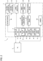
- FIG. 2 shows a control configuration of the laser processing apparatus 1.
- a part of a basic configuration is omitted in the drawing, and dimensional ratios or the like of the drawn parts are not invariably accurate.
- an up-down direction is as shown in the figure.
- the laser processing apparatus 1 includes a PC 2 and a laser processing unit 3. Since the PC 2 is a general PC, the description of a configuration thereof is omitted.
- the laser processing unit 3 is configured to perform marking (printing) processing by two-dimensionally scanning a surface 8 to be processed of an object 7 to be processed with a processing laser beam P.
- the laser processing unit 3 includes a controller 6.
- the controller 6 is implemented by a computer, and is connected to the PC 2 via, for example, USB, Ethernet, wireless LAN, or RS-232C so as to be capable of two-way communication.
- the controller 6 is configured to drive and control the laser processing unit 3 based on printing information, parameters, various types of instruction information, and the like transmitted from the PC 2.
- the laser processing unit 3 includes a laser oscillation unit 12, a guide light portion 15, a dichroic mirror 101, an optical system 70, a camera 103, a galvano scanner 18, an f ⁇ lens 19, and the like, and is covered with a substantially rectangular parallelepiped housing cover that is not shown.
- the laser oscillation unit 12 includes a laser oscillator 21 or the like.
- the laser oscillator 21 includes a CO2 laser, a YAG laser, or the like, and emits the processing laser beam P.
- a diameter of the processing laser beam P is adjusted (for example, enlarged) by a beam expander that is not shown.
- the guide light portion 15 includes a visible semiconductor laser 28 or the like.
- the visible semiconductor laser 28 is configured to emit guide light Q that is visible coherent light, for example, a red laser beam.
- the guide light Q is collimated by a lens group that is not shown, and further draws, by performing two-dimensional scanning, for example, an image of a print pattern to be subjected to marking (printing) processing with the processing laser beam P (hereinafter, referred to as an "object"), a rectangular image surrounding the object, or the like on the surface 8 of the object 7 as trajectories (residual time due to reflection). That is, the guide light Q has no marking (printing) processing capability.
- a wavelength of the guide light Q is different from a wavelength of the processing laser beam P.
- the wavelength of the processing laser beam P is 1064 nm
- the wavelength of the guide light Q is 650 nm.
- the guide light Q is incident at an incident angle of 45 degrees at a substantially central position of the dichroic mirror 101 through which the processing laser beam P passes, and is reflected on an optical path of the processing laser beam P at a reflection angle of 45 degrees.
- a reflectance of the dichroic mirror 101 has wavelength dependence. Specifically, the dichroic mirror 101 is surface-treated with a multilayer film structure of a dielectric layer and a metal layer, has a high reflectance with respect to the wavelength of the guide light Q, and allows almost (99%) light having a wavelength other than the wavelength of the guide light Q to pass therethrough.
- An one-dot chain line in FIG. 1 indicates an optical axis 10 of the processing laser beam P and the guide light Q.
- a direction of the optical axis 10 indicates a path direction of the processing laser beam P and the guide light Q.
- the optical system 70 includes a first lens 72, a second lens 74, and a moving mechanism 76.
- the processing laser beam P and the guide light Q which pass through the dichroic mirror 101, are incident on and pass through the first lens 72.
- respective diameters of the processing laser beam P and the guide light Q are reduced by the first lens 72.
- the processing laser beam P and the guide light Q which pass through the first lens 72, are incident on and pass through the second lens 74.
- the processing laser beam P and the guide light Q are collimated by the second lens 74.
- the moving mechanism 76 includes an optical system motor 80, a rack and pinion (not shown) configured to convert a rotational motion of the optical system motor 80 into a linear motion, and the like.
- the moving mechanism 76 is configured to move the second lens 74 in the path direction of the processing laser beam P and the guide light Q by rotation control of the optical system motor 80.
- the moving mechanism 76 may be configured to move the first lens 72 instead of the second lens 74, or may be configured to move both the first lens 72 and the second lens 74 such that a distance between the first lens 72 and the second lens 74 changes.
- the galvano scanner 18 is configured to perform two-dimensional scanning with the processing laser beam P and the guide light Q that pass through the optical system 70.
- a galvano X-axis motor 31 and a galvano Y-axis motor 32 are attached such that respective motor shafts are orthogonal to each other, and scanning mirrors 18X and 18Y, attached to ends of the respective motor shafts, face each other inside.
- the two-dimensional scanning is performed with the processing laser beam P and the guide light Q.
- Two-dimensional scanning directions are an X direction and a Y direction.
- a reference position which is an initial position (angle) of each of the scanning mirrors 18X and 18Y at which a scanning operation is started, is set in the galvano scanner 18, at the time of starting a laser processing operation or at the time of turning on a power supply of the laser processing apparatus 1.
- the reference position is indicated by a reference coordinate value in a coordinate signal, and in a case where the galvano scanner 18 takes the reference coordinate value, no excessive load is applied to each of the motors 31 and 32, and a stable scanning operation can be started.
- the reference coordinate value is often set to an origin (0, 0) in an XY coordinate system of a laser irradiation region, and the reference coordinate value is also set to the origin in the present embodiment.
- the f ⁇ lens 19 is configured to condense the processing laser beam P and the guide light Q with which the galvano scanner 18 two-dimensionally scans the surface 8 of the object 7. Therefore, the surface 8 of the object 7 is two-dimensionally scanned with the processing laser beam P and the guide light Q in the X direction and the Y direction by the rotation control of the motors 31 and 32.
- the processing laser beam P and the guide light Q have different wavelengths. Therefore, in a case where the distance between the first lens 72 and the second lens 74 in the optical system 70 is constant, positions at which the processing laser beam P and the guide light Q are condensed (hereinafter referred to as "focal positions F") are different in the up-down direction. Therefore, the focal positions F of the processing laser beam P and the guide light Q are aligned on the surface 8 of the object 7, by adjusting the distance between the first lens 72 and the second lens 74 in the optical system 70.
- the focal positions F of the processing laser beam P and the guide light Q are aligned on the surface 8 of the object 7, by adjusting the distance between the first lens 72 and the second lens 74 in the optical system 70.
- the camera 103 is provided near the f ⁇ lens 19 while facing the surface 8 of the object 7. Accordingly, the camera 103 may be configured to capture, for example, an image of the guide light Q emitted to the surface 8 of the object 7 and to display the image of the guide light Q on a liquid crystal display (LCD) 56 to be described later, such that a user may confirm whether the alignment between a processing image and the object 7 is appropriate.
- LCD liquid crystal display
- the laser processing unit 3 includes the controller 6, a galvano driver 36, a laser driver 37, a semiconductor laser driver 38, an optical system driver 78, and the camera 103.
- the controller 6 is configured to control the entire laser processing unit 3.
- the controller 6 is electrically connected to the galvano driver 36, the laser driver 37, the semiconductor laser driver 38, the optical system driver 78, and the like.
- the external PC 2 is connected to the controller 6 and the camera 103 so as to be capable of two-way communication.
- the controller 6 is configured to receive information (for example, the printing information, the parameters for the laser processing unit 3, and various types of instruction information from the user) transmitted from the PC 2.
- the camera 103 is configured to receive information (for example, imaging instruction information) transmitted from the PC 2, and configured to transmit a captured image to the PC 2.
- the controller 6 includes a CPU 41, a RAM 42, a ROM 43, a galvano controller 35, a laser controller 34, the laser driver 37, and the like.
- the CPU 41 is an arithmetic device and a control device for controlling the entire laser processing unit 3.
- the CPU 41, the RAM 42, the ROM 43, and the like are connected to one another via a bus (not shown) to exchange data with one another.
- the RAM 42 is configured to temporarily store various arithmetic results calculated by the CPU 41, vector data 44 to be described later with reference to FIG. 3 , and the like.
- the ROM 43 is configured to store various programs, for example, a program of format conversion software 6a, a program of vector data conversion software 6b to be described later with reference to FIG. 3 , and a program of a control process to be described later with reference to FIGS. 5 and 6 .
- the CPU 41 is configured to perform various calculations and controls based on the programs stored in the ROM 43.
- the optical system driver 78 is configured to drive and control the optical system motor 80 based on the information received from the controller 6 to move the second lens 74.
- FIG. 3 shows a generation sequence of various data.
- the PC 2 is configured to transmit the printing information to the controller 6, in accordance with an instruction from the user.
- the printing information is information indicating characters and figures to be printed.
- the CPU 41 of the controller 6 is configured to activate the format conversion software 6a stored in the ROM 43 as described above, and to convert the printing information into a language recognizable by the controller 6 based on the format conversion software 6a.
- the character information after format conversion is transferred to the vector data conversion software 6b.
- the vector data conversion software 6b is also stored in the ROM 43 as described above, and the CPU 41 is configured to convert the converted character information into vector data based on the vector data conversion software 6b.
- the vector data is data used in a case where the laser processing unit 3 performs a printing processing with the processing laser beam P.
- the converted vector data is supplied to an FPGA 6c.
- the FPGA is an abbreviation of "Field-Programmable Gate Array”.
- the FPGA 6c is configured to generate an intensity signal indicating an output intensity of the laser oscillator 21, based on the supplied vector data and supplies the intensity signal to the laser oscillator 21, is configured to generate a coordinate signal indicating scanning coordinates of the processing laser beam P, and is configured to supply the coordinate signal to the galvano driver 36.
- the intensity signal is a PWM signal
- the coordinate signal is an analog signal.
- the FPGA 6c serves as the galvano controller 35, the laser controller 34, and the laser driver 37.
- FIG. 4 shows flows of various signals in the laser processing unit 3.
- a power supply unit 90 is configured to supply, for example, a power supply voltage of 48V to the inside of the laser processing unit 3, specifically, to the laser oscillator 21 or a galvano DC-DC converter 91.
- the galvano DC-DC converter 91 is configured to convert the power supply voltage of 48V from the power supply unit 90 into, for example, a power supply voltage of 15V, and is configured to supply the converted power supply voltage of 15V to the galvano driver 36 and the galvano motors 31 and 32.
- a DC-DC converter or the like configured to receive power supply from the power supply unit 48 and is configured to convert a power supply voltage to a power supply voltage suitable for the semiconductor driver 38 or the optical system driver 78 is also separately provided, but illustration and detailed description thereof are omitted.
- An output voltage from the power supply unit 90 is input to a first voltage detection circuit 95 and a second voltage detection circuit 96.
- the first voltage detection circuit 95 is configured to output a notification signal to the controller 6 while the output voltage of the power supply unit 90 is smaller than a first threshold value, for example, 20V.
- the second voltage detection circuit 96 is configured to output a notification signal to the controller 6 while the output voltage of the power supply unit 90 is smaller than a second threshold value, for example, 16V.
- the controller 6 is configured to output, to the galvano DC-DC converter 91, an enable signal (hereinafter, referred to as an "EN signal") for operating the galvano DC-DC converter 91.
- the controller 6 is configured to output a coordinate signal and an excitation control signal to the galvano driver 36, and is configured to output an intensity signal to the laser driver 37.
- the galvano driver 36 includes a drive signal generation circuit 36a, an excitation control circuit 36b, and a transistor circuit 36c.
- the drive signal generation circuit 36a is configured to generate drive signals for driving the galvano X-axis motor 31 and the galvano Y-axis motor 32, based on the coordinate signal supplied from the controller 6.
- the excitation control circuit 36b is configured to perform excitation control based on the excitation control signal supplied from the controller 6.
- the drive signals generated by the drive signal generation circuit 36a are input to an input side of the transistor circuit 36c, and an excitation ON and OFF signal from the excitation control circuit 36b is input to a control input of the transistor circuit 36c.
- the transistor circuit 36c is configured to output the input drive signals as it is to the galvano X-axis motor 31 and the galvano Y-axis motor 32 in a case where an excitation ON signal is input, and is configured to stop the output of the input drive signals in a case where an excitation OFF signal is input.
- a circuit configuring the controller 6, the galvano DC-DC converter 91, or the galvano driver 36 is provided with a bypass capacitor having a corresponding static capacitance.
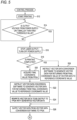
- FIGS. 5 and 6 show a procedure of the control process performed by the controller 6, particularly the CPU 41.
- the control process is started, for example, in a case where the laser processing apparatus 1 is instructed to start printing.
- a step is denoted as "S".
- step S12 the CPU 41 starts printing (step S12).
- step S14 the CPU 41 determines whether the first voltage detection circuit 95 detects that the output voltage from the power supply unit 90 is smaller than the first threshold value (step S14). The determination is made by determining whether the first voltage detection circuit 95 outputs the notification signal.
- step S14: NO the CPU 41 waits until the first voltage detection circuit 95 detects that the output voltage from the power supply unit 90 is smaller than the first threshold value, and when that the first voltage detection circuit 95 detects that the output voltage from the power supply unit 90 is smaller than the first threshold value (step S14: YES), the CPU 41 advances the process to step S16.
- step S 16 when the laser oscillator 21 is outputting, the CPU 41 stops laser output of the laser oscillator 21. Specifically, the CPU 41 transfers data for generating vector data in which the intensity signal becomes "0" from the vector data conversion software 6b to the vector data conversion software 6b. In a case where the laser output of the laser oscillator 21 is stopped or is in a stopped state, the power supply from the power supply unit 90 to the laser oscillator 21 is further stopped.
- the CPU 41 determines whether printing is completed (step S18). When the printing is not completed (step S18: NO), the CPU 41 acquires a final coordinate value from the FPGA 6c (step S20).
- the final coordinate value is a coordinate value of the coordinate signal output by the FPGA 6c in a case where the laser output is stopped in step S16.
- the CPU 41 transfers, to the vector data conversion software 6b, the acquired final coordinate value and the reference coordinate value to be returned, and instructs the vector data conversion software 6b to generate vector data for returning from the final coordinate value to the reference coordinate value (step S22).
- the CPU 41 then rewrites the vector data prepared to be output to the FPGA 6c with the vector data generated by the vector data conversion software 6b in response to the instruction in step S22 (step S24).
- the CPU 41 supplies the vector data from the vector data conversion software 6b to the FPGA 6c (step S26).
- the vector data for returning from the final coordinate value to the reference coordinate value is supplied to the FPGA 6c, and the galvano driver 36 generates drive signals for returning the galvano scanner 18 to its reference position, and supplies the drive signals to the galvano X-axis motor 31 and the galvano Y-axis motor 32.
- step S18 when the printing is completed (step S18: YES), the CPU 41 transfers the final coordinates of the vector data and the reference coordinate value to be returned to the vector data conversion software 6b, and instructs the vector data conversion software 6b to generate the vector data for returning from the final coordinates to the reference coordinate value (step S28).
- a difference between the processing of step S28 and the processing of step S22 is that in the processing of step S28, since the printing is completed, final coordinates can be known in the vector data conversion software 6b without querying the FPGA 6c, and the FPGA 6c is not queried for the final coordinate value, whereas in the processing of S22, since the printing is not completed, no final coordinate cannot be known in the vector data conversion software 6b, and thus the FPGA 6c is queried for a final coordinate value.
- step S28 the CPU 41 advances the processing to step S26. This is because there is no vector data prepared to be output to the FPGA 6c next, and thus the CPU 41 does not need to perform the processing of step S24. Similar to when the processing proceeds from step S24 to step S26, when the processing proceeds from step S28 to step S26, the vector data for returning from the final coordinates to the reference coordinate value is supplied to the FPGA 6c, and thus the galvano driver 36 generates the drive signals for returning the galvano scanner 18 to the reference position, and supplies the drive signals to the galvano X-axis motor 31 and the galvano Y-axis motor 32.
- the CPU 41 determines whether the second voltage detection circuit 96 detects that the output voltage from the power supply unit 90 is smaller than the second threshold value (step S30 in FIG. 6 ). The determination is made by determining whether the second voltage detection circuit 96 outputs the notification signal. When the second voltage detection circuit 96 does not detect that the output voltage from the power supply unit 90 is smaller than the second threshold value (step S30: NO), the CPU 41 determines whether the output voltage from the power supply unit 90 returns to a voltage of the first threshold value (step S32). The determination is made by determining whether the first voltage detection circuit 95 stops outputting the notification signal.
- step S32: NO When the output voltage does not return to the voltage of the first threshold value (step S32: NO), the CPU 41 instructs the PC 2 to display, on a display (not shown) of the PC 2, a message indicating that the voltage is dropping (step S34), and then ends the control process. On the other hand, when the output voltage returns to the voltage of the first threshold value (step S32: YES), the CPU 41 ends the control process.
- step S30 the CPU 41 turns off a power supply of the galvano driver 36, turns off the excitation of the galvano X-axis motor 31 and the galvano Y-axis motor 32 (step S36), and then ends the control process.
- step S36 turning off the power supply of the galvano driver 36 specifically means that the controller 6 switches the EN signal output to the galvano DC-DC converter 91 to a disable signal.
- turning off the excitation of the galvano X-axis motor 31 and the galvano Y-axis motor 32 specifically means switching the excitation control signal, which is output from the controller 6 to the galvano driver 36, to a signal that causes the galvano driver 36 to output excitation off.
- the laser processing apparatus 1 of the present embodiment is configured to irradiate a workpiece with a laser beam to process the workpiece, and includes the laser oscillator 21 configured to generate the laser beam, the galvano scanner 18 configured to perform scanning with the laser beam from the laser oscillator 21, the power supply unit 90 configured to supply power to parts of the laser processing unit 3, such as the laser oscillator 21 and the galvano DC-DC converter 91, the first voltage detection circuit 95 configured to detect whether an output voltage from the power supply unit 90 is smaller than a predetermined threshold value, the controller 6 configured to receive input of processing data indicating a processing content of the workpiece, and the controller 6 configured to control the laser oscillator 21 and the galvano scanner 18 based on the processing data.
- the laser oscillator 21 configured to generate the laser beam
- the galvano scanner 18 configured to perform scanning with the laser beam from the laser oscillator 21
- the power supply unit 90 configured to supply power to parts of the laser processing unit 3, such as the laser oscillator 21 and the galvano DC-DC
- the controller 6 includes the vector data conversion software 6b configured to generate vector data used for a processing operation with the laser beam based on the processing data received by the controller 6, and the FPGA 6c configured to receive the vector data generated and transmitted by the vector data conversion software 6b and to output, to the galvano scanner 18, an operation command for performing a scanning operation based on the received vector data.
- the controller 6 is configured to execute: an operation position acquisition process of acquiring the final coordinate value of the galvano scanner 18 based on the vector data transmitted by the vector data conversion software 6b to the FPGA 6c (step S20); a feedback vector data generation process of calculating feedback vector data for returning the galvano scanner 18 to the reference coordinate value based on the final coordinate value of the galvano scanner 18 acquired in the operation position acquisition process and causing the vector data conversion software 6b to generate the calculated feedback vector data (step S22); and a feedback command output process of receiving the feedback vector data generated by the vector data conversion software 6b in the feedback vector data generation process and outputting a command for returning the galvano scanner 18 to the reference coordinate value based on the received feedback vector data (step S26).
- the final coordinate value of the galvano scanner 18 is acquired based on the vector data transmitted from the vector data conversion software 6b to the FPGA 6c, the feedback vector data for returning the galvano scanner 18 to the reference coordinate value is calculated based on the acquired final coordinate value of the galvano scanner 18, the calculated feedback vector data is generated by the vector data conversion software 6b, the feedback vector data generated by the vector data conversion software 6b is received, and the command for returning the galvano scanner 18 to the reference coordinate value is output based on the received feedback vector data, and thus occurrence of an overcurrent from the power supply can be reduced when the galvano scanner 18 is restarted after being stopped due to a decrease in supply power.
- the galvano scanner 18 is an example of a "scanning unit".
- the power supply unit 90 is an example of a "power supply”.
- the first voltage detection circuit 95 is an example of a "voltage detection unit”.
- the controller 6 is an example of an "input unit” and a “control unit”.
- the vector data conversion software 6b is an example of a "data generation unit”.
- the FPGA 6c is an example of a "driver".
- the final coordinate value is an example of a "current operation position”.
- the reference coordinate value is an example of a "predetermined reference position".
- the controller 6 executes a stop process of stopping the laser output of the laser oscillator 21. Accordingly, when the laser oscillator 21 is restarted after being stopped due to the decrease in supply power, there is no possibility of emitting the laser beam against an intention of the user, thereby improving safety.
- the controller 6 executes a power supply-off process of turning off the power supply unit 90 after disconnecting electrical connection to the galvano scanner 18. Accordingly, a time margin is secured from when the command for returning the galvano scanner 18 to the reference coordinate value is output until the power supply is turned off, and thus the galvano scanner 18 can be reliably returned to the reference coordinate value.
- the second voltage detection circuit 96 is an example of a "voltage detection unit".
- the feedback vector data is calculated.
- the feedback date is to be used to cause the galvano scanner 18 to return to the predetermined reference position at a higher operation speed as a distance between the current operation position of the galvano scanner 18 acquired in the operation position acquisition process and the predetermined reference position is longer.
- the calculated feedback vector data is generated by the vector data conversion software 6b. This enables the galvano scanner 18 to return to the reference coordinate value more reliably.
Landscapes
- Physics & Mathematics (AREA)
- Optics & Photonics (AREA)
- Engineering & Computer Science (AREA)
- Mechanical Engineering (AREA)
- Plasma & Fusion (AREA)
- Laser Beam Processing (AREA)
Abstract
Description
- The present disclosure relates to a technique for laser processing an object.
- Patent Literature 1 discloses a laser processing apparatus configured to enable gap control for controlling a distance between a processing nozzle configured to irradiate a workpiece with a laser beam and a processing portion of the workpiece to a predetermined value until an abnormality in supply power is detected, and configured to disable the gap control in a case where the abnormality in supply power is detected.
- Patent Literature 1:
JP2015-182105A - However, the laser processing apparatus described in Patent Literature 1 does not refer to a scanning unit configured to perform scanning with a laser beam in a case where the abnormality in supply power is detected, and cannot cope with a problem that may occur in a case where the scanning unit is stopped in a state in which a scanning position is unknown due to, for example, a rapid decrease in supply power. Specifically, in this case, after the scanning unit is stopped in the state in which the scanning position is unknown, in a case where the supply power returns to a normal state and the scanning unit is restarted, an overcurrent may occur from a power supply configured to supply power to the scanning unit depending on the scanning position at which the scanning unit is stopped before the restart.
- An object of the present disclosure is to provide a technique capable of reducing occurrence of an overcurrent from a power supply in a case where a scanning unit is restarted after being stopped due to a decrease in supply power.
- In order to achieve the above-described object, a laser processing apparatus according to the present disclosure is a laser processing apparatus includes a scanning unit configured to perform scanning with the laser beam, a voltage detector configured to detect whether an output voltage from the power supply is smaller than a predetermined threshold value, and a controller configured to control the laser oscillator and the scanning unit, based on the processing data. The controller includes a data generator configured to generate vector data used for a processing operation with the laser beam, based on the processing data, and a driver configured to receive the vector data generated and transmitted by the data generator and configured to output, to the scanning unit, an operation command for performing a scanning operation based on the received vector data. In a case where the voltage detector detects that the output voltage is smaller than a first threshold value, during the processing operation with the laser beam, the controller is configured to perform an operation position acquisition process of acquiring a current operation position of the scanning unit, based on the vector data transmitted from the data generator to the driver, a feedback vector data generation process of calculating feedback vector data for returning the scanning unit to a predetermined reference position, based on the current operation position of the scanning unit acquired in the operation position acquisition process, and of causing the data generator to generate the calculated feedback vector data, and a feedback command output process of receiving the feedback vector data generated by the data generator in the feedback vector data generation process, and of outputting a command for returning the scanning unit to the predetermined reference position, based on the received feedback vector data.
- According to the present disclosure, it is possible to reduce occurrence of an overcurrent from the power supply in a case where the scanning unit is restarted after being stopped due to a decrease in supply power.
-
-
FIG. 1 is a diagram showing a schematic configuration of a laser processing apparatus according to an embodiment of the present disclosure. -
FIG. 2 is a block diagram showing a control configuration of the laser processing apparatus inFIG. 1 . -
FIG. 3 is a diagram showing a generation sequence of various data. -
FIG. 4 is a diagram showing flows of various signals in a laser processing unit inFIG. 1 . -
FIG. 5 is a flowchart showing a procedure of a control process to be executed by a controller, particularly a CPU. -
FIG. 6 is a flowchart showing a continuation of the control process inFIG. 5 . - Hereinafter, an embodiment of the present disclosure will be described in detail with reference to the drawings.
FIG. 1 shows a schematic configuration of a laser processing apparatus 1 according to an embodiment of the present disclosure, andFIG. 2 shows a control configuration of the laser processing apparatus 1. InFIGS. 1 and2 , a part of a basic configuration is omitted in the drawing, and dimensional ratios or the like of the drawn parts are not invariably accurate. In addition, inFIG. 1 , an up-down direction is as shown in the figure. - As shown in
FIG. 2 , the laser processing apparatus 1 includes aPC 2 and alaser processing unit 3. Since the PC 2 is a general PC, the description of a configuration thereof is omitted. - The
laser processing unit 3 is configured to perform marking (printing) processing by two-dimensionally scanning a surface 8 to be processed of an object 7 to be processed with a processing laser beam P. Thelaser processing unit 3 includes acontroller 6. - The
controller 6 is implemented by a computer, and is connected to the PC 2 via, for example, USB, Ethernet, wireless LAN, or RS-232C so as to be capable of two-way communication. Thecontroller 6 is configured to drive and control thelaser processing unit 3 based on printing information, parameters, various types of instruction information, and the like transmitted from the PC 2. - As shown in
FIG. 1 , thelaser processing unit 3 includes alaser oscillation unit 12, aguide light portion 15, adichroic mirror 101, anoptical system 70, acamera 103, agalvano scanner 18, anfθ lens 19, and the like, and is covered with a substantially rectangular parallelepiped housing cover that is not shown. - The
laser oscillation unit 12 includes alaser oscillator 21 or the like. Thelaser oscillator 21 includes a CO2 laser, a YAG laser, or the like, and emits the processing laser beam P. A diameter of the processing laser beam P is adjusted (for example, enlarged) by a beam expander that is not shown. - The
guide light portion 15 includes avisible semiconductor laser 28 or the like. Thevisible semiconductor laser 28 is configured to emit guide light Q that is visible coherent light, for example, a red laser beam. The guide light Q is collimated by a lens group that is not shown, and further draws, by performing two-dimensional scanning, for example, an image of a print pattern to be subjected to marking (printing) processing with the processing laser beam P (hereinafter, referred to as an "object"), a rectangular image surrounding the object, or the like on the surface 8 of the object 7 as trajectories (residual time due to reflection). That is, the guide light Q has no marking (printing) processing capability. - A wavelength of the guide light Q is different from a wavelength of the processing laser beam P. In the present embodiment, for example, the wavelength of the processing laser beam P is 1064 nm, and the wavelength of the guide light Q is 650 nm.
- Almost all of the incident processing laser beam P passes through the
dichroic mirror 101. In addition, in thedichroic mirror 101, the guide light Q is incident at an incident angle of 45 degrees at a substantially central position of thedichroic mirror 101 through which the processing laser beam P passes, and is reflected on an optical path of the processing laser beam P at a reflection angle of 45 degrees. A reflectance of thedichroic mirror 101 has wavelength dependence. Specifically, thedichroic mirror 101 is surface-treated with a multilayer film structure of a dielectric layer and a metal layer, has a high reflectance with respect to the wavelength of the guide light Q, and allows almost (99%) light having a wavelength other than the wavelength of the guide light Q to pass therethrough. - An one-dot chain line in
FIG. 1 indicates anoptical axis 10 of the processing laser beam P and the guide light Q. In addition, a direction of theoptical axis 10 indicates a path direction of the processing laser beam P and the guide light Q. - The
optical system 70 includes afirst lens 72, asecond lens 74, and amoving mechanism 76. In theoptical system 70, the processing laser beam P and the guide light Q, which pass through thedichroic mirror 101, are incident on and pass through thefirst lens 72. At this time, respective diameters of the processing laser beam P and the guide light Q are reduced by thefirst lens 72. In addition, the processing laser beam P and the guide light Q, which pass through thefirst lens 72, are incident on and pass through thesecond lens 74. At this time, the processing laser beam P and the guide light Q are collimated by thesecond lens 74. Themoving mechanism 76 includes anoptical system motor 80, a rack and pinion (not shown) configured to convert a rotational motion of theoptical system motor 80 into a linear motion, and the like. Themoving mechanism 76 is configured to move thesecond lens 74 in the path direction of the processing laser beam P and the guide light Q by rotation control of theoptical system motor 80. - The
moving mechanism 76 may be configured to move thefirst lens 72 instead of thesecond lens 74, or may be configured to move both thefirst lens 72 and thesecond lens 74 such that a distance between thefirst lens 72 and thesecond lens 74 changes. - The
galvano scanner 18 is configured to perform two-dimensional scanning with the processing laser beam P and the guide light Q that pass through theoptical system 70. In thegalvano scanner 18, agalvano X-axis motor 31 and a galvano Y-axis motor 32 are attached such that respective motor shafts are orthogonal to each other, and scanning mirrors 18X and 18Y, attached to ends of the respective motor shafts, face each other inside. By rotating the scanning mirrors 18X and 18Y by rotation control of themotors galvano scanner 18, at the time of starting a laser processing operation or at the time of turning on a power supply of the laser processing apparatus 1. The reference position is indicated by a reference coordinate value in a coordinate signal, and in a case where thegalvano scanner 18 takes the reference coordinate value, no excessive load is applied to each of themotors - The
fθ lens 19 is configured to condense the processing laser beam P and the guide light Q with which thegalvano scanner 18 two-dimensionally scans the surface 8 of the object 7. Therefore, the surface 8 of the object 7 is two-dimensionally scanned with the processing laser beam P and the guide light Q in the X direction and the Y direction by the rotation control of themotors - The processing laser beam P and the guide light Q have different wavelengths. Therefore, in a case where the distance between the
first lens 72 and thesecond lens 74 in theoptical system 70 is constant, positions at which the processing laser beam P and the guide light Q are condensed (hereinafter referred to as "focal positions F") are different in the up-down direction. Therefore, the focal positions F of the processing laser beam P and the guide light Q are aligned on the surface 8 of the object 7, by adjusting the distance between thefirst lens 72 and thesecond lens 74 in theoptical system 70. - In addition, even in a case where the positions of the surface 8 of the object 7 is changed in the up-down direction, similarly, the focal positions F of the processing laser beam P and the guide light Q are aligned on the surface 8 of the object 7, by adjusting the distance between the
first lens 72 and thesecond lens 74 in theoptical system 70. - The
camera 103 is provided near thefθ lens 19 while facing the surface 8 of the object 7. Accordingly, thecamera 103 may be configured to capture, for example, an image of the guide light Q emitted to the surface 8 of the object 7 and to display the image of the guide light Q on a liquid crystal display (LCD) 56 to be described later, such that a user may confirm whether the alignment between a processing image and the object 7 is appropriate. - Next, a control configuration of the
laser processing unit 3 included in the laser processing apparatus 1 will be described with reference toFIG. 2 . - As shown in
FIG. 2 , thelaser processing unit 3 includes thecontroller 6, agalvano driver 36, alaser driver 37, asemiconductor laser driver 38, anoptical system driver 78, and thecamera 103. Thecontroller 6 is configured to control the entirelaser processing unit 3. Thecontroller 6 is electrically connected to thegalvano driver 36, thelaser driver 37, thesemiconductor laser driver 38, theoptical system driver 78, and the like. In addition, theexternal PC 2 is connected to thecontroller 6 and thecamera 103 so as to be capable of two-way communication. Thecontroller 6 is configured to receive information (for example, the printing information, the parameters for thelaser processing unit 3, and various types of instruction information from the user) transmitted from thePC 2. Thecamera 103 is configured to receive information (for example, imaging instruction information) transmitted from thePC 2, and configured to transmit a captured image to thePC 2. - The
controller 6 includes aCPU 41, aRAM 42, aROM 43, agalvano controller 35, alaser controller 34, thelaser driver 37, and the like. TheCPU 41 is an arithmetic device and a control device for controlling the entirelaser processing unit 3. TheCPU 41, theRAM 42, theROM 43, and the like are connected to one another via a bus (not shown) to exchange data with one another. - The
RAM 42 is configured to temporarily store various arithmetic results calculated by theCPU 41,vector data 44 to be described later with reference toFIG. 3 , and the like. - The
ROM 43 is configured to store various programs, for example, a program offormat conversion software 6a, a program of vectordata conversion software 6b to be described later with reference toFIG. 3 , and a program of a control process to be described later with reference toFIGS. 5 and6 . - The
CPU 41 is configured to perform various calculations and controls based on the programs stored in theROM 43. - The
optical system driver 78 is configured to drive and control the optical system motor 80 based on the information received from thecontroller 6 to move thesecond lens 74. -
FIG. 3 shows a generation sequence of various data. ThePC 2 is configured to transmit the printing information to thecontroller 6, in accordance with an instruction from the user. The printing information is information indicating characters and figures to be printed. Upon receiving the printing information, theCPU 41 of thecontroller 6 is configured to activate theformat conversion software 6a stored in theROM 43 as described above, and to convert the printing information into a language recognizable by thecontroller 6 based on theformat conversion software 6a. The character information after format conversion is transferred to the vectordata conversion software 6b. The vectordata conversion software 6b is also stored in theROM 43 as described above, and theCPU 41 is configured to convert the converted character information into vector data based on the vectordata conversion software 6b. The vector data is data used in a case where thelaser processing unit 3 performs a printing processing with the processing laser beam P. The converted vector data is supplied to anFPGA 6c. The FPGA is an abbreviation of "Field-Programmable Gate Array". TheFPGA 6c is configured to generate an intensity signal indicating an output intensity of thelaser oscillator 21, based on the supplied vector data and supplies the intensity signal to thelaser oscillator 21, is configured to generate a coordinate signal indicating scanning coordinates of the processing laser beam P, and is configured to supply the coordinate signal to thegalvano driver 36. In the present embodiment, the intensity signal is a PWM signal, and the coordinate signal is an analog signal. As described above, theFPGA 6c serves as thegalvano controller 35, thelaser controller 34, and thelaser driver 37. -
FIG. 4 shows flows of various signals in thelaser processing unit 3. Apower supply unit 90 is configured to supply, for example, a power supply voltage of 48V to the inside of thelaser processing unit 3, specifically, to thelaser oscillator 21 or a galvano DC-DC converter 91. The galvano DC-DC converter 91 is configured to convert the power supply voltage of 48V from thepower supply unit 90 into, for example, a power supply voltage of 15V, and is configured to supply the converted power supply voltage of 15V to thegalvano driver 36 and thegalvano motors semiconductor driver 38 or theoptical system driver 78 is also separately provided, but illustration and detailed description thereof are omitted. - An output voltage from the
power supply unit 90 is input to a firstvoltage detection circuit 95 and a secondvoltage detection circuit 96. The firstvoltage detection circuit 95 is configured to output a notification signal to thecontroller 6 while the output voltage of thepower supply unit 90 is smaller than a first threshold value, for example, 20V. On the other hand, the secondvoltage detection circuit 96 is configured to output a notification signal to thecontroller 6 while the output voltage of thepower supply unit 90 is smaller than a second threshold value, for example, 16V. - The
controller 6 is configured to output, to the galvano DC-DC converter 91, an enable signal (hereinafter, referred to as an "EN signal") for operating the galvano DC-DC converter 91. In addition, thecontroller 6 is configured to output a coordinate signal and an excitation control signal to thegalvano driver 36, and is configured to output an intensity signal to thelaser driver 37. - The
galvano driver 36 includes a drivesignal generation circuit 36a, anexcitation control circuit 36b, and atransistor circuit 36c. The drivesignal generation circuit 36a is configured to generate drive signals for driving the galvanoX-axis motor 31 and the galvano Y-axis motor 32, based on the coordinate signal supplied from thecontroller 6. On the other hand, theexcitation control circuit 36b is configured to perform excitation control based on the excitation control signal supplied from thecontroller 6. The drive signals generated by the drivesignal generation circuit 36a are input to an input side of thetransistor circuit 36c, and an excitation ON and OFF signal from theexcitation control circuit 36b is input to a control input of thetransistor circuit 36c. Thetransistor circuit 36c is configured to output the input drive signals as it is to the galvanoX-axis motor 31 and the galvano Y-axis motor 32 in a case where an excitation ON signal is input, and is configured to stop the output of the input drive signals in a case where an excitation OFF signal is input. Although not shown, a circuit configuring thecontroller 6, the galvano DC-DC converter 91, or thegalvano driver 36 is provided with a bypass capacitor having a corresponding static capacitance. Therefore, even in a case where the power supply to the circuit is interrupted for some reason (for example, instantaneous power failure), a voltage in the circuit does not immediately become zero, and the bypass capacitor serves as a backup power supply, and the voltage can be gradually reduced along with the power consumption while maintaining the voltage for a certain period of time. - The control process to be executed by the laser processing apparatus 1 as described above will be described in detail with reference to
FIGS. 5 and6 .FIGS. 5 and6 show a procedure of the control process performed by thecontroller 6, particularly theCPU 41. The control process is started, for example, in a case where the laser processing apparatus 1 is instructed to start printing. Hereinafter, in the description of the procedure of the control process, a step is denoted as "S". - In
FIG. 5 , first, theCPU 41 starts printing (step S12). Next, theCPU 41 determines whether the firstvoltage detection circuit 95 detects that the output voltage from thepower supply unit 90 is smaller than the first threshold value (step S14). The determination is made by determining whether the firstvoltage detection circuit 95 outputs the notification signal. When the firstvoltage detection circuit 95 does not detect that the output voltage from thepower supply unit 90 is smaller than the first threshold value (step S14: NO), theCPU 41 waits until the firstvoltage detection circuit 95 detects that the output voltage from thepower supply unit 90 is smaller than the first threshold value, and when that the firstvoltage detection circuit 95 detects that the output voltage from thepower supply unit 90 is smaller than the first threshold value (step S14: YES), theCPU 41 advances the process to step S16. - In
step S 16, when thelaser oscillator 21 is outputting, theCPU 41 stops laser output of thelaser oscillator 21. Specifically, theCPU 41 transfers data for generating vector data in which the intensity signal becomes "0" from the vectordata conversion software 6b to the vectordata conversion software 6b. In a case where the laser output of thelaser oscillator 21 is stopped or is in a stopped state, the power supply from thepower supply unit 90 to thelaser oscillator 21 is further stopped. - Next, the
CPU 41 determines whether printing is completed (step S18). When the printing is not completed (step S18: NO), theCPU 41 acquires a final coordinate value from theFPGA 6c (step S20). The final coordinate value is a coordinate value of the coordinate signal output by theFPGA 6c in a case where the laser output is stopped in step S16. - Next, the
CPU 41 transfers, to the vectordata conversion software 6b, the acquired final coordinate value and the reference coordinate value to be returned, and instructs the vectordata conversion software 6b to generate vector data for returning from the final coordinate value to the reference coordinate value (step S22). At this time, it is preferred to instruct the vectordata conversion software 6b to generate vector data for returning at the highest speed. In addition, it is preferred to instruct the vectordata conversion software 6b to generate vector data for returning to the reference coordinate value at a higher speed as a distance between the final coordinate value and the reference coordinate value is longer. This is intended to operate the galvanoX-axis motor 31 and the galvano Y-axis motor 32 while voltages for driving the galvanoX-axis motor 31 and the galvano Y-axis motor 32 can be maintained by the bypass capacitor provided in the circuit included in the galvano DC-DC converter 91 or thegalvano driver 36. - Next, the
CPU 41 then rewrites the vector data prepared to be output to theFPGA 6c with the vector data generated by the vectordata conversion software 6b in response to the instruction in step S22 (step S24). - Next, the
CPU 41 supplies the vector data from the vectordata conversion software 6b to theFPGA 6c (step S26). When the process proceeds from step S24 to step S26, the vector data for returning from the final coordinate value to the reference coordinate value is supplied to theFPGA 6c, and thegalvano driver 36 generates drive signals for returning thegalvano scanner 18 to its reference position, and supplies the drive signals to the galvanoX-axis motor 31 and the galvano Y-axis motor 32. - On the other hand, when the printing is completed (step S18: YES), the
CPU 41 transfers the final coordinates of the vector data and the reference coordinate value to be returned to the vectordata conversion software 6b, and instructs the vectordata conversion software 6b to generate the vector data for returning from the final coordinates to the reference coordinate value (step S28). A difference between the processing of step S28 and the processing of step S22 is that in the processing of step S28, since the printing is completed, final coordinates can be known in the vectordata conversion software 6b without querying theFPGA 6c, and theFPGA 6c is not queried for the final coordinate value, whereas in the processing of S22, since the printing is not completed, no final coordinate cannot be known in the vectordata conversion software 6b, and thus theFPGA 6c is queried for a final coordinate value. - After the processing of step S28, the
CPU 41 advances the processing to step S26. This is because there is no vector data prepared to be output to theFPGA 6c next, and thus theCPU 41 does not need to perform the processing of step S24. Similar to when the processing proceeds from step S24 to step S26, when the processing proceeds from step S28 to step S26, the vector data for returning from the final coordinates to the reference coordinate value is supplied to theFPGA 6c, and thus thegalvano driver 36 generates the drive signals for returning thegalvano scanner 18 to the reference position, and supplies the drive signals to the galvanoX-axis motor 31 and the galvano Y-axis motor 32. - Next, the
CPU 41 determines whether the secondvoltage detection circuit 96 detects that the output voltage from thepower supply unit 90 is smaller than the second threshold value (step S30 inFIG. 6 ). The determination is made by determining whether the secondvoltage detection circuit 96 outputs the notification signal. When the secondvoltage detection circuit 96 does not detect that the output voltage from thepower supply unit 90 is smaller than the second threshold value (step S30: NO), theCPU 41 determines whether the output voltage from thepower supply unit 90 returns to a voltage of the first threshold value (step S32). The determination is made by determining whether the firstvoltage detection circuit 95 stops outputting the notification signal. When the output voltage does not return to the voltage of the first threshold value (step S32: NO), theCPU 41 instructs thePC 2 to display, on a display (not shown) of thePC 2, a message indicating that the voltage is dropping (step S34), and then ends the control process. On the other hand, when the output voltage returns to the voltage of the first threshold value (step S32: YES), theCPU 41 ends the control process. - On the other hand, when the second
voltage detection circuit 96 detects that the output voltage from thepower supply unit 90 is smaller than the second threshold value (step S30: YES), theCPU 41 turns off a power supply of thegalvano driver 36, turns off the excitation of the galvanoX-axis motor 31 and the galvano Y-axis motor 32 (step S36), and then ends the control process. In the processing of step S36, turning off the power supply of thegalvano driver 36 specifically means that thecontroller 6 switches the EN signal output to the galvano DC-DC converter 91 to a disable signal. In addition, turning off the excitation of the galvanoX-axis motor 31 and the galvano Y-axis motor 32 specifically means switching the excitation control signal, which is output from thecontroller 6 to thegalvano driver 36, to a signal that causes thegalvano driver 36 to output excitation off. - As described above, the laser processing apparatus 1 of the present embodiment is configured to irradiate a workpiece with a laser beam to process the workpiece, and includes the
laser oscillator 21 configured to generate the laser beam, thegalvano scanner 18 configured to perform scanning with the laser beam from thelaser oscillator 21, thepower supply unit 90 configured to supply power to parts of thelaser processing unit 3, such as thelaser oscillator 21 and the galvano DC-DC converter 91, the firstvoltage detection circuit 95 configured to detect whether an output voltage from thepower supply unit 90 is smaller than a predetermined threshold value, thecontroller 6 configured to receive input of processing data indicating a processing content of the workpiece, and thecontroller 6 configured to control thelaser oscillator 21 and thegalvano scanner 18 based on the processing data. - The
controller 6 includes the vectordata conversion software 6b configured to generate vector data used for a processing operation with the laser beam based on the processing data received by thecontroller 6, and theFPGA 6c configured to receive the vector data generated and transmitted by the vectordata conversion software 6b and to output, to thegalvano scanner 18, an operation command for performing a scanning operation based on the received vector data. - In a case where the first
voltage detection circuit 95 detects that the output voltage from thepower supply unit 90 is smaller than the first threshold value during the processing operation with the laser beam, thecontroller 6 is configured to execute: an operation position acquisition process of acquiring the final coordinate value of thegalvano scanner 18 based on the vector data transmitted by the vectordata conversion software 6b to theFPGA 6c (step S20); a feedback vector data generation process of calculating feedback vector data for returning thegalvano scanner 18 to the reference coordinate value based on the final coordinate value of thegalvano scanner 18 acquired in the operation position acquisition process and causing the vectordata conversion software 6b to generate the calculated feedback vector data (step S22); and a feedback command output process of receiving the feedback vector data generated by the vectordata conversion software 6b in the feedback vector data generation process and outputting a command for returning thegalvano scanner 18 to the reference coordinate value based on the received feedback vector data (step S26). - As described above, in the laser processing apparatus 1 of the present embodiment, when it is detected that the output voltage from the
power supply unit 90 is smaller than the first threshold value during the processing operation with the laser beam, the final coordinate value of thegalvano scanner 18 is acquired based on the vector data transmitted from the vectordata conversion software 6b to theFPGA 6c, the feedback vector data for returning thegalvano scanner 18 to the reference coordinate value is calculated based on the acquired final coordinate value of thegalvano scanner 18, the calculated feedback vector data is generated by the vectordata conversion software 6b, the feedback vector data generated by the vectordata conversion software 6b is received, and the command for returning thegalvano scanner 18 to the reference coordinate value is output based on the received feedback vector data, and thus occurrence of an overcurrent from the power supply can be reduced when thegalvano scanner 18 is restarted after being stopped due to a decrease in supply power. - In the present embodiment, the
galvano scanner 18 is an example of a "scanning unit". Thepower supply unit 90 is an example of a "power supply". The firstvoltage detection circuit 95 is an example of a "voltage detection unit". Thecontroller 6 is an example of an "input unit" and a "control unit". The vectordata conversion software 6b is an example of a "data generation unit". TheFPGA 6c is an example of a "driver". The final coordinate value is an example of a "current operation position". The reference coordinate value is an example of a "predetermined reference position". - In a case where the first
voltage detection circuit 95 detects that the output voltage from thepower supply unit 90 is smaller than the first threshold value during the processing operation with the laser beam, thecontroller 6 executes a stop process of stopping the laser output of thelaser oscillator 21. Accordingly, when thelaser oscillator 21 is restarted after being stopped due to the decrease in supply power, there is no possibility of emitting the laser beam against an intention of the user, thereby improving safety. - In addition, in a case where the second
voltage detection circuit 96 detects that the output voltage from thepower supply unit 90 is smaller than the second threshold value, which is smaller than the first threshold value during the processing operation with the laser beam, thecontroller 6 executes a power supply-off process of turning off thepower supply unit 90 after disconnecting electrical connection to thegalvano scanner 18. Accordingly, a time margin is secured from when the command for returning thegalvano scanner 18 to the reference coordinate value is output until the power supply is turned off, and thus thegalvano scanner 18 can be reliably returned to the reference coordinate value. The secondvoltage detection circuit 96 is an example of a "voltage detection unit". - In addition, in the feedback vector data generation process, the feedback vector data is calculated. The feedback date is to be used to cause the
galvano scanner 18 to return to the predetermined reference position at a higher operation speed as a distance between the current operation position of thegalvano scanner 18 acquired in the operation position acquisition process and the predetermined reference position is longer. The calculated feedback vector data is generated by the vectordata conversion software 6b. This enables thegalvano scanner 18 to return to the reference coordinate value more reliably. - The present disclosure is not limited to the above-described embodiment, and various modifications can be made without departing from the gist of the present disclosure.
- (1) In the above-described embodiment, the first threshold value and the second threshold value of the power supply voltage are detected by separate voltage detection circuits, and the present disclosure is not limited thereto, and the first threshold value and the second threshold value may be detected by one voltage detection circuit. The first threshold value and the second threshold value are fixed values, but may be changed by setting.
- (2) In the above-described embodiment, the laser output is stopped and the power supply to the
laser oscillator 21 is turned off at a timing when the firstvoltage detection circuit 95 detects that the output voltage from thepower supply unit 90 is smaller than the first threshold value (step S16), and the present disclosure is not limited thereto. The laser output may be stopped and the power supply to thelaser oscillator 21 may be turned off at a timing when a third voltage detection circuit, which is newly provided, detects that the output voltage is smaller than a third threshold value different from the first threshold value. Alternatively, the operation may be controlled based on a determination criterion other than the output voltage from thepower supply unit 90. - 1: laser processing apparatus, 2: PC, 6: controller, 6a: format conversion software, 6b: vector data conversion software, 6c: FPGA, 18: galvano scanner, 21: laser oscillator, 31: galvano X-axis motor, 32: galvano Y-axis motor, 36: galvano driver, 36a: drive signal generation circuit, 36b: excitation control circuit, 37: laser driver, 41: CPU, 90: power supply unit, 91: galvano DC-DC converter, 95: first voltage detection circuit, 96: second voltage detection circuit
Claims (6)
- A laser processing apparatus for irradiating a workpiece with a laser beam to process the workpiece, the laser processing apparatus comprising:a laser oscillator configured to generate the laser beam;a scanning unit configured to perform scanning with the laser beam from the laser oscillator;a power supply configured to supply power to the laser oscillator and the scanning unit;a voltage detection unit configured to detect whether an output voltage from the power supply is smaller than a predetermined threshold value;an input unit configured to receive input of processing data indicating a processing content of the workpiece; anda control unit configured to control the laser oscillator and the scanning unit, based on the processing data,wherein the control unit includes:a data generation unit configured to generate vector data to be used for a processing operation with the laser beam, based on the processing data received from the input unit; anda driver configured to receive the vector data generated and transmitted by the data generation unit and configured to output, to the scanning unit, an operation command for performing a scanning operation based on the received vector data, andin a case where the voltage detection unit detects that the output voltage from the power supply is smaller than a first threshold value, during the processing operation with the laser beam, the control unit is configured to perform:an operation position acquisition process of acquiring a current operation position of the scanning unit, based on the vector data transmitted from the data generation unit to the driver,a feedback vector data generation process of calculating feedback vector data for returning the scanning unit to a predetermined reference position, based on the current operation position of the scanning unit acquired in the operation position acquisition process, and of causing the data generation unit to generate the calculated feedback vector data, anda feedback command output process of receiving the feedback vector data generated by the data generation unit in the feedback vector data generation process, and of outputting a command for returning the scanning unit to the predetermined reference position, based on the received feedback vector data.
- The laser processing apparatus according to claim 1,
wherein in a case where the voltage detection unit detects that the output voltage from the power supply is smaller than the first threshold value, during the processing operation with the laser beam, the control unit is configured to perform a stop process of stopping laser output of the laser oscillator. - The laser processing apparatus according to claim 1 or 2,
wherein in a case where, during the processing operation with the laser beam, the voltage detection unit detects that the output voltage from the power supply is smaller than a second threshold value smaller than the first threshold value, the control unit is configured to perform a power supply-off process of turning off the power supply after disconnecting electrical connection to the scanning unit. - The laser processing apparatus according to any one of claims 1 to 3,
wherein the scanning unit includes a galvano motor including a mirror. - The laser processing apparatus according to any one of claims 1 to 4,
wherein in the feedback vector data generation process, feedback vector data is to be calculated, and the calculated feedback vector data is to be generated from the data generation unit, the feedback vector fata being to be used to cause the scanner to return to the predetermined reference position at a higher operation speed as a distance between the current operation position of the scanner acquired in the operation position acquisition process and the predetermined reference position is longer. - A laser processing method using a laser processing apparatus, the laser processing apparatus for irradiating a workpiece with a laser beam to process a workpiece, the laser processing apparatus including: a laser oscillator configured to generate the laser beam; a scanning unit configured to perform scanning with the laser beam from the laser oscillator; a power supply configured to supply power to the laser oscillator and the scanning unit; a voltage detection unit configured to detect whether an output voltage from the power supply is smaller than a predetermined threshold value; and an input unit configured to receive input of processing data indicating a processing content of the workpiece with the laser beam, the method comprising:in a case where the voltage detection unit detects that the output voltage from the power supply is smaller than a first threshold value, during the processing operation with the laser beam, an operation position acquisition processing of receiving vector data generated and transmitted by a data generation unit, and of acquiring a current operation position of the scanning unit based on the vector data transmitted to a driver configured to output, to the scanning unit, an operation command for performing a scanning operation based on the received vector data, the data generator being configured to generate vector data used for processing operation with the laser beam based on the processing data received by the input unit;a feedback vector data generation processing of calculating feedback vector data for returning the scanning unit to a predetermined reference position based on the current operation position of the scanning unit acquired in the operation position acquisition processing, and of causing the data generation unit to generate the calculated feedback vector data, anda feedback command output processing of receiving the feedback vector data generated by the data generation unit in the feedback vector data generation processing, and of outputting a command for returning the scanning unit to the predetermined reference position, based on the received feedback vector data.
Applications Claiming Priority (2)
| Application Number | Priority Date | Filing Date | Title |
|---|---|---|---|
| JP2021162119A JP7714990B2 (en) | 2021-09-30 | 2021-09-30 | Laser processing device and laser processing method |
| PCT/JP2022/034170 WO2023053932A1 (en) | 2021-09-30 | 2022-09-13 | Laser machining apparatus and laser machining method |
Publications (2)
| Publication Number | Publication Date |
|---|---|
| EP4410468A1 true EP4410468A1 (en) | 2024-08-07 |
| EP4410468A4 EP4410468A4 (en) | 2025-10-22 |
Family
ID=85782434
Family Applications (1)
| Application Number | Title | Priority Date | Filing Date |
|---|---|---|---|
| EP22875804.1A Pending EP4410468A4 (en) | 2021-09-30 | 2022-09-13 | LASER PROCESSING DEVICE AND LASER PROCESSING METHOD |
Country Status (4)
| Country | Link |
|---|---|
| US (1) | US20240238894A1 (en) |
| EP (1) | EP4410468A4 (en) |
| JP (1) | JP7714990B2 (en) |
| WO (1) | WO2023053932A1 (en) |
Families Citing this family (1)
| Publication number | Priority date | Publication date | Assignee | Title |
|---|---|---|---|---|
| CN121355685B (en) * | 2025-12-19 | 2026-03-17 | 罗根激光科技(武汉)有限公司 | Intelligent control method and system for laser oscillator |
Family Cites Families (8)
| Publication number | Priority date | Publication date | Assignee | Title |
|---|---|---|---|---|
| JPS6388602A (en) * | 1986-10-01 | 1988-04-19 | Mitsubishi Electric Corp | Operating method for sequence control |
| DE4204721A1 (en) * | 1991-08-19 | 1994-03-17 | Roman Koller | Safety circuit e.g. for surgical laser - provides self-testing oscillation to verify function of safety circuit components and has learning function |
| JP4884897B2 (en) * | 2006-09-15 | 2012-02-29 | 株式会社キーエンス | Laser processing apparatus, control method thereof, and control program thereof |
| JP5340858B2 (en) * | 2009-08-31 | 2013-11-13 | パナソニック デバイスSunx株式会社 | Laser marking device and laser marking system |
| CN104105568B (en) * | 2013-02-14 | 2015-10-21 | 三菱电机株式会社 | Laser processing device, processing control device and pulse frequency control method |
| JP5887375B2 (en) | 2014-03-24 | 2016-03-16 | ファナック株式会社 | Laser processing equipment that retracts the processing nozzle when a power failure is detected |
| JP6137099B2 (en) * | 2014-09-29 | 2017-05-31 | ブラザー工業株式会社 | Laser processing apparatus and control program |
| JP6657640B2 (en) * | 2015-07-31 | 2020-03-04 | ブラザー工業株式会社 | Laser processing apparatus and control program for laser processing apparatus |
-
2021
- 2021-09-30 JP JP2021162119A patent/JP7714990B2/en active Active
-
2022
- 2022-09-13 WO PCT/JP2022/034170 patent/WO2023053932A1/en not_active Ceased
- 2022-09-13 EP EP22875804.1A patent/EP4410468A4/en active Pending
-
2024
- 2024-03-28 US US18/619,823 patent/US20240238894A1/en active Pending
Also Published As
| Publication number | Publication date |
|---|---|
| JP7714990B2 (en) | 2025-07-30 |
| WO2023053932A1 (en) | 2023-04-06 |
| US20240238894A1 (en) | 2024-07-18 |
| EP4410468A4 (en) | 2025-10-22 |
| JP2023051446A (en) | 2023-04-11 |
Similar Documents
| Publication | Publication Date | Title |
|---|---|---|
| US10493561B2 (en) | Laser machining device provided with laser emitter emitting laser beam and machining chamber | |
| JP6305270B2 (en) | Laser processing apparatus and working distance measurement method | |
| JP2002361463A (en) | Processing device and processing method | |
| US20240238894A1 (en) | Laser processing apparatus and laser processing method | |
| CN204771159U (en) | Laser machining device | |
| JP2018008307A (en) | Optical processing apparatus and optical workpiece production method | |
| US10661385B2 (en) | Laser machining apparatus projecting guide pattern onto workpiece by irradiating visible laser beam thereon | |
| KR20120007616A (en) | Galvanometer Scanner Controller for Laser Processing Equipment | |
| JPWO2014010046A1 (en) | Laser resonator control power supply, laser oscillator and laser oscillation system | |
| KR101425337B1 (en) | Laser processing apparatus, processing control apparatus, and pulse frequency control method | |
| JP4467333B2 (en) | Laser processing apparatus and processing method | |
| JP2017029992A (en) | Laser machining device | |
| JP7710154B2 (en) | Laser processing device and processing method | |
| JPH01162591A (en) | Laser beam scanner | |
| JP3185660B2 (en) | Marking method and device | |
| JP7310500B2 (en) | Laser processing equipment | |
| JP6137099B2 (en) | Laser processing apparatus and control program | |
| JP2004177502A (en) | Laser scanning device | |
| JP3850308B2 (en) | Method and apparatus for digital control of galvano scanner | |
| JP2024144986A (en) | Laser processing device and control method thereof | |
| JP2015196168A (en) | Laser machining apparatus, machining data creation apparatus, and program | |
| JP2024093611A (en) | Laser processing device and laser processing method | |
| JP2022101900A (en) | Laser processing equipment and laser processing method | |
| US20250042178A1 (en) | Laser printing apparatus | |
| JP2003329960A (en) | Method and device for controlling galvanoscanner |
Legal Events
| Date | Code | Title | Description |
|---|---|---|---|
| STAA | Information on the status of an ep patent application or granted ep patent |
Free format text: STATUS: THE INTERNATIONAL PUBLICATION HAS BEEN MADE |
|
| PUAI | Public reference made under article 153(3) epc to a published international application that has entered the european phase |
Free format text: ORIGINAL CODE: 0009012 |
|
| STAA | Information on the status of an ep patent application or granted ep patent |
Free format text: STATUS: REQUEST FOR EXAMINATION WAS MADE |
|
| 17P | Request for examination filed |
Effective date: 20240328 |
|
| AK | Designated contracting states |
Kind code of ref document: A1 Designated state(s): AL AT BE BG CH CY CZ DE DK EE ES FI FR GB GR HR HU IE IS IT LI LT LU LV MC MK MT NL NO PL PT RO RS SE SI SK SM TR |
|
| P01 | Opt-out of the competence of the unified patent court (upc) registered |
Free format text: CASE NUMBER: APP_45863/2024 Effective date: 20240807 |
|
| DAV | Request for validation of the european patent (deleted) | ||
| DAX | Request for extension of the european patent (deleted) | ||
| REG | Reference to a national code |
Ref country code: DE Ref legal event code: R079 Free format text: PREVIOUS MAIN CLASS: B23K0026000000 Ipc: B23K0026700000 |
|
| A4 | Supplementary search report drawn up and despatched |
Effective date: 20250924 |
|
| RIC1 | Information provided on ipc code assigned before grant |
Ipc: B23K 26/70 20140101AFI20250918BHEP Ipc: B23K 26/082 20140101ALI20250918BHEP Ipc: B23K 26/03 20060101ALI20250918BHEP |