EP4410176A1 - Optical transmitter module and endoscope - Google Patents
Optical transmitter module and endoscope Download PDFInfo
- Publication number
- EP4410176A1 EP4410176A1 EP22875825.6A EP22875825A EP4410176A1 EP 4410176 A1 EP4410176 A1 EP 4410176A1 EP 22875825 A EP22875825 A EP 22875825A EP 4410176 A1 EP4410176 A1 EP 4410176A1
- Authority
- EP
- European Patent Office
- Prior art keywords
- transmitter module
- optical transmitter
- cap member
- endoscope
- heat dissipation
- Prior art date
- Legal status (The legal status is an assumption and is not a legal conclusion. Google has not performed a legal analysis and makes no representation as to the accuracy of the status listed.)
- Pending
Links
Images



Classifications
-
- A—HUMAN NECESSITIES
- A61—MEDICAL OR VETERINARY SCIENCE; HYGIENE
- A61B—DIAGNOSIS; SURGERY; IDENTIFICATION
- A61B1/00—Instruments for performing medical examinations of the interior of cavities or tubes of the body by visual or photographical inspection, e.g. endoscopes; Illuminating arrangements therefor
-
- A—HUMAN NECESSITIES
- A61—MEDICAL OR VETERINARY SCIENCE; HYGIENE
- A61B—DIAGNOSIS; SURGERY; IDENTIFICATION
- A61B1/00—Instruments for performing medical examinations of the interior of cavities or tubes of the body by visual or photographical inspection, e.g. endoscopes; Illuminating arrangements therefor
- A61B1/00002—Operational features of endoscopes
- A61B1/00011—Operational features of endoscopes characterised by signal transmission
- A61B1/00013—Operational features of endoscopes characterised by signal transmission using optical means
-
- A—HUMAN NECESSITIES
- A61—MEDICAL OR VETERINARY SCIENCE; HYGIENE
- A61B—DIAGNOSIS; SURGERY; IDENTIFICATION
- A61B1/00—Instruments for performing medical examinations of the interior of cavities or tubes of the body by visual or photographical inspection, e.g. endoscopes; Illuminating arrangements therefor
- A61B1/00163—Optical arrangements
- A61B1/00165—Optical arrangements with light-conductive means, e.g. fibre optics
- A61B1/0017—Details of single optical fibres, e.g. material or cladding
-
- A—HUMAN NECESSITIES
- A61—MEDICAL OR VETERINARY SCIENCE; HYGIENE
- A61B—DIAGNOSIS; SURGERY; IDENTIFICATION
- A61B1/00—Instruments for performing medical examinations of the interior of cavities or tubes of the body by visual or photographical inspection, e.g. endoscopes; Illuminating arrangements therefor
- A61B1/04—Instruments for performing medical examinations of the interior of cavities or tubes of the body by visual or photographical inspection, e.g. endoscopes; Illuminating arrangements therefor combined with photographic or television appliances
-
- A—HUMAN NECESSITIES
- A61—MEDICAL OR VETERINARY SCIENCE; HYGIENE
- A61B—DIAGNOSIS; SURGERY; IDENTIFICATION
- A61B1/00—Instruments for performing medical examinations of the interior of cavities or tubes of the body by visual or photographical inspection, e.g. endoscopes; Illuminating arrangements therefor
- A61B1/04—Instruments for performing medical examinations of the interior of cavities or tubes of the body by visual or photographical inspection, e.g. endoscopes; Illuminating arrangements therefor combined with photographic or television appliances
- A61B1/05—Instruments for performing medical examinations of the interior of cavities or tubes of the body by visual or photographical inspection, e.g. endoscopes; Illuminating arrangements therefor combined with photographic or television appliances characterised by the image sensor, e.g. camera, being in the distal end portion
-
- A—HUMAN NECESSITIES
- A61—MEDICAL OR VETERINARY SCIENCE; HYGIENE
- A61B—DIAGNOSIS; SURGERY; IDENTIFICATION
- A61B1/00—Instruments for performing medical examinations of the interior of cavities or tubes of the body by visual or photographical inspection, e.g. endoscopes; Illuminating arrangements therefor
- A61B1/12—Instruments for performing medical examinations of the interior of cavities or tubes of the body by visual or photographical inspection, e.g. endoscopes; Illuminating arrangements therefor with cooling or rinsing arrangements
- A61B1/128—Instruments for performing medical examinations of the interior of cavities or tubes of the body by visual or photographical inspection, e.g. endoscopes; Illuminating arrangements therefor with cooling or rinsing arrangements provided with means for regulating temperature
-
- G—PHYSICS
- G02—OPTICS
- G02B—OPTICAL ELEMENTS, SYSTEMS OR APPARATUS
- G02B23/00—Telescopes, e.g. binoculars; Periscopes; Instruments for viewing the inside of hollow bodies; Viewfinders; Optical aiming or sighting devices
- G02B23/24—Instruments or systems for viewing the inside of hollow bodies, e.g. fibrescopes
- G02B23/2407—Optical details
- G02B23/2461—Illumination
- G02B23/2469—Illumination using optical fibres
-
- G—PHYSICS
- G02—OPTICS
- G02B—OPTICAL ELEMENTS, SYSTEMS OR APPARATUS
- G02B23/00—Telescopes, e.g. binoculars; Periscopes; Instruments for viewing the inside of hollow bodies; Viewfinders; Optical aiming or sighting devices
- G02B23/24—Instruments or systems for viewing the inside of hollow bodies, e.g. fibrescopes
- G02B23/26—Instruments or systems for viewing the inside of hollow bodies, e.g. fibrescopes using light guides
-
- H—ELECTRICITY
- H04—ELECTRIC COMMUNICATION TECHNIQUE
- H04N—PICTORIAL COMMUNICATION, e.g. TELEVISION
- H04N23/00—Cameras or camera modules comprising electronic image sensors; Control thereof
- H04N23/50—Constructional details
- H04N23/51—Housings
-
- H—ELECTRICITY
- H04—ELECTRIC COMMUNICATION TECHNIQUE
- H04N—PICTORIAL COMMUNICATION, e.g. TELEVISION
- H04N23/00—Cameras or camera modules comprising electronic image sensors; Control thereof
- H04N23/50—Constructional details
- H04N23/52—Elements optimising image sensor operation, e.g. for electromagnetic interference [EMI] protection or temperature control by heat transfer or cooling elements
-
- H—ELECTRICITY
- H04—ELECTRIC COMMUNICATION TECHNIQUE
- H04N—PICTORIAL COMMUNICATION, e.g. TELEVISION
- H04N23/00—Cameras or camera modules comprising electronic image sensors; Control thereof
- H04N23/50—Constructional details
- H04N23/54—Mounting of pick-up tubes, electronic image sensors, deviation or focusing coils
Definitions
- the present invention relates to an optical transmitter module and an endoscope.
- An endoscope in which an image sensor is built in a distal end of an insertion portion is known.
- an image sensor having a large number of pixels is used.
- an optical transmitter module is incorporated in the endoscope, and an optical fiber is used for signal transmission.
- Patent Literature 1 Examples of an optical transmitter module using an optical fiber are described in Patent Literature 1 and Patent Literature 2.
- Patent Literature 1 Although an FPC substrate is used in Patent Literature 1, if the FPC substrate is configured to be orthogonal with an adhesive as described in Patent Literature 1, the configuration may be unstable at the time of manufacturing. In addition, since an extra space is formed in the optical transmitter module, downsizing is difficult.
- the present invention has been made to solve such a problem, and aims to provide an optical transmitter module and an endoscope that can be more easily downsized with a more stable configuration.
- An optical transmitter module includes:
- An endoscope according to the present invention includes the optical transmitter module described above.
- optical transmitter module and the endoscope according to the present invention can be more easily downsized with a more stable configuration.
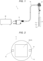
- Fig. 1 is a diagram illustrating a configuration example of an endoscope system 1 according to the present embodiment.
- the endoscope system 1 may be what is called an electronic endoscope.
- the endoscope system 1 is, for example, a dedicated system for medical use and includes an endoscope unit 10 and a processor 20.
- the endoscope unit 10 includes an endoscope 11 and an operation unit 12.
- the endoscope 11 includes, in order from the distal end, a hard portion 11a that is not deformed, a bend portion 11b that can actively bend in response to an operation, and a flexible portion 11c that can be passively deformed.
- a user of the endoscope system 1 operates the operation unit 12 to control a movement of the endoscope 11.
- the bend portion 11b is bent depending on an operation of the operation unit 12.
- the bend portion 11b can be realized by using a known mechanism incorporated in a typical electronic scope, and is configured to bend the bend portion 11b by, for example, pulling an operation wire in conjunction with rotational operation of a knob included in the operation unit 12.
- the endoscope 11 can insert a portion including the hard portion 11a into any body cavity in a living body, for example, into a bronchus, a biliary tract, a pancreas, a hepatic duct region, a urinary organ region, or the like.
- the processor 20 integrally includes: a signal processing device that processes an image signal from the endoscope unit 10; and a light source device that applies light via the endoscope unit 10 to a body cavity to which no natural light can reach.
- a signal processing device that processes an image signal from the endoscope unit 10
- a light source device that applies light via the endoscope unit 10 to a body cavity to which no natural light can reach.
- the signal processing device and the light source device may be configured separately.
- a proximal end of the endoscope unit 10 is provided with a connector unit 13, and the processor 20 is provided with a connector unit 21.
- the connector unit 13 and the connector unit 21 each have a coupling structure corresponding to each other. Coupling of these structures electrically and optically connects the endoscope unit 10 and the processor 20.
- the processor 20 functions as a controller that controls the entire endoscope system 1 and includes, for example, a computer provided with an arithmetic unit and a storage unit.
- Other functions and configurations of the endoscope unit 10 and the processor 20 can be appropriately designed by those skilled in the art based on known techniques.
- the processor 20 performs various calculations on the basis of specific information of the endoscope unit 10 and generates a control signal.
- the processor 20 uses the generated control signal to control operations and timings of various circuits in the processor 20, thereby causing the endoscope unit 10 to move appropriately.
- the endoscope unit 10 is connected to an appropriate processor other than the processor 20, the endoscope unit 10 may be provided independently.
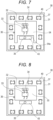
- Fig. 2 illustrates a configuration example of a distal end of the endoscope 11.
- Fig. 2 is a view (top view) of the distal end of the endoscope 11 as viewed from the distal end side in the axial direction.
- the "axial direction” and the "radial direction” mean the axial direction and the radial direction of the endoscope 11, respectively.
- the endoscope 11 includes an optical transmitter module 30.
- the configuration of the optical transmitter module 30 will be described later with reference to Figs. 3 and 4 , for example. In Fig. 2 , however, only an image sensor 31 of the optical transmitter module 30 appears.
- the optical transmitter module 30 is fixed in the endoscope 11 using a fixing member (for example, a rod 15).
- the structure of the fixing member is not limited to that shown in Fig. 2 , and those skilled in the art can appropriately design the fixing member.
- the endoscope 11 includes a light irradiation means 14.
- the light irradiation means 14 is provided at or near the distal end of the endoscope 11.
- the light irradiation means 14 is, for example, a ride guide, and more specifically, can be configured using an optical fiber.
- the endoscope 11 may further include other configurations included in a known endoscope.
- the endoscope 11 may include a forceps channel, an air pipe, a water pipe, a water jet pipe, and the like.
- the distal end of the endoscope 11 illustrated in Fig. 2 may be provided with an opening or the like corresponding thereto.
- Fig. 3 and Fig. 4 illustrate a configuration example of the optical transmitter module 30.
- Fig. 3 is a view (side view) of the optical transmitter module 30 as viewed from the radial direction
- Fig. 4 is a view (bottom view) of the optical transmitter module 30 as viewed from the rear end side in the axial direction.
- the optical transmitter module 30 includes the image sensor 31 described above, a laser element 32, a laser driver circuit 33, at least one optical fiber 34 (two in the present embodiment), a heat dissipation wiring 35, at least one electric signal wiring 36, and a layered substrate 37.
- the image sensor 31, the laser element 32, the laser driver circuit 33, the optical fiber 34, the heat dissipation wiring 35, and the electric signal wiring 36 are mounted on the layered substrate 37.
- the image sensor 31 is connected to the layered substrate 37 via a solder 42.
- the laser element 32 and the laser driver circuit 33 are mounted on the layered substrate 37 by die bonding and wire bonding, and in particular connected to the layered substrate 37 via wires 39.
- the laser element 32 and the laser driver circuit 33 constitute an electrical-optical converter that converts an electric signal output from the image sensor 31 into an optical signal.
- the optical fiber 34 is connected to the laser element 32 and conveys the laser output from the laser element 32.
- the heat dissipation wiring 35 is connected to a ground potential pad 43 and discharges heat of the optical transmitter module 30 (for example, heat generated by the image sensor 31) via the ground potential pad 43.
- a cable wiring pad 41 is provided on a side surface of the layered substrate 37 (that is, a surface parallel to the axis of the endoscope 11). Although three cable wiring pads 41 are illustrated in the example of Fig. 3 , the number of the cable wiring pads 41 may be one or more.
- the electric signal wiring 36 is connected to the layered substrate 37 via the cable wiring pad 41. For convenience of illustration, only one electric signal wiring 36 is illustrated in the examples of Figs. 3 and 4 , but the number of electric signal wiring 36 may be two or more, and for example, each of the cable wiring pads 41 may be connected to separated one electric signal wiring 36.
- a passive component 40 (for example, a capacitor, a resistor, and the like) may be connected to the layered substrate 37.
- the passive component 40 may be connected to the electric signal wiring 36 via the layered substrate 37.
- each component can be compactly arranged by a mounting style using the layered substrate 37, and the entire optical transmitter module 30 can be downsized.
- the optical transmitter module 30 includes a first cap member 50 made of glass. As illustrated in Figs. 3 and 4 , the first cap member 50 is disposed on a rear end side surface of the layered substrate 37 and covers the laser element 32, the laser driver circuit 33, the ground potential pad 43, and the like.
- Fig. 5 is a displacement cross-sectional view of the first cap member 50 taken along line V-V in Fig. 4 .
- the first cap member 50 includes a first through hole 51, a recess 52, and a second through hole 53.
- the first through hole 51 penetrates the first cap member 50 in the axial direction and is connected to the recess 52.
- the first through hole 51 accommodates at least a part of the optical fiber 34.
- a single first through hole 51 may accommodate the plurality of optical fibers 34, or a plurality of first through holes 51 may be provided and each of them may accommodate separated one optical fiber 34.
- a diameter of the optical fiber 34 may change along the axial direction.
- the optical fiber 34 has a small diameter portion where a core 34a is exposed, and a large diameter portion where the core 34a is covered with a clad portion (not illustrated in Fig. 5 ) and a covering portion 34c.
- the first through hole 51 may have a stepped hole shape as illustrated, that is, the diameter may change along the axial direction depending on a change in the diameter of the optical fiber 34.
- the recess 52 is formed so as to open toward a surface (distal end side) facing the layered substrate 37 in the first cap member 50, and accommodates the laser element 32 and the laser driver circuit 33. In the example of Fig. 5 , the recess 52 further accommodates the wires 39.
- the second through hole 53 penetrates the first cap member 50 in the axial direction and accommodates at least a part of the heat dissipation wiring 35.
- each accommodation target optical fiber 34, laser element 32, laser driver circuit 33, heat dissipation wiring 35, and the like
- first through hole 51 is configured to have a stepped hole shape as illustrated in Fig. 5
- positioning of the optical fiber 34 is further facilitated.
- the optical transmitter module 30 is sealed with a molding agent.
- Fig. 6 illustrates an example of sealing with a molding agent 61.
- a second cap member 60 having a tubular shape is attached to the optical transmitter module 30.
- the second cap member 60 has, for example, a bottomed tubular shape, but may have a tubular shape penetrating without a bottom.
- the second cap member 60 is made of, for example, resin but may be made of any material.
- the second cap member 60 is disposed so as to cover, from the distal end side of the optical transmitter module 30, the entire image sensor 31, the layered substrate 37, and the first cap member 50, and the inside of the second cap member 60 is filled with the molding agent 61.
- the whole including the second cap member 60 and the molding agent 61 can be disposed inside the hard portion 11a that is not deformed.
- the image sensor 31, the laser element 32, the laser driver circuit 33, at least a part of the optical fiber 34, at least a part of the heat dissipation wiring 35, at least a part of the electric signal wiring 36, and the layered substrate 37 are disposed inside the second cap member 60.
- the image sensor 31, the laser element 32, the laser driver circuit 33, at least a part of the optical fiber 34, at least a part of the heat dissipation wiring 35, at least a part of the electric signal wiring 36, and the layered substrate 37 are fixed to each other with the molding agent 61, and fixing of each component to the layered substrate 37 becomes more reliable.
- the molding agent 61 is filled into the first cap member 50 (that is, the first through hole 51, the recess 52, and the second through hole 53) or not.
- the molding agent 61 fixes at least a part of the optical fiber 34.
- the optical fiber 34 can be prevented from coming off from the laser element 32 by the sealed structure using the molding agent 61.
- the configurations of the optical transmitter module 30 and the endoscope 11 can be further stabilized.
- the entire structure can be more easily downsized.
- the shape of the first cap member 50 of the first embodiment is changed.
- description of parts common to the first embodiment may be omitted.
- Fig. 7 illustrates a configuration example of an optical transmitter module 30 according to the second embodiment.
- the optical transmitter module 30 includes a first cap member 54 instead of the first cap member 50 of the first embodiment ( Fig. 4 ).
- the first cap member 54 has a cutout portion 54a.
- the cutout portion 54a covers only a part of the heat dissipation wiring 35 in the circumferential direction.
- the cutout portion 54a covers three directions (upward direction, leftward direction, and rightward direction in the drawing) of the circumferential direction of the heat dissipation wiring 35 and does not cover the remaining one direction (downward direction in the drawing).
- the cutout portion 54a can also be considered to have a configuration in which a part of the peripheral wall reaches the peripheral wall of the first cap member 50 as a result of the diameter expansion and deformation of the second through hole 53 in the first embodiment ( Fig. 5 ).
- a process of connecting the heat dissipation wiring 35 to the ground potential pad 43 after attaching the first cap member 54 can be more easily executed, which increases a degree of freedom in the manufacturing process.
- the shape of the first cap member 50 or the first cap member 54 of the first embodiment or the second embodiment is changed.
- description of parts common to the first or second embodiment may be omitted.
- Fig. 8 illustrates a configuration example of an optical transmitter module 30 according to the third embodiment.
- the optical transmitter module 30 includes a first cap member 55 instead of the first cap member 50 of the first embodiment ( Fig. 4 ).
- the first cap member 55 does not have a configuration corresponding to the second through hole 53 of the first embodiment ( Fig. 5 ), and does not have a cutout such as the cutout portion 54a of the second embodiment ( Fig. 7 ).
- the shape of the first cap member 55 as viewed from the axial direction (for example, the shape illustrated in Fig. 8 ) is a convex polygon, or a shape that is convex outward in the entire shape as viewed from the axial direction.
- a process of connecting the heat dissipation wiring 35 to the ground potential pad 43 after attaching the first cap member 55 can be more easily executed, which increases a degree of freedom in the manufacturing process.
- the layered substrate 37 of any one of the first to third embodiments is provided with a cavity.
- description of parts common to any one of the first to third embodiment may be omitted.
- Fig. 9 illustrates a configuration example of an optical transmitter module 30 according to the third embodiment.
- the layered substrate 37 includes one or more intermediate layers, and in an example of Fig. 9 , intermediate layers 37a and 37b are included as parts of the plurality of intermediate layers.
- the "intermediate layer” means a layer excluding layers located at both ends in the stacking direction among the layers of the substrate constituting the layered substrate 37.
- the stacking direction of the layered substrate 37 is parallel to the axial direction of the endoscope 11.
- the intermediate layers 37a and 37b have a cavity 37c.
- the cavity 37c is a cavity penetrating one or more intermediate layers in the stacking direction. This simplifies the manufacturing process, but as a modification, the cavity may be a recess not penetrating the intermediate layer, or may be formed inside the intermediate layer and not opened to the outside.
- the first cap members 50, 54, and 55 may be omitted. Even in this case, the optical transmitter module 30 and the endoscope 11 can be more easily downsized with a more stable configuration by fixing with the second cap member 60 and the molding agent 61.
- the endoscope system 1 or the endoscope 11 is not limited to the configurations and functions described in the present description and may have configurations and functions of known endoscopes.
- the present disclosure includes the following specified matters.
- An optical transmitter module including:
- optical transmitter module according to specified matter 1, wherein
- the optical transmitter module according to specified matter 2 wherein the first cap member further includes a second through hole that accommodates at least a part of the heat dissipation wiring.
- the optical transmitter module according to specified matter 2 wherein the first cap member includes a cutout portion that covers only a part of the heat dissipation wiring in the circumferential direction.
- optical transmitter module according to specified matter 2, wherein the first cap member does not cover the heat dissipation wiring.
- optical transmitter module according to any one of specified matters 2 to 5, wherein
- optical transmitter module according to any one of specified matters 1 to 6, wherein
- optical transmitter module according to any one of specified matters 1 to 7, wherein the layered substrate includes an intermediate layer having a cavity.
- An endoscope including the optical transmitter module according to any one of specified matters 1 to 8.
Landscapes
- Health & Medical Sciences (AREA)
- Life Sciences & Earth Sciences (AREA)
- Surgery (AREA)
- Physics & Mathematics (AREA)
- Optics & Photonics (AREA)
- Engineering & Computer Science (AREA)
- Medical Informatics (AREA)
- General Health & Medical Sciences (AREA)
- Pathology (AREA)
- Nuclear Medicine, Radiotherapy & Molecular Imaging (AREA)
- Biomedical Technology (AREA)
- Heart & Thoracic Surgery (AREA)
- Biophysics (AREA)
- Molecular Biology (AREA)
- Animal Behavior & Ethology (AREA)
- Radiology & Medical Imaging (AREA)
- Public Health (AREA)
- Veterinary Medicine (AREA)
- Multimedia (AREA)
- Signal Processing (AREA)
- Astronomy & Astrophysics (AREA)
- General Physics & Mathematics (AREA)
- Electromagnetism (AREA)
- Endoscopes (AREA)
- Studio Devices (AREA)
- Closed-Circuit Television Systems (AREA)
Abstract
Description
- The present invention relates to an optical transmitter module and an endoscope.
- An endoscope in which an image sensor is built in a distal end of an insertion portion is known. In order to enable clear image observation, an image sensor having a large number of pixels is used. In a case where an image sensor having a large number of pixels is used in the endoscope, in order to transmit a signal between the image sensor and a signal processing device at a high speed, an optical transmitter module is incorporated in the endoscope, and an optical fiber is used for signal transmission.
- Examples of an optical transmitter module using an optical fiber are described in
Patent Literature 1 and Patent Literature 2. -
- Patent Literature 1:
JP 6300442 B2 - Patent Literature 2:
WO 2018/092233 A - However, there is a difficulty in downsizing a conventional optical transmitter module with a stable configuration.
- For example, although an FPC substrate is used in
Patent Literature 1, if the FPC substrate is configured to be orthogonal with an adhesive as described inPatent Literature 1, the configuration may be unstable at the time of manufacturing. In addition, since an extra space is formed in the optical transmitter module, downsizing is difficult. - The present invention has been made to solve such a problem, and aims to provide an optical transmitter module and an endoscope that can be more easily downsized with a more stable configuration.
- An optical transmitter module according to the present invention includes:
- an image sensor, a laser element, a laser driver circuit, an optical fiber, a heat dissipation wiring, an electric signal wiring, and a layered substrate, wherein
- the image sensor, the laser element, the laser driver circuit, at least a part of the optical fiber, at least a part of the heat dissipation wiring, at least a part of the electric signal wiring, and the layered substrate are fixed to each other with a molding agent.
- An endoscope according to the present invention includes the optical transmitter module described above.
- The present description is based on and claims priority pursuant to
Japanese Patent Application No. 2021-162588 - The optical transmitter module and the endoscope according to the present invention can be more easily downsized with a more stable configuration.
-
-
Fig. 1 is a diagram illustrating a configuration example of an endoscope system according to a first embodiment. -
Fig. 2 is a diagram illustrating a configuration example of a distal end of the endoscope ofFig. 1 . -
Fig. 3 is a diagram illustrating a configuration example of an optical transmitter module ofFig. 2 . -
Fig. 4 is another diagram illustrating a configuration example of the optical transmitter module ofFig. 2 . -
Fig. 5 is a diagram illustrating a configuration example of a first cap member ofFigs. 3 and 4 . -
Fig. 6 is a diagram illustrating an example of sealing with a molding agent. -
Fig. 7 is a diagram illustrating a configuration example of an optical transmitter module according to a second embodiment. -
Fig. 8 is a diagram illustrating a configuration example of an optical transmitter module according to a third embodiment. -
Fig. 9 is a diagram illustrating a configuration example of an optical transmitter module according to a - Hereinafter, embodiments of the present invention will be described with reference to the accompanying drawings.
-
Fig. 1 is a diagram illustrating a configuration example of anendoscope system 1 according to the present embodiment. Theendoscope system 1 may be what is called an electronic endoscope. As illustrated inFig. 1 , theendoscope system 1 is, for example, a dedicated system for medical use and includes anendoscope unit 10 and aprocessor 20. - As illustrated in
Fig. 1 , theendoscope unit 10 includes anendoscope 11 and anoperation unit 12. Theendoscope 11 includes, in order from the distal end, ahard portion 11a that is not deformed, abend portion 11b that can actively bend in response to an operation, and aflexible portion 11c that can be passively deformed. A user of theendoscope system 1 operates theoperation unit 12 to control a movement of theendoscope 11. For example, thebend portion 11b is bent depending on an operation of theoperation unit 12. Thebend portion 11b can be realized by using a known mechanism incorporated in a typical electronic scope, and is configured to bend thebend portion 11b by, for example, pulling an operation wire in conjunction with rotational operation of a knob included in theoperation unit 12. - The
endoscope 11 can insert a portion including thehard portion 11a into any body cavity in a living body, for example, into a bronchus, a biliary tract, a pancreas, a hepatic duct region, a urinary organ region, or the like. - The
processor 20 integrally includes: a signal processing device that processes an image signal from theendoscope unit 10; and a light source device that applies light via theendoscope unit 10 to a body cavity to which no natural light can reach. Note that, in another embodiment, the signal processing device and the light source device may be configured separately. - A proximal end of the
endoscope unit 10 is provided with aconnector unit 13, and theprocessor 20 is provided with aconnector unit 21. Theconnector unit 13 and theconnector unit 21 each have a coupling structure corresponding to each other. Coupling of these structures electrically and optically connects theendoscope unit 10 and theprocessor 20. - The
processor 20 functions as a controller that controls theentire endoscope system 1 and includes, for example, a computer provided with an arithmetic unit and a storage unit. Other functions and configurations of theendoscope unit 10 and the processor 20 (for example, the function of acquiring an image inside a body cavity or the like) can be appropriately designed by those skilled in the art based on known techniques. For example, theprocessor 20 performs various calculations on the basis of specific information of theendoscope unit 10 and generates a control signal. Furthermore, theprocessor 20 uses the generated control signal to control operations and timings of various circuits in theprocessor 20, thereby causing theendoscope unit 10 to move appropriately. - Note that, assuming that the
endoscope unit 10 is connected to an appropriate processor other than theprocessor 20, theendoscope unit 10 may be provided independently. -
Fig. 2 illustrates a configuration example of a distal end of theendoscope 11.Fig. 2 is a view (top view) of the distal end of theendoscope 11 as viewed from the distal end side in the axial direction. Note that, in the present description, the "axial direction" and the "radial direction" mean the axial direction and the radial direction of theendoscope 11, respectively. Theendoscope 11 includes anoptical transmitter module 30. - The configuration of the
optical transmitter module 30 will be described later with reference toFigs. 3 and 4 , for example. InFig. 2 , however, only animage sensor 31 of theoptical transmitter module 30 appears. Theoptical transmitter module 30 is fixed in theendoscope 11 using a fixing member (for example, a rod 15). The structure of the fixing member is not limited to that shown inFig. 2 , and those skilled in the art can appropriately design the fixing member. - The
endoscope 11 includes a light irradiation means 14. The light irradiation means 14 is provided at or near the distal end of theendoscope 11. The light irradiation means 14 is, for example, a ride guide, and more specifically, can be configured using an optical fiber. - Although not illustrated in
Fig. 2 , theendoscope 11 may further include other configurations included in a known endoscope. For example, theendoscope 11 may include a forceps channel, an air pipe, a water pipe, a water jet pipe, and the like. In that case, the distal end of theendoscope 11 illustrated inFig. 2 may be provided with an opening or the like corresponding thereto. -
Fig. 3 and Fig. 4 illustrate a configuration example of theoptical transmitter module 30.Fig. 3 is a view (side view) of theoptical transmitter module 30 as viewed from the radial direction, andFig. 4 is a view (bottom view) of theoptical transmitter module 30 as viewed from the rear end side in the axial direction. - The
optical transmitter module 30 includes theimage sensor 31 described above, alaser element 32, alaser driver circuit 33, at least one optical fiber 34 (two in the present embodiment), aheat dissipation wiring 35, at least oneelectric signal wiring 36, and alayered substrate 37. Theimage sensor 31, thelaser element 32, thelaser driver circuit 33, theoptical fiber 34, theheat dissipation wiring 35, and theelectric signal wiring 36 are mounted on the layeredsubstrate 37. - The
image sensor 31 is connected to the layeredsubstrate 37 via asolder 42. Thelaser element 32 and thelaser driver circuit 33 are mounted on the layeredsubstrate 37 by die bonding and wire bonding, and in particular connected to the layeredsubstrate 37 viawires 39. Thelaser element 32 and thelaser driver circuit 33 constitute an electrical-optical converter that converts an electric signal output from theimage sensor 31 into an optical signal. - The
optical fiber 34 is connected to thelaser element 32 and conveys the laser output from thelaser element 32. Theheat dissipation wiring 35 is connected to a groundpotential pad 43 and discharges heat of the optical transmitter module 30 (for example, heat generated by the image sensor 31) via the groundpotential pad 43. - A
cable wiring pad 41 is provided on a side surface of the layered substrate 37 (that is, a surface parallel to the axis of the endoscope 11). Although threecable wiring pads 41 are illustrated in the example ofFig. 3 , the number of thecable wiring pads 41 may be one or more. Theelectric signal wiring 36 is connected to the layeredsubstrate 37 via thecable wiring pad 41. For convenience of illustration, only oneelectric signal wiring 36 is illustrated in the examples ofFigs. 3 and 4 , but the number ofelectric signal wiring 36 may be two or more, and for example, each of thecable wiring pads 41 may be connected to separated oneelectric signal wiring 36. - A passive component 40 (for example, a capacitor, a resistor, and the like) may be connected to the layered
substrate 37. Thepassive component 40 may be connected to theelectric signal wiring 36 via the layeredsubstrate 37. - As described above, each component can be compactly arranged by a mounting style using the layered
substrate 37, and the entireoptical transmitter module 30 can be downsized. - The
optical transmitter module 30 includes afirst cap member 50 made of glass. As illustrated inFigs. 3 and 4 , thefirst cap member 50 is disposed on a rear end side surface of the layeredsubstrate 37 and covers thelaser element 32, thelaser driver circuit 33, the groundpotential pad 43, and the like. - A configuration example of the
first cap member 50 will be described with reference toFig. 5. Fig. 5 is a displacement cross-sectional view of thefirst cap member 50 taken along line V-V inFig. 4 . Thefirst cap member 50 includes a first throughhole 51, arecess 52, and a second throughhole 53. - The first through
hole 51 penetrates thefirst cap member 50 in the axial direction and is connected to therecess 52. The first throughhole 51 accommodates at least a part of theoptical fiber 34. As in the present embodiment, in a case where theoptical transmitter module 30 includes a plurality of theoptical fibers 34, a single first throughhole 51 may accommodate the plurality ofoptical fibers 34, or a plurality of first throughholes 51 may be provided and each of them may accommodate separated oneoptical fiber 34. - A diameter of the
optical fiber 34 may change along the axial direction. In the example ofFig. 5 , theoptical fiber 34 has a small diameter portion where acore 34a is exposed, and a large diameter portion where thecore 34a is covered with a clad portion (not illustrated inFig. 5 ) and a coveringportion 34c. In such a case, the first throughhole 51 may have a stepped hole shape as illustrated, that is, the diameter may change along the axial direction depending on a change in the diameter of theoptical fiber 34. - The
recess 52 is formed so as to open toward a surface (distal end side) facing the layeredsubstrate 37 in thefirst cap member 50, and accommodates thelaser element 32 and thelaser driver circuit 33. In the example ofFig. 5 , therecess 52 further accommodates thewires 39. The second throughhole 53 penetrates thefirst cap member 50 in the axial direction and accommodates at least a part of theheat dissipation wiring 35. - By providing the first through
hole 51, therecess 52, and the second throughhole 53 in thefirst cap member 50, positioning of each accommodation target (optical fiber 34,laser element 32,laser driver circuit 33,heat dissipation wiring 35, and the like) is facilitated, which improves manufacturability. In particular, when the first throughhole 51 is configured to have a stepped hole shape as illustrated inFig. 5 , positioning of theoptical fiber 34 is further facilitated. - The
optical transmitter module 30 is sealed with a molding agent.Fig. 6 illustrates an example of sealing with amolding agent 61. - A
second cap member 60 having a tubular shape is attached to theoptical transmitter module 30. Thesecond cap member 60 has, for example, a bottomed tubular shape, but may have a tubular shape penetrating without a bottom. Thesecond cap member 60 is made of, for example, resin but may be made of any material. Thesecond cap member 60 is disposed so as to cover, from the distal end side of theoptical transmitter module 30, theentire image sensor 31, the layeredsubstrate 37, and thefirst cap member 50, and the inside of thesecond cap member 60 is filled with themolding agent 61. - The whole including the
second cap member 60 and themolding agent 61 can be disposed inside thehard portion 11a that is not deformed. - Inside the
second cap member 60, theimage sensor 31, thelaser element 32, thelaser driver circuit 33, at least a part of theoptical fiber 34, at least a part of theheat dissipation wiring 35, at least a part of theelectric signal wiring 36, and the layeredsubstrate 37 are disposed. As a result, theimage sensor 31, thelaser element 32, thelaser driver circuit 33, at least a part of theoptical fiber 34, at least a part of theheat dissipation wiring 35, at least a part of theelectric signal wiring 36, and the layeredsubstrate 37 are fixed to each other with themolding agent 61, and fixing of each component to the layeredsubstrate 37 becomes more reliable. Note that it does not matter if themolding agent 61 is filled into the first cap member 50 (that is, the first throughhole 51, therecess 52, and the second through hole 53) or not. - In particular, the
molding agent 61 fixes at least a part of theoptical fiber 34. As described above, theoptical fiber 34 can be prevented from coming off from thelaser element 32 by the sealed structure using themolding agent 61. - In this way, the configurations of the
optical transmitter module 30 and theendoscope 11 can be further stabilized. In addition, since each component is fixed by filling a relatively small space with themolding agent 61, the entire structure can be more easily downsized. - In the second embodiment, the shape of the
first cap member 50 of the first embodiment is changed. Hereinafter, description of parts common to the first embodiment may be omitted. -
Fig. 7 illustrates a configuration example of anoptical transmitter module 30 according to the second embodiment. Theoptical transmitter module 30 includes afirst cap member 54 instead of thefirst cap member 50 of the first embodiment (Fig. 4 ). Thefirst cap member 54 has acutout portion 54a. - The
cutout portion 54a covers only a part of theheat dissipation wiring 35 in the circumferential direction. In the example ofFig. 7 , thecutout portion 54a covers three directions (upward direction, leftward direction, and rightward direction in the drawing) of the circumferential direction of theheat dissipation wiring 35 and does not cover the remaining one direction (downward direction in the drawing). Thecutout portion 54a can also be considered to have a configuration in which a part of the peripheral wall reaches the peripheral wall of thefirst cap member 50 as a result of the diameter expansion and deformation of the second throughhole 53 in the first embodiment (Fig. 5 ). - According to such a configuration, a process of connecting the
heat dissipation wiring 35 to the groundpotential pad 43 after attaching thefirst cap member 54 can be more easily executed, which increases a degree of freedom in the manufacturing process. - In the third embodiment, the shape of the
first cap member 50 or thefirst cap member 54 of the first embodiment or the second embodiment is changed. Hereinafter, description of parts common to the first or second embodiment may be omitted. -
Fig. 8 illustrates a configuration example of anoptical transmitter module 30 according to the third embodiment. Theoptical transmitter module 30 includes afirst cap member 55 instead of thefirst cap member 50 of the first embodiment (Fig. 4 ). Thefirst cap member 55 does not have a configuration corresponding to the second throughhole 53 of the first embodiment (Fig. 5 ), and does not have a cutout such as thecutout portion 54a of the second embodiment (Fig. 7 ). The shape of thefirst cap member 55 as viewed from the axial direction (for example, the shape illustrated inFig. 8 ) is a convex polygon, or a shape that is convex outward in the entire shape as viewed from the axial direction. - According to such a configuration, a process of connecting the
heat dissipation wiring 35 to the groundpotential pad 43 after attaching thefirst cap member 55 can be more easily executed, which increases a degree of freedom in the manufacturing process. - In the fourth embodiment, the layered
substrate 37 of any one of the first to third embodiments is provided with a cavity. Hereinafter, description of parts common to any one of the first to third embodiment may be omitted. -
Fig. 9 illustrates a configuration example of anoptical transmitter module 30 according to the third embodiment. The layeredsubstrate 37 includes one or more intermediate layers, and in an example ofFig. 9 ,intermediate layers substrate 37. In the present embodiment, the stacking direction of the layeredsubstrate 37 is parallel to the axial direction of theendoscope 11. - The
intermediate layers cavity 37c. In the example ofFig. 9 , thecavity 37c is a cavity penetrating one or more intermediate layers in the stacking direction. This simplifies the manufacturing process, but as a modification, the cavity may be a recess not penetrating the intermediate layer, or may be formed inside the intermediate layer and not opened to the outside. - By forming the
cavity 37c in this manner, heat transfer through the layeredsubstrate 37 is suppressed, and for example, an influence of heat generated in theimage sensor 31 on thelaser element 32 can be reduced. Note that a part of the heat is transferred through the layeredsubstrate 37, but is removed by theheat dissipation wiring 35. - In the
embodiments 1 to 4, thefirst cap members optical transmitter module 30 and theendoscope 11 can be more easily downsized with a more stable configuration by fixing with thesecond cap member 60 and themolding agent 61. - The
endoscope system 1 or theendoscope 11 is not limited to the configurations and functions described in the present description and may have configurations and functions of known endoscopes. - The present disclosure includes the following specified matters.
- An optical transmitter module including:
- an image sensor, a laser element, a laser driver circuit, an optical fiber, a heat dissipation wiring, an electric signal wiring, and a layered substrate, wherein
- the image sensor, the laser element, the laser driver circuit, at least a part of the optical fiber, at least a part of the heat dissipation wiring, at least a part of the electric signal wiring, and the layered substrate are fixed to each other with a molding agent.
- The optical transmitter module according to specified
matter 1, wherein - the optical transmitter module includes a first cap member made of glass, and
- the first cap member includes:
- a first through hole that accommodates at least a part of the optical fiber; and
- a recess that accommodates the laser element and the laser driver circuit.
- The optical transmitter module according to specified matter 2, wherein
the first cap member further includes a second through hole that accommodates at least a part of the heat dissipation wiring. - The optical transmitter module according to specified matter 2, wherein
the first cap member includes a cutout portion that covers only a part of the heat dissipation wiring in the circumferential direction. - The optical transmitter module according to specified matter 2, wherein the first cap member does not cover the heat dissipation wiring.
- The optical transmitter module according to any one of specified matters 2 to 5, wherein
- a diameter of the optical fiber changes along an axial direction, and
- a diameter of the first through hole changes along an axial direction depending on a change in the diameter of the optical fiber.
- The optical transmitter module according to any one of specified
matters 1 to 6, wherein - the optical transmitter module includes a second cap member having a tubular shape, and
- the image sensor, the laser element, the laser driver circuit, at least a part of the optical fiber, at least a part of the heat dissipation wiring, at least a part of the electric signal wiring, and the layered substrate are disposed inside the second cap member, and
- the molding agent is filled inside the second cap member.
- The optical transmitter module according to any one of specified
matters 1 to 7, wherein the layered substrate includes an intermediate layer having a cavity. - An endoscope including the optical transmitter module according to any one of specified
matters 1 to 8. -
- 1
- Endoscope system
- 10
- Endoscope unit
- 11
- Endoscope
- 11a
- Hard portion
- 11b
- Bend portion
- 11c
- Flexible portion
- 12
- Operation unit
- 13
- Connector unit
- 14
- Light irradiation means
- 15
- Rod
- 20
- Processor
- 21
- Connector unit
- 30
- Optical transmitter module
- 31
- Image sensor
- 32
- Laser element
- 33
- Laser driver circuit
- 34
- Optical fiber
- 34a
- Core
- 34c
- Covering portion
- 35
- Heat dissipation wiring
- 36
- Electric signal wiring
- 37
- Layered substrate
- 37a, 37b
- Intermediate layer
- 37c
- Cavity
- 39
- Wire
- 40
- Passive component
- 41
- Cable wiring pad
- 43
- Ground potential pad
- 50, 54, 55
- First cap member
- 54a
- Cutout portion
- 51
- First through hole
- 52
- Recess
- 53
- Second through hole
- 60
- Second cap member
- 61
- Molding agent
Claims (9)
- An optical transmitter module comprising:an image sensor, a laser element, a laser driver circuit, an optical fiber, a heat dissipation wiring, an electric signal wiring, and a layered substrate, whereinthe image sensor, the laser element, the laser driver circuit, at least a part of the optical fiber, at least a part of the heat dissipation wiring, at least a part of the electric signal wiring, and the layered substrate are fixed to each other with a molding agent.
- The optical transmitter module according to claim 1, whereinthe optical transmitter module comprises a first cap member made of glass, andthe first cap member includes:a first through hole that accommodates at least a part of the optical fiber; anda recess that accommodates the laser element and the laser driver circuit.
- The optical transmitter module according to claim 2, wherein
the first cap member further includes a second through hole that accommodates at least a part of the heat dissipation wiring. - The optical transmitter module according to claim 2, wherein
the first cap member includes a cutout portion that covers only a part of the heat dissipation wiring in the circumferential direction. - The optical transmitter module according to claim 2, wherein the first cap member does not cover the heat dissipation wiring.
- The optical transmitter module according to any one of claims 2 to 5, whereina diameter of the optical fiber changes along an axial direction, anda diameter of the first through hole changes along an axial direction depending on a change in the diameter of the optical fiber.
- The optical transmitter module according to any one of claims 1 to 6, whereinthe optical transmitter module comprises a second cap member having a tubular shape, andthe image sensor, the laser element, the laser driver circuit, at least a part of the optical fiber, at least a part of the heat dissipation wiring, at least a part of the electric signal wiring, and the layered substrate are disposed inside the second cap member, andthe molding agent is filled inside the second cap member.
- The optical transmitter module according to any one of claims 1 to 7, wherein the layered substrate includes an intermediate layer having a cavity.
- An endoscope including the optical transmitter module according to any one of claims 1 to 8.
Applications Claiming Priority (2)
| Application Number | Priority Date | Filing Date | Title |
|---|---|---|---|
| JP2021162588A JP2023053513A (en) | 2021-10-01 | 2021-10-01 | Optical transmitter module and endoscope |
| PCT/JP2022/034298 WO2023053954A1 (en) | 2021-10-01 | 2022-09-14 | Optical transmitter module and endoscope |
Publications (2)
| Publication Number | Publication Date |
|---|---|
| EP4410176A1 true EP4410176A1 (en) | 2024-08-07 |
| EP4410176A4 EP4410176A4 (en) | 2025-09-10 |
Family
ID=85782466
Family Applications (1)
| Application Number | Title | Priority Date | Filing Date |
|---|---|---|---|
| EP22875825.6A Pending EP4410176A4 (en) | 2021-10-01 | 2022-09-14 | OPTICAL TRANSMITTER MODULE AND ENDOSCOPE |
Country Status (5)
| Country | Link |
|---|---|
| US (1) | US20240374119A1 (en) |
| EP (1) | EP4410176A4 (en) |
| JP (1) | JP2023053513A (en) |
| CN (1) | CN117642110A (en) |
| WO (1) | WO2023053954A1 (en) |
Family Cites Families (13)
| Publication number | Priority date | Publication date | Assignee | Title |
|---|---|---|---|---|
| JP5065061B2 (en) * | 2008-01-16 | 2012-10-31 | 古河電気工業株式会社 | Optical module |
| JP5231071B2 (en) * | 2008-04-07 | 2013-07-10 | オリンパス株式会社 | Endoscope device, adapter |
| JP5066134B2 (en) * | 2009-05-28 | 2012-11-07 | 株式会社東芝 | Optical wiring cable |
| JP6021391B2 (en) * | 2012-04-05 | 2016-11-09 | オリンパス株式会社 | Endoscope |
| JP6300442B2 (en) | 2013-01-18 | 2018-03-28 | オリンパス株式会社 | Optical transmission module and imaging device |
| JP6230388B2 (en) * | 2013-11-28 | 2017-11-15 | オリンパス株式会社 | Endoscope |
| JPWO2018092234A1 (en) * | 2016-11-17 | 2019-10-10 | オリンパス株式会社 | Optical module, imaging module, and endoscope |
| WO2018092233A1 (en) * | 2016-11-17 | 2018-05-24 | オリンパス株式会社 | Optical module, image pickup module, and endoscope |
| JP2018082836A (en) * | 2016-11-22 | 2018-05-31 | オリンパス株式会社 | Endoscope system |
| CN111418055B (en) * | 2017-11-28 | 2024-03-12 | 京瓷株式会社 | Substrates for mounting electronic components, electronic devices and electronic modules |
| WO2019207650A1 (en) * | 2018-04-24 | 2019-10-31 | オリンパス株式会社 | Endoscope imaging device, endoscope, and manufacturing method for endoscope imaging device |
| WO2020075253A1 (en) * | 2018-10-11 | 2020-04-16 | オリンパス株式会社 | Endoscopic imaging device, endoscope, and production method for endoscopic imaging device |
| JP2021162588A (en) | 2020-03-31 | 2021-10-11 | ムネカタインダストリアルマシナリー株式会社 | Load sensor |
-
2021
- 2021-10-01 JP JP2021162588A patent/JP2023053513A/en active Pending
-
2022
- 2022-09-14 EP EP22875825.6A patent/EP4410176A4/en active Pending
- 2022-09-14 US US18/293,400 patent/US20240374119A1/en active Pending
- 2022-09-14 WO PCT/JP2022/034298 patent/WO2023053954A1/en not_active Ceased
- 2022-09-14 CN CN202280047110.6A patent/CN117642110A/en active Pending
Also Published As
| Publication number | Publication date |
|---|---|
| CN117642110A (en) | 2024-03-01 |
| EP4410176A4 (en) | 2025-09-10 |
| US20240374119A1 (en) | 2024-11-14 |
| WO2023053954A1 (en) | 2023-04-06 |
| JP2023053513A (en) | 2023-04-13 |
Similar Documents
| Publication | Publication Date | Title |
|---|---|---|
| EP2596738B1 (en) | Endoscope | |
| US20150358518A1 (en) | Image pickup apparatus and endoscope | |
| EP1854398B1 (en) | Endoscope | |
| EP2415387B1 (en) | Lens drive control apparatus, lens drive apparatus and endoscope system | |
| JP2014188170A (en) | Endoscope and endoscope system | |
| JP2011200399A (en) | Endoscope | |
| JP2008212309A (en) | Tip of ultra-thin endoscope | |
| US20080119738A1 (en) | Ultrasound Endoscope | |
| US20240374119A1 (en) | Optical transmitter module and endoscope | |
| JP3905152B2 (en) | Imaging device for endoscope | |
| US7868429B2 (en) | Micro-sensor and manufacturing method thereof | |
| EP4410175A1 (en) | Optical transmitter module and endoscope | |
| CN113271835A (en) | Endoscope distal end structure and endoscope | |
| EP3323351A1 (en) | Ultrasonic transducer module and ultrasonic endoscope | |
| CN215534199U (en) | Imaging module and endoscope | |
| US11963664B2 (en) | Endoscope having support body with segmented annular space | |
| EP4277565B1 (en) | Flexible electronic circuit for ultrasound catheters | |
| WO2014208206A1 (en) | Imaging unit and endoscope device | |
| CN113143176A (en) | Imaging module and endoscope | |
| JP6321917B2 (en) | Imaging apparatus and electronic endoscope | |
| US11517185B2 (en) | Endoscope | |
| JP3220928B2 (en) | Endoscope | |
| JP4373690B2 (en) | Solid-state image sensor, electronic endoscope | |
| JP4388485B2 (en) | Electronic radial type ultrasound endoscope | |
| JPH0217026A (en) | Endoscope |
Legal Events
| Date | Code | Title | Description |
|---|---|---|---|
| STAA | Information on the status of an ep patent application or granted ep patent |
Free format text: STATUS: THE INTERNATIONAL PUBLICATION HAS BEEN MADE |
|
| PUAI | Public reference made under article 153(3) epc to a published international application that has entered the european phase |
Free format text: ORIGINAL CODE: 0009012 |
|
| STAA | Information on the status of an ep patent application or granted ep patent |
Free format text: STATUS: REQUEST FOR EXAMINATION WAS MADE |
|
| 17P | Request for examination filed |
Effective date: 20240125 |
|
| AK | Designated contracting states |
Kind code of ref document: A1 Designated state(s): AL AT BE BG CH CY CZ DE DK EE ES FI FR GB GR HR HU IE IS IT LI LT LU LV MC MK MT NL NO PL PT RO RS SE SI SK SM TR |
|
| DAV | Request for validation of the european patent (deleted) | ||
| DAX | Request for extension of the european patent (deleted) | ||
| A4 | Supplementary search report drawn up and despatched |
Effective date: 20250807 |
|
| RIC1 | Information provided on ipc code assigned before grant |
Ipc: A61B 1/00 20060101AFI20250801BHEP Ipc: A61B 1/04 20060101ALI20250801BHEP Ipc: H04N 23/00 20230101ALI20250801BHEP Ipc: H04N 7/18 20060101ALI20250801BHEP Ipc: G02B 23/26 20060101ALI20250801BHEP |