EP4410168A1 - Nozzle for vacuum cleaner with pressure regulating block - Google Patents
Nozzle for vacuum cleaner with pressure regulating block Download PDFInfo
- Publication number
- EP4410168A1 EP4410168A1 EP23155005.4A EP23155005A EP4410168A1 EP 4410168 A1 EP4410168 A1 EP 4410168A1 EP 23155005 A EP23155005 A EP 23155005A EP 4410168 A1 EP4410168 A1 EP 4410168A1
- Authority
- EP
- European Patent Office
- Prior art keywords
- nozzle
- block
- suction
- suction pressure
- vacuum cleaner
- Prior art date
- Legal status (The legal status is an assumption and is not a legal conclusion. Google has not performed a legal analysis and makes no representation as to the accuracy of the status listed.)
- Pending
Links
- 230000001105 regulatory effect Effects 0.000 title 1
- 238000004140 cleaning Methods 0.000 claims abstract description 31
- 239000000428 dust Substances 0.000 claims description 3
- 230000007935 neutral effect Effects 0.000 description 7
- 239000012530 fluid Substances 0.000 description 3
- 240000005319 Sedum acre Species 0.000 description 1
- 238000010276 construction Methods 0.000 description 1
- 238000006073 displacement reaction Methods 0.000 description 1
- 230000000694 effects Effects 0.000 description 1
- 230000001788 irregular Effects 0.000 description 1
- 239000002184 metal Substances 0.000 description 1
- 230000004048 modification Effects 0.000 description 1
- 238000012986 modification Methods 0.000 description 1
- 230000008092 positive effect Effects 0.000 description 1
Images


Classifications
-
- A—HUMAN NECESSITIES
- A47—FURNITURE; DOMESTIC ARTICLES OR APPLIANCES; COFFEE MILLS; SPICE MILLS; SUCTION CLEANERS IN GENERAL
- A47L—DOMESTIC WASHING OR CLEANING; SUCTION CLEANERS IN GENERAL
- A47L9/00—Details or accessories of suction cleaners, e.g. mechanical means for controlling the suction or for effecting pulsating action; Storing devices specially adapted to suction cleaners or parts thereof; Carrying-vehicles specially adapted for suction cleaners
- A47L9/0072—Mechanical means for controlling the suction or for effecting pulsating action
-
- A—HUMAN NECESSITIES
- A47—FURNITURE; DOMESTIC ARTICLES OR APPLIANCES; COFFEE MILLS; SPICE MILLS; SUCTION CLEANERS IN GENERAL
- A47L—DOMESTIC WASHING OR CLEANING; SUCTION CLEANERS IN GENERAL
- A47L9/00—Details or accessories of suction cleaners, e.g. mechanical means for controlling the suction or for effecting pulsating action; Storing devices specially adapted to suction cleaners or parts thereof; Carrying-vehicles specially adapted for suction cleaners
- A47L9/02—Nozzles
Definitions
- the present invention relates to a nozzle for a vacuum cleaner having a suction unit, wherein the nozzle comprises a housing, a suction channel and a suction pressure control system.
- Vacuum cleaners with a cleaning power control in dependence with the type of floor are well known from the state of the art. There are known vacuum cleaners with a manual setting of the type of the cleaned surface. More advanced vacuum cleaners are equipped with a different kind of sensors which senses the type of the cleaning surface and adjust the optimal working power in a way that provides an easy maneuvering of the suction nozzle together with reaching great cleaning results.
- a suction cleaning tool comprising a nozzle body having an outlet communicating with a source of suction, means defining a nozzle mouth in said body communicating with said outlet and having lips for engagement with a yieldable surface to be cleaned whereby suction in said mouth draws the surface above the plane of said nozzle lips, means defining a port in said body for passage of outside air into said body to reduce the suction pressure at said nozzle mouth, valve means normally closing said port, surface engageable means movably mounted on said body and connected to said valve means, said surface engageable means disposed in said nozzle mouth substantially in the plane of said nozzle lips and of smaller area than the area of said nozzle mouth to at all times allow passage of air therepast: into said mouth to thereby substantially eliminate the effects of suction pressure thereon, and said surface engageable means actuated by engagement with the yieldable surface, upon the latter being drawn inwardly of said nozzle lips, to shift said valve means to uncover said port for dmission of outside air into said body, whereby the
- the patent document US 2019 / 090 704 A1 discloses a vacuum cleaner which basically includes a motor, first and second inlets and a cover.
- the motor is configured to create flow through a suction path.
- the first inlet and the second inlet are disposed in the housing in fluid communication with the suction path.
- a cover is pivotably disposed in the second inlet. The cover is movable between a first position in which the second inlet is substantially covered to substantially prevent fluid from flowing through the second inlet and a second position in which fluid is allowed to flow through the second inlet.
- a floor care apparatus has a nozzle assembly housing an agitator.
- a motor couples to the agitator to drive it at two or more speeds and constant suction power.
- a user indicates their mode-of-operation preference by positioning a switch.
- An agitator motor control circuit responsive to the switch, effectuates motor control by supplying either a fixed duty cycle signal of a substantially constant voltage value that is on for a first or fist and second of four quarters of the waveform period. Thereafter, it repeats for additional periods.
- the switch preferably embodies a resistor network and a fixed current source that creates a voltage input to an A/D converter that falls within a specific range.
- Other apparatus embodiments contemplate multiple agitators with one or more agitator motors.
- a suction fan motor separate from the agitator motor(s), may also exist.
- a nozzle for vacuum cleaner with the suction pressure control system comprising at least one cavity for receiving a block which is movably mounted inside the cavity for suction pressure regulation depending on type of a cleaning surface.
- the suction pressure control system is for adjusting the suction pressure in dependence of the type of the cleaning surface.
- the cavity is an element of a suction channel and it is designed to receive a block.
- Each cavity has one block.
- the block is an element made out of plastic or metal.
- Each block is movably mounted inside the cavity what means that the position of the block can be changed in relation to the suction channel of the nozzle but the movement of the block is limited to the size of the cavity in which the block is placed.
- Changing of the position of the block is realized automatically depending the type of a cleaning surface - hard floor and soft floor e.g. carpet because of different friction between the nozzle and the cleaning surface.
- the air pressure regulation is performed by positioning of each block in relation to the suction channel of the nozzle.
- the cavity is a part of the suction channel.
- the cavity is a deepen area of the suction channel inside of which the block is positioned.
- the block is a D-shape element which has two rounded areas on the front and rear side of the block.
- the rounded areas of the block are facing the cleaning surface and the rounded areas are provided in order to facilitate the movement of the block on the cleaning surface.
- the rounded areas of the block are placed on the front and rear side of the block in order to facilitate the movement of the nozzle forward and backward the user.
- the block has two rounded areas placed on the left and right side of the block. Such positioning of the rounded areas are provided to reduce the force needed to move the nozzle in different way then forward and backward e.g. the biased movement of the nozzle or the side movement of the nozzle.
- the block is mounted inside the cavity by rails and springs.
- the block In order to enable the movement of the block inside the cavity, the block is mounted by rails and springs.
- Each cavity has two rails and two springs. The springs allow the block to move in horizontal direction and the rails prevents the movement of the block in the vertical direction.
- the block has a friction area.
- the friction area is placed at the bottom side of the block and is in constant contact with the cleaning surface.
- the friction between the surface and the block is different resulting the difference movement - bigger or smaller movement of the block in relation to the suction channel of the vacuum cleaner nozzle.
- the block has a channel through which air with dust passes.
- the channel is placed at the bottom side of the block which is faced toward the cleaned surface.
- the air passes through the channel which creates with the suction channel a passage for the air. Created passage size depends on the type of the cleaning surface as the friction between the block and the surface is different depending on the surface type.
- the block has two through holes and the holes have a trapezoidal shape.
- the through holes of trapezoidal shape replaces the channel of the previous embodiments of the invention.
- the trapezoidal shape holes reduce the suction pressure which corresponds to the depth of the holes opened.
- the positive effect of using the trapezoidal shape is that change of the pressure is obtained gradually in dependence of the depth of the holes opened. The change of the pressure value is undetectable and further convenient for the user.
- the shape of the through holes is not limited to the trapezoidal shape.
- the holes can be designed of a rectangular, oval or irregular shape.
- the present invention enables a nozzle for a vacuum cleaner with suction pressure control system which adjust the suction pressure depending on the type of the cleaning surface i.e. hard or soft surface.
- the present invention enables a device which adjust the suction pressure automatically thanks to which the maneuvering of the nozzle is easy and comfortable for the user.
- the nozzle provides a great cleaning results regardless the type of cleaning surface.
- Fig. 1 shows a nozzle 10 for a vacuum cleaner bottom view.
- the nozzle 10 has a housing 11 having a suction channel 12 for sucking up dirt from the cleaning surface.
- the suction channel 12 extends along the entire length of the housing 11 of the nozzle 10. From the housing 11 the suction channel 12 goes to the pipe through which the dust sucked up goes to the vacuum cleaner (not shown on the figure).
- the housing 11 is a part of the nozzle 10 which contains all internal parts of the nozzle e.g. brush roller (not shown on the figure).
- the suction channel 12 has two cavities 13 for receiving a block 16. Each cavity 13 receives one block 16.
- the block 16 is a D-shape element which is mounted inside the cavity 13 by two springs 14 and two rails 15. Springs 14 and rails 15 enables the movement of the block 16 when the nozzle 10 moves forward and backward what means from the user and towards the user.
- the block 16 has two rounded areas 17 and one friction area 20 at the bottom side of the block 16. Two rounded areas 17 and a friction area 20 creates a D-shape of the block 16. The rounded areas 17 are placed in the front and back side of the block 16 which reduces the force needed to move the nozzle 10 forward and backward.
- Fig. 2 shows a cross section of the vacuum cleaner nozzle 10 with the block 16 in a neutral position.
- the neutral position of the block 16 is a position when the nozzle 10 is not working i.e. the nozzle 10 touches the cleaning surface but does not move on the surface.
- the In such neutral position the block 16 is in the central position of the cavity 13.
- Spring 14 s are not stretched or compressed.
- the block 16 has a channel 18 through which the air passes. In the neutral position the channel 18 does not cover the suction channel 12 and the air flow which goes through the suction channel 12 is not disturbed.
- Fig. 3 shows a cross section of the vacuum cleaner nozzle 10 on hard floor.
- the friction between the friction area 20 of the block 16 and the hard floor is relatively small so the tension of the springs 14 is also small.
- the block 16 moves toward and backward and the block 16 is moving inside the cavity 13 simultaneously according to the movement of the nozzle 10.
- the nozzle 10 moves forward the block 16 moves in opposite direction.
- the block 16 also moves conversely.
- the slot which is created between the channel 18 of the block 16 and the suction channel 12 is adjusted accordingly to reach desired air pressure value.
- the right pressure value means the pressure at which the manoeuvring of the nozzle 10 is optimal for the user.
- the right air pressure value for different kind of cleaning surfaces is different and has to be adjusted each time the type of the cleaning surface is changed i.e. the user start to vacuum the hard floor and next the soft floor e.g. a carpet.
- the nozzle 10 is on the hard floor the friction is smaller than on the soft surface and the movement of the block 16 is bigger and the air passage is bigger, the pressure is lower.
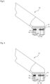
- Fig. 4 shows a cross section of the vacuum cleaner nozzle 10 on soft floor.
- the friction between the block 16 and the cleaned surface is higher than in case of hard floor.
- the tension of springs 14 is relatively high and the displacement of the block 16 inside the cavity 13 is greater in comparison to the hard floor.
- the slot between the channel 18 of the block 16 and the suction channel 12 of the nozzle 10 is smaller in comparison to the hard floor so the air pressure value is changed to allow the easy manoeuvring of the nozzle 10 on soft floor by the user.
- Fig. 5 shows a cross section of the vacuum cleaner nozzle 10 with the block 16 with holes 19.
- the nozzle 10 is on the soft floor.
- the block 16 has holes 19 instead of the channel 18 (not shown on this figure).
- the block 16 has two through holes 19 of trapezoidal shape. In the neutral position blocks 16 are centred in the cavity of the suction channel 12 and holes 19 are hidden.
- the nozzle 10 moves on the cleaned surface forward and backward the appropriate friction occurs between the friction area 20 and the cleaned surface and the block 16 are displaced from the basic neutral position and holes 19 open and limit the air coming through the suction channel 12 and reduce the suction pressure value.
- the present invention enables a nozzle for a vacuum cleaner with suction pressure control system which adjust the suction pressure depending on the type of the cleaning surface i.e. hard or soft surface.
- the present invention enables a device which adjust the suction pressure automatically thanks to which the maneuvering of the nozzle is easy and comfortable for the user.
- the nozzle provides a great cleaning results regardless the type of cleaning surface.
Landscapes
- Engineering & Computer Science (AREA)
- Mechanical Engineering (AREA)
- Nozzles For Electric Vacuum Cleaners (AREA)
Abstract
A nozzle (10) for a vacuum cleaner with suction unit, wherein the nozzle (10) comprises a housing (11), a suction channel (12) and a suction pressure control system, wherein the suction pressure control system comprises at least one cavity (13) for receiving a block (16) which is movably mounted inside the cavity (13) for suction pressure regulation depending on a type of a cleaning surface.The present invention enables a nozzle for a vacuum cleaner with suction pressure control system which adjust the suction pressure depending on the type of the cleaning surface i.e. hard or soft surface. The present invention enables a device which adjust the suction pressure automatically thanks to which the maneuvering of the nozzle is easy and comfortable for the user. The nozzle provides a great cleaning results regardless the type of cleaning surface.
Description
- The present invention relates to a nozzle for a vacuum cleaner having a suction unit, wherein the nozzle comprises a housing, a suction channel and a suction pressure control system.
- Vacuum cleaners with a cleaning power control in dependence with the type of floor are well known from the state of the art. There are known vacuum cleaners with a manual setting of the type of the cleaned surface. More advanced vacuum cleaners are equipped with a different kind of sensors which senses the type of the cleaning surface and adjust the optimal working power in a way that provides an easy maneuvering of the suction nozzle together with reaching great cleaning results.
- The patent document
US 2 894 274 A discloses a suction cleaning tool comprising a nozzle body having an outlet communicating with a source of suction, means defining a nozzle mouth in said body communicating with said outlet and having lips for engagement with a yieldable surface to be cleaned whereby suction in said mouth draws the surface above the plane of said nozzle lips, means defining a port in said body for passage of outside air into said body to reduce the suction pressure at said nozzle mouth, valve means normally closing said port, surface engageable means movably mounted on said body and connected to said valve means, said surface engageable means disposed in said nozzle mouth substantially in the plane of said nozzle lips and of smaller area than the area of said nozzle mouth to at all times allow passage of air therepast: into said mouth to thereby substantially eliminate the effects of suction pressure thereon, and said surface engageable means actuated by engagement with the yieldable surface, upon the latter being drawn inwardly of said nozzle lips, to shift said valve means to uncover said port for dmission of outside air into said body, whereby the suction pressure at said nozzle lips is lessened to reduce the force required to move the tool over the surface being cleaned. - The patent document
US 2019 / 090 704 A1 discloses a vacuum cleaner which basically includes a motor, first and second inlets and a cover. The motor is configured to create flow through a suction path. The first inlet and the second inlet are disposed in the housing in fluid communication with the suction path. A cover is pivotably disposed in the second inlet. The cover is movable between a first position in which the second inlet is substantially covered to substantially prevent fluid from flowing through the second inlet and a second position in which fluid is allowed to flow through the second inlet. - The patent document
US 2005 / 160 556 A1 discloses a floor care apparatus has a nozzle assembly housing an agitator. A motor couples to the agitator to drive it at two or more speeds and constant suction power. A user indicates their mode-of-operation preference by positioning a switch. An agitator motor control circuit, responsive to the switch, effectuates motor control by supplying either a fixed duty cycle signal of a substantially constant voltage value that is on for a first or fist and second of four quarters of the waveform period. Thereafter, it repeats for additional periods. The switch preferably embodies a resistor network and a fixed current source that creates a voltage input to an A/D converter that falls within a specific range. Other apparatus embodiments contemplate multiple agitators with one or more agitator motors. A suction fan motor, separate from the agitator motor(s), may also exist. - It is the object of the present invention to provide a vacuum cleaner provided with a nozzle which has a suction pressure control system depending on the type of the cleaning surface i.e. hard floor or soft surface which system provides adjustment of the suction pressure according to the floor type.
- It is the object of the present invention to provide a nozzle for a vacuum cleaner which is easy to maneuver and thanks to which the user can obtain a great cleaning results on hard and soft surfaces without user attention to the device settings.
- The object is solved by a nozzle for vacuum cleaner with the suction pressure control system comprising at least one cavity for receiving a block which is movably mounted inside the cavity for suction pressure regulation depending on type of a cleaning surface. The suction pressure control system is for adjusting the suction pressure in dependence of the type of the cleaning surface. The cavity is an element of a suction channel and it is designed to receive a block. Advantageously, there are two cavities placed at the both sides of the suction channel. Each cavity has one block. The block is an element made out of plastic or metal. Each block is movably mounted inside the cavity what means that the position of the block can be changed in relation to the suction channel of the nozzle but the movement of the block is limited to the size of the cavity in which the block is placed. Changing of the position of the block is realized automatically depending the type of a cleaning surface - hard floor and soft floor e.g. carpet because of different friction between the nozzle and the cleaning surface. The air pressure regulation is performed by positioning of each block in relation to the suction channel of the nozzle.
- In a preferred embodiment of the invention the cavity is a part of the suction channel. The cavity is a deepen area of the suction channel inside of which the block is positioned. Advantageously, there are two cavities at two sides of the nozzle suction channel.
- In another embodiment of the invention the block is a D-shape element which has two rounded areas on the front and rear side of the block. The rounded areas of the block are facing the cleaning surface and the rounded areas are provided in order to facilitate the movement of the block on the cleaning surface. The rounded areas of the block are placed on the front and rear side of the block in order to facilitate the movement of the nozzle forward and backward the user.
- In another embodiment of the invention the block has two rounded areas placed on the left and right side of the block. Such positioning of the rounded areas are provided to reduce the force needed to move the nozzle in different way then forward and backward e.g. the biased movement of the nozzle or the side movement of the nozzle.
- Advantageously, the block is mounted inside the cavity by rails and springs. In order to enable the movement of the block inside the cavity, the block is mounted by rails and springs. Each cavity has two rails and two springs. The springs allow the block to move in horizontal direction and the rails prevents the movement of the block in the vertical direction.
- In another embodiment of the invention the block has a friction area. The friction area is placed at the bottom side of the block and is in constant contact with the cleaning surface. Depending on the type of the cleaning surface i.e. the hard floor or the soft floor the friction between the surface and the block is different resulting the difference movement - bigger or smaller movement of the block in relation to the suction channel of the vacuum cleaner nozzle.
- Advantageously, the block has a channel through which air with dust passes. The channel is placed at the bottom side of the block which is faced toward the cleaned surface. The air passes through the channel which creates with the suction channel a passage for the air. Created passage size depends on the type of the cleaning surface as the friction between the block and the surface is different depending on the surface type.
- In another embodiment of the invention the block has two through holes and the holes have a trapezoidal shape. The through holes of trapezoidal shape replaces the channel of the previous embodiments of the invention. The trapezoidal shape holes reduce the suction pressure which corresponds to the depth of the holes opened. The positive effect of using the trapezoidal shape is that change of the pressure is obtained gradually in dependence of the depth of the holes opened. The change of the pressure value is undetectable and further convenient for the user.
- The shape of the through holes is not limited to the trapezoidal shape. The holes can be designed of a rectangular, oval or irregular shape.
- The present invention enables a nozzle for a vacuum cleaner with suction pressure control system which adjust the suction pressure depending on the type of the cleaning surface i.e. hard or soft surface. The present invention enables a device which adjust the suction pressure automatically thanks to which the maneuvering of the nozzle is easy and comfortable for the user. The nozzle provides a great cleaning results regardless the type of cleaning surface.
- The construction of the invention, however, together with additional objects and corresponding advantages will be best understood from the following description of specific embodiments and in connection with the accompanying drawing.
- In the drawing:
- Fig. 1
- shows a vacuum cleaner nozzle bottom view,
- Fig. 2
- shows a vacuum cleaner nozzle cross section with the block in a neutral position,
- Fig. 3
- shows a cross section of the vacuum cleaner nozzle on hard floor,
- Fig. 4
- shows a cross section of the vacuum cleaner nozzle on soft floor,
- Fig. 5
- shows a vacuum cleaner nozzle cross section with the block with holes on the soft floor.
- In cooperation with attached drawing, the technical contents and detailed description of the present invention are described thereinafter according to a preferable embodiment being not used to limit its executing scope. Any equivalent variation and modification made according to appended claims is all covered by the claims claimed by the present invention.
- In the following description of the preferred embodiments of the present invention, similar identical reference numbers designate identical of comparable components.
-
Fig. 1 shows anozzle 10 for a vacuum cleaner bottom view. Thenozzle 10 has ahousing 11 having asuction channel 12 for sucking up dirt from the cleaning surface. Thesuction channel 12 extends along the entire length of thehousing 11 of thenozzle 10. From thehousing 11 thesuction channel 12 goes to the pipe through which the dust sucked up goes to the vacuum cleaner (not shown on the figure). Thehousing 11 is a part of thenozzle 10 which contains all internal parts of the nozzle e.g. brush roller (not shown on the figure). - The
suction channel 12 has twocavities 13 for receiving ablock 16. Eachcavity 13 receives oneblock 16. Theblock 16 is a D-shape element which is mounted inside thecavity 13 by twosprings 14 and tworails 15.Springs 14 and rails 15 enables the movement of theblock 16 when thenozzle 10 moves forward and backward what means from the user and towards the user. Theblock 16 has two roundedareas 17 and onefriction area 20 at the bottom side of theblock 16. Tworounded areas 17 and afriction area 20 creates a D-shape of theblock 16. Therounded areas 17 are placed in the front and back side of theblock 16 which reduces the force needed to move thenozzle 10 forward and backward. -
Fig. 2 shows a cross section of the vacuumcleaner nozzle 10 with theblock 16 in a neutral position. The neutral position of theblock 16 is a position when thenozzle 10 is not working i.e. thenozzle 10 touches the cleaning surface but does not move on the surface. The In such neutral position theblock 16 is in the central position of thecavity 13. Spring 14 s are not stretched or compressed. Theblock 16 has achannel 18 through which the air passes. In the neutral position thechannel 18 does not cover thesuction channel 12 and the air flow which goes through thesuction channel 12 is not disturbed. -
Fig. 3 shows a cross section of the vacuumcleaner nozzle 10 on hard floor. When thenozzle 10 is on the hard floor the friction between thefriction area 20 of theblock 16 and the hard floor is relatively small so the tension of thesprings 14 is also small. Theblock 16 moves toward and backward and theblock 16 is moving inside thecavity 13 simultaneously according to the movement of thenozzle 10. When thenozzle 10 moves forward theblock 16 moves in opposite direction. During backward movement of thenozzle 10 theblock 16 also moves conversely. The slot which is created between thechannel 18 of theblock 16 and thesuction channel 12 is adjusted accordingly to reach desired air pressure value. The right pressure value means the pressure at which the manoeuvring of thenozzle 10 is optimal for the user. The right air pressure value for different kind of cleaning surfaces is different and has to be adjusted each time the type of the cleaning surface is changed i.e. the user start to vacuum the hard floor and next the soft floor e.g. a carpet. When thenozzle 10 is on the hard floor the friction is smaller than on the soft surface and the movement of theblock 16 is bigger and the air passage is bigger, the pressure is lower. -
Fig. 4 shows a cross section of the vacuumcleaner nozzle 10 on soft floor. When thenozzle 10 is on soft floor the friction between theblock 16 and the cleaned surface is higher than in case of hard floor. During the movement of thenozzle 10 on soft floor the tension ofsprings 14 is relatively high and the displacement of theblock 16 inside thecavity 13 is greater in comparison to the hard floor. The slot between thechannel 18 of theblock 16 and thesuction channel 12 of thenozzle 10 is smaller in comparison to the hard floor so the air pressure value is changed to allow the easy manoeuvring of thenozzle 10 on soft floor by the user. -
Fig. 5 shows a cross section of the vacuumcleaner nozzle 10 with theblock 16 withholes 19. Thenozzle 10 is on the soft floor. To provide the air pressure value change in relation to the type of the cleaning surface theblock 16 hasholes 19 instead of the channel 18 (not shown on this figure). Theblock 16 has two throughholes 19 of trapezoidal shape. In the neutral position blocks 16 are centred in the cavity of thesuction channel 12 and holes 19 are hidden. When thenozzle 10 moves on the cleaned surface forward and backward the appropriate friction occurs between thefriction area 20 and the cleaned surface and theblock 16 are displaced from the basic neutral position and holes 19 open and limit the air coming through thesuction channel 12 and reduce the suction pressure value. - The present invention enables a nozzle for a vacuum cleaner with suction pressure control system which adjust the suction pressure depending on the type of the cleaning surface i.e. hard or soft surface. The present invention enables a device which adjust the suction pressure automatically thanks to which the maneuvering of the nozzle is easy and comfortable for the user. The nozzle provides a great cleaning results regardless the type of cleaning surface.
-
- 10
- nozzle
- 11
- housing
- 12
- suction channel
- 13
- cavity
- 14
- spring
- 15
- rail
- 16
- block
- 17
- rounded area
- 18
- channel
- 19
- hole
- 20
- friction area
Claims (10)
- A nozzle (10) for a vacuum cleaner with suction unit, wherein the nozzle (10) comprises a housing (11), a suction channel (12) and a suction pressure control system, characterized in that the suction pressure control system comprises at least one cavity (13) for receiving a block (16) which is movably mounted inside the cavity (13) for suction pressure regulation depending on a type of a cleaning surface.
- The nozzle (10) according to claim 1, characterized in that the cavity (13) is a part of the suction channel (12).
- The nozzle (10) according to any of the preceding claims, characterized in that the block (16) is a D-shape element.
- The nozzle (10) according to any of the preceding claims, characterized in that the block (16) has two rounded areas (17) on its front and rear side.
- The nozzle (10) according to claims 1-3, characterized in that the bock (16) has two rounded areas (17) on its left and right side.
- The nozzle (10) according to any of the preceding claims, characterized in that the block (16) is mounted inside the cavity (13) by rails (15) and springs (14).
- The nozzle (10) according to any of the preceding claims, characterized in that the block (16) has a friction area (20).
- The nozzle (10) according to any of the preceding claims, characterized in that the block (16) has a channel (18) through which air with dust passes.
- The nozzle (10) according to any of preceding claims 1-7 characterized in that the block (16) has two through holes (19).
- The nozzle (10) according to claim 9, characterized in that the holes (19) have a trapezoidal shape.
Priority Applications (1)
| Application Number | Priority Date | Filing Date | Title |
|---|---|---|---|
| EP23155005.4A EP4410168A1 (en) | 2023-02-04 | 2023-02-04 | Nozzle for vacuum cleaner with pressure regulating block |
Applications Claiming Priority (1)
| Application Number | Priority Date | Filing Date | Title |
|---|---|---|---|
| EP23155005.4A EP4410168A1 (en) | 2023-02-04 | 2023-02-04 | Nozzle for vacuum cleaner with pressure regulating block |
Publications (1)
| Publication Number | Publication Date |
|---|---|
| EP4410168A1 true EP4410168A1 (en) | 2024-08-07 |
Family
ID=85175778
Family Applications (1)
| Application Number | Title | Priority Date | Filing Date |
|---|---|---|---|
| EP23155005.4A Pending EP4410168A1 (en) | 2023-02-04 | 2023-02-04 | Nozzle for vacuum cleaner with pressure regulating block |
Country Status (1)
| Country | Link |
|---|---|
| EP (1) | EP4410168A1 (en) |
Citations (7)
| Publication number | Priority date | Publication date | Assignee | Title |
|---|---|---|---|---|
| US2894274A (en) | 1956-10-29 | 1959-07-14 | Hoover Co | Suction control in surface cleaning tool |
| DE1844732U (en) * | 1961-10-19 | 1962-01-11 | Herbert Schmidt | MOUTH PIECE FOR VACUUM CLEANER. |
| JP3623632B2 (en) * | 1997-03-14 | 2005-02-23 | アズマ工業株式会社 | Vacuum cleaner vacuum cleaner with wiping function |
| US20050160556A1 (en) | 2004-01-23 | 2005-07-28 | Hitzelberger J. E. | Floor care apparatus with multiple agitator speeds and constant suction power |
| DE102016109287A1 (en) * | 2016-05-20 | 2017-11-23 | Vorwerk & Co. Interholding Gmbh | Floor nozzle for a vacuum cleaning device |
| US20190090704A1 (en) | 2017-09-26 | 2019-03-28 | Zenith Technologies, Llc | Vacuum cleaner having hinged inlet cover |
| US10980381B1 (en) * | 2017-10-12 | 2021-04-20 | Matthew ZUSY | Nozzle assembly for vacuum device |
-
2023
- 2023-02-04 EP EP23155005.4A patent/EP4410168A1/en active Pending
Patent Citations (7)
| Publication number | Priority date | Publication date | Assignee | Title |
|---|---|---|---|---|
| US2894274A (en) | 1956-10-29 | 1959-07-14 | Hoover Co | Suction control in surface cleaning tool |
| DE1844732U (en) * | 1961-10-19 | 1962-01-11 | Herbert Schmidt | MOUTH PIECE FOR VACUUM CLEANER. |
| JP3623632B2 (en) * | 1997-03-14 | 2005-02-23 | アズマ工業株式会社 | Vacuum cleaner vacuum cleaner with wiping function |
| US20050160556A1 (en) | 2004-01-23 | 2005-07-28 | Hitzelberger J. E. | Floor care apparatus with multiple agitator speeds and constant suction power |
| DE102016109287A1 (en) * | 2016-05-20 | 2017-11-23 | Vorwerk & Co. Interholding Gmbh | Floor nozzle for a vacuum cleaning device |
| US20190090704A1 (en) | 2017-09-26 | 2019-03-28 | Zenith Technologies, Llc | Vacuum cleaner having hinged inlet cover |
| US10980381B1 (en) * | 2017-10-12 | 2021-04-20 | Matthew ZUSY | Nozzle assembly for vacuum device |
Similar Documents
| Publication | Publication Date | Title |
|---|---|---|
| KR100443091B1 (en) | A power-controlled vacuum cleaner according to the operation mode of the electric brush | |
| US5457848A (en) | Recirculating type cleaner | |
| US4864682A (en) | Self-adjusting wiper strip assembly for a vacuum cleaner | |
| US5930864A (en) | Upright vacuum cleaner | |
| KR200239294Y1 (en) | Air gun for many talent | |
| EP3808242A1 (en) | Garden power tool and control method therefor | |
| CN223299020U (en) | Dust collector device and dust collector system | |
| KR101487791B1 (en) | Suction flow speed control apparatus and vacuum cleaner having the same | |
| EP4410168A1 (en) | Nozzle for vacuum cleaner with pressure regulating block | |
| US5747764A (en) | Electric power switch for a vacuum cleaner which has a suction control function | |
| JP4816384B2 (en) | Vacuum cleaner suction tool and vacuum cleaner using the same | |
| KR101932074B1 (en) | Vacuum cleaner and control method for the same | |
| EP3758571B1 (en) | A cleaner head | |
| CN221511772U (en) | A cleaning robot for preventing water from entering a fan | |
| JPH06292646A (en) | Sucking tool for sucking cleaner | |
| JP2000041912A (en) | Electric vacuum cleaner | |
| JP7495204B2 (en) | Vacuum cleaner | |
| US11786090B2 (en) | Floor nozzle for a vacuum cleaner and vacuum cleaner | |
| CN221013159U (en) | Universal dust box device and cleaning equipment | |
| KR900000116Y1 (en) | Suction force adjusting device of vacuum cleaner | |
| JP2006055379A (en) | Electric vacuum cleaner | |
| KR200161350Y1 (en) | Vacuum cleaner | |
| JP2705800B2 (en) | Vacuum cleaner floor nozzle | |
| KR200152449Y1 (en) | Suction brush with flow rate control | |
| KR200172942Y1 (en) | Indraft assembly for vacuum cleaner |
Legal Events
| Date | Code | Title | Description |
|---|---|---|---|
| PUAI | Public reference made under article 153(3) epc to a published international application that has entered the european phase |
Free format text: ORIGINAL CODE: 0009012 |
|
| STAA | Information on the status of an ep patent application or granted ep patent |
Free format text: STATUS: THE APPLICATION HAS BEEN PUBLISHED |
|
| AK | Designated contracting states |
Kind code of ref document: A1 Designated state(s): AL AT BE BG CH CY CZ DE DK EE ES FI FR GB GR HR HU IE IS IT LI LT LU LV MC ME MK MT NL NO PL PT RO RS SE SI SK SM TR |
|
| STAA | Information on the status of an ep patent application or granted ep patent |
Free format text: STATUS: REQUEST FOR EXAMINATION WAS MADE |
|
| 17P | Request for examination filed |
Effective date: 20250207 |