EP4408288B1 - Dammsonde - Google Patents
Dammsonde Download PDFInfo
- Publication number
- EP4408288B1 EP4408288B1 EP22798272.5A EP22798272A EP4408288B1 EP 4408288 B1 EP4408288 B1 EP 4408288B1 EP 22798272 A EP22798272 A EP 22798272A EP 4408288 B1 EP4408288 B1 EP 4408288B1
- Authority
- EP
- European Patent Office
- Prior art keywords
- probe
- perineal
- perineal probe
- flared portion
- plane
- Prior art date
- Legal status (The legal status is an assumption and is not a legal conclusion. Google has not performed a legal analysis and makes no representation as to the accuracy of the status listed.)
- Active
Links
Images


Classifications
-
- A—HUMAN NECESSITIES
- A61—MEDICAL OR VETERINARY SCIENCE; HYGIENE
- A61B—DIAGNOSIS; SURGERY; IDENTIFICATION
- A61B5/00—Measuring for diagnostic purposes; Identification of persons
- A61B5/68—Arrangements of detecting, measuring or recording means, e.g. sensors, in relation to patient
- A61B5/6846—Arrangements of detecting, measuring or recording means, e.g. sensors, in relation to patient specially adapted to be brought in contact with an internal body part, i.e. invasive
- A61B5/6847—Arrangements of detecting, measuring or recording means, e.g. sensors, in relation to patient specially adapted to be brought in contact with an internal body part, i.e. invasive mounted on an invasive device
-
- A—HUMAN NECESSITIES
- A61—MEDICAL OR VETERINARY SCIENCE; HYGIENE
- A61B—DIAGNOSIS; SURGERY; IDENTIFICATION
- A61B5/00—Measuring for diagnostic purposes; Identification of persons
- A61B5/22—Ergometry; Measuring muscular strength or the force of a muscular blow
- A61B5/224—Measuring muscular strength
- A61B5/227—Measuring muscular strength of constricting muscles, i.e. sphincters
-
- A—HUMAN NECESSITIES
- A61—MEDICAL OR VETERINARY SCIENCE; HYGIENE
- A61B—DIAGNOSIS; SURGERY; IDENTIFICATION
- A61B5/00—Measuring for diagnostic purposes; Identification of persons
- A61B5/24—Detecting, measuring or recording bioelectric or biomagnetic signals of the body or parts thereof
- A61B5/25—Bioelectric electrodes therefor
- A61B5/251—Means for maintaining electrode contact with the body
-
- A—HUMAN NECESSITIES
- A61—MEDICAL OR VETERINARY SCIENCE; HYGIENE
- A61B—DIAGNOSIS; SURGERY; IDENTIFICATION
- A61B5/00—Measuring for diagnostic purposes; Identification of persons
- A61B5/24—Detecting, measuring or recording bioelectric or biomagnetic signals of the body or parts thereof
- A61B5/25—Bioelectric electrodes therefor
- A61B5/279—Bioelectric electrodes therefor specially adapted for particular uses
- A61B5/296—Bioelectric electrodes therefor specially adapted for particular uses for electromyography [EMG]
-
- A—HUMAN NECESSITIES
- A61—MEDICAL OR VETERINARY SCIENCE; HYGIENE
- A61B—DIAGNOSIS; SURGERY; IDENTIFICATION
- A61B5/00—Measuring for diagnostic purposes; Identification of persons
- A61B5/24—Detecting, measuring or recording bioelectric or biomagnetic signals of the body or parts thereof
- A61B5/316—Modalities, i.e. specific diagnostic methods
- A61B5/389—Electromyography [EMG]
- A61B5/391—Electromyography [EMG] of genito-urinary organs
-
- A—HUMAN NECESSITIES
- A61—MEDICAL OR VETERINARY SCIENCE; HYGIENE
- A61B—DIAGNOSIS; SURGERY; IDENTIFICATION
- A61B5/00—Measuring for diagnostic purposes; Identification of persons
- A61B5/43—Detecting, measuring or recording for evaluating the reproductive systems
- A61B5/4306—Detecting, measuring or recording for evaluating the reproductive systems for evaluating the female reproductive systems, e.g. gynaecological evaluations
- A61B5/4318—Evaluation of the lower reproductive system
- A61B5/4337—Evaluation of the lower reproductive system of the vagina
-
- A—HUMAN NECESSITIES
- A61—MEDICAL OR VETERINARY SCIENCE; HYGIENE
- A61B—DIAGNOSIS; SURGERY; IDENTIFICATION
- A61B90/00—Instruments, implements or accessories specially adapted for surgery or diagnosis and not covered by any of the groups A61B1/00 - A61B50/00, e.g. for luxation treatment or for protecting wound edges
- A61B90/06—Measuring instruments not otherwise provided for
-
- A—HUMAN NECESSITIES
- A61—MEDICAL OR VETERINARY SCIENCE; HYGIENE
- A61N—ELECTROTHERAPY; MAGNETOTHERAPY; RADIATION THERAPY; ULTRASOUND THERAPY
- A61N1/00—Electrotherapy; Circuits therefor
- A61N1/02—Details
- A61N1/04—Electrodes
- A61N1/05—Electrodes for implantation or insertion into the body, e.g. heart electrode
- A61N1/0507—Electrodes for the digestive system
- A61N1/0512—Anal electrodes
-
- A—HUMAN NECESSITIES
- A61—MEDICAL OR VETERINARY SCIENCE; HYGIENE
- A61N—ELECTROTHERAPY; MAGNETOTHERAPY; RADIATION THERAPY; ULTRASOUND THERAPY
- A61N1/00—Electrotherapy; Circuits therefor
- A61N1/02—Details
- A61N1/04—Electrodes
- A61N1/05—Electrodes for implantation or insertion into the body, e.g. heart electrode
- A61N1/0521—Genital electrodes
- A61N1/0524—Vaginal electrodes
-
- A—HUMAN NECESSITIES
- A61—MEDICAL OR VETERINARY SCIENCE; HYGIENE
- A61N—ELECTROTHERAPY; MAGNETOTHERAPY; RADIATION THERAPY; ULTRASOUND THERAPY
- A61N1/00—Electrotherapy; Circuits therefor
- A61N1/18—Applying electric currents by contact electrodes
- A61N1/32—Applying electric currents by contact electrodes alternating or intermittent currents
- A61N1/36—Applying electric currents by contact electrodes alternating or intermittent currents for stimulation
- A61N1/36007—Applying electric currents by contact electrodes alternating or intermittent currents for stimulation of urogenital or gastrointestinal organs, e.g. for incontinence control
-
- A—HUMAN NECESSITIES
- A61—MEDICAL OR VETERINARY SCIENCE; HYGIENE
- A61B—DIAGNOSIS; SURGERY; IDENTIFICATION
- A61B90/00—Instruments, implements or accessories specially adapted for surgery or diagnosis and not covered by any of the groups A61B1/00 - A61B50/00, e.g. for luxation treatment or for protecting wound edges
- A61B90/06—Measuring instruments not otherwise provided for
- A61B2090/064—Measuring instruments not otherwise provided for for measuring force, pressure or mechanical tension
-
- A—HUMAN NECESSITIES
- A61—MEDICAL OR VETERINARY SCIENCE; HYGIENE
- A61B—DIAGNOSIS; SURGERY; IDENTIFICATION
- A61B2560/00—Constructional details of operational features of apparatus; Accessories for medical measuring apparatus
- A61B2560/04—Constructional details of apparatus
- A61B2560/0406—Constructional details of apparatus specially shaped apparatus housings
-
- A—HUMAN NECESSITIES
- A61—MEDICAL OR VETERINARY SCIENCE; HYGIENE
- A61B—DIAGNOSIS; SURGERY; IDENTIFICATION
- A61B2560/00—Constructional details of operational features of apparatus; Accessories for medical measuring apparatus
- A61B2560/04—Constructional details of apparatus
- A61B2560/0462—Apparatus with built-in sensors
- A61B2560/0468—Built-in electrodes
Definitions
- the invention relates to a perineal probe, and more particularly, a perineal diagnostic and rehabilitation probe. More broadly, the invention falls within the paramedical and medical field, the invention aims, in particular, to analyze the functional state of anatomical structures involved in the mechanism of continence and/or urinary and/or fecal incontinence.
- Continence is a complex mechanism that involves an acquired anticipatory reflex and an innate myotatic reflex that, in response to a stimulus, solicit several muscle groups.
- the stimulus corresponds to an increase in intra-abdominal pressure.
- the anticipatory reflex and the myotatic reflex cause muscle groups to contract in order to prevent urine and/or fecal leakage.
- a first group of muscles includes the urethral and anal sphincters which surround the urethra and the anal canal respectively. Under the effect of their respective contractions, the urethra and the anal canal close.
- the muscles of the perineum constitute a second group of muscles which participate in the mechanism of continence.
- the perineum is a set of muscles which extend from the pubis to the coccyx. Generally speaking, the perineum performs two functions, on the one hand, it maintains the abdominal contents: rectum, bladder, uterus, and on the other hand, it participates in the cushioning of abdominal hyperpressures and the closure of the bladder and rectum. In fact, the perineum is known to play an important role in the mechanism of continence.
- the first method of assessing the functional state of the perineum is a manual method that involves a vaginal or rectal examination. During this medical act, the therapist assesses the contraction initiated by the patient. According to this method, the assessment of the functional state of the perineum is carried out according to subjective criteria that are strongly correlated with the therapist's personal experience. In this context, neither diagnosis nor functional rehabilitation guarantee any regularity in the assessment of dysfunctions and the results of rehabilitation.
- Perineal probes are already known for the functional analysis and rehabilitation of anatomical structures involved in the mechanism of continence or incontinence. Alternative or similar devices are described in US 2018/055563 A1 , CN 113274028 A , FR 2827520 A1 , US 2019/160332 A1 And US 2013/018281 A1 .
- perineal probes known from the state of the art comprise a cylindrical probe body which has a rounded free end.
- the probe body comprises two annular electrodes arranged at a determined distance from each other.
- This type of perineal probe is designed to be introduced into the vaginal cavity of a patient and/or the anal cavity of a patient. Depending on their dimensions, this type of probe can cause feelings of discomfort when inserting and removing the probe from the vaginal or anal endocavity.
- this type of probe is generally designed for electrotherapy rehabilitation of the connective tissue surrounding the vagina and/or the anal cavity but also the muscles surrounding the vaginal or anal cavity.
- the annular nature of the electrodes does not allow the muscles to be isolated from each other in order to target the diagnosis or electrotherapy work.
- the cylindrical shape of the probe body does not allow this type of probe to be maintained in position during examinations or rehabilitation protocols. Indeed, this type of probe tends to come out of the endocavity when intra-abdominal pressure increases, which makes examinations or rehabilitation tedious. In this context, it is difficult to determine the functional state of the muscles surrounding the endocavity in an orthostatic or orthodynamic situation in the patient's daily life, which is likely to lead to urinary or fecal leakage.
- the document FR 2 941 860 describes another example of a perineal probe that is designed to be inserted into the vaginal cavity. This type of probe is used to measure the tone of the connective tissue surrounding the vaginal cavity.
- This perineal probe has two articulated and complementary branches. At least one branch has a curved end that covers the free end of the other branch to form a rounded probe head. Each branch carries a force sensor to determine the pendulum movement of the branches by a differential force measured between the front and rear sensor. After insertion of the probe into the vaginal cavity, the therapist applies a spacing of the branches arranged along an anteroposterior axis.
- the connective tissue When a small drop in force is measured on the front sensor, the connective tissue is of good quality and follows the movement of the branches. Conversely, when a significant drop in the measured force is measured, the connective tissue is of poor quality and follows the movement of the probe branches more slowly. Poor connective tissue quality is a known factor in incontinence. When the therapist obtains such a diagnosis, he can apply electrostimulation techniques that improve the trophicity and tone of the connective tissues.
- This type of probe is not particularly comfortable for patients and must be held in position by the therapist during the examination. In addition, this type of probe does not allow for a differentiated determination of dysfunction of the anatomical structures involved in the locking mechanism of the urethra or anal canal.
- the invention aims to overcome the drawbacks of the state of the art.
- the invention aims in particular to provide a perineal probe limiting feelings of discomfort both during its introduction into the vaginal or anal endocavity of the patient and during its use, or even during the removal of the perineal probe.
- the invention also aims to provide an endocavitary perineal probe that is held in position in the vaginal or anal endocavity during use.
- the invention aims to provide an endocavitary perineal probe that is held in position while the patient stands to perform physical movements that are likely to cause urinary or fecal leakage.
- the invention also aims to provide a diagnostic and/or rehabilitation tool capable of assessing the functional state and/or treating in a differentiated and asymmetrical manner the deep planes from the superficial planes of the perineum.
- the invention aims to provide a perineal probe which can adapt to the anatomical dimensions of a large number of patients.
- the perineal probe according to the invention is characterized in that, on the one hand, the flared portion comprises at least one side wall which has an internal face delimiting a conical internal volume of the flared portion, and on the other hand, the flared portion comprises at least one longitudinal groove which extends along a plane of symmetry of the perineal probe.
- the conformation of the body of the perineal probe which has a cylindrical lower part and a flared upper part, makes it possible to maintain the perineal probe in position while the patient performs exercises or movements in which urinary or fecal leaks occur on a daily basis. Furthermore, the deformable nature of the flared portion makes it possible to reduce the inconvenience associated with the introduction of the probe into the endocavity but also to press the flared portion against the walls of the endocavity once the perineal probe is in position in said endocavity.
- vaginal or anal endocavity is naturally collapsed; after its insertion into the endocavity, the flared portion unfolds and rests on the walls of the endocavity, said walls are thus collapsed against the underlying perineal muscles.
- the arrangement of the electronic organs on the lower part and/or on the upper part of the probe body makes it possible to target the muscles of the deep planes and/or the superficial planes of the perineum.
- the hollow nature of the flared portion and the longitudinal groove improve the amplitude of deformation of the flared portion.
- the longitudinal groove extends along a median sagittal plane of symmetry of the perineal probe and divides said at least one side wall into two half-walls.
- the flared portion comprises at least one groove that extends transversely relative to the median sagittal plane PSM of the perineal probe, said groove extending on the outer face of the side wall at a base disposed at the junction between the flared portion and the cylindrical portion. Said groove reduces the thickness of the side wall at its base in order to increase the amplitude of folding of the flared portion.
- the perineal probe may include a holding member that is movable between a deployed position and a folded position, wherein in the deployed position, the holding member allows the flared portion to be held in position in the patient's endocavity, and in the folded position, the holding member allows the perineal probe to be inserted into the endocavity.
- the lateral and top openings of the flared portion enhance the folding of the holding member, which is arranged, in the folded position, in the internal volume of the flared portion. This provides greater compactness of the head of the perineal probe for its introduction into the endocavity.
- the holding member may comprise a tab that extends in a projecting manner from the flared portion towards a free end, the tab being projecting along a plane of symmetry of the perineal probe.
- the tab can exert an elastic force against the wall of the endocavity. The elastic force then participates in maintaining the perineal probe within the endocavity.
- the tab exerts pressure on the anterior wall of the vagina or rectum so as to press this wall against the deep perineal muscles.
- the tab may comprise a striated surface at its free end. This striated surface can then cooperate with the wall of the endocavity which in the case of a vagina also comprises striates.
- the holding member can be attached to the cylindrical portion in a detachable manner.
- the tab can be protruding, in the deployed position, from the flared portion along an anteroposterior axis located on the plane. According to this arrangement, the tab exerts in the deployed position an anteroposterior force on the wall of the vaginal or anal endocavity which contributes to maintaining the perineal probe in position, in particular when the patient performs physical exercises to assess the functional state of the perineal muscles.
- the flared portion may extend at an angle of inclination ⁇ relative to a side wall of the cylindrical portion, the angle of inclination ⁇ being between 7° and 40°.
- the inclination of the flared portion corresponds to the natural anteroposterior inclination of the vagina. This inclination improves the maintenance of the perineal probe in the endocavity but also acts as a foolproof device, the perineal probe can then only be introduced into the endocavity in a single anteroposterior orientation.
- the flared portion comprises two electronic members arranged on either side of a plane of symmetry of the perineal probe. This arrangement makes it possible to interact in a differentiated manner with the muscles of the deep plane of the perineum which are located on either side of the endocavity.
- the cylindrical portion comprises two electronic members arranged on either side of a plane of symmetry of the perineal probe. This arrangement makes it possible to interact in a differentiated manner with the muscles of the superficial plane of the perineum which are located on either side of the endocavity.
- the cylindrical portion and the flared portion may respectively comprise electronic organs constituted by EMG electrodes, the electronic organs being arranged on either side of a median sagittal plane PSM of the perineal probe.
- EMG electrodes electronic organs constituted by EMG electrodes
- PSM median sagittal plane
- the electronic members may comprise two force sensors, the electronic members being arranged anteroposteriorly on either side of a median transverse plane PTM of the perineal probe. It is thus possible to measure, in isolation, the anteroposterior forces which are applied to the lower end of the endocavity.
- the present invention relates to a perineal probe 10.
- This perineal probe is designed for the diagnosis and rehabilitation of the perineum of a patient.
- the perineal probe 10 of the invention is configured to be at least partially introduced into the vaginal cavity of a patient.
- the perineal probe 10 can also be introduced into the anal cavity of a patient. This makes it possible in particular to treat male patients suffering from fecal incontinence.
- the term endocavity refers indifferently to the vaginal cavity and the anal cavity of a patient.
- the perineal probe 10 comprises a probe body which includes electronic members 110, 111, 112 configured to interact, through the walls of the endocavity, with muscles of the perineum of a patient.
- the probe body comprises a cylindrical portion 12 configured to be positioned at the lower end 201 of the endocavity of a patient.
- the probe body is made of a medical polymer material such as silicone or polyurethane.
- the selected polymer material has elasticity and sealing properties.
- the cylindrical portion 12 comprises a first end 120 and a second end 121 which are opposite each other.
- the first end 120 of the cylindrical portion 12 is free.
- the first end 120 defines the lower end of the perineal probe 10.
- the terms “low” and “lower” as well as their derivatives, when used specifically in reference to the perineal probe 10, designate the first longitudinal end 120 of the cylindrical portion 12.
- the second end 121 of the cylindrical portion 12 comprises an upper wall 124 which delimits the cylindrical portion 12 above.
- the cylindrical portion 12 comprises a first section and a second section.
- the cylindrical portion 12 may be equipped with an annular bead 123.
- the annular bead 123 is arranged at the junction between the first section and the second section of the cylindrical portion 12.
- the annular bead 123 makes it possible to match the anatomy of the patient at the opening of the endocavity.
- the bead annular 123 is placed in contact with the labia minora of the patient's vulva.
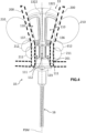
- the first section extends longitudinally between the annular bead 123 and the second end 121 of the cylindrical portion 12 (illustrated in figure 4 ).
- the first section can support electronic components 111, 112.
- the cylindrical portion 12 is delimited by a side wall 122.
- the second section of the cylindrical portion 12 extends from the annular bead 123 to the first end 120 of the cylindrical portion 12.
- the second section has dimensions smaller than the dimensions of the first section.
- the body of the perineal probe 10 also comprises a flared portion 13 which extends from an end 121 of the cylindrical portion 12 to a free apex 130.
- the free apex 130 of the flared portion 13 defines an upper longitudinal end of the perineal probe 10.
- the terms “top” and “upper” as well as their derivatives, when used specifically in reference to the perineal probe 10, designate the free end 130 of the flared portion.
- the body of the perineal probe 10 can measure between 5 cm and 15 cm between its lower end and its upper end.
- the flared portion 13 extends in a flared manner from the cylindrical portion 12 to a free apex 130 of the flared portion 13.
- the flared portion 13 comprises a base 131 arranged at the junction with the second end 121 of the cylindrical portion 12 of the probe body.
- the flared portion 13 extends from the base 131 to the free apex 130 of the flared portion 13. More precisely, the base 131 of the endocavity body 13 is integral with the upper face 124 of the cylindrical portion 12.
- the flared portion 13 constitutes the head of the perineal probe 10.
- the flared portion 13 is elastically deformable between a folded position and a deployed position.
- the head of the perineal probe 10 occupies a smaller volume which facilitates the insertion of the perineal probe 10 into the endocavity. The comfort of the patient is improved.
- the head of the probe in the deployed position, can rest on the walls of the endocavity. As a result, the perineal probe 10 is held in the endocavity of a patient by the flared portion 13 in the deployed position.
- vaginal or anal endocavity Since the vaginal or anal endocavity is naturally collapsed at rest, applying pressure to the walls of the endocavity makes it possible to bring these walls into contact with the anatomical structures surrounding the endocavity such as the muscles of the perineum.
- the flared portion 13 comprises at least one side wall 132.
- the side wall 132 extends in a flared manner from the base 131 towards the free top 130 of the flared portion 13.
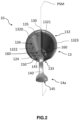
- the side wall 132 has an internal face 1320 which delimits a conical internal volume of the flared portion 13 (illustrated in figure 2 ).
- the flared portion 13 comprises at least one opening 133, 134 arranged along a plane of symmetry of the perineal probe 10.
- the opening(s) facilitate the elastic deformation of the flared portion 13 for a more comfortable introduction of the probe into the endocavity.
- the flared portion 13 comprises a lateral opening 133 and a top opening 134.
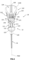
- the lateral opening 133 is arranged according to a plane of symmetry of the perineal probe 10. As illustrated in figure 6 , the lateral opening 133 extends longitudinally on either side of a median sagittal plane PSM of the perineal probe 10.
- the median sagittal plane shown in Figures 1 to 4 And 6 defines a longitudinal plane of symmetry according to a sagittal orientation of the perineal probe 10.
- the lateral opening 133 extends from the base 131 of the head to the free summit 130 of the perineal probe 10.
- the lateral opening 133 has a U shape which extends from the base 131, the branches of the U move apart from each other up to the top 130 so as to form a flared lateral opening 133.
- the top opening 134 is arranged at the level of the free top 130 of the flared portion 13. As illustrated in figure 2 , the summit opening 134 is symmetrical with respect to the sagittal median plane PSM of the perineal probe 10.
- the side wall 133 comprises a summit bead 1323 which at least partially delimits the summit opening 134.
- the summit bead 1323 contributes to the comfort of the patient during the introduction of the perineal probe 10 into the endocavity.
- the top opening 134 extends in a secant plane of the lateral opening 133, the two openings 133, 134 being arranged in continuity with each other along a median sagittal axis of the perineal probe 10.
- the median sagittal axis is arranged in the PSM plane of the perineal probe 10.
- the flared portion 13 comprises at least one groove 135, 136, 137.
- Each groove 135, 136, 137 increases the amplitude of the elastic deformation of the flared portion 13.
- the flared portion 13 comprises a longitudinal groove 135 which extends along the median sagittal plane PSM.
- the longitudinal groove 135 divides the flared portion 13 into two half-walls 1321, 1322 along the median sagittal plane PSM of the perineal probe 10.
- the groove 135 extends at least partially between the base 131 and the free apex 130 of the flared portion 13. In the example illustrated in figure 2 , there groove 135 extends over the entire height of the flared portion 13 between the base 131 and the free top 130.
- the two half-walls 1321, 1322 are curved so as to form a corolla.
- the half-walls 1321, 1322 are curved convexly relative to the median sagittal plane PSM.
- the therapist can then move the flared portion 13 from its deployed position to the folded position by pinching the half-walls 1321, 1322 in order to fold the head of the perineal probe 10 along the median sagittal plane PSM.
- the longitudinal groove 135 makes it possible to increase the amplitude of the folding of the head of the perineal probe 10.
- the flared portion 13 comprises at least one groove 136, 137 which extends at the base 131 on the outer face of the side wall 132.
- the groove or grooves 136, 137 extend transversely relative to the median sagittal plane PSM over at least part of the circumference of the base 131 of the flared portion 13.
- These grooves 136, 137 reduce the thickness of the side wall 132 in order to increase the folding amplitude of the flared portion 13.
- the flared portion 13 comprises two transverse grooves 136, 137 which are symmetrical relative to the median sagittal plane PSM.
- the two transverse grooves 136, 137 define a plane perpendicular to the median sagittal plane PSM.
- the flared portion 13 extends at an angle of inclination ⁇ relative to a side wall 122 of the cylindrical portion 12.
- the angle of inclination ⁇ can be between 7° and 40°; the angle of inclination ⁇ can also be between 15° and 30°.
- the inclination of the flared portion 13 makes it possible to adapt the conformation of the perineal probe 10 to the natural anteroposterior inclination of the vagina relative to the pelvic floor.
- the inclination of the flared portion 13 makes it possible to improve the comfort of the patient and to maintain the position of the perineal probe 10.
- the inclination of the flared portion 13 acts as a foolproofing device so that the therapist inserts the perineal probe 10 in the correct anteroposterior orientation.
- the perineal probe 10 comprises a holding member 14a, 14b.
- the holding member 14a, 14b is configured to bear on the wall of the endocavity in order to improve the holding in position of the perineal probe 10.
- the holding member 14a, 14b is movable between a deployed position and a folded position. In the deployed position, the holding member 14a, 14b projects from the body of the perineal probe 10 and bears on a wall of the endocavity of the patient in order to hold the perineal probe 10 in position adequate.
- the folded position of the holding member 14a, 14b allows the introduction of the perineal probe 10 into the endocavity.
- the holding member 14a, 14b comprises a tab 140 which extends in a projecting manner from the flared portion 13 towards a free end 141.
- the tab 140 projects along the median sagittal plane PSM of the perineal probe 10.
- the tab 140 is elastically deformable in the same way as the flared portion 13.
- the tab 140 can be made of the same material as the body of the perineal probe 10.
- the tab 140 is detachably attached to the cylindrical portion 12 of the perineal probe 10. This makes it possible to use several sizes of tabs 140 depending on the anatomy of the patient. As is known, the depth of a vagina can vary from one woman to another on average between 7 and 15 cm. The therapist can then choose the size of the tab 140 depending on the anatomy of the patient.
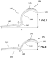
- FIGs 7 and 8 illustrate two sizes of tabs 140 for the holding member 14a, 14b.
- the figure 5 provides a schematic representation of the perineal probe 10 which fictitiously carries two holding members 14a, 14b in order to be able to appreciate the difference in size of the tab 140 of each holding member 14a, 14b.
- the tab 140 can be broken down into three segments. At a first end, the tab 140 comprises a fixing segment 142.
- the fixing segment 142 is configured to cooperate with complementary receiving means 15 which are arranged on the body of the perineal probe 10.
- the complementary receiving means 15 are arranged on the body of the perineal probe 10 according to the PSM plane.
- the complementary receiving means 15 comprise a slot 150 whose opening is provided on the upper face 124 of the cylindrical portion 12.
- the slot 150 is arranged along the median sagittal plane PSM.
- the tab 140 can extend along this same plane and in the same axis as the lateral opening 133 of the endocavity body 13.
- the tab 140 projects, in the deployed position, from the flared portion 13 along an anteroposterior axis located on the plane PSM.
- This arrangement on the plane PSM also makes it possible to fold, through the lateral opening 133, the tab 140 into the internal volume of the flared portion 13.
- the tab 140 is folded by elastic deformation into the internal volume of the flared portion 13.
- the fixing segment 142 is straight and of rectangular section in order to cooperate with the slot 150.
- the dimensions of the fixing segment 142 are complementary to those of the slot 150.
- the sections of the slot 150 and of the fixing segment 142 may have other shapes such as a circular, hexagonal, triangular shape etc.
- the complementary receiving means 15 comprise a notch 151 formed on the side wall 122 of the cylindrical portion 12.
- the notch 151 is arranged on the PSM plane.
- the notch 151 is complementary to the section of the fixing segment 142 in order to maintain the holding member 14a, 14b during use of the perineal probe 10.
- the notch 151 forms a locking groove in which the fixing segment 142 is inserted and placed in abutment against the bottom of the notch 151.
- the perineal probe 10 does not include any anteroposterior electronic organs 112.
- the complementary receiving means 15 may also take other forms such as clips or any other type of mechanical receiving means allowing the holding member 14a, 14b to be removably fixed.
- the detachable nature of the holding member 14a, 14b makes it possible to sterilize the perineal probe 10 after use or to choose a tab 140 suitable for the anatomy of the patient.
- the tab 140 comprises an offset segment 143.
- the offset segment 143 extends the fixing segment 142 towards the free end 141.
- the offset segment 143 projects from the receiving means 15 so as to offset the tab 140 from the body of the perineal probe 10.
- the offset segment 143 is configured to move angularly away from the body of the perineal probe 10.
- the offset segment 143 is curved concavely relative to a central axis of the body of the perineal probe. The central axis extends from bottom to top in the PSM plane and is perpendicular to the upper face 124 of the cylindrical portion 12.
- the offset segment 143 has a radius of curvature ⁇ which can be more or less large depending on the different sizes of the holding member 14a, 14b.
- the holding member 14a of the figure 8 has a radius of curvature ⁇ greater than the radius of curvature ⁇ of the holding member 14b of the figure 7 .
- the tab 140 also comprises a support segment 144.
- the support segment 144 extends between the offset segment 143 and the free end 141 of the tab 140.
- the support segment 144 is configured to bear on a wall of the endocavity when the perineal probe 10 is introduced into the endocavity.
- the support segment 144 comprises a striated surface 145.
- the striated surface 145 of the tab 140 allows better adhesion to the vaginal wall which itself has striates.
- the striated surface 145 improves maintaining the perineal probe 10 in position during a diagnostic protocol or a rehabilitation protocol.
- the striated surface 145 is arranged on an oval portion of the support segment 144.
- the oval portion has a surface curvature in the manner of the back of a spoon.
- the surface curvature improves the contact of the striated surface 145 with the vaginal wall.
- the oval portion of the support segment 144 is arranged in the internal volume of the flared portion 13. In this folded position, the oval portion of the support segment 144 is complementary to the half-walls 1321, 1322 in the folded position.
- the support segment 144 and the half-walls 1321, 1322 then form an insertion head whose rounded profile facilitates the introduction of the perineal probe 10 into the endocavity. Consequently, before the introduction of the perineal probe 10 into the endocavity of a patient, the therapist moves the holding member 14a, 14b into the folded position before exerting pressure on each half-wall 1321, 1322 in order to move the flared portion 13 into the folded position.
- the elastic properties of the tab 140 and the curvature of the offset segment 143 make it possible to block the perineal probe 10 in position by exerting an anteroposterior elastic force against the wall of the endocavity.
- This anteroposterior effort prevents the perineal probe 10 from being expelled from the endocavity when the patient performs a physical exercise to assess the functional state and/or to treat the deep planes from the superficial planes of the perineum in a differentiated and asymmetrical manner.
- the dimensions of the holding members 14a, 14b may be different depending on the height H of the tab 140 but also depending on the distance d which corresponds to the offset of the free end 141 relative to the fixing segment 142. More particularly, the radius of curvature ⁇ of the offset segment 143 and the length of the support segment 144 may have different dimensions in order to provide several holding members 14a, 14b of different sizes. In the example of the figure 7 , the support segment 144 of the holding member 14b is longer than the support segment of the holding member 14a of the figure 8 .
- the electronic components 110, 111, 112 are arranged on the flared portion 13 and/or on the cylindrical portion 12.
- the perineal probe 10 comprises power supply cables 16 for the electronic components 110, 111, 112.
- the cylindrical portion 12 comprises at least one longitudinal passage enabling the power supply cables 16 to be integrated into the cylindrical portion 12 of the perineal probe 10.
- said at least one longitudinal passage extends from the free end 120 of the cylindrical portion 12 to a point of contact with each electronic member 110, 111, 112.
- the power cables 16 connect each electronic member 110, 111, 112 to an electronic control unit.
- the electronic control unit is capable of managing each electronic member 110, 111, 112 in a differentiated manner.
- the electronic control unit may consist of a computer or any other electronic terminal configured to store and execute a program for managing the electronic members 110, 111, 112 of the perineal probe 10.
- figure 2 shows two pads 160 at the junction between each half-wall 1321, 1322 and the upper face 124 of the cylindrical portion 12. These pads 160 respectively provide a chamber in which the contactors of the electric cables 16 are connected to the contactors of the electronic components 110, 111, 112.
- the perineal probe 10 may comprise a rechargeable battery powering the electronic organs 110, 111, 112, remote transmission means (for example etc.) and an electronic control unit for the electronic organs 110, 111, 112.
- the remote transmission means may consist of a near-field transmitter/receiver of the radio, Bluetooth, Wifi, NFC, RFID etc. type.
- the electronic control unit may comprise a clock, a processor and a memory capable of storing and executing data and algorithms such as a diagnostic program and/or a rehabilitation program previously loaded into the memory.
- the electronic members 110, 111 are arranged two by two on either side of the median sagittal plane PSM.
- each electronic member 110, 111 comprises an EMG electrode respectively.
- EMG Electrometic
- the electronic members 112 are arranged on the cylindrical portion 12.
- the electronic members 112 are arranged two by two, in an anteroposterior manner, on either side of a median transverse plane PTM of the perineal probe 10.
- each electronic member 112 comprises a force sensor.
- the median transverse plane PTM shown in figure 5 defines a longitudinal plane of symmetry according to a transverse orientation of the perineal probe 10.
- the perineal probe 10 may comprise only the electronic members 110, 111 equipped with EMG electrodes or only the electronic members 112 constituted respectively by a force sensor. However, the perineal probe 10 may also associate all the electronic members 110, 111, 112 (see figure 4 ). In this case, the perineal probe 10 can operate in two modes: an EMG mode, in which only the electronic organs 110, 111 are active, and a force measurement mode, in which only the electronic organs 112 are active.
- the flared portion 13 comprises two electronic members 110 arranged on either side of a plane of symmetry of the perineal probe 10.
- the two electronic members 110 are arranged on either side of the PSM plane.
- each electronic member 110 of the flared portion 13 can extend over more than 50% of the surface area of the outer face of each half-wall 1321, 1322.
- each electronic member 110 can extend over more than 70% of the surface area of the outer face of each half-wall 1321, 1322. More preferably, each electronic member 110 can extend over more than 90% of the surface area of the outer face of each half-wall 1321, 1322.
- the electronic member 110 comprises an EMG electrode
- the electrode extends over the entire surface area of the electronic member 110.
- a large electrode surface area makes it possible to distribute the intensity of the electric current more widely over the anatomy of the patient, for example in the context of an electrostimulation program.
- Standard 60601-2-10 regarding electrostimulation electrodes recommends that the current density of an electrode must not exceed a maximum threshold of 2 mA/cm 2 . However, to obtain an electro-induced response, at least 30 mA must be provided. In fact, increasing the surface area of the electrode as previously stated makes it possible to comply with the standard while obtaining a satisfactory electro-induced response.
- each electronic member 110 has a trapezoidal shape whose upper corners are rounded. This shape makes it possible to follow the conformation of each half-wall 1321, 1322 and more broadly of the flared portion 13. The surface of each electronic member 110 is consequently curved. Each electronic member 110 extends upwards from the base 131 to the free top 130 of the flared portion 13.
- the cylindrical portion 13 also comprises two electronic members 111 arranged on either side of a PSM plane of the perineal probe 10. More particularly, the electronic members 111 are arranged in upper part of the first section of the cylindrical portion 12. Said upper part is located near the second end 121 of the cylindrical portion 12.
- FIG. 4 schematically illustrates a perineal probe 10 in position in a vaginal cavity according to a posterior view of a cross-section of the vaginal cavity.
- the half-walls 1321, 1322 and the electronic members 110 are in contact with the walls 200 of the vaginal cavity.
- the electronic members 110 are arranged opposite the muscles of the deep plane of the perineum which surround the vaginal cavity.
- the muscles of the deep plane of the perineum include in particular the pubovaginal or pubococcygeal muscles but also the puborectal muscles. These are paired muscles which surround the vaginal and rectal cavity.
- the iliococcygeal and ischiococcygeal muscles which form two perineal domes.
- the perineal domes are physiologically in muscular pre-tension and have potential energy for damping intra-abdominal pressure.
- the iliococcygeal and ischiococcygeal muscles 210 are shown in contact with the vaginal wall 200.
- the deep plane of the perineum also includes the puborectal muscles.
- the electronic organs 110 are positioned opposite the iliococcygeal and ischiococcygeal muscles.
- the electronic members 111 of the cylindrical portion 13 are also placed in contact with the vaginal wall 200 near the opening of the vagina.
- the electronic members 111 are then arranged facing the muscles of the superficial plane of the perineum.
- the superficial muscles of the perineum include in particular the bulbospongiosus and ischiocarvernosus muscles. These are also paired muscles which surround the lower end of the vagina and the urethra. From a functional point of view, the contraction of the bulbospongiosus and ischiocarvernosus muscles reinforces the closing of the urethral sphincters.
- the superficial plane of the perineum also includes the external anal sphincter. In fact, when the perineal probe 10 is inserted into the anal cavity, the electronic members 111 are positioned facing the external anal sphincter.
- the electronic organs 112 which are constituted by force sensors, are arranged on the upper part of the cylindrical portion 12.
- the force sensors are positioned at the level of the superficial plane of the perineum. It is thus possible to measure the forces which are exerted, along an antero-posterior axis, on the lower end of the endocavity. For example, it is possible to deduce from these measurements the functional state of the pubovaginal, bulbospongiosus and ischiocarvernosus muscles which tie the vagina and the urethra.
- the perineal probe 10 is inserted into a condom-type envelope before being introduced into the endocavity of a patient. However, in all cases, it is recommended to decontaminate the perineal probe 10 after each use.
- the perineal probe 10 comprises two electronic members 110 arranged on the flared portion 13 and two electronic members 111 arranged on the cylindrical portion 12 of the body of the perineal probe 10.
- the perineal probe 10 is configured to interact in a differentiated manner with anatomical structures arranged on either side of the median sagittal plane of the endocavity of the patient.
- the arrangement of the electronic organs 110, 111 on either side of the median sagittal plane PSM of the perineal probe 10 makes it possible to treat in a differentiated manner, the bundles of the iliococcygeal and ischiococcygeal and/or pubovaginal, ischiocavernous and bubospongiosus muscles, which are located on either side of the vagina.
- the perineal probe 10 therefore makes it possible to diagnose and/or treat an asymmetrical functional state of these muscles.
- the perineal probe 10 is configured to interact in a differentiated manner with anatomical structures that surround the endocavity of the patient arranged according to two distinct anatomical planes.
- the arrangement of electronic organs 110, 111 on the cylindrical portion 12 and on the flared portion 13 makes it possible to independently treat the muscles of the superficial and deep planes of the perineum.
- each electronic organ 110, 111 has its own electric cable 16 which connects it independently to a control unit.
- the phenomenon of continence is a complex phenomenon which involves several groups of muscles both by their tone and their reactivity or the quality of myotatic and conditioned reflexes.
- the first group of muscles that is involved corresponds to the urethral and anal sphincters which surround the urethra and the anal canal respectively. Under the effect of the respective contraction of these muscles, the urethra and the anal canal close.
- the perineal muscles constitute a second group of muscles that participate in the mechanism of continence.
- the superficial plane of the perineal muscles surrounds the lower end of the urethra, vagina and anal canal. While the deep perineal muscles form two perineal domes that are in muscular pre-tension and have potential energy to cushion intra-abdominal pressure. The deep muscles also surround the vaginal cavity according to a deeper anatomical plane.
- the muscles of the deep and superficial planes of the perineum do not play the same role in the continence mechanism.
- the deep muscles of the perineum have a function of shock absorber of the increase in intra-abdominal pressure which is a phenomenon triggering a potential situation of urinary or fecal leakage.
- the superficial muscles of the perineum participate in the closure of the urethra or the anal canal.
- the perineal probe 10 makes it possible to measure, through EMG activity, the basic tone of the muscles of the superficial and deep planes of the perineum, the perineal anticipation reflex, the state of muscle tone after the perineal reflex, the myotatic reflex, but also the response of the fast muscle fibers initiated by this reflex.
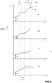
- Diagram 500 of the figure 9 schematically illustrates four recordings A, B, C, D of the neuromuscular Ac activity measured by the electronic organs 110, 111, 112 of the perineal probe 10 according to the invention, as a function of time T.
- Recording A corresponds to the data measured by a posterior force sensor of the electronic organ 112. The latter is placed at the level of the superficial plane of the perineum.
- the basic tone Tb of the endocavity and the superficial muscles of the perineum is measured. While the patient is about to make a movement leading to an increase in intra-abdominal pressure, an increase in neuromuscular activity can be seen on diagram 500, which corresponds to the perineal anticipation reflex Ra which activates the I fibers.
- the data measured following the anticipation reflex Ra correspond to the tone of the connective tissue Tjc increased by the increase in neuromuscular activity (I fiber).
- the tone of a functional connective tissue is remarkable by a plateau-shaped trace as illustrated for recording A.
- Recordings B and C of diagram 500 correspond respectively to the data measured by the EMG sensors of the electronic organs 110 of the flared portion 13. These recordings therefore correspond to the activity of the perineal muscles on either side of the PSM plane.
- On the tracing of recording C we note a hypertonicity of the basic tone Tb and a less marked curve profile than that of recording B.
- Such recordings can reveal a functional asymmetry of the perineal domes. This asymmetry can be found in pregnant women depending on the positioning of the baby's head. However, asymmetrical hypertonia can also be caused by obstetric, physical or psychological trauma.
- Recording D of diagram 500 corresponds to the data measured by the anterior force sensor of the electronic organ 112. The latter is placed at the level of the superficial plane of the perineum. On this recording, the dotted line corresponds to a degradation of the quality of the connective tissue of the perineum.
- the perineal probe 10 allows differentiated diagnoses of the different muscles that make up the superficial and deep planes of the perineum. In particular, it is possible to evaluate in a differentiated manner the functional state of the two paired bundles of iliococcygeal and ischiococcygeal muscles and/or pubovaginal and puborectal muscles (deep planes), of the bulbospongiosus muscles and of the ischiocavernosus muscles (superficial planes).
- the perineal probe 10 makes it possible to precisely establish the dysfunction: hypertonia or hypotonia of the basic tone and/or the tone of the connective tissue, dysfunction of the fast fibers and/or the slow fibers, absence or delay of the anticipation reflex, absence or delay of the myotatic reflex etc.
- the measured data can be interpreted directly or by comparison with a reference database.
- the perineal probe 10 allows a functional rehabilitation protocol to be carried out which can be targeted at the anatomical structures which present a disorder in their functional state.
- the therapist can apply electrostimulation programs adapted to treat the diagnosed dysfunction(s) through the EMG electrodes.
Landscapes
- Health & Medical Sciences (AREA)
- Life Sciences & Earth Sciences (AREA)
- Veterinary Medicine (AREA)
- Public Health (AREA)
- General Health & Medical Sciences (AREA)
- Animal Behavior & Ethology (AREA)
- Engineering & Computer Science (AREA)
- Biomedical Technology (AREA)
- Heart & Thoracic Surgery (AREA)
- Surgery (AREA)
- Pathology (AREA)
- Medical Informatics (AREA)
- Molecular Biology (AREA)
- Biophysics (AREA)
- Physics & Mathematics (AREA)
- Nuclear Medicine, Radiotherapy & Molecular Imaging (AREA)
- Radiology & Medical Imaging (AREA)
- Reproductive Health (AREA)
- Urology & Nephrology (AREA)
- Physical Education & Sports Medicine (AREA)
- Gynecology & Obstetrics (AREA)
- Cardiology (AREA)
- Oral & Maxillofacial Surgery (AREA)
- Gastroenterology & Hepatology (AREA)
- Surgical Instruments (AREA)
- Measuring And Recording Apparatus For Diagnosis (AREA)
- Measuring Leads Or Probes (AREA)
Claims (15)
- Perinealsonde (10), umfassend einen Sondenkörper, der Folgendes aufweist:- einen zylindrischen Abschnitt (12), der konfiguriert ist, um auf Ebene der Öffnung der vaginalen oder analen Endokavität eines Patienten positioniert zu werden,- einen aufgeweiteten Abschnitt (13), der sich von einem Ende (121) des zylindrischen Abschnitts (12) erstreckt, wobei sich der aufgeweitete Abschnitt (13) aufgeweitet von dem zylindrischen Abschnitt (12) zu einem freien Scheitelpunkt (130) erstreckt, wobei der aufgeweitete Abschnitt (13) zwischen einer gefalteten Position und einer entfalteten Position elastisch verformbar ist, um an den Wänden der Endokavität in Anlage zu kommen, und- elektronische Elemente (110, 111, 112), die konfiguriert sind, um mit Muskeln des Perineums eines Patienten zu interagieren, wobei die elektronischen Elemente (110, 111, 112) an dem aufgeweiteten Abschnitt (13) und/oder an dem zylindrischen Abschnitt (12) angeordnet sind,dadurch gekennzeichnet, dass der aufgeweitete Abschnitt (13) einerseits mindestens eine Seitenwand (132), die eine Innenfläche (1320) aufweist, die ein konisches Innenvolumen des aufgeweiteten Abschnitts (13) begrenzt, und andererseits mindestens eine Längsnut (135), die sich entlang einer Symmetrieebene der Perinealsonde (10) erstreckt, umfasst,
- Perinealsonde (10) nach Anspruch 1, wobei sich die Längsnut (135) entlang einer mittleren sagittalen Symmetrieebene (MSP) der Perinealsonde (10) erstreckt und die mindestens eine Seitenwand (132) in zwei Halbwände (1321, 1322) unterteilt.
- Perinealsonde (10) nach Anspruch 2, wobei der aufgeweitete Abschnitt (13) mindestens eine Nut (136, 137) aufweist, die sich quer in Bezug auf die mittlere Sagittalebene (MSP) der Perinealsonde (10) erstreckt, wobei sich die Nut (136, 137) an der Außenseite der Seitenwand (132) auf Ebene einer Basis (131) erstreckt, die an der Verbindung zwischen dem aufgeweiteten Abschnitt (13) und dem zylindrischen Abschnitt (12) angeordnet ist.
- Perinealsonde (10) nach einem der Ansprüche 1 bis 3, wobei der aufgeweitete Abschnitt (13) mindestens eine Öffnung (133, 134) aufweist, die entlang einer Symmetrieebene der Perinealsonde (10) angeordnet ist.
- Perinealsonde (10) nach Anspruch 4, wobei der aufgeweitete Abschnitt (13) Folgendes aufweist:- eine seitliche Öffnung (133), die entlang einer Symmetrieebene der Perinealsonde (10) angeordnet ist, und- eine Scheitelöffnung (134), die auf Ebene der freien Spitze (130) des aufgeweiteten Abschnitts (13) angeordnet ist.
- Perinealsonde (10) nach einem der Ansprüche 1 bis 5, die ein Halteelement (14a, 14b) aufweist, das zwischen einer entfalteten Position und einer gefalteten Position beweglich ist, wobei das Halteelement (14a, 14b) in der entfalteten Position ermöglicht, den aufgeweiteten Abschnitt (13) in der Endokavität des Patienten oder der Patientin in Position zu halten, und das Halteelement (14a, 14b) in der eingeklappten Position das Einführen der Perinealsonde (10) in die Endokavität ermöglicht.
- Perinealsonde (10) nach Anspruch 6, wobei das Halteelement (14a, 14b) eine Zunge (140) umfasst, die sich hervorstehend von dem aufgeweiteten Abschnitt (13) zu einem freien Ende (141) erstreckt, wobei die Zunge (140) entlang einer Symmetrieebene der Perinealsonde (10) hervorstehend ist.
- Perinealsonde (10) nach Anspruch 7, wobei die Zunge (140) an ihrem freien Ende (141) eine gerillte Oberfläche (145) aufweist.
- Perinealsonde (10) nach einem der Ansprüche 6 bis 8, wobei das Halteelement (14a, 14b) lösbar an dem zylindrischen Abschnitt (12) angebracht ist.
- Perinealsonde (10) nach einem der Ansprüche 7 bis 9, wobei die Zunge (140) in der entfalteten Position von dem aufgeweiteten Abschnitt (13) entlang einer anterior-posterioren Achse, die in der (PSM)-Ebene liegt, hervorsteht.
- Perinealsonde (10) nach einem der Ansprüche 1 bis 10, wobei sich der aufgeweitete Abschnitt (13) in einem Neigungswinkel α in Bezug auf eine Seitenwand (122) des zylindrischen Abschnitts (12) erstreckt, wobei der Neigungswinkel α zwischen 7°und 40° liegt.
- Perinealsonde (10) nach einem der Ansprüche 1 bis 11, wobei der aufgeweitete Abschnitt (13) zwei elektronische Elemente (110) umfasst, die auf beiden Seiten einer Symmetrieebene der Perinealsonde (10) angeordnet sind.
- Perinealsonde (10) nach einem der Ansprüche 1 bis 12, wobei der zylindrische Abschnitt (12) zwei elektronische Elemente (111, 112) umfasst, die auf beiden Seiten einer Symmetrieebene der Perinealsonde (10) angeordnet sind.
- Perinealsonde (10) nach den Ansprüchen 10 und 13, wobei der zylindrische Abschnitt (12) und der aufgeweitete Abschnitt (13) jeweils elektronische Elemente (110, 111) aufweisen, die aus EMG-Elektroden bestehen, wobei die elektronischen Elemente (110, 111) auf beiden Seiten einer mittleren Sagittalebene PSM der Perinealsonde (10) angeordnet sind.
- Perinealsonde nach einem der Ansprüche 1 bis 14, wobei die elektronischen Elemente (112) zwei Kraftsensoren umfassen, wobei die elektronischen Elemente (112) anterior-posterior auf beiden Seiten einer transversalen Mittelebene PTM der Perinealsonde (10) angeordnet sind.
Applications Claiming Priority (2)
| Application Number | Priority Date | Filing Date | Title |
|---|---|---|---|
| FR2110352A FR3127386B1 (fr) | 2021-09-30 | 2021-09-30 | Sonde périnéale |
| PCT/EP2022/077232 WO2023052567A1 (fr) | 2021-09-30 | 2022-09-29 | Sonde périnéale |
Publications (3)
| Publication Number | Publication Date |
|---|---|
| EP4408288A1 EP4408288A1 (de) | 2024-08-07 |
| EP4408288B1 true EP4408288B1 (de) | 2025-02-12 |
| EP4408288C0 EP4408288C0 (de) | 2025-02-12 |
Family
ID=79170812
Family Applications (1)
| Application Number | Title | Priority Date | Filing Date |
|---|---|---|---|
| EP22798272.5A Active EP4408288B1 (de) | 2021-09-30 | 2022-09-29 | Dammsonde |
Country Status (7)
| Country | Link |
|---|---|
| US (1) | US20240407727A1 (de) |
| EP (1) | EP4408288B1 (de) |
| CN (1) | CN118234432B (de) |
| ES (1) | ES3025608T3 (de) |
| FR (1) | FR3127386B1 (de) |
| PL (1) | PL4408288T3 (de) |
| WO (1) | WO2023052567A1 (de) |
Family Cites Families (11)
| Publication number | Priority date | Publication date | Assignee | Title |
|---|---|---|---|---|
| FR2827520B1 (fr) * | 2001-07-20 | 2004-04-02 | Dias Andre Mamberti | Sonde pince deformable vaginale ou anale a effet de ressort |
| FR2827779B1 (fr) * | 2001-07-27 | 2004-07-16 | Emc Thiers | Sonde de reeducation perineo-sphincterienne a deformation elastique |
| FR2930713A1 (fr) * | 2008-05-05 | 2009-11-06 | Pierre Lavoisier | Dispositif et procede de mesures des signaux physiologiques vaginaux et peri vaginaux et en particulier du debit sanguin et des muscles peri vaginaux |
| FR2941860B1 (fr) | 2009-02-06 | 2012-08-10 | Electronic Concept Lignon Innovation | Dispositif de reeducation et de mesure de la tension des muscles perineo-sphincteriens |
| US9492113B2 (en) * | 2011-07-15 | 2016-11-15 | Boston Scientific Scimed, Inc. | Systems and methods for monitoring organ activity |
| DK178782B1 (en) * | 2015-06-18 | 2017-01-23 | Fortis Pelvic Aps | Probe for measuring pelvic floor muscle parameters |
| EP3490686B1 (de) * | 2016-07-29 | 2023-11-15 | Axena Health, Inc. | Vorrichtungen und systeme zum trainieren der beckenbodenmuskeln |
| US20180055563A1 (en) * | 2016-08-24 | 2018-03-01 | Boston Scientific Scimed, Inc. | Solutions For Early Diagnoses, Prevention And Treatment Of Endometriosis |
| CN212522677U (zh) * | 2020-02-10 | 2021-02-12 | 西安西京医疗用品有限公司 | 一次性肛门引流装置 |
| CN213941862U (zh) * | 2020-11-13 | 2021-08-13 | 深圳市圆鲸科技有限公司 | 可视化电刺激阴道探头 |
| CN113274028A (zh) * | 2021-05-06 | 2021-08-20 | 江苏英诺麦德科技有限公司 | 一种子宫内膜蠕动波检测的设备和使用方法 |
-
2021
- 2021-09-30 FR FR2110352A patent/FR3127386B1/fr active Active
-
2022
- 2022-09-29 ES ES22798272T patent/ES3025608T3/es active Active
- 2022-09-29 CN CN202280065840.9A patent/CN118234432B/zh active Active
- 2022-09-29 EP EP22798272.5A patent/EP4408288B1/de active Active
- 2022-09-29 US US18/697,109 patent/US20240407727A1/en active Pending
- 2022-09-29 PL PL22798272.5T patent/PL4408288T3/pl unknown
- 2022-09-29 WO PCT/EP2022/077232 patent/WO2023052567A1/fr not_active Ceased
Also Published As
| Publication number | Publication date |
|---|---|
| PL4408288T3 (pl) | 2025-11-24 |
| US20240407727A1 (en) | 2024-12-12 |
| CN118234432B (zh) | 2025-03-14 |
| FR3127386B1 (fr) | 2024-11-08 |
| WO2023052567A1 (fr) | 2023-04-06 |
| FR3127386A1 (fr) | 2023-03-31 |
| EP4408288A1 (de) | 2024-08-07 |
| EP4408288C0 (de) | 2025-02-12 |
| CN118234432A (zh) | 2024-06-21 |
| ES3025608T3 (en) | 2025-06-09 |
Similar Documents
| Publication | Publication Date | Title |
|---|---|---|
| EP3297525B1 (de) | Diagnostische sonde zur messung der verformung einer endokavität und des widerstands von mindestens einem dammmuskel | |
| EP2285278B1 (de) | Vorrichtung und verfahren zur messung vaginaler und perivaginaler physiologischer signale und im besonderen des blutflusses in der perivaginalen muskulatur | |
| US8165695B2 (en) | System and method for selectively stimulating different body parts | |
| US20130150749A1 (en) | Probe for diagnosis and treatment of muscle contraction dysfunction | |
| DK2376020T3 (en) | VAGINAL DEVICE | |
| US7647112B2 (en) | System and method for selectively stimulating different body parts | |
| JP5525043B2 (ja) | 腹圧性尿失禁の矯正 | |
| US8728013B2 (en) | Device and method for fitting a pessary | |
| US20040030360A1 (en) | Intravaginal device for electrically stimulating and/or for sensing electrical activity of muscles and or nerves defining and surrounding the intravaginal cavity | |
| US20080009914A1 (en) | Systems and Methods for Implanting Tissue Stimulation Electrodes in the Pelvic Region | |
| EP3322474B1 (de) | Sondenvorrichtung zur verwaltung von stressbedingter harninkontinenz | |
| US20230149661A1 (en) | Pessary system and method for pelvic floor ligament support | |
| CN104013483B (zh) | 一种用于减轻女性尿失禁的医疗器械装置 | |
| EP4408288B1 (de) | Dammsonde | |
| Deffieux et al. | Sacral reflexes and urinary incontinence in women: new concepts | |
| Seccia et al. | Restoration of fecal continence with chronic electrostimulation of gracilis muscle 17 years after a Pickrell's operation | |
| Whelan | Practical anatomy, examination, palpation and manual therapy | |
| IL154646A (en) | Intravaginal device for electrically stimulating and/or for sensing electrical activity of muscles and/or nerves defining and surrounding the intravaginal cavity |
Legal Events
| Date | Code | Title | Description |
|---|---|---|---|
| STAA | Information on the status of an ep patent application or granted ep patent |
Free format text: STATUS: UNKNOWN |
|
| STAA | Information on the status of an ep patent application or granted ep patent |
Free format text: STATUS: THE INTERNATIONAL PUBLICATION HAS BEEN MADE |
|
| PUAI | Public reference made under article 153(3) epc to a published international application that has entered the european phase |
Free format text: ORIGINAL CODE: 0009012 |
|
| STAA | Information on the status of an ep patent application or granted ep patent |
Free format text: STATUS: REQUEST FOR EXAMINATION WAS MADE |
|
| 17P | Request for examination filed |
Effective date: 20240429 |
|
| AK | Designated contracting states |
Kind code of ref document: A1 Designated state(s): AL AT BE BG CH CY CZ DE DK EE ES FI FR GB GR HR HU IE IS IT LI LT LU LV MC MK MT NL NO PL PT RO RS SE SI SK SM TR |
|
| GRAP | Despatch of communication of intention to grant a patent |
Free format text: ORIGINAL CODE: EPIDOSNIGR1 |
|
| STAA | Information on the status of an ep patent application or granted ep patent |
Free format text: STATUS: GRANT OF PATENT IS INTENDED |
|
| DAV | Request for validation of the european patent (deleted) | ||
| DAX | Request for extension of the european patent (deleted) | ||
| INTG | Intention to grant announced |
Effective date: 20240903 |
|
| GRAS | Grant fee paid |
Free format text: ORIGINAL CODE: EPIDOSNIGR3 |
|
| GRAA | (expected) grant |
Free format text: ORIGINAL CODE: 0009210 |
|
| STAA | Information on the status of an ep patent application or granted ep patent |
Free format text: STATUS: THE PATENT HAS BEEN GRANTED |
|
| AK | Designated contracting states |
Kind code of ref document: B1 Designated state(s): AL AT BE BG CH CY CZ DE DK EE ES FI FR GB GR HR HU IE IS IT LI LT LU LV MC MK MT NL NO PL PT RO RS SE SI SK SM TR |
|
| REG | Reference to a national code |
Ref country code: GB Ref legal event code: FG4D Free format text: NOT ENGLISH |
|
| REG | Reference to a national code |
Ref country code: CH Ref legal event code: EP |
|
| REG | Reference to a national code |
Ref country code: DE Ref legal event code: R096 Ref document number: 602022010616 Country of ref document: DE |
|
| REG | Reference to a national code |
Ref country code: IE Ref legal event code: FG4D Free format text: LANGUAGE OF EP DOCUMENT: FRENCH |
|
| U01 | Request for unitary effect filed |
Effective date: 20250304 |
|
| U07 | Unitary effect registered |
Designated state(s): AT BE BG DE DK EE FI FR IT LT LU LV MT NL PT RO SE SI Effective date: 20250403 |
|
| REG | Reference to a national code |
Ref country code: ES Ref legal event code: FG2A Ref document number: 3025608 Country of ref document: ES Kind code of ref document: T3 Effective date: 20250609 |
|
| PG25 | Lapsed in a contracting state [announced via postgrant information from national office to epo] |
Ref country code: RS Free format text: LAPSE BECAUSE OF FAILURE TO SUBMIT A TRANSLATION OF THE DESCRIPTION OR TO PAY THE FEE WITHIN THE PRESCRIBED TIME-LIMIT Effective date: 20250512 |
|
| PG25 | Lapsed in a contracting state [announced via postgrant information from national office to epo] |
Ref country code: IS Free format text: LAPSE BECAUSE OF FAILURE TO SUBMIT A TRANSLATION OF THE DESCRIPTION OR TO PAY THE FEE WITHIN THE PRESCRIBED TIME-LIMIT Effective date: 20250612 Ref country code: NO Free format text: LAPSE BECAUSE OF FAILURE TO SUBMIT A TRANSLATION OF THE DESCRIPTION OR TO PAY THE FEE WITHIN THE PRESCRIBED TIME-LIMIT Effective date: 20250512 |
|
| PG25 | Lapsed in a contracting state [announced via postgrant information from national office to epo] |
Ref country code: HR Free format text: LAPSE BECAUSE OF FAILURE TO SUBMIT A TRANSLATION OF THE DESCRIPTION OR TO PAY THE FEE WITHIN THE PRESCRIBED TIME-LIMIT Effective date: 20250212 |
|
| PG25 | Lapsed in a contracting state [announced via postgrant information from national office to epo] |
Ref country code: GR Free format text: LAPSE BECAUSE OF FAILURE TO SUBMIT A TRANSLATION OF THE DESCRIPTION OR TO PAY THE FEE WITHIN THE PRESCRIBED TIME-LIMIT Effective date: 20250513 |
|
| REG | Reference to a national code |
Ref country code: CH Ref legal event code: U11 Free format text: ST27 STATUS EVENT CODE: U-0-0-U10-U11 (AS PROVIDED BY THE NATIONAL OFFICE) Effective date: 20251001 |
|
| PG25 | Lapsed in a contracting state [announced via postgrant information from national office to epo] |
Ref country code: SM Free format text: LAPSE BECAUSE OF FAILURE TO SUBMIT A TRANSLATION OF THE DESCRIPTION OR TO PAY THE FEE WITHIN THE PRESCRIBED TIME-LIMIT Effective date: 20250212 |
|
| PG25 | Lapsed in a contracting state [announced via postgrant information from national office to epo] |
Ref country code: CZ Free format text: LAPSE BECAUSE OF FAILURE TO SUBMIT A TRANSLATION OF THE DESCRIPTION OR TO PAY THE FEE WITHIN THE PRESCRIBED TIME-LIMIT Effective date: 20250212 |
|
| PG25 | Lapsed in a contracting state [announced via postgrant information from national office to epo] |
Ref country code: SK Free format text: LAPSE BECAUSE OF FAILURE TO SUBMIT A TRANSLATION OF THE DESCRIPTION OR TO PAY THE FEE WITHIN THE PRESCRIBED TIME-LIMIT Effective date: 20250212 |
|
| U20 | Renewal fee for the european patent with unitary effect paid |
Year of fee payment: 4 Effective date: 20250924 |
|
| PLBE | No opposition filed within time limit |
Free format text: ORIGINAL CODE: 0009261 |
|
| STAA | Information on the status of an ep patent application or granted ep patent |
Free format text: STATUS: NO OPPOSITION FILED WITHIN TIME LIMIT |
|
| PGFP | Annual fee paid to national office [announced via postgrant information from national office to epo] |
Ref country code: CH Payment date: 20251001 Year of fee payment: 4 |
|
| 26N | No opposition filed |
Effective date: 20251113 |
|
| PGFP | Annual fee paid to national office [announced via postgrant information from national office to epo] |
Ref country code: PL Payment date: 20250922 Year of fee payment: 4 |
|
| PGFP | Annual fee paid to national office [announced via postgrant information from national office to epo] |
Ref country code: ES Payment date: 20251030 Year of fee payment: 4 |