EP4408097A1 - Übertragungsverarbeitungsverfahren und -vorrichtung, endgerät, netzwerkseitige vorrichtung und speichermedium - Google Patents
Übertragungsverarbeitungsverfahren und -vorrichtung, endgerät, netzwerkseitige vorrichtung und speichermedium Download PDFInfo
- Publication number
- EP4408097A1 EP4408097A1 EP22872001.7A EP22872001A EP4408097A1 EP 4408097 A1 EP4408097 A1 EP 4408097A1 EP 22872001 A EP22872001 A EP 22872001A EP 4408097 A1 EP4408097 A1 EP 4408097A1
- Authority
- EP
- European Patent Office
- Prior art keywords
- tci state
- target
- csi
- tci
- resource set
- Prior art date
- Legal status (The legal status is an assumption and is not a legal conclusion. Google has not performed a legal analysis and makes no representation as to the accuracy of the status listed.)
- Pending
Links
Images


Classifications
-
- H—ELECTRICITY
- H04—ELECTRIC COMMUNICATION TECHNIQUE
- H04W—WIRELESS COMMUNICATION NETWORKS
- H04W52/00—Power management, e.g. Transmission Power Control [TPC] or power classes
- H04W52/04—Transmission power control [TPC]
- H04W52/18—TPC being performed according to specific parameters
- H04W52/24—TPC being performed according to specific parameters using SIR [Signal to Interference Ratio] or other wireless path parameters
- H04W52/242—TPC being performed according to specific parameters using SIR [Signal to Interference Ratio] or other wireless path parameters taking into account path loss
-
- H—ELECTRICITY
- H04—ELECTRIC COMMUNICATION TECHNIQUE
- H04B—TRANSMISSION
- H04B17/00—Monitoring; Testing
- H04B17/30—Monitoring; Testing of propagation channels
- H04B17/309—Measuring or estimating channel quality parameters
- H04B17/347—Path loss
-
- H—ELECTRICITY
- H04—ELECTRIC COMMUNICATION TECHNIQUE
- H04B—TRANSMISSION
- H04B7/00—Radio transmission systems, i.e. using radiation field
- H04B7/02—Diversity systems; Multi-antenna system, i.e. transmission or reception using multiple antennas
- H04B7/04—Diversity systems; Multi-antenna system, i.e. transmission or reception using multiple antennas using two or more spaced independent antennas
- H04B7/06—Diversity systems; Multi-antenna system, i.e. transmission or reception using multiple antennas using two or more spaced independent antennas at the transmitting station
- H04B7/0686—Hybrid systems, i.e. switching and simultaneous transmission
- H04B7/0695—Hybrid systems, i.e. switching and simultaneous transmission using beam selection
- H04B7/06952—Selecting one or more beams from a plurality of beams, e.g. beam training, management or sweeping
- H04B7/06966—Selecting one or more beams from a plurality of beams, e.g. beam training, management or sweeping using beam correspondence; using channel reciprocity, e.g. downlink beam training based on uplink sounding reference signal [SRS]
-
- H—ELECTRICITY
- H04—ELECTRIC COMMUNICATION TECHNIQUE
- H04L—TRANSMISSION OF DIGITAL INFORMATION, e.g. TELEGRAPHIC COMMUNICATION
- H04L5/00—Arrangements affording multiple use of the transmission path
-
- H—ELECTRICITY
- H04—ELECTRIC COMMUNICATION TECHNIQUE
- H04L—TRANSMISSION OF DIGITAL INFORMATION, e.g. TELEGRAPHIC COMMUNICATION
- H04L5/00—Arrangements affording multiple use of the transmission path
- H04L5/0001—Arrangements for dividing the transmission path
- H04L5/0003—Two-dimensional division
- H04L5/0005—Time-frequency
- H04L5/0007—Time-frequency the frequencies being orthogonal, e.g. OFDM(A) or DMT
- H04L5/001—Time-frequency the frequencies being orthogonal, e.g. OFDM(A) or DMT the frequencies being arranged in component carriers
-
- H—ELECTRICITY
- H04—ELECTRIC COMMUNICATION TECHNIQUE
- H04L—TRANSMISSION OF DIGITAL INFORMATION, e.g. TELEGRAPHIC COMMUNICATION
- H04L5/00—Arrangements affording multiple use of the transmission path
- H04L5/003—Arrangements for allocating sub-channels of the transmission path
- H04L5/0044—Allocation of payload; Allocation of data channels, e.g. PDSCH or PUSCH
-
- H—ELECTRICITY
- H04—ELECTRIC COMMUNICATION TECHNIQUE
- H04L—TRANSMISSION OF DIGITAL INFORMATION, e.g. TELEGRAPHIC COMMUNICATION
- H04L5/00—Arrangements affording multiple use of the transmission path
- H04L5/003—Arrangements for allocating sub-channels of the transmission path
- H04L5/0048—Allocation of pilot signals, i.e. of signals known to the receiver
- H04L5/005—Allocation of pilot signals, i.e. of signals known to the receiver of common pilots, i.e. pilots destined for multiple users or terminals
-
- H—ELECTRICITY
- H04—ELECTRIC COMMUNICATION TECHNIQUE
- H04L—TRANSMISSION OF DIGITAL INFORMATION, e.g. TELEGRAPHIC COMMUNICATION
- H04L5/00—Arrangements affording multiple use of the transmission path
- H04L5/003—Arrangements for allocating sub-channels of the transmission path
- H04L5/0048—Allocation of pilot signals, i.e. of signals known to the receiver
- H04L5/0051—Allocation of pilot signals, i.e. of signals known to the receiver of dedicated pilots, i.e. pilots destined for a single user or terminal
-
- H—ELECTRICITY
- H04—ELECTRIC COMMUNICATION TECHNIQUE
- H04L—TRANSMISSION OF DIGITAL INFORMATION, e.g. TELEGRAPHIC COMMUNICATION
- H04L5/00—Arrangements affording multiple use of the transmission path
- H04L5/003—Arrangements for allocating sub-channels of the transmission path
- H04L5/0053—Allocation of signalling, i.e. of overhead other than pilot signals
-
- H—ELECTRICITY
- H04—ELECTRIC COMMUNICATION TECHNIQUE
- H04L—TRANSMISSION OF DIGITAL INFORMATION, e.g. TELEGRAPHIC COMMUNICATION
- H04L5/00—Arrangements affording multiple use of the transmission path
- H04L5/0091—Signalling for the administration of the divided path, e.g. signalling of configuration information
- H04L5/0094—Indication of how sub-channels of the path are allocated
-
- H—ELECTRICITY
- H04—ELECTRIC COMMUNICATION TECHNIQUE
- H04L—TRANSMISSION OF DIGITAL INFORMATION, e.g. TELEGRAPHIC COMMUNICATION
- H04L69/00—Network arrangements, protocols or services independent of the application payload and not provided for in the other groups of this subclass
- H04L69/28—Timers or timing mechanisms used in protocols
-
- H—ELECTRICITY
- H04—ELECTRIC COMMUNICATION TECHNIQUE
- H04W—WIRELESS COMMUNICATION NETWORKS
- H04W52/00—Power management, e.g. Transmission Power Control [TPC] or power classes
- H04W52/04—Transmission power control [TPC]
- H04W52/06—TPC algorithms
- H04W52/14—Separate analysis of uplink or downlink
- H04W52/146—Uplink power control
-
- H—ELECTRICITY
- H04—ELECTRIC COMMUNICATION TECHNIQUE
- H04W—WIRELESS COMMUNICATION NETWORKS
- H04W52/00—Power management, e.g. Transmission Power Control [TPC] or power classes
- H04W52/04—Transmission power control [TPC]
- H04W52/30—Transmission power control [TPC] using constraints in the total amount of available transmission power
- H04W52/32—TPC of broadcast or control channels
- H04W52/325—Power control of control or pilot channels
-
- H—ELECTRICITY
- H04—ELECTRIC COMMUNICATION TECHNIQUE
- H04W—WIRELESS COMMUNICATION NETWORKS
- H04W72/00—Local resource management
- H04W72/04—Wireless resource allocation
-
- H—ELECTRICITY
- H04—ELECTRIC COMMUNICATION TECHNIQUE
- H04W—WIRELESS COMMUNICATION NETWORKS
- H04W72/00—Local resource management
- H04W72/12—Wireless traffic scheduling
-
- H—ELECTRICITY
- H04—ELECTRIC COMMUNICATION TECHNIQUE
- H04W—WIRELESS COMMUNICATION NETWORKS
- H04W72/00—Local resource management
- H04W72/20—Control channels or signalling for resource management
- H04W72/21—Control channels or signalling for resource management in the uplink direction of a wireless link, i.e. towards the network
-
- H—ELECTRICITY
- H04—ELECTRIC COMMUNICATION TECHNIQUE
- H04W—WIRELESS COMMUNICATION NETWORKS
- H04W72/00—Local resource management
- H04W72/20—Control channels or signalling for resource management
- H04W72/23—Control channels or signalling for resource management in the downlink direction of a wireless link, i.e. towards a terminal
-
- H—ELECTRICITY
- H04—ELECTRIC COMMUNICATION TECHNIQUE
- H04L—TRANSMISSION OF DIGITAL INFORMATION, e.g. TELEGRAPHIC COMMUNICATION
- H04L27/00—Modulated-carrier systems
- H04L27/26—Systems using multi-frequency codes
- H04L27/2601—Multicarrier modulation systems
- H04L27/2602—Signal structure
- H04L27/26025—Numerology, i.e. varying one or more of symbol duration, subcarrier spacing, Fourier transform size, sampling rate or down-clocking
Definitions
- This application pertains to the field of communications technologies, and specifically relates to a transmission processing method and apparatus, a terminal, a network-side device, and a storage medium.
- a plurality of channels or signals may use a same beam, and such beam may be referred to as a common beam (common beam).
- a network-side device indicates a common beam
- how to determine beam information for each reference signal for example, channel state information reference signal (Channel State Information Reference Signal, CSI-RS) and/or sounding reference signal (Sounding Reference Signal, SRS)
- CSI-RS Channel State Information Reference Signal
- SRS Sounding Reference Signal
- Embodiments of this application provide a transmission processing method and apparatus, a terminal, a network-side device, and a storage medium, so as to resolve the problem of how to determine beam information for each reference signal when a network-side device indicates a common beam.
- a transmission processing method including:
- a transmission processing method including:
- a transmission processing apparatus including:
- a transmission processing apparatus including:
- a terminal includes a processor, a memory, and a program or instructions stored in the memory and capable of running on the processor, and when the program or the instructions are executed by the processor, the steps of the method according to the first aspect are implemented.
- a terminal including a processor and a communication interface, where
- a network-side device includes a processor, a memory, and a program or instructions stored in the memory and capable of running on the processor, and when the program or the instructions are executed by the processor, the steps of the method according to the second aspect are implemented.
- a network-side device including a processor and a communication interface, where
- a readable storage medium where a program or instructions are stored in the readable storage medium, and when the program or the instructions are executed by a processor, the steps of the method according to the first aspect are implemented, or the steps of the method according to the second aspect are implemented.
- an embodiment of this application provides a chip, where the chip includes a processor and a communication interface, the communication interface is coupled to the processor, and the processor is configured to run a program or instructions to implement the steps of the method according to the first aspect or implement the steps of the method according to the second aspect.
- a computer program/program product is provided, where the computer program/program product is stored in a non-transitory storage medium, and the computer program/program product is executed by at least one processor to implement the method according to the first aspect or the method according to the second aspect.
- a communication device configured to execute the method according to the first aspect or execute the method according to the second aspect.
- the target information is obtained by the terminal; and the terminal determines, based on the target information, whether a target object uses a target transmission configuration indicator state TCI state; where the target information is specified by the protocol or indicated by the network-side device, the target object is at least one of a channel state information reference signal CSI-RS and a sounding reference signal SRS, and the target TCI state includes at least one of the following: a TCI state for a terminal-dedicated physical downlink shared channel PDSCH and for all or part of dedicated control resource sets; and a TCI state for a dynamic-grant or configured-grant based physical uplink shared channel PUSCH and for all dedicated physical uplink control channels PUCCHs.
- TCI state includes at least one of the following: a TCI state for a terminal-dedicated physical downlink shared channel PDSCH and for all or part of dedicated control resource sets; and a TCI state for a dynamic-grant or configured-grant based physical uplink shared channel PUSCH and for all dedicated physical uplink
- the terminal can determine, based on the target information, whether the CSI-RS and/or the SRS uses the target TCI state, and then may determine beam information for the CSI-RS and/or the SRS, so as to ensure that the terminal and the network-side device have consistent understanding on a beam during transmission of the CSI-RS and/or the SRS to guarantee beam alignment.
- first and second are intended to distinguish between similar objects but do not necessarily indicate a specific order or sequence. It should be understood that the data used in this way is interchangeable in appropriate circumstances so that the embodiments of this application can be implemented in other orders than the order illustrated or described herein, and “first” and “second” are usually for distinguishing same-type objects but not limiting the number of objects, for example, there may be one or more first objects.
- first and second are usually for distinguishing same-type objects but not limiting the number of objects, for example, there may be one or more first objects.
- “and/or” in this specification and claims indicates at least one of connected objects, and the symbol “/" generally indicates that the associated objects are in an "or” relationship.
- LTE Long Term Evolution
- LTE-A LTE-Advanced
- SC-FDMA single-carrier Frequency-Division Multiple Access
- system and “network” in the embodiments of this application are usually used interchangeably. Techniques described herein may be used in the aforementioned systems and radio technologies, and may also be used in other systems and radio technologies.
- New Radio New Radio
- NR New Radio
- NR terms are used in most of the following descriptions, although these technologies may also be applied to other applications than an NR system application, for example, the 6th generation (6 th Generation, 6G) mobile communications system.
- FIG. 1 is a block diagram of a wireless communication system to which the embodiments of this application are applicable.
- the wireless communication system includes a terminal 11 and a network-side device 12.
- the terminal 11 may be a terminal-side device, such as a mobile phone, a tablet computer (Tablet Personal Computer), a laptop computer (Laptop Computer) or a notebook computer, a personal digital assistant (Personal Digital Assistant, PDA), a palmtop computer, a netbook, an ultra-mobile personal computer (ultra-mobile personal computer, UMPC), a mobile Internet device (Mobile Internet Device, MID), an augmented reality (Augmented Reality, AR)/virtual reality (Virtual Reality, VR) device, a robot, a wearable device (Wearable Device), vehicle user equipment (Vehicle User Equipment, VUE), pedestrian user equipment (Pedestrian User Equipment, PUE), and a smart home device (a home device with wireless communication function, such as refrigerator, TV, washing machine, or furniture).
- a terminal-side device
- the wearable device includes: a smart watch, a wrist band, smart earphones, smart glasses, smart jewelry (smart bracelet, smart wristband, smart ring, smart necklace, smart anklet, smart ankle bracelet, or the like), smart wristband, smart clothing, game console, and the like. It should be noted that a specific type of the terminal 11 is not limited in the embodiments of this application.
- the network-side device 12 may be a base station or a core network device.
- the base station may be referred to as a NodeB, an evolved NodeB, an access point, a base transceiver station (Base Transceiver Station, BTS), a radio base station, a radio transceiver, a basic service set (Basic Service Set, BSS), an extended service set (Extended Service Set, ESS), a NodeB, an evolved NodeB (Evolved Node B, eNB), a home NodeB, a home evolved NodeB, a wireless local area network (Wireless Local Area Network, WLAN) access point, a wireless fidelity (Wireless Fidelity, WiFi) node, a transmission and reception point (Transmitting Receiving Point, TRP), or another appropriate term in the art.
- the base station is not limited to a specific technical term. It should be noted that in the embodiments of this application, the base station in the NR system is merely used as an example, and a specific type of the base station is not limited.
- Beam indication (beam indication) mechanism
- the network-side device may perform beam indication for downlink and uplink channels or reference signals, so as to establish beam links between the network-side device and the UE, thereby implementing channel or reference signal transmission.
- the beam indication mechanism for CSI-RS is as follows:
- the network-side device configures beam information for the CSI-RS by using RRC signaling, and triggers the CSI-RS by using downlink control information (Downlink Control Information, DCI).
- DCI Downlink Control Information
- the beam information described in this application may also be referred to as: spatial relation (spatial relation) information, spatial domain transmission filter (spatial domain transmission filter) information, spatial domain reception filter (spatial domain reception filter) information, spatial filter (spatial filter) information, transmission configuration indicator state (Transmission Configuration Indicator state, TCI state) information, quasi co-location (Quasi co-location, QCL) information, QCL parameter, or the like.
- spatial relation spatial relation
- spatial domain transmission filter spatial domain transmission filter
- spatial domain reception filter spatial domain reception filter
- spatial filter spatial filter
- transmission configuration indicator state Transmission Configuration Indicator state
- TCI state Transmission Configuration Indicator state
- QCL quasi co-location
- QCL quasi co-location
- the default beam mechanism for aperiodic CSI-RSs is defined as follows: If a scheduling offset between the last symbol of a physical downlink control channel (Physical downlink control channel, PDCCH) carrying triggered DCI and the first symbol of an aperiodic CSI-RS resource in a non-zero power (Non-Zero Power, NZP) CSI reference signal (Reference Signal, RS) (NZP-CSI-RS) resource set (the NZP-CSI-RS resource set is not configured with a higher layer parameter trs-Info (trs-Info is a parameter for a tracking refernece signal (Tracking Refernece Signal, TRS) message))) is less than a UE-reported threshold BeamSwitchTiming, when a reported value is one of the values ⁇ 14,28,48 ⁇ and enableBeamSwitchTiming (enableBeamSwitchTiming is a parameter for enabling beam switching timing) is not
- the first behavior includes: If any other downlink (Downlink, DL) signal using a TCI state indicated by the network-side device is present in a same symbol as the CSI-RS, the UE applies a QCL assumption of another DL signal to receive the aperiodic CSI-RS.
- the another DL signal refers to a physical downlink shared channel (Physical downlink shared channel, PDSCH) that is scheduled by a PDCCH.
- the PDCCH for scheduling the PDSCH is associated with a same coresetPoolIndex with a PDCCH for triggering the aperiodic CSI-RS, and a scheduling offset is greater than or equal to a threshold timeDurationForQCL (timeDurationForQCL).
- the another DL signal refers to another aperiodic CSI-RS, where a PDCCH for triggering the another aperiodic CSI-RS is associated with a same coresetPoolIndex as a PDCCH for triggering the CSI-RS; and a scheduling offset for the another aperiodic CSI-RS is greater than or equal to the UE-reported threshold beamSwitchTiming (beamSwitchTiming), where the UE reports one of the values ⁇ 14,28,48 ⁇ and enableBeamSwitchTiming is not configured.
- beamSwitchTiming UE-reported threshold beamSwitchTiming
- the another DL signal refers to another aperiodic CSI-RS, where a PDCCH for triggering the another aperiodic CSI-RS is associated with a same coresetPoolIndex as a PDCCH for triggering the CSI-RS, and a scheduling offset for the another aperiodic CSI-RS is greater than or equal to 48, where the UE-reported beamSwitchTiming-r16 is one of values ⁇ 224,336 ⁇ and enableBeamSwitchTiming is configured.
- the another DL signal refers to a periodic CSI-RS or a semi-persistent CSI-RS.
- the UE receives the CSI-RS by applying a QCL parameter for a CORESET associated with a listening search space.
- the CORESET is a CORESET with a smallest control resource set identifier (controlResourceSetId) in a nearest slot in CORESETs configured with a same coresetPoolIndex value as the PDCCH for triggering the CSI-RS.
- controlResourceSetId control resource set identifier
- one or more CORESETs are associated with a same coresetPoolIndex value as the PDCCH for triggering the CSI-RS.
- a second behavior is performed in a case that condition 2 is satisfied or that condition 2 is satisfied and condition 1 is not satisfied; where condition 2 includes: if enableTwoDefaultTCI-States (enableTwoDefaultTCI-States is a parameter for enabling two default TCL States) is configured for the UE, and at least one TCI code point is mapped to two TCI states.
- the second behavior includes: If any other DL signal using a TCI state indicated by the network-side device is present in a same symbol as the CSI-RS, the UE applies a QCL assumption of another DL signal to receive the CSI-RS.
- the another DL signal refers to a PDSCH with a scheduling offset being greater than or equal to the threshold timeDurationForQCL.
- the another DL signal alternatively refers to another aperiodic CSI-RS, and a scheduling offset of the another aperiodic CSI-RS is greater than or equal to the UE-reported threshold beamSwitchTiming, where the UE reports one of the values ⁇ 14,28,48 ⁇ and enableBeamSwitchTiming is not configured.
- the another DL signal alternatively refers to another aperiodic CSI-RS, and a scheduling offset of the another aperiodic CSI-RS is greater than or equal to 48, where UE-reported beamSwitchTiming-r16 is one of the values ⁇ 224,336 ⁇ and enableBeamSwitchTiming is configured.
- the another DL signal alternatively refers to a periodic CSI-RS or a semi-persistent CSI-RS. If two TCI states are indicated for a PDSCH present in the same symbol as the CSI-RS, the UE applies the 1st TCI state of the two TCI states when receiving the aperiodic CSI-RS.
- the UE applies the 1st TCI state of two TCI states corresponding to the lowest TCI code point, where the lowest TCI code point is a lowest code point of all TCI code points corresponding to the two TCI states, and is applicable to PDSCHs within an active bandwidth part (BandWidth Part, BWP) of a cell in which the aperiodic CSI-RS is located.
- BWP active bandwidth part
- condition 3 includes: any other DL signal using the TCI state indicated by the network-side device is present in the same symbol as the CSI-RS.
- the third behavior includes: The UE applies a QCL assumption of the another DL signal to receive an aperiodic CSI-RS.
- the another DL signal refers to a PDSCH with a scheduling offset being greater than or equal to the threshold timeDurationForQCL.
- the another DL signal alternatively refers to a periodic CSI-RS or a semi-persistent CSI-RS.
- the another DL signal alternatively refers to another aperiodic CSI-RS, and a scheduling offset of the another aperiodic CSI-RS is greater than or equal to the UE-reported threshold beamSwitchTiming, where the UE reports one of the values ⁇ 14,28,48 ⁇ and enableBeamSwitchTiming is not configured.
- the another DL signal alternatively refers to another aperiodic CSI-RS, and a scheduling offset of the another aperiodic CSI-RS is greater than or equal to the UE-reported threshold beamSwitchTiming, where a higher layer parameter trs-Info is configured for the NZP-CSI-RS resource set.
- the another DL signal alternatively refers to another aperiodic CSI-RS, and a scheduling offset of the another aperiodic CSI-RS is greater than or equal to 48, where the UE has reported beamSwitchTiming-r16, enableBeamSwitchTiming is configured, and a higher layer parameter repetition configured for the NZP-CSI-RS resource set is set to "off" or the higher layer parameters repetition and trs-info are not configured.
- the another DL signal alternatively refers to another aperiodic CSI-RS, and a scheduling offset of the another aperiodic CSI-RS is greater than or equal to the UE-reported threshold beamSwitchTiming-r16, where enableBeamSwitchTiming is configured, and the higher layer parameter repetition configured for the NZP-CSI-RS resource set is set to "on".
- condition 4 includes: the network-side device configures at least one CORESET for a BWP in which the aperiodic CSI-RS is located.
- the fourth behavior includes: the UE receives the CSI-RS by applying a QCL parameter for a CORESET associated with a listening search space, where the CORESET is a CORESET that has a smallest controlResourceSetId in the nearest slot, and one or more CORESETs monitored by the UE are present in an active BWP of the serving cell in the nearest slot.
- enableDefaultBeamForCCS is a parameter for enabling a default beam for common channel signaling (Common Channel Signaling, CCS)
- CCS Common Channel Signaling
- Power control parameters p0 and alpha for the SRS can be determined based on the p0 and alpha parameters configured by the network-side device for each SRS resource set, and the network-side device can also update or reassign the parameters via RRC.
- pathlossReferenceRS pathloss reference signal
- the network-side device can configure a pathloss (Path Loss, PL) reference signal list (pathlossRefereceRSList) in the SRS resource set, that is, configuring a plurality of pathloss RSs, and also determines one pathloss RS from the plurality of pathloss RSs via a MAC CE, for determining a pathloss of the SRS resource set.
- a pathloss Path Loss, PL reference signal list
- pathlossRefereceRSList pathloss reference signal list in the SRS resource set, that is, configuring a plurality of pathloss RSs, and also determines one pathloss RS from the plurality of pathloss RSs via a MAC CE, for determining a pathloss of the SRS resource set.
- the pathloss RS may be selected or updated via a MAC CE.
- the TCI state includes a joint (joint) TCI state and a separate (separate) TCI state, where the former uses a same TCI state for a plurality of downlink and uplink channels, and the latter includes a separate downlink (separate Downlink, separate DL) TCI state used for a plurality of downlink channels and a separate uplink (separate Uplink, separate UL) TCI state used for a plurality of uplink channels.
- the DL TCI state may be used for a terminal-dedicated (UE-dedicated) PDSCH and for part or all of the terminal-dedicated control resource set, or may be used for UE-dedicated reception on PDSCH and for UE-dedicated reception on part or all of the CORESETs.
- UE-dedicated terminal-dedicated
- the UL TCI state may be used for dynamic-grant or configured-grant based physical uplink shared channel (Physical Uplink Shared Channel, PUSCH) and all dedicated physical uplink control channel (Physical Uplink Control Channel, PUCCH) resources.
- Physical Uplink Shared Channel Physical Uplink Shared Channel
- PUCCH Physical Uplink Control Channel
- a demodulation reference signal (Demodulation Reference Signal, DMRS) associated with a control resource set and non-terminal-dedicated reception on an associated PDSCH can use a TCI state indicated by the network-side device for a terminal-dedicated PDSCH and part or all of the terminal-dedicated control resource sets.
- DMRS Demodulation Reference Signal
- channels/signals other than non-terminal-dedicated channels or signals can use the TCI state indicated by the network-side device for the terminal-dedicated PDSCH and part or all of the terminal-dedicated control resource sets.
- Both an aperiodic CSI-RS for CSI and an aperiodic CSI-RS for beam management can use the TCI state indicated by the network-side device for the terminal-dedicated PDSCH and part or all of the terminal-dedicated control resource sets.
- An aperiodic SRS resource or resource set for BM and an SRS resource or resource set for codebook-based uplink transmission/non-codebook-based uplink transmission for antenna switching may use a TCI state indicated by the network-side device for a dynamic-grant or configured-grant based PUSCH and all dedicated PUCCH resources.
- terminal-dedicated channel in the embodiments of this application may also be referred to as terminal-dedicated signal, and the foregoing condition 1 can be understood as that: at least two different control resource set pool index values are configured for the terminal and that a default beam is enabled for each of the control resource set pool indexes (the higher-layer parameter enableDefaultTCI-StatePerCoresetPoolIndex is configured).
- the foregoing condition 2 can be understood as that: a mode of enabling at least two default beams is configured for the terminal and at least one TCI code point corresponds to at least two TCI states during activation of the TCI state (the higher-layer parameter enableTwoDefaultTCI-States is configured).
- FIG. 2 is a flowchart of a transmission processing method according to an embodiment of this application. As shown in FIG. 2 , the method includes the following steps.
- Step 201 A terminal obtains target information.
- Step 202 The terminal determines, based on the target information, whether a target object uses a target transmission configuration indicator state TCI state.
- the target information is specified by a protocol or indicated by a network-side device, the target object is at least one of a channel state information reference signal CSI-RS and a sounding reference signal SRS, and the target TCI state includes at least one of the following:
- the target TCI state may be understood as a TCI state for indicating a common beam. Based on the target information, the terminal may determine whether the target object uses the target TCI state. If the target TCI state is used, it indicates that the common beam is used, and if the target TCI state is not used, it indicates that the common beam is not used. In this case, another preconfigured beam, or another beam indicated by the network, or a default beam may be used.
- the CSI-RS may include only an aperiodic CSI-RS
- the SRS may include only an aperiodic SRS.
- the target TCI state may be understood to be a separate DL TCI state when the target TCI state is a TCI state for a terminal-dedicated PDSCH and for all or part of dedicated control resource sets; or the target TCI state may be understood as a separate UL TCI state when the target TCI state is a TCI state for a dynamic-grant or configured-grant based PUSCH and for all dedicated physical uplink control channels PUCCHs.
- the target TCI state may be understood as a joint TCI state when the target TCI state is used for the terminal-dedicated PDSCH and for all or part of dedicated control resource sets, and is also used for the dynamic-grant or configured-grant based PUSCH and for all dedicated PUCCHs.
- default beam information for the CSI-RS and/or SRS indicated by the network-side device may be used when it is determined based on the target information to use the common beam for the CSI-RS and/or SRS.
- the target information is obtained by the terminal; and the terminal determines, based on the target information, whether a target object uses a target transmission configuration indicator state TCI state; where the target information is specified by the protocol or indicated by the network-side device, the target object is at least one of a channel state information reference signal CSI-RS and a sounding reference signal SRS, and the target TCI state includes at least one of the following: a TCI state for a terminal-dedicated physical downlink shared channel PDSCH and for all or part of dedicated control resource sets; and a TCI state for a dynamic-grant or configured-grant based physical uplink shared channel PUSCH and for all dedicated physical uplink control channels PUCCHs.
- TCI state includes at least one of the following: a TCI state for a terminal-dedicated physical downlink shared channel PDSCH and for all or part of dedicated control resource sets; and a TCI state for a dynamic-grant or configured-grant based physical uplink shared channel PUSCH and for all dedicated physical uplink
- the terminal can determine, based on the target information, whether the CSI-RS and/or the SRS uses the target TCI state, and then may determine beam information for the CSI-RS and/or the SRS, so as to ensure that the terminal and the network-side device have consistent understanding on a beam during transmission of the CSI-RS and/or the SRS to guarantee beam alignment.
- the target information satisfies at least one of the following:
- the target information is carried in any one of the following configuration information:
- the target information when the target information is in CSI-RS resource configuration (resource config), or configuration information for a CSI-RS resource set or CSI-RS resource, it may be used to indicate whether the CSI-RS uses the target TCI state; and when the target information is in configuration information for an SRS resource set or SRS resource, it may be used to indicate whether the SRS uses the target TCI state.
- the target information corresponds to SRS resource sets of different usages (usages)
- usages usages
- a TCI state for the first CSI-RS is a first TCI state, a second TCI state, a third TCI state, or a fourth TCI state.
- the target condition includes: a time domain offset between a first PDCCH triggering the first CSI-RS and the first CSI-RS is less than a first preset value.
- the target condition may further include other conditions in addition to the foregoing condition, for example, it may also include the following condition:
- the first preset value is a UE-reported threshold beam switch timing, where the reported value is one of the values ⁇ 14,28,48 ⁇ and enableBeamSwitchTiming is not configured, or a first preset value is 48, where the UE reports beamSwitchTiming-r16, enableBeamSwitchTiming is configured, and a higher layer parameter repetition configured for the NZP-CSI-RS resource set is set to "off" or the higher layer parameters repetition is not configured, or the first preset value is a UE-reported threshold beamSwitchTiming-r16, where enableBeamSwitchTiming is configured and the higher layer parameter repetition configured for the NZP-CSI-RS resource set is set to "on".
- the TCI state for the first CSI-RS may use a first TCI state, a second TCI state, a third TCI state, or a fourth TCI state; or if the time domain offset between the first CSI-RS and the first PDCCH triggering the first CSI-RS is greater than or equal to the first preset value, it is determined, based on the target information, whether the first CSI-RS uses the target TCI state.
- the first TCI state satisfies at least one of the following:
- the first TCI state may be the target TCI state or may be another TCI state different from the target TCI state.
- the second PDCCH for scheduling or triggering the first downlink signal is carried in a non-terminal-dedicated control resource set, or the second PDCCH is carried in a common search space (Common Search Space, CSS).
- a common search space Common Search Space, CSS
- scheduling or triggering the first downlink signal may be understood as scheduling the first PDSCH or triggering the second CSI-RS.
- the first downlink signal is a first PDSCH or is an aperiodic second CSI-RS.
- the second CSI-RS may be a periodic CSI-RS, an aperiodic CSI-RS, or a semi-persistent CSI-RS.
- the first TCI state is the N-th TCI state in the plurality of TCI states
- N is a second preset value
- the plurality of TCI states satisfy at least one of the following:
- the network-side device may indicate a plurality of TCI states for the terminal when the condition 5 is satisfied and none of conditions 1 to 4 is satisfied.
- the second TCI state is a TCI state for a periodic or semi-persistent second CSI-RS
- the TCI state of the second CSI-RS is a TCI state different from the target TCI state
- the second CSI-RS is transmitted in a same time unit as the first CSI-RS.
- the third TCI state is a TCI state for the first control resource set, and the first control resource set satisfies at least one of the following:
- the first control resource set may be a terminal-dedicated control resource set (which may also be referred to as that at least one of associated search spaces is a control resource set of a terminal-dedicated search space, or all of the associated search spaces are control resource sets of the terminal-dedicated search space), or may be a non-terminal-dedicated control resource set (which may also be referred to as that at least one of the associated search spaces is a control resource set of a non-terminal-dedicated search space, or all of the associated search spaces are control resource sets of the non-terminal-dedicated search space).
- the TCI state for the first control resource set varies in different cases, as described in more detail below.
- the TCI state for the first control resource set is the target TCI state.
- the third TCI state satisfies any one of the following:
- the third TCI state satisfies at least one of the following:
- the fourth TCI state satisfies at least one of the following:
- the fourth TCI state when the network-side device indicates one target TCI state, the fourth TCI state may be directly the target TCI state; or when the network-side device indicates a plurality of target TCI states, the fourth TCI state may be a preset TCI state in the plurality of target TCI states, for example, the N-th target TCI state.
- the fourth TCI state when there is one TCI state most recently indicated by the network-side device, the fourth TCI state may be directly the TCI state most recently indicated by the network-side device; and when there are a plurality of TCI states most recently indicated by the network-side device, the fourth TCI state may be a preset TCI state in the plurality of TCI states most recently indicated by the network-side device, for example, the N-th TCI state.
- the network-side device may first activate the TCI state via a MAC CE and then indicate the TCI state via DCI.
- the indicated or activated TCI state is a TCI state for an active (active) BWP of a cell in which the first CSI-RS is located.
- the fourth TCI state is a fifth TCI state in a case that the first CSI-RS satisfies any one of the following conditions:
- a scenario for using an activated TCI state may be determined based on the foregoing conditions.
- the plurality of TCI states satisfy at least one of the following:
- the plurality of TCI states may be that part or all of the TCI states correspond to different control resource set pool indexes, part or all of the TCI states correspond to different channel groups, or part or all of the TCI states correspond to different terminal panels.
- the TCI state for the first CSI-RS is determined according to a target rule, the target rule including at least one of the following:
- the first preset condition includes: at least two different control resource set pool index values are configured for the terminal and a default beam is started for each control resource set pool index.
- the second preset condition includes: a mode of enabling at least two default beams is configured for the terminal and at least one TCI code point corresponds to at least two TCI states during activation of the TCI state.
- the third preset condition includes: a first downlink signal transmitted in a same time unit as the first CSI-RS is present.
- the fourth preset condition includes any one of the following:
- the fifth preset condition includes: the network-side device configures a first parameter for the terminal, the first parameter being used to indicate starting a default beam used for cross-carrier scheduling.
- the preset rule satisfies at least one of the following:
- the first sub-condition includes at least one of the following:
- the first sub-condition further includes any one of the following:
- the second sub-condition includes: a first downlink signal transmitted in a same time unit as the first CSI-RS is a periodic or semi-persistent second CSI-RS.
- the third sub-condition includes: a first downlink signal transmitted in a same time unit as the first CSI-RS is absent.
- a power control parameter for the SRS satisfies at least one of the following:
- the candidate value may be configured by at least one of the following: BWP configuration information, SRS configuration information, SRS resource set configuration information, and SRS resource configuration information. It should be understood that in a case that the SRS does not use a common beam or does not use a target TCI state, the target power control parameter may be determined in accordance with existing related technologies.
- the method further includes: when the terminal is in a carrier aggregation scenario, receiving, by the terminal, configuration information from the network-side device, where the configuration information is used to configure target parameter information, and the target parameter information is used to indicate a validataion time of the target TCI state.
- the target parameter information may be understood as parameter information for a BAT, for which a time granularity may be defined as millisecond (ms), slot (slot), or symbol (symbol).
- ms millisecond
- slot slot
- symbol symbol
- Y milliseconds, Y slots or Y symbols may be included.
- the target parameter information is carried in any one of the following configuration information:
- the target parameter information includes at least one Y value, and the at least one Y value including any one of the following:
- the method further includes:
- the network-side device may indicate the target information by using RRC or MAC CE signaling.
- the first CSI-RS may include only an aperiodic CSI-RS
- the first SRS may include only an aperiodic SRS.
- the target information may be used to indicate that all CSI-RS and/or SRS resources use the common beam. For example, it is used when a value of one of the parameters is enable (enable), and it is not used when a value of one of the parameters is disable (disable) or default.
- the target information may be in the configuration information for the CSI-RS resource set or the CSI-RS resource, and is used for indicating whether the CSI-RS resource set or the CSI-RS resource uses the common beam.
- the target information may be in the configuration information for the SRS resource set or the SRS resource, and is used for indicating whether the SRS resource set or the SRS resource uses the common beam.
- the target information may be used to indicate whether SRS resource sets of different usages (usage) use the common beam.
- the beam information indicated by the network-side device for each CSI-RS resource and/or SRS resource may be default when the target information indicates that the CSI-RS and/or SRS uses the common beam.
- the common beam may be further understood as: a DL TCI state for a terminal-dedicated physical downlink shared channel PDSCH and for all or part of dedicated control resource sets (UE-dedicated reception on PDSCH and for UE-dedicated reception on all or subset of CORESETs), and/or an UL TCI state for a dynamic-grant or configured-grant based physical uplink shared channel PUSCH and for all dedicated physical uplink control channels PUCCHs (dynamic-grant/configured-grant based PUSCH and all of the dedicated PUCCH resources).
- a DL TCI state for a terminal-dedicated physical downlink shared channel PDSCH and for all or part of dedicated control resource sets (UE-dedicated reception on PDSCH and for UE-dedicated reception on all or subset of CORESETs)
- an UL TCI state for a dynamic-grant or configured-grant based physical uplink shared channel PUSCH and for all dedicated physical uplink control channels PUCCHs (dynamic
- the beam information for the aperiodic CSI-RS may be determined according to the following behavior:
- the second PDCCH for scheduling the PDSCH is on a non-UE-dedicated control resource set (non-UE-dedicated CORESET).
- the second PDCCH for triggering the second CSI-RS is associated with a same CORESETPoolIndex as the first PDCCH for triggering the first CSI-RS, and condition A is satisfied, then the TCI state used by the first CSI-RS satisfies at least one of the following:
- the second PDCCH for triggering the second CSI-RS is on a non-UE-dedicated CORESET.
- condition A includes any one of the following:
- the first CSI-RS uses a same TCI state as the second CSI-RS.
- the TCI state of the second CSI-RS is different from the R17 TCI state indicated by the network-side device for the UE-dedicated channel.
- the first CSI-RS uses the beam information for the first CORESET, and the first control resource set satisfies at least one of the following:
- both the first CSI-RS and the first CORESET use the same R17 TCI state indicated by the network-side device for the UE-dedicated channel.
- the first CSI-RS uses an R17 TCI state indicated by the network for the UE-dedicated channel, or the first CSI-RS uses a TCI state that is indicated by the network and that is different from that of the UE-dedicated channel.
- the first CSI-RS satisfies at least one of the following:
- a second operation behavior is performed; where the second preset condition includes: if enableTwoDefaultTCI-States is configured for the UE and at least one TCI code point is mapped to two TCI States.
- the second operation behavior includes:
- the second PDCCH for scheduling the PDSCH is on a non-UE-dedicated CORESET.
- the first CSI-RS uses a preset (for example, the 1st) TCI state in the plurality of TCI states; where the plurality of TCI states may correspond to different CORESETPoolIndexes, different channel groups, terminal panels, and the like.
- the TCI state used by the first CSI-RS satisfies at least one of the following:
- the second PDCCH for triggering the second CSI-RS is on a non-UE-dedicated CORESET.
- condition C includes any one of the following:
- the first CSI-RS uses a same TCI state as the second CSI-RS.
- the TCI state of the second CSI-RS is different from the R17 TCI state indicated by the network-side device for the UE-dedicated channel.
- the first CSI-RS satisfies at least one of the following:
- the plurality of TCI states may correspond to different CORESETPoolIndexes, different channel groups, terminal panels, and the like.
- the indicated or activated TCI state is in an active BWP of a cell in which the CSI-RS is located.
- the foregoing scenario of using the activated TCI state may be:
- a third operation behavior is performed; where the third preset condition includes: any other DL signal using the TCI state indicated by the network-side device is present in the same symbol as the CSI-RS.
- the third operation behavior includes:
- the TCI state used by the first CSI-RS satisfies at least one of the following:
- the second PDCCH for scheduling the PDSCH is on a non-UE-dedicated CORESET.
- the TCI state used by the first CSI-RS satisfies at least one of the following:
- the second PDCCH for triggering the second CSI-RS is on a non-UE-dedicated CORESET.
- condition D includes any one of the following:
- the first CSI-RS uses a same TCI state as the second CSI-RS.
- the TCI state of the second CSI-RS is different from the R17 TCI state indicated by the network-side device for the UE-dedicated channel.
- a fourth operation behavior is performed; where the fourth preset condition includes:
- the fourth operation behavior includes: using beam information of a first CORESET for the first CSI-RS, where the first control resource set satisfies at least one of the following:
- both the first CSI-RS and the first CORESET use the same R17 TCI state indicated by the network-side device for the UE-dedicated channel.
- the first CSI-RS uses an R17 TCI state indicated by the network for the UE-dedicated channel, or the first CSI-RS uses a TCI state that is indicated by the network and that is different from that of the UE-dedicated channel.
- the first CSI-RS satisfies at least one of the following:
- a fifth operation behavior is performed.
- the fifth preset condition includes: the network-side device configures a first parameter for the terminal, the first parameter being used to indicate starting a default beam used for cross-carrier scheduling.
- the fifth operation behavior includes: using at least one of the following beam information for the first CSI-RS:
- the plurality of TCI states may correspond to different CORESETPoolIndexes, different channel groups, terminal panels, and the like.
- the indicated or activated TCI state is in an active BWP of a cell in which the CSI-RS is located.
- the foregoing scenario of using the activated TCI state may be:
- the candidate value may be configured in at least one of BWP configuration information, SRS configuration information, SRS resource set configuration information, and SRS resource configuration information.
- the network-side device configures parameter information of a BAT (or beam validation time) for the common beam information.
- the parameter information of the BAT may be Y ms/slots/symbols.
- a group of Y values configured by the network-side device is in at least one of the following configuration information: band configuration information, configuration information of a group of CCs (CC list (CC list)), CC configuration information, BWP configuration information, and PUCCH configuration information.
- the group of Y values satisfies at least one of the following:
- the network-side device indicates a common TCI state ID, for determining common beam information for a group of CCs.
- the behavior of determining the BAT includes:
- configuration information for band1 includes: ⁇ SCS1, Y1 ⁇ SCS2, Y2 ⁇ SCS3, Y3 ⁇ .... Accordingly, the Y value corresponding to each SCS can be determined, or the Y value corresponding to the smallest SCS can be determined.
- configuration information for band1 includes: ⁇ SCS1, Y11, Y12 ⁇ SCS2, Y21, Y22 ⁇ SCS3, Y31, Y32 ⁇ ....
- the two Y values corresponding to each SCS correspond to two CCs on which the ACK may be configured, respectively, and the Y values can be found based on SCSs of BWPs of cells in which SCSs and ACKs are located.
- FIG. 3 is a flowchart of another transmission processing method according to an embodiment of this application. As shown in FIG. 3 , the method includes the following step.
- Step 301 A network-side device sends target information to a terminal; where the target information is used to indicate whether a target object uses a target transmission configuration indicator state TCI state.
- the target object is at least one of a channel state information reference signal CSI-RS and a sounding reference signal SRS, and the target TCI state includes at least one of the following:
- the target information satisfies at least one of the following:
- the target information is carried in any one of the following configuration information:
- a TCI state for the first CSI-RS is a first TCI state, a second TCI state, a third TCI state, or a fourth TCI state; where the target condition includes: a time domain offset between a first PDCCH triggering the first CSI-RS and the first CSI-RS is less than a first preset value.
- the first TCI state satisfies any one of the following:
- the second PDCCH for scheduling or triggering the first downlink signal is carried on a non-terminal-dedicated control resource set.
- the first downlink signal is a first PDSCH or is an aperiodic second CSI-RS.
- the first TCI state is the N-th TCI state in the plurality of TCI states
- N is a second preset value
- the plurality of TCI states satisfy at least one of the following:
- the second TCI state is a TCI state for a periodic or semi-persistent second CSI-RS
- the TCI state of the second CSI-RS is a TCI state different from the target TCI state
- the second CSI-RS is transmitted in a same time unit as the first CSI-RS.
- the third TCI state is a TCI state for a first control resource set, and the first control resource set satisfies at least one of the following:
- the TCI state for the first control resource set is the target TCI state.
- the third TCI state satisfies any one of the following:
- the third TCI state satisfies at least one of the following:
- the fourth TCI state satisfies at least one of the following:
- the fourth TCI state is a fifth TCI state in a case that the first CSI-RS satisfies any one of the following conditions:
- the plurality of TCI states satisfy at least one of the following:
- the TCI state for the first CSI-RS is determined according to a target rule, the target rule including at least one of the following:
- the first preset condition includes: at least two different control resource set pool index values are configured for the terminal and a default beam is started for each control resource set pool index.
- the second preset condition includes: a mode of enabling at least two default beams is configured for the terminal and at least one TCI code point corresponds to at least two TCI states during activation of the TCI state.
- the third preset condition includes: a first downlink signal transmitted in a same time unit as the first CSI-RS is present.
- the fourth preset condition includes any one of the following:
- the fifth preset condition includes: the network-side device configures a first parameter for the terminal, the first parameter being used to indicate starting a default beam used for cross-carrier scheduling.
- the preset rule satisfies at least one of the following:
- the first sub-condition includes at least one of the following:
- the first sub-condition further includes any one of the following:
- the second sub-condition includes: a first downlink signal transmitted in a same time unit as the first CSI-RS is a periodic or semi-persistent second CSI-RS.
- the third sub-condition includes: a first downlink signal transmitted in a same time unit as the first CSI-RS is absent.
- a power control parameter for the SRS satisfies at least one of the following:
- the candidate value is configured by at least one of the following: BWP configuration information, SRS configuration information, SRS resource set configuration information, and SRS resource configuration information.
- the method further includes: when the terminal is in a carrier aggregation scenario, sending configuration information to the terminal, where the configuration information is used to configure target parameter information, and the target parameter information is used to indicate a validataion time of the target TCI state.
- the target parameter information is carried in any one of the following configuration information:
- the target parameter information includes at least one Y value, and the at least one Y value including any one of the following:
- this embodiment is used as an implementation of the network-side device corresponding to the embodiment shown in FIG. 2 .
- the execution body may be a transmission processing apparatus, or a control module for executing the transmission processing method in the transmission processing apparatus.
- the transmission processing method being performed by the transmission processing apparatus is used as an example to describe the transmission processing apparatus provided in the embodiments of this application.
- FIG. 4 is a structural diagram of a transmission processing apparatus according to an embodiment of this applicattion. As shown in FIG. 4 , the transmission processsing apparatus 400 includes:
- the target information satisfies at least one of the following:
- the target information is carried in any one of the following configuration information:
- a TCI state for the first CSI-RS is a first TCI state, a second TCI state, a third TCI state, or a fourth TCI state; where the target condition includes: a time domain offset between a first PDCCH triggering the first CSI-RS and the first CSI-RS is less than a first preset value.
- the first TCI state satisfies any one of the following:
- the second PDCCH for scheduling or triggering the first downlink signal is carried on a non-terminal-dedicated control resource set.
- the first downlink signal is a first PDSCH or is an aperiodic second CSI-RS.
- the first TCI state is the N-th TCI state in the plurality of TCI states
- N is a second preset value
- the plurality of TCI states satisfy at least one of the following:
- the second TCI state is a TCI state for a periodic or semi-persistent second CSI-RS
- the TCI state of the second CSI-RS is a TCI state different from the target TCI state
- the second CSI-RS is transmitted in a same time unit as the first CSI-RS.
- the third TCI state is a TCI state for a first control resource set, and the first control resource set satisfies at least one of the following:
- the TCI state for the first control resource set is the target TCI state.
- the third TCI state satisfies any one of the following:
- the third TCI state satisfies at least one of the following:
- the fourth TCI state satisfies at least one of the following:
- the fourth TCI state is a fifth TCI state in a case that the first CSI-RS satisfies any one of the following conditions:
- the plurality of TCI states satisfy at least one of the following:
- the TCI state for the first CSI-RS is determined according to a target rule, the target rule including at least one of the following:
- the first preset condition includes: at least two different control resource set pool index values are configured for the terminal and a default beam is started for each control resource set pool index.
- the second preset condition includes: a mode of enabling at least two default beams is configured for the terminal and at least one TCI code point corresponds to at least two TCI states during activation of the TCI state.
- the third preset condition includes: a first downlink signal transmitted in a same time unit as the first CSI-RS is present.
- the fourth preset condition includes any one of the following:
- the fifth preset condition includes: the network-side device configures a first parameter for the terminal, the first parameter being used to indicate starting a default beam used for cross-carrier scheduling.
- the preset rule satisfies at least one of the following:
- the first sub-condition includes at least one of the following:
- the first sub-condition further includes any one of the following:
- the second sub-condition includes: a first downlink signal transmitted in a same time unit as the first CSI-RS is a periodic or semi-persistent second CSI-RS.
- the third sub-condition includes: a first downlink signal transmitted in a same time unit as the first CSI-RS is absent.
- a power control parameter for the SRS satisfies at least one of the following:
- the candidate value is configured by at least one of the following: BWP configuration information, SRS configuration information, SRS resource set configuration information, and SRS resource configuration information.
- the transmission processing apparatus 400 further includes: a receiving module, configured to: when the terminal is in a carrier aggregation scenario, receive configuration information from the network-side device, where the configuration information is used to configure target parameter information, and the target parameter information is used to indicate a validataion time of the target TCI state.
- a receiving module configured to: when the terminal is in a carrier aggregation scenario, receive configuration information from the network-side device, where the configuration information is used to configure target parameter information, and the target parameter information is used to indicate a validataion time of the target TCI state.
- the target parameter information is carried in any one of the following configuration information:
- the target parameter information includes at least one Y value, and the at least one Y value including any one of the following:
- the determining module is further configured to: determine a validation time for each BWP in each CC based on a second object; where the second object includes any one of the following:
- the transmission processing apparatus provided in this embodiment of this application is capable of implementing the processes that are implemented by the method embodiments in FIG. 2 . To avoid repetition, details are not described herein again.
- FIG. 5 is a structural diagram of a transmission processing apparatus according to an embodiment of this applicattion. As shown in FIG. 5 , the transmission processsing apparatus 500 includes:
- the target information satisfies at least one of the following:
- the target information is carried in any one of the following configuration information:
- a TCI state for the first CSI-RS is a first TCI state, a second TCI state, a third TCI state, or a fourth TCI state; where the target condition includes: a time domain offset between a first PDCCH triggering the first CSI-RS and the first CSI-RS is less than a first preset value.
- the first TCI state satisfies any one of the following:
- the second PDCCH for scheduling or triggering the first downlink signal is carried on a non-terminal-dedicated control resource set.
- the first downlink signal is a first PDSCH or is an aperiodic second CSI-RS.
- the first TCI state is the N-th TCI state in the plurality of TCI states
- N is a second preset value
- the plurality of TCI states satisfy at least one of the following:
- the second TCI state is a TCI state for a periodic or semi-persistent second CSI-RS
- the TCI state of the second CSI-RS is a TCI state different from the target TCI state
- the second CSI-RS is transmitted in a same time unit as the first CSI-RS.
- the third TCI state is a TCI state for a first control resource set, and the first control resource set satisfies at least one of the following:
- the TCI state for the first control resource set is the target TCI state.
- the third TCI state satisfies any one of the following:
- the third TCI state satisfies at least one of the following:
- the fourth TCI state satisfies at least one of the following:
- the fourth TCI state is a fifth TCI state in a case that the first CSI-RS satisfies any one of the following conditions:
- the plurality of TCI states satisfy at least one of the following:
- the TCI state for the first CSI-RS is determined according to a target rule, the target rule including at least one of the following:
- the first preset condition includes: at least two different control resource set pool index values are configured for the terminal and a default beam is started for each control resource set pool index.
- the second preset condition includes: a mode of enabling at least two default beams is configured for the terminal and at least one TCI code point corresponds to at least two TCI states during activation of the TCI state.
- the third preset condition includes: a first downlink signal transmitted in a same time unit as the first CSI-RS is present.
- the fourth preset condition includes any one of the following:
- the fifth preset condition includes: the network-side device configures a first parameter for the terminal, the first parameter being used to indicate starting a default beam used for cross-carrier scheduling.
- the preset rule satisfies at least one of the following:
- the first sub-condition includes at least one of the following:
- the first sub-condition further includes any one of the following:
- the second sub-condition includes: a first downlink signal transmitted in a same time unit as the first CSI-RS is a periodic or semi-persistent second CSI-RS.
- the third sub-condition includes: a first downlink signal transmitted in a same time unit as the first CSI-RS is absent.
- a power control parameter for the SRS satisfies at least one of the following:
- the candidate value is configured by at least one of the following: BWP configuration information, SRS configuration information, SRS resource set configuration information, and SRS resource configuration information.
- the sending module is further configured to: when the terminal is in a carrier aggregation scenario, send configuration information to the terminal, where the configuration information is used to configure target parameter information, and the target parameter information is used to indicate a validataion time of the target TCI state.
- the target parameter information is carried in any one of the following configuration information:
- the target parameter information includes at least one Y value, and the at least one Y value including any one of the following:
- the transmission processing apparatus provided in this embodiment of this application is capable of implementing the processes that are implemented by the method embodiments in FIG. 3 . To avoid repetition, details are not described herein again.
- the transmission processing apparatus in this embodiment of this application may be an apparatus, or an apparatus or electric device having an operating system, or may be a component, an integrated circuit, or a chip in the terminal.
- the apparatus may be a mobile terminal or a non-mobile terminal.
- the mobile terminal may include but is not limited to the types of the terminal 11 listed above, and the non-mobile terminal may be a server, a network attached storage (Network Attached Storage, NAS), a personal computer (Personal computer, PC), a television (Television, TV), a teller machine, a self-service machine, or the like, which is not specifically limited in this embodiment of this application.
- Network Attached Storage NAS
- PC Personal computer
- TV Television
- teller machine teller machine
- self-service machine or the like, which is not specifically limited in this embodiment of this application.
- the transmission processing apparatus provided in this embodiment of this application can implement the processes implemented in the method embodiment in FIG. 2 and FIG. 3 , with the same technical effects achieved. To avoid repetition, details are not described herein again.
- an embodiment of this application further provides a communication device 600, including a processor 601, a memory 602, and a program or instructions stored in the memory 602 and capable of running on the processor 601.
- a communication device 600 including a processor 601, a memory 602, and a program or instructions stored in the memory 602 and capable of running on the processor 601.
- the communication device 600 is a terminal and when the program or instructions are executed by the processor 601, the processes of the foregoing embodiment of the transmission processing method are implemented, with the same technical effects achieved.
- the communication device 600 is a network-side device and when the program or instructions are executed by the processor 601, the processes of the foregoing embodiment of the transmission processing method are implemented, with the same technical effects achieved. To avoid repetition, details are not described herein again.
- An embodiment of this application further provides a terminal including a processor and a communication interface, and the processor is configured to obtain target information, and determine, based on the target information, whether a target object uses a target transmission configuration indicator state TCI state; where the target information is specified by a protocol or indicated by a network-side device, the target object is at least one of a channel state information reference signal CSI-RS and a sounding reference signal SRS, and the target TCI state includes at least one of the following:
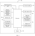
- FIG. 7 is a schematic diagram of a hardware structure of a terminal for implementing the embodiments of this application.
- the terminal 700 includes but is not limited to at least part of components such as a radio frequency unit 701, a network module 702, an audio output unit 703, an input unit 704, a sensor 705, a display unit 706, a user input unit 707, an interface unit 708, a memory 709, and a processor 710.
- the terminal 700 may further include a power supply (for example, a battery) supplying power to the components, and the power supply may be logically connected to the processor 710 through a power management system. In this way, functions such as charge management, discharge management, and power consumption management are implemented by using the power management system.
- a power supply for example, a battery
- functions such as charge management, discharge management, and power consumption management are implemented by using the power management system.
- the structure of the terminal shown in FIG. 7 does not constitute any limitation on the terminal.
- the terminal may include more or fewer components than shown in the figure, or a combination of some components, or the components disposed differently. Details are not described herein again.
- the input unit 704 may include a graphics processing unit (Graphics Processing Unit, GPU) and a microphone.
- the graphics processing unit processes image data of a still picture or video obtained by an image capture apparatus (such as a camera) in a video capture mode or an image capture mode.
- the display unit 706 may include a display panel, and the display panel may be configured in a form of a liquid crystal display, an organic light-emitting diode, and the like.
- the user input unit 707 may include a touch panel and other input devices.
- the touch panel is also referred to as a touchscreen.
- the touch panel may include two parts: a touch detection apparatus and a touch controller.
- the other input devices may include but are not limited to a physical keyboard, a function key (such as a volume control key or a power on/off key), a trackball, a mouse, a joystick, and the like. Details are not described herein.
- the radio frequency unit 701 receives downlink data from a network-side device, and then sends the downlink data to the processor 710 for processing; and also sends uplink data to the network-side device.
- the radio frequency unit 701 includes but is not limited to an antenna, at least one amplifier, a transceiver, a coupler, a low noise amplifier, a duplexer, and the like.
- the memory 709 may be configured to store software programs or instructions and various data.
- the memory 109 may include a program or instruction storage area and a data storage area.
- the program or instruction storage area may store an operating system, an application program or instruction required by at least one function (for example, a sound playback function or an image playback function), and the like.
- the memory 709 may include a high-speed random access memory, and may further include a non-volatile memory.
- the non-volatile memory may be a read-only memory (Read-Only memory, ROM), a programmable read-only memory (Programmable ROM, PROM), an erasable programmable read-only memory (Erasable PROM, EPROM), an electrically erasable programmable read-only memory (Electrically EPROM, EEPROM), or a flash memory, for example, at least one disk storage device, a flash memory device, or another non-transitory solid-state storage device.
- ROM Read-Only memory
- PROM programmable read-only memory
- Erasable PROM Erasable PROM
- EPROM electrically erasable programmable read-only memory
- EEPROM electrically erasable programmable read-only memory
- flash memory for example, at least one disk storage device, a flash memory device, or another non-transitory solid-state storage device.
- the processor 710 may include one or more processing units.
- an application processor and a modem processor may be integrated in the processor 710.
- the application processor primarily processes an operating system, user interfaces, application programs or instructions, and the like.
- the modem processor primarily processes radio communication, for example, being a baseband processor. It can be understood that the modem processor may alternatively be not integrated in the processor 710.
- the processor 710 is configured to obtain target information, and determine, based on the target information, whether a target object uses a target transmission configuration indicator state TCI state; where the target information is specified by a protocol or indicated by a network-side device, the target object is at least one of a channel state information reference signal CSI-RS and a sounding reference signal SRS, and the target TCI state includes at least one of the following:
- the processor 710 in this embodiment of this application can implement the steps of the foregoing transmission processing method, with the same effects achieved.
- An embodiment of this application further provides a network-side device including a processor and a communication interface, and the processor is configured to send target information to a terminal; where the target information is used to indicate whether a target obj ect uses a target transmission configuration indicator state TCI state; where the target object is at least one of a channel state information reference signal CSI-RS and a sounding reference signal SRS, and the target TCI state includes at least one of the following:
- the network-side device embodiments correspond to the foregoing network-side device method embodiments, and the implementation processes and implementations of the foregoing method embodiments can be applied to the network-side device embodiments, with the same technical effects achieved.
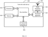
- the network-side device 800 includes an antenna 801, a radio frequency apparatus 802, and a baseband apparatus 803.
- the antenna 801 is connected to the radio frequency apparatus 802.
- the radio frequency apparatus 802 receives information by using the antenna 801, and sends the received information to the baseband apparatus 803 for processing.
- the baseband apparatus 803 processes to-be-sent information, and sends the information to the radio frequency apparatus 802; and the radio frequency apparatus 802 processes the received information and then sends the information out by using the antenna 801.
- the frequency band processing apparatus may be located in the baseband apparatus 803.
- the method performed by the network-side device in the foregoing embodiments may be implemented in the baseband apparatus 803, and the baseband apparatus 803 includes a processor 804 and a memory 805.
- the baseband apparatus 803 may include, for example, at least one baseband board, where a plurality of chips are disposed on the baseband board. As shown in FIG. 8 , one of the chips is, for example, the processor 804, connected to the memory 805, to invoke a program in the memory 805 to perform the operation of the network-side device shown in the foregoing method embodiment.
- the baseband apparatus 803 may further include a network interface 806, configured to exchange information with the radio frequency apparatus 802, where the interface is, for example, a common public radio interface (Common Public Radio Interface, CPRI).
- CPRI Common Public Radio Interface
- the network-side device in this embodiment of this application further includes: instructions or a program stored in the memory 805 and capable of running on the processor 804.
- the processor 804 invokes the instructions or program in the memory 805 to execute the method executed by the modules shown in FIG. 5 , with the same technical effects achieved. To avoid repetition, details are not repeated herein.
- An embodiment of this application further provides a readable storage medium, where a program or an instruction is stored in the readable storage medium.
- a program or an instruction is stored in the readable storage medium.
- the processor is a processor in the electronic device described in the foregoing embodiments.
- the readable storage medium includes a computer-readable storage medium, for example, a computer read-only memory (Read-Only Memory, ROM), a random access memory (Random Access Memory, RAM), a magnetic disk, or an optical disc.
- An embodiment of this application further provides a chip, where the chip includes a processor and a communication interface.
- the communication interface is coupled to the processor, and the processor is configured to run a program or instructions to implement the processes of the foregoing embodiments of the transmission processing method, with the same technical effects achieved. To avoid repetition, details are not described herein again.
- the chip mentioned in the embodiments of this application may also be referred to as a system-level chip, a system chip, a chip system, a system-on-chip, or the like.
- An embodiment of this application further provides a computer program product, where the computer program product is stored in a non-transitory storage medium, and when being executed by at least one processor, the computer program product is configured to implement the processes of the foregoing embodiments of the transmission processing method, with the same technical effects achieved. To avoid repetition, details are not repeated herein.
- An embodiment of this application further provides a communication device, configured to perform the processes of the foregoing embodiments of the transmission processing method, with the same technical effects achieved. To avoid repetition, details are not described herein.
- the computer software product is stored in a storage medium (such as a ROM/RAM, a magnetic disk, or an optical disc), and includes several instructions for instructing a terminal (which may be a mobile phone, a computer, a server, an air conditioner, a base station, or the like) to perform the methods described in the embodiments of this application.
- a storage medium such as a ROM/RAM, a magnetic disk, or an optical disc
- a terminal which may be a mobile phone, a computer, a server, an air conditioner, a base station, or the like
Landscapes
- Engineering & Computer Science (AREA)
- Signal Processing (AREA)
- Computer Networks & Wireless Communication (AREA)
- Physics & Mathematics (AREA)
- Mathematical Physics (AREA)
- Quality & Reliability (AREA)
- Electromagnetism (AREA)
- Computer Security & Cryptography (AREA)
- Mobile Radio Communication Systems (AREA)
Applications Claiming Priority (2)
| Application Number | Priority Date | Filing Date | Title |
|---|---|---|---|
| CN202111117407.9A CN115866107B (zh) | 2021-09-23 | 2021-09-23 | 传输处理方法、装置、终端、网络侧设备及存储介质 |
| PCT/CN2022/120140 WO2023045955A1 (zh) | 2021-09-23 | 2022-09-21 | 传输处理方法、装置、终端、网络侧设备及存储介质 |
Publications (2)
| Publication Number | Publication Date |
|---|---|
| EP4408097A1 true EP4408097A1 (de) | 2024-07-31 |
| EP4408097A4 EP4408097A4 (de) | 2024-12-18 |
Family
ID=85652417
Family Applications (1)
| Application Number | Title | Priority Date | Filing Date |
|---|---|---|---|
| EP22872001.7A Pending EP4408097A4 (de) | 2021-09-23 | 2022-09-21 | Übertragungsverarbeitungsverfahren und -vorrichtung, endgerät, netzwerkseitige vorrichtung und speichermedium |
Country Status (6)
| Country | Link |
|---|---|
| US (1) | US20240235761A1 (de) |
| EP (1) | EP4408097A4 (de) |
| JP (1) | JP7760046B2 (de) |
| KR (1) | KR20240058187A (de) |
| CN (1) | CN115866107B (de) |
| WO (1) | WO2023045955A1 (de) |
Families Citing this family (7)
| Publication number | Priority date | Publication date | Assignee | Title |
|---|---|---|---|---|
| US12219591B2 (en) * | 2021-05-11 | 2025-02-04 | Mediatek, Inc. | Method and user equipment for scheduling with multiple cells |
| US12464471B2 (en) * | 2022-03-01 | 2025-11-04 | Qualcomm Incorporated | Techniques for flexible configuration of power control parameters |
| US12484073B2 (en) | 2023-07-18 | 2025-11-25 | Shenzhen Transsion Holdings Co., Ltd. | Processing method, communication device and storage medium |
| CN116600402B (zh) * | 2023-07-18 | 2024-01-19 | 深圳传音控股股份有限公司 | 处理方法、通信设备及存储介质 |
| CN119966594A (zh) * | 2023-11-07 | 2025-05-09 | 维沃移动通信有限公司 | 一种全双工通信处理方法、装置、终端及网络侧设备 |
| WO2025007630A1 (zh) * | 2024-04-29 | 2025-01-09 | 深圳传音控股股份有限公司 | 处理方法、通信设备及存储介质 |
| CN118175642B (zh) * | 2024-05-16 | 2024-10-01 | 荣耀终端有限公司 | 一种通信方法、终端设备、通信装置及存储介质 |
Family Cites Families (7)
| Publication number | Priority date | Publication date | Assignee | Title |
|---|---|---|---|---|
| CN110719139B (zh) * | 2018-07-13 | 2020-08-18 | 维沃移动通信有限公司 | 搜索空间参数确定方法和终端设备 |
| EP3629492B1 (de) * | 2018-09-25 | 2026-01-07 | Ofinno, LLC | Strahlkonfiguration für sekundärzellen |
| JP7323605B2 (ja) * | 2019-04-26 | 2023-08-08 | 株式会社Nttドコモ | 端末、無線通信方法及びシステム |
| US10973044B1 (en) * | 2019-10-03 | 2021-04-06 | Qualcomm Incorporated | Default spatial relation for SRS/PUCCH |
| CN112689321B (zh) * | 2019-10-18 | 2022-08-05 | 维沃移动通信有限公司 | 一种功率控制参数确定方法及终端 |
| CN113259952B (zh) * | 2020-02-07 | 2022-07-15 | 维沃移动通信有限公司 | 波束指示方法、装置、设备及介质 |
| EP4301062A4 (de) * | 2021-02-25 | 2024-04-10 | Beijing Xiaomi Mobile Software Co., Ltd. | Strahlbestimmungsverfahren und -vorrichtung und kommunikationsvorrichtung |
-
2021
- 2021-09-23 CN CN202111117407.9A patent/CN115866107B/zh active Active
-
2022
- 2022-09-21 EP EP22872001.7A patent/EP4408097A4/de active Pending
- 2022-09-21 JP JP2024518226A patent/JP7760046B2/ja active Active
- 2022-09-21 WO PCT/CN2022/120140 patent/WO2023045955A1/zh not_active Ceased
- 2022-09-21 KR KR1020247012902A patent/KR20240058187A/ko active Pending
-
2024
- 2024-03-20 US US18/611,177 patent/US20240235761A1/en active Pending
Also Published As
| Publication number | Publication date |
|---|---|
| EP4408097A4 (de) | 2024-12-18 |
| JP2024533645A (ja) | 2024-09-12 |
| JP7760046B2 (ja) | 2025-10-24 |
| US20240235761A1 (en) | 2024-07-11 |
| WO2023045955A1 (zh) | 2023-03-30 |
| KR20240058187A (ko) | 2024-05-03 |
| CN115866107B (zh) | 2025-05-13 |
| CN115866107A (zh) | 2023-03-28 |
Similar Documents
| Publication | Publication Date | Title |
|---|---|---|
| EP4408097A1 (de) | Übertragungsverarbeitungsverfahren und -vorrichtung, endgerät, netzwerkseitige vorrichtung und speichermedium | |
| US20250071683A1 (en) | Monitoring method and apparatus, terminal, network-side device, and readable storage medium | |
| WO2023202632A1 (zh) | 资源分配方法、设备及可读存储介质 | |
| US20240364488A1 (en) | TCI State Updating Method and Communication Device | |
| US12538325B2 (en) | Transmission mode determining method and apparatus, and communications device | |
| US20240154773A1 (en) | Tci state determining method and apparatus, terminal, and network-side device | |
| US20240405949A1 (en) | Method and apparatus for determining downlink tci state, terminal, and network side device | |
| US20250055652A1 (en) | Beam information determination method, and terminal, and network-side device | |
| US20240357664A1 (en) | Communication operation execution method and apparatus, terminal, and storage medium | |
| EP4383816A1 (de) | Messrelaxationsverfahren und -vorrichtung, endgerät und netzwerkseitige vorrichtung | |
| WO2024022247A1 (zh) | 定时提前ta的维护方法、装置、设备及介质 | |
| CN116633506B (zh) | 信息激活方法、终端及网络侧设备 | |
| EP4668808A1 (de) | Informationsmeldeverfahren und -vorrichtung sowie endgerät | |
| US20240178900A1 (en) | Method and Apparatus for Determining Beam Application Time, Terminal, and Network-Side Device | |
| EP4543084A1 (de) | Übergabeverarbeitungsverfahren und -vorrichtung sowie kommunikationsvorrichtung | |
| EP4661545A1 (de) | Dci-grössenbestimmungsverfahren, dci-sendeverfahren, vorrichtung und zugehörige vorrichtung | |
| US20240405956A1 (en) | Uplink tci state determining method and apparatus, terminal, and network-side device | |
| US20250015965A1 (en) | Beam Information Indication Method, Terminal and Network Side Device | |
| US20240179674A1 (en) | Method and apparatus for determining low mobility state, terminal, and network-side device | |
| EP4383626A1 (de) | Verfahren und vorrichtung zur bestimmung von strahlinformationen sowie kommunikationsvorrichtung und speichermedium | |
| JP2026505812A (ja) | Bwp決定方法、伝送方法、装置、端末及びネットワーク側機器 | |
| CN116633508A (zh) | 下行tci状态确定方法、装置、终端和网络侧设备 | |
| CN120076022A (zh) | 资源激活方法、装置、终端及网络侧设备 |
Legal Events
| Date | Code | Title | Description |
|---|---|---|---|
| STAA | Information on the status of an ep patent application or granted ep patent |
Free format text: STATUS: THE INTERNATIONAL PUBLICATION HAS BEEN MADE |
|
| PUAI | Public reference made under article 153(3) epc to a published international application that has entered the european phase |
Free format text: ORIGINAL CODE: 0009012 |
|
| STAA | Information on the status of an ep patent application or granted ep patent |
Free format text: STATUS: REQUEST FOR EXAMINATION WAS MADE |
|
| 17P | Request for examination filed |
Effective date: 20240415 |
|
| AK | Designated contracting states |
Kind code of ref document: A1 Designated state(s): AL AT BE BG CH CY CZ DE DK EE ES FI FR GB GR HR HU IE IS IT LI LT LU LV MC MK MT NL NO PL PT RO RS SE SI SK SM TR |
|
| A4 | Supplementary search report drawn up and despatched |
Effective date: 20241118 |
|
| RIC1 | Information provided on ipc code assigned before grant |
Ipc: H04W 72/23 20230101ALI20241112BHEP Ipc: H04W 72/21 20230101ALI20241112BHEP Ipc: H04W 72/12 20230101ALI20241112BHEP Ipc: H04W 52/32 20090101ALI20241112BHEP Ipc: H04W 52/24 20090101ALI20241112BHEP Ipc: H04W 52/14 20090101ALI20241112BHEP Ipc: H04L 69/28 20220101ALI20241112BHEP Ipc: H04L 5/00 20060101ALI20241112BHEP Ipc: H04B 7/06 20060101ALI20241112BHEP Ipc: H04W 72/04 20230101AFI20241112BHEP |
|
| DAV | Request for validation of the european patent (deleted) | ||
| DAX | Request for extension of the european patent (deleted) |