EP4408094A1 - Srs-sendeverfahren und -vorrichtung zur antennenschaltkonfiguration und speichermedium - Google Patents
Srs-sendeverfahren und -vorrichtung zur antennenschaltkonfiguration und speichermedium Download PDFInfo
- Publication number
- EP4408094A1 EP4408094A1 EP21957820.0A EP21957820A EP4408094A1 EP 4408094 A1 EP4408094 A1 EP 4408094A1 EP 21957820 A EP21957820 A EP 21957820A EP 4408094 A1 EP4408094 A1 EP 4408094A1
- Authority
- EP
- European Patent Office
- Prior art keywords
- srs
- srs resource
- type
- resource
- antenna switching
- Prior art date
- Legal status (The legal status is an assumption and is not a legal conclusion. Google has not performed a legal analysis and makes no representation as to the accuracy of the status listed.)
- Withdrawn
Links
Images




Classifications
-
- H—ELECTRICITY
- H04—ELECTRIC COMMUNICATION TECHNIQUE
- H04W—WIRELESS COMMUNICATION NETWORKS
- H04W72/00—Local resource management
- H04W72/04—Wireless resource allocation
-
- H—ELECTRICITY
- H04—ELECTRIC COMMUNICATION TECHNIQUE
- H04B—TRANSMISSION
- H04B7/00—Radio transmission systems, i.e. using radiation field
- H04B7/02—Diversity systems; Multi-antenna system, i.e. transmission or reception using multiple antennas
- H04B7/04—Diversity systems; Multi-antenna system, i.e. transmission or reception using multiple antennas using two or more spaced independent antennas
- H04B7/06—Diversity systems; Multi-antenna system, i.e. transmission or reception using multiple antennas using two or more spaced independent antennas at the transmitting station
- H04B7/0602—Diversity systems; Multi-antenna system, i.e. transmission or reception using multiple antennas using two or more spaced independent antennas at the transmitting station using antenna switching
-
- H—ELECTRICITY
- H04—ELECTRIC COMMUNICATION TECHNIQUE
- H04B—TRANSMISSION
- H04B7/00—Radio transmission systems, i.e. using radiation field
- H04B7/02—Diversity systems; Multi-antenna system, i.e. transmission or reception using multiple antennas
- H04B7/04—Diversity systems; Multi-antenna system, i.e. transmission or reception using multiple antennas using two or more spaced independent antennas
- H04B7/0404—Diversity systems; Multi-antenna system, i.e. transmission or reception using multiple antennas using two or more spaced independent antennas the mobile station comprising multiple antennas, e.g. to provide uplink diversity
-
- H—ELECTRICITY
- H04—ELECTRIC COMMUNICATION TECHNIQUE
- H04B—TRANSMISSION
- H04B7/00—Radio transmission systems, i.e. using radiation field
- H04B7/02—Diversity systems; Multi-antenna system, i.e. transmission or reception using multiple antennas
- H04B7/04—Diversity systems; Multi-antenna system, i.e. transmission or reception using multiple antennas using two or more spaced independent antennas
- H04B7/06—Diversity systems; Multi-antenna system, i.e. transmission or reception using multiple antennas using two or more spaced independent antennas at the transmitting station
- H04B7/0602—Diversity systems; Multi-antenna system, i.e. transmission or reception using multiple antennas using two or more spaced independent antennas at the transmitting station using antenna switching
- H04B7/0604—Diversity systems; Multi-antenna system, i.e. transmission or reception using multiple antennas using two or more spaced independent antennas at the transmitting station using antenna switching with predefined switching scheme
-
- H—ELECTRICITY
- H04—ELECTRIC COMMUNICATION TECHNIQUE
- H04B—TRANSMISSION
- H04B7/00—Radio transmission systems, i.e. using radiation field
- H04B7/02—Diversity systems; Multi-antenna system, i.e. transmission or reception using multiple antennas
- H04B7/04—Diversity systems; Multi-antenna system, i.e. transmission or reception using multiple antennas using two or more spaced independent antennas
- H04B7/06—Diversity systems; Multi-antenna system, i.e. transmission or reception using multiple antennas using two or more spaced independent antennas at the transmitting station
- H04B7/0686—Hybrid systems, i.e. switching and simultaneous transmission
- H04B7/0691—Hybrid systems, i.e. switching and simultaneous transmission using subgroups of transmit antennas
-
- H—ELECTRICITY
- H04—ELECTRIC COMMUNICATION TECHNIQUE
- H04B—TRANSMISSION
- H04B7/00—Radio transmission systems, i.e. using radiation field
- H04B7/02—Diversity systems; Multi-antenna system, i.e. transmission or reception using multiple antennas
- H04B7/04—Diversity systems; Multi-antenna system, i.e. transmission or reception using multiple antennas using two or more spaced independent antennas
- H04B7/08—Diversity systems; Multi-antenna system, i.e. transmission or reception using multiple antennas using two or more spaced independent antennas at the receiving station
- H04B7/0802—Diversity systems; Multi-antenna system, i.e. transmission or reception using multiple antennas using two or more spaced independent antennas at the receiving station using antenna selection
- H04B7/0805—Diversity systems; Multi-antenna system, i.e. transmission or reception using multiple antennas using two or more spaced independent antennas at the receiving station using antenna selection with single receiver and antenna switching
-
- H—ELECTRICITY
- H04—ELECTRIC COMMUNICATION TECHNIQUE
- H04L—TRANSMISSION OF DIGITAL INFORMATION, e.g. TELEGRAPHIC COMMUNICATION
- H04L5/00—Arrangements affording multiple use of the transmission path
- H04L5/003—Arrangements for allocating sub-channels of the transmission path
- H04L5/0048—Allocation of pilot signals, i.e. of signals known to the receiver
- H04L5/0051—Allocation of pilot signals, i.e. of signals known to the receiver of dedicated pilots, i.e. pilots destined for a single user or terminal
-
- H—ELECTRICITY
- H04—ELECTRIC COMMUNICATION TECHNIQUE
- H04L—TRANSMISSION OF DIGITAL INFORMATION, e.g. TELEGRAPHIC COMMUNICATION
- H04L5/00—Arrangements affording multiple use of the transmission path
- H04L5/0091—Signalling for the administration of the divided path, e.g. signalling of configuration information
- H04L5/0094—Indication of how sub-channels of the path are allocated
-
- H—ELECTRICITY
- H04—ELECTRIC COMMUNICATION TECHNIQUE
- H04W—WIRELESS COMMUNICATION NETWORKS
- H04W28/00—Network traffic management; Network resource management
- H04W28/16—Central resource management; Negotiation of resources or communication parameters, e.g. negotiating bandwidth or QoS [Quality of Service]
- H04W28/18—Negotiating wireless communication parameters
-
- H—ELECTRICITY
- H04—ELECTRIC COMMUNICATION TECHNIQUE
- H04L—TRANSMISSION OF DIGITAL INFORMATION, e.g. TELEGRAPHIC COMMUNICATION
- H04L5/00—Arrangements affording multiple use of the transmission path
- H04L5/0001—Arrangements for dividing the transmission path
- H04L5/0014—Three-dimensional division
- H04L5/0023—Time-frequency-space
Definitions
- This disclosure relates to the field of communication technologies, and in particular to a method and an apparatus for sending SRS used for antenna switching configuration as well as a storage medium.
- SRS sounding reference signal
- the SRS resources corresponding to different antenna switching configurations may be aperiodic SRS (A-SRS), semi-persistent SRS (SP-SRS), or periodic SRS (P-SRS).
- A-SRS aperiodic SRS
- SP-SRS semi-persistent SRS
- P-SRS periodic SRS
- the SRS resources may not be updated synchronously.
- the terminal may still have P/SP-SRS or A-SRS/P-SRS in the previous antenna switching configuration.
- the SRS resources cannot be updated synchronously, it may result in that a switch of the transmit link or the receive link (Tx/Rx RF chain) cannot be actually turned off, thereby failing to completely solve power-saving needs and the like of terminals.
- this disclosure provides a method and an apparatus for sending SRS used for antenna switching configuration as well as a storage medium.
- a method for sending SRS used for antenna switching configuration which is applied to a terminal and includes: determining an SRS type configured by the terminal for antenna switching configuration, where the SRS type includes at least two different SRS types; determining that an antenna switching configuration corresponding to an SRS resource of a first SRS type is changed to a target antenna switching configuration, and synchronously updating an antenna switching configuration corresponding to an SRS resource of a second SRS type as the target antenna switching configuration, where the second SRS type includes all of the at least two different SRS types other than the first SRS type; selecting an SRS resource corresponding to the target antenna switching configuration as a target SRS resource; and sending the SRS resource of the first SRS type and the SRS resource of the second SRS type based on an antenna or an antenna port corresponding to the target SRS resource.
- the method further includes: receiving first indication information, where the first indication information indicates permission of synchronously updating antenna switching configurations corresponding to the at least two different SRS types as the target antenna switching configuration.
- sending the SRS resource of the first SRS type and the SRS resource of the second SRS type includes: determining that the first indication information is received, determining a change time when the antenna switching configuration is changed; and sending a to-be-sent SRS resource based on the change time and an SRS type of the to-be-sent SRS resource, where the to-be-sent SRS resource includes the SRS resource of the first SRS type and the SRS resource of the second SRS type.
- sending the to-be-sent SRS resource based on the change time and the SRS type of the to-be-sent SRS resource includes: determining that the SRS type of the to-be-sent SRS resource is a periodic SRS resource or an aperiodic SRS resource, and sending the to-be-sent SRS resource at the change time.
- sending the to-be-sent SRS resource based on the change time and the SRS type of the to-be-sent SRS resource includes: determining that the SRS type of the to-be-sent SRS resource is a semi-persistent SRS resource, and sending the to-be-sent SRS resource in at least one of following manners: starting sending of the to-be-sent SRS resource at the change time; in response to that the change time is in a sounding sending cycle in which SRS has already started, sending, after a complete sounding is completed based on an SRS resource set corresponding to the sounding sending cycle, the to-be-sent SRS resource at a start time of a next sounding sending cycle; or uniformly sending the to-be-sent SRS resource in a next scheduling cycle after an SRS resource set scheduling cycle corresponding to the change time.
- the method further includes: determining that a pre-agreed condition is met, where the pre-agreed condition is a condition for synchronously updating antenna switching configurations corresponding to the at least two different SRS types as the target antenna switching configuration; and reporting second indication information, where the second indication information indicates that the antenna switching configuration is changed.
- sending the SRS resource of the first SRS type and the SRS resource of the second SRS type includes: determining a reporting time for reporting the second indication information; and sending a to-be-sent SRS resource based on the reporting time and an SRS type of the to-be-sent SRS resource, where the to-be-sent SRS resource includes the SRS resource of the first SRS type and the SRS resource of the second SRS type.
- sending the to-be-sent SRS resource based on the reporting time and an SRS type of the to-be-sent SRS resource includes: determining that the SRS type of the to-be-sent SRS resource is a periodic SRS resource or an aperiodic SRS resource, and sending the to-be-sent SRS resource at the reporting time.
- sending the to-be-sent SRS resource based on the reporting time and an SRS type of the to-be-sent SRS resource includes: determining that the SRS type of the to-be-sent SRS resource is a semi-persistent SRS resource, and sending the to-be-sent SRS resource in at least one of the following manners: sending the to-be-sent SRS resource at the reporting time; sending the to-be-sent SRS resource at a start time of a next sounding cycle after sounding is completed based on an SRS resource set corresponding to the reporting time; or uniformly sending the to-be-sent SRS resource in a next scheduling cycle after an SRS resource set scheduling cycle corresponding to the reporting time.
- selecting the SRS resource corresponding to the target antenna switching configuration as the target SRS resource includes: for each SRS type in the at least two different SRS types, reselecting, in an SRS resource configuration corresponding to the each SRS type, all or part of SRS resources conforming to the target antenna switching configuration as the target SRS resource.
- the SRS resource of the first SRS type is an aperiodic SRS resource
- the SRS resource of the second SRS type is a periodic SRS resource or a semi-persistent SRS resource
- the SRS resource of the first SRS type is an aperiodic SRS resource or a semi-persistent SRS resource
- the SRS resource of the second SRS type is a periodic SRS resource.
- the SRS resource of the first SRS type is a periodic SRS resource
- the SRS resource of the second SRS type is an aperiodic SRS resource or a semi-persistent SRS resource
- the SRS resource of the first SRS type is a periodic SRS resource or a semi-persistent SRS resource
- the SRS resource of the second SRS type is an aperiodic SRS resource.
- the first indication information or the second indication information includes at least one of: a media access control (MAC) control element, downlink control information (DCI), grant controller (GC) DCI , and radio resource control (RRC) information.
- MAC media access control
- DCI downlink control information
- GC grant controller
- RRC radio resource control
- a method for sending SRS used for antenna switching configuration which is applied to a network device and includes: receiving an SRS resource of a first SRS type and an SRS resource of a second SRS type at an antenna or an antenna port corresponding to a target SRS resource; where an antenna switching configuration corresponding to the SRS resource of the second SRS type is a target antenna switching configuration changed from an antenna switching configuration corresponding to the SRS resource of the first SRS type, the second SRS type includes all of at least two different SRS types other than the first SRS type, and the target SRS resource conforms to SRS resources corresponding to the target antenna switching configuration.
- the method further includes: sending first indication information, where the first indication information indicates permission of synchronously updating antenna switching configurations corresponding to the at least two different SRS types as the target antenna switching configuration.
- receiving the SRS resource of the first SRS type and the SRS resource of the second SRS type includes: receiving a to-be-received SRS resource based on a change time when the antenna switching configuration is changed and an SRS type of the to-be-received SRS resource, where the to-be-received SRS resource includes the SRS resource of the first SRS type and the SRS resource of the second SRS type.
- receiving the to-be-received SRS resource based on the change time when the antenna switching configuration is changed and the SRS type of the to-be-received SRS resource includes: determining that the SRS type of the to-be-received SRS resource is a periodic SRS resource or an aperiodic SRS resource, and receiving the to-be-received SRS resource at the change time.
- receiving the to-be-received SRS resource based on the change time when the antenna switching configuration is changed and the SRS type of the to-be-received SRS resource includes: determining that the SRS type of the to-be-received SRS resource is a semi-persistent SRS resource, and receiving the to-be-received SRS resource in at least one of following manners: starting receiving of the to-be-received SRS resource at the change time; in response to that the change time is in a sounding sending cycle in which SRS has already started, receiving, after a complete sounding is completed based on an SRS resource set corresponding to the sounding sending cycle, the to-be-received SRS resource at a start time of a next sounding sending cycle; or uniformly receiving the to-be-sent SRS resource in a next scheduling cycle after an SRS resource set scheduling cycle corresponding to the change time.
- the method further includes: determining that a pre-agreed condition is met, where the pre-agreed condition is a condition for synchronously updating antenna switching configurations corresponding to the at least two different SRS types as the target antenna switching configuration; and receiving second indication information, where the second indication information indicates that the antenna switching configuration is changed.
- receiving the SRS resource of the first SRS type and the SRS resource of the second SRS type includes: determining a reporting time for receiving the second indication information; and receiving a to-be-received SRS resource based on the reporting time and an SRS type of the to-be-received SRS resource, where the to-be-received SRS resource includes the SRS resource of the first SRS type and the SRS resource of the second SRS type.
- receiving the to-be-received SRS resource based on the reporting time and the SRS type of the to-be-received SRS resource includes: determining that the SRS type of the to-be-received SRS resource is a periodic SRS resource or an aperiodic SRS resource, and receiving the to-be-received SRS resource at the reporting time.
- receiving the to-be-received SRS resource based on the reporting time and the SRS type of the to-be-received SRS resource includes: determining that the SRS type of the to-be-received SRS resource is a semi-persistent SRS resource, and receiving the to-be-received SRS resource in at least one of following manners: receiving the to-be-received SRS resource at the reporting time; receiving the to-be-received SRS resource at a start time of a next sounding cycle after sounding is completed based on an SRS resource set corresponding to the reporting time; or uniformly receiving the to-be-received SRS resource in a next scheduling cycle after an SRS resource set scheduling cycle corresponding to the reporting time.
- the SRS resource of the first SRS type is an aperiodic SRS resource
- the SRS resource of the second SRS type is a periodic SRS resource or a semi-persistent SRS resource
- the SRS resource of the first SRS type is an aperiodic SRS resource or a semi-persistent SRS resource
- the SRS resource of the second SRS type is a periodic SRS resource.
- the SRS resource of the first SRS type is a periodic SRS resource
- the SRS resource of the second SRS type is an aperiodic SRS resource or a semi-persistent SRS resource
- the SRS resource of the first SRS type is a periodic SRS resource or a semi-persistent SRS resource
- the SRS resource of the second SRS type is an aperiodic SRS resource.
- the first indication information or the second indication information includes at least one of: a MAC control element, DCI, GC-DCI, and RRC information.
- an apparatus for sending SRS used for antenna switching configuration including: a processing unit, configured to determine an SRS type configured by a terminal for antenna switching configuration, where the SRS type includes at least two different SRS types; determine that an antenna switching configuration corresponding to an SRS resource of a first SRS type is changed to a target antenna switching configuration, and synchronously update an antenna switching configuration corresponding to an SRS resource of a second SRS type as the target antenna switching configuration, where the second SRS type includes all of the at least two different SRS types other than the first SRS type; and select an SRS resource corresponding to the target antenna switching configuration as a target SRS resource; and a sending unit, configured to send the SRS resource of the first SRS type and the SRS resource of the second SRS type based on an antenna or an antenna port corresponding to the target SRS resource.
- the apparatus for sending SRS used for antenna switching configuration further includes a receiving unit.
- the receiving unit is configured to receive first indication information, where the first indication information indicates permission of synchronously updating antenna switching configurations corresponding to the at least two different SRS types as the target antenna switching configuration.
- the sending unit is configured to send the SRS resource of the first SRS type and the SRS resource of the second SRS type in a following manner: determining that the first indication information is received, determining a change time when the antenna switching configuration is changed; and sending a to-be-sent SRS resource based on the change time and an SRS type of the to-be-sent SRS resource, where the to-be-sent SRS resource includes the SRS resource of the first SRS type and the SRS resource of the second SRS type.
- the sending unit is configured to send the to-be-sent SRS resource based on the change time and the SRS type of the to-be-sent SRS resource in a following manner: determining that the SRS type of the to-be-sent SRS resource is a periodic SRS resource or an aperiodic SRS resource, and sending the to-be-sent SRS resource at the change time.
- the sending unit is configured to send the to-be-sent SRS resource based on the change time and the SRS type of the to-be-sent SRS resource by determining that the SRS type of the to-be-sent SRS resource is a semi-persistent SRS resource, and sending the to-be-sent SRS resource in at least one of following manners: starting sending of the to-be-sent SRS resource at the change time; in response to that the change time is in a sounding sending cycle in which SRS has already started, sending, after a complete sounding is completed based on an SRS resource set corresponding to the sounding sending cycle, the to-be-sent SRS resource at a start time of a next sounding sending cycle; or uniformly sending the to-be-sent SRS resource in a next scheduling cycle after an SRS resource set scheduling cycle corresponding to the change time.
- the processing unit is further configured to: determine that a pre-agreed condition is met, where the pre-agreed condition is a condition for synchronously updating antenna switching configurations corresponding to the at least two different SRS types as the target antenna switching configuration; and the sending unit is further configured to report second indication information, where the second indication information indicates that the antenna switching configuration is changed.
- the sending unit is configured to send the SRS resource of the first SRS type and the SRS resource of the second SRS type in a following manner: determining a reporting time for reporting the second indication information; and sending a to-be-sent SRS resource based on the reporting time and an SRS type of the to-be-sent SRS resource, where the to-be-sent SRS resource includes the SRS resource of the first SRS type and the SRS resource of the second SRS type.
- the sending unit is configured to send the to-be-sent SRS resource based on the reporting time and an SRS type of the to-be-sent SRS resource in a following manner: determining that the SRS type of the to-be-sent SRS resource is a periodic SRS resource or an aperiodic SRS resource, and sending the to-be-sent SRS resource at the reporting time.
- the sending unit is configured to send the to-be-sent SRS resource based on the reporting time and an SRS type of the to-be-sent SRS resource by determining that the SRS type of the to-be-sent SRS resource is a semi-persistent SRS resource, and sending the to-be-sent SRS resource in at least one of the following manners: sending the to-be-sent SRS resource at the reporting time; sending the to-be-sent SRS resource at a start time of a next sounding cycle after sounding is completed based on an SRS resource set corresponding to the reporting time; or uniformly sending the to-be-sent SRS resource in a next scheduling cycle after an SRS resource set scheduling cycle corresponding to the reporting time.
- the processing unit is configured to select the SRS resource corresponding to the target antenna switching configuration as the target SRS resource in a following manner: for each SRS type in the at least two different SRS types, reselecting, in an SRS resource configuration corresponding to the each SRS type, all or part of SRS resources conforming to the target antenna switching configuration as the target SRS resource.
- the SRS resource of the first SRS type is an aperiodic SRS resource
- the SRS resource of the second SRS type is a periodic SRS resource or a semi-persistent SRS resource
- the SRS resource of the first SRS type is an aperiodic SRS resource or a semi-persistent SRS resource
- the SRS resource of the second SRS type is a periodic SRS resource.
- the SRS resource of the first SRS type is a periodic SRS resource
- the SRS resource of the second SRS type is an aperiodic SRS resource or a semi-persistent SRS resource
- the SRS resource of the first SRS type is a periodic SRS resource or a semi-persistent SRS resource
- the SRS resource of the second SRS type is an aperiodic SRS resource.
- the first indication information or the second indication information includes at least one of: a MAC control element, DCI, GC-DCI , and RRC information.
- an apparatus for sending SRS used for antenna switching configuration including: a receiving unit, configured to receive an SRS resource of a first SRS type and an SRS resource of a second SRS type at an antenna or an antenna port corresponding to a target SRS resource; where an antenna switching configuration corresponding to the SRS resource of the second SRS type is a target antenna switching configuration changed from an antenna switching configuration corresponding to the SRS resource of the first SRS type, the second SRS type includes all of at least two different SRS types other than the first SRS type, and the target SRS resource conforms to SRS resources corresponding to the target antenna switching configuration.
- the apparatus for sending SRS used for antenna switching configuration further includes a sending unit.
- the sending unit is configured to send first indication information, where the first indication information indicates permission of synchronously updating antenna switching configurations corresponding to the at least two different SRS types as the target antenna switching configuration.
- the receiving unit is configured to receive the SRS resource of the first SRS type and the SRS resource of the second SRS type in a following manner: receiving a to-be-received SRS resource based on a change time when the antenna switching configuration is changed and an SRS type of the to-be-received SRS resource, where the to-be-received SRS resource includes the SRS resource of the first SRS type and the SRS resource of the second SRS type.
- the receiving unit is configured to receive the to-be-received SRS resource based on the change time when the antenna switching configuration is changed and the SRS type of the to-be-received SRS resource in a following manner: determining that the SRS type of the to-be-received SRS resource is a periodic SRS resource or an aperiodic SRS resource, and receiving the to-be-received SRS resource at the change time.
- the receiving unit is configured to receive the to-be-received SRS resource based on the change time when the antenna switching configuration is changed and the SRS type of the to-be-received SRS resource by determining that the SRS type of the to-be-received SRS resource is a semi-persistent SRS resource, and receiving the to-be-received SRS resource in at least one of following manners: starting receiving of the to-be-received SRS resource at the change time; in response to that the change time is in a sounding sending cycle in which SRS has already started, receiving, after a complete sounding is completed based on an SRS resource set corresponding to the sounding sending cycle, the to-be-received SRS resource at a start time of a next sounding sending cycle; or uniformly receiving the to-be-sent SRS resource in a next scheduling cycle after an SRS resource set scheduling cycle corresponding to the change time.
- the receiving unit is further configured to: determine that a pre-agreed condition is met, where the pre-agreed condition is a condition for synchronously updating antenna switching configurations corresponding to the at least two different SRS types as the target antenna switching configuration; and receive second indication information, where the second indication information indicates that the antenna switching configuration is changed.
- the receiving unit is configured to receive the SRS resource of the first SRS type and the SRS resource of the second SRS type in a following manner: determining a reporting time for receiving the second indication information; and receiving a to-be-received SRS resource based on the reporting time and an SRS type of the to-be-received SRS resource, where the to-be-received SRS resource includes the SRS resource of the first SRS type and the SRS resource of the second SRS type.
- the receiving unit is configured to receive the to-be-received SRS resource based on the reporting time and the SRS type of the to-be-received SRS resource in a following manner: determining that the SRS type of the to-be-received SRS resource is a periodic SRS resource or an aperiodic SRS resource, and receiving the to-be-received SRS resource at the reporting time.
- the receiving unit is configured to receive the to-be-received SRS resource based on the reporting time and the SRS type of the to-be-received SRS resource by: determining that the SRS type of the to-be-received SRS resource is a semi-persistent SRS resource, and receiving the to-be-received SRS resource in at least one of following manners: receiving the to-be-received SRS resource at the reporting time; receiving the to-be-received SRS resource at a start time of a next sounding cycle after sounding is completed based on an SRS resource set corresponding to the reporting time; or uniformly receiving the to-be-received SRS resource in a next scheduling cycle after an SRS resource set scheduling cycle corresponding to the reporting time.
- the SRS resource of the first SRS type is an aperiodic SRS resource
- the SRS resource of the second SRS type is a periodic SRS resource or a semi-persistent SRS resource
- the SRS resource of the first SRS type is an aperiodic SRS resource or a semi-persistent SRS resource
- the SRS resource of the second SRS type is a periodic SRS resource.
- the SRS resource of the first SRS type is a periodic SRS resource
- the SRS resource of the second SRS type is an aperiodic SRS resource or a semi-persistent SRS resource
- the SRS resource of the first SRS type is a periodic SRS resource or a semi-persistent SRS resource
- the SRS resource of the second SRS type is an aperiodic SRS resource.
- the first indication information or the second indication information includes at least one of: a MAC control element, DCI, GC-DCI, and RRC information.
- a device for sending SRS used for antenna switching configuration including:
- a device for sending SRS used for antenna switching configuration including:
- a storage medium storing an instruction thereon, where the instruction is used for, when being executed by a processor of a terminal, causing the terminal to implement the method for sending SRS used for antenna switching configuration according to the first aspect or any embodiment thereof.
- a storage medium storing an instruction thereon, where the instruction is used for, when being executed by a processor of a network device, causing the network device to implement the method for sending SRS used for antenna switching configuration according to the second aspect or any embodiment thereof.
- the SRS type configured by the terminal for antenna switching configuration includes at least two different SRS types.
- the antenna switching configurations, corresponding to the SRS resources of all other SRS types different from the first SRS type among the at least two different SRS types are synchronously updated as the target antenna switching configuration.
- the synchronous update of SRS resources of different SRS types can be achieved, thereby ensuring that the terminal can adaptively select the actual to-be-sent SRS resource when sending SRS, and meeting terminal requirements, such as power saving, by using the same transmission or reception link.
- the wireless communication system includes a network device and terminals.
- the terminals are connected to the network device and perform data transmission through radio resources.
- the wireless communication system shown in FIG. 1 is only for schematic illustration, and the wireless communication system may also include other network devices, such as core network devices, wireless relay devices, wireless backhaul devices and the like, which are not shown in FIG. 1 .
- the embodiments of this disclosure do not limit the number of network devices and terminals included in the wireless communication system.
- the wireless communication system in some embodiments of this disclosure is a network that provides a wireless communication function.
- the wireless communication system can be achieved by using different communication technologies, such as code division multiple access (CDMA), wideband code division multiple access (WCDMA), time division multiple access (TDMA), frequency division multiple access (FDMA), orthogonal frequency-division multiple access (OFDMA), single carrier FDMA(SC-FDMA), carrier sense multiple access with collision avoidance.
- CDMA code division multiple access
- WCDMA wideband code division multiple access
- TDMA time division multiple access
- FDMA frequency division multiple access
- OFDMA orthogonal frequency-division multiple access
- SC-FDMA single carrier FDMA
- 5G network can also be referred to as New Radio (NR).
- NR New Radio
- the radio access network device may also be referred to as a radio access network device.
- the radio access network device may be: a base station, an evolved node B (eNB), a home base station, an access point (AP) in a wireless fidelity (WIFI) system, a wireless relay node, a wireless backhaul node, a transmission point (TP), a transmission and reception point (TRP), or the like; or may also be a gNB in the NR system; or may also be a component or a part of equipment that constitutes a base station.
- WIFI wireless fidelity
- TP transmission point
- TRP transmission and reception point
- the network device can provide communication coverage for a specific geographical area, and can communicate with terminals located in the coverage area (cell).
- the network device may also be a vehicle-mounted device.
- the terminals involved in this disclosure may also be referred to as terminal device, user equipment (UE), mobile station (MS), mobile terminal (MT), or the like, which is a device providing voice and/or data connectivity.
- the terminal may be a handheld device with a wireless connection function, a vehicle-mounted device, and the like.
- some examples of the terminal include: mobile phone, customer premise equipment (CPE), pocket personal computer (PPC), PDA, personal digital assistant (PDA), laptops, tablets, wearable devices, vehicle-mounted devices, and the like.
- the terminal device may also be a vehicle-mounted device. It should be understood that the embodiments of this disclosure do not limit the specific technology and specific device form adopted by the terminal.
- multiple transmitting antennas and receiving antennas are used at the transmitting end and the receiving end respectively, so that signals can be transmitted and received through the multiple antennas at the transmitting end and the receiving end.
- Multi-transmission and multi-reception can be realized through multiple antennas. Without increasing spectrum resources and antenna transmission power, the system channel capacity can be doubled, and the data throughput and signal-to-noise ratio can be improved, thereby improving system performance and communication quality.
- the terminal antenna switching capabilities mainly include one transmission and one reception (1T1R), two transmissions and two receptions (2T2R), and four transmissions and four receptions (4T4R).
- R>T that is, there are more receiving antennas than transmitting antennas, following situations are included: one transmission and two receptions (1T2R), one transmission and four receptions (1T4R), and two transmissions and four receptions (2T4R).
- the antenna switching capabilities supported by terminals in R15 are: 1T2R, 1T4R, 2T4R, 1T4R-2T4R, 1T1R, 2T2R, and 4T4R.
- the antenna switching capabilities supported by terminals in R16 are: 1T1R-1T2R, 1T1R-1T2R-1T4R, 1T1R-1T2R-2T2R-2T4R, 1T1R-1T2R-2T2R-1T4R-2T4R, 1T1R-2T2R, and 1T1R-2T2R-4T4R.
- the sounding reference signal (SRS) used for antenna switching configuration is configured, where different antenna switching configurations correspond to different SRSs.
- the SRS for antenna switching configuration supported in the current protocol has the following situations.
- the triggering of SRS resources may include periodic/semi-persistent/aperiodic SRS resource configuration triggering mechanisms.
- all the parameters of the periodic SRS are configured by high-layer signaling, and after the configuration is performed through the high-layer signaling, the terminal performs periodic transmission according to the configured parameters.
- All parameters of semi-persistent SRS are also configured by high-layer signaling.
- the difference between SP-SRS and P-SRS is that, for SP-SRS, although the corresponding parameters have been configured, the terminal cannot send SRS before receiving an activation instruction. Once activated, the terminal starts to send SRS, and stops sending SRS upon receiving a deactivation instruction sent by the network device.
- the activation and deactivation instructions of SP-SRS are sent from the MAC layer and, thus, are MAC CE instructions.
- the aperiodic SRS resource (AP-SRS) trigger is triggered by the SRS request in the downlink control signaling (DCI).
- DCI downlink control signaling
- Table 2 illustrates the specific trigger signaling.
- Table 2 Value of SRS request field Triggered aperiodic SRS resource set(s) for DCI format 0_1, 0_2, 1_1, 1_2, and 23 configured with higher layer parameter srs-TPC-PDCCH-Group set to 'typeB' Triggered aperiodic SRS resource set(s) for DCI format 2_3 configured with higher layer parameter srs-TPC-PDCCH-Group set to 'typeA' 00
- the uplink SRS may be P-SRS, SP-SRS or AP-SRS, may be in narrowband or broadband, and may be provided with single port or multiport.
- the uplink SRS parameters are configured by the network device to the terminal, and include the number of ports, resource locations in the frequency domain, resource locations in the time domain, sequences, sequence cycle offsets, and the like.
- SRS is mapped on up to six symbols of an uplink slot, as shown in FIG. 2 , which shows the SRS mapping area within a slot.
- the network device can configure multiple uplink SRS sets for the terminal, and each resource set includes one or more SRS resources.
- One SRS resource may be on N consecutive OFDM symbols, and N can occupy 1, 2, or 4 symbols.
- the SRS reference signal is specially designed in the NR system.
- the terminal may need to change the antenna configuration, for example, from 2T4R to 1T4R or 2T2R, or from 2T2R to 4T4R, then it is necessary to switch the antenna switching configuration.
- the switching of the antenna switching configuration by the terminal supports the switching of the antenna switching configuration for a certain type of SRS.
- a 4T8R terminal can turn off the transmit link (Tx chain) to achieve power saving requirements by, for example, switching to 2T8R or 1T8R.
- the SRS resources may not be updated synchronously.
- the terminal may still have P/SP-SRS or A-SRS/P-SRS in the previous antenna switching configuration.
- the SRS resources cannot be updated synchronously, it may result in that a switch of the transmit link or the receive link (Tx/Rx RF chain) cannot be actually turned off, thereby failing to completely solve power-saving needs and the like of terminals.
- Embodiments of this disclosure provides a method for sending SRS used for antenna switching configuration.
- the SRS types configured by the terminal for antenna switching configuration include at least two different SRS types.
- there are SRS resources of an SRS type with changed antenna switching configuration there are SRS resources of an SRS type with changed antenna switching configuration, and the antenna switching configurations corresponding to SRS resources of all SRS type in the at least two different SRS types are updated synchronously.
- the SRS type corresponding to the SRS resource whose antenna switching configuration is changed is referred to as the first SRS type hereinafter.
- the SRS types other than the first SRS type are referred to as the second SRS type.
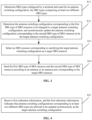
- FIG. 3 is a flowchart showing a method for sending SRS used for antenna switching configuration according to some embodiments. As shown in FIG. 3 , the method for sending SRS used for antenna switching configuration is used in a terminal and includes the following steps.
- step S11 an SRS type configured by the terminal for antenna switching configuration is determined, and the SRS type includes at least two different SRS types.
- step S12 it is determined that an antenna switching configuration corresponding to an SRS resource of the first SRS type is changed to a target antenna switching configuration, and an antenna switching configuration corresponding to an SRS resource of the second SRS type is updated synchronously to the target antenna switching configuration.
- the second SRS type includes all other SRS types different from the first SRS type among at least two different SRS types.
- step S13 an SRS resource corresponding to the target antenna switching configuration is selected as a target SRS resource.
- step S14 the SRS resource of the first SRS type and the SRS resource of the second SRS are sent according to an antenna or an antenna port corresponding to the target SRS resource.
- the SRS types configured by the terminal for antenna switching configuration include at least two SRS types among P-SRS resources, SP-SRS resources and AP-SRS resources.
- the SRS resource of the first SRS type and the SRS resource of the second SRS type are SRS resources of different SRS types.
- the SRS resource of the first SRS type is AP-SRS resource
- the SRS resource of the second SRS type is P-SRS resource or SP-SRS resource.
- the SRS resource of the first SRS type is AP-SRS resource or SP-SRS resource
- the SRS resource of the second SRS type is P-SRS resource.
- the SRS resource of the first SRS type is P-SRS resource
- the SRS resource of the second SRS type is AP-SRS resource or SP-SRS resource.
- the SRS resource of the first SRS type is P-SRS resource or SP-SRS resource
- the SRS resource of the second SRS type is AP-SRS resource.
- the antenna switching configuration corresponding to the SRS resource of the first SRS type is changed to the target antenna switching configuration, and the antenna switching configuration corresponding to the SRS resource of the second SRS type is updated synchronously to the target antenna switching configuration.
- the SRS resource of the first SRS type is AP-SRS
- the SRS resource of the second SRS type is P-SRS/SP-SRS.
- the antenna switching configuration corresponding to AP-SRS is changed, the antenna switching configuration of P-SRS/SP-SRS will be updated synchronously, and the SRS resource in the corresponding SRS resource configuration will be selected to keep that the same Tx/Rx antenna(s) or Tx/Rx antenna port(s) as AP-SRS will be used.
- the SRS resource of the first SRS type is SP-SRS/AP-SRS
- the SRS resource of the second SRS type is P-SRS.
- the antenna switching configuration corresponding to SP-SRS/AP-SRS When the antenna switching configuration corresponding to SP-SRS/AP-SRS is changed, the antenna switching configuration of P-SRS will be updated synchronously, and the SRS resource in the corresponding SRS resource configuration will be selected to keep that the same Tx/Rx antenna(s) or Tx/Rx antenna port(s) as SP-SRS/AP-SRS will be used.
- the SRS resource of the first SRS type is P-SRS
- the SRS resource of the second SRS type is AP-SRS/SP-SRS.
- the antenna switching configuration corresponding to P-SRS is changed, the antenna switching configuration of AP-SRS/SP-SRS is updated synchronously, the SRS resource in the corresponding SRS resource configuration is selected to ensure that the same Tx/Rx antenna(s) or Tx/Rx antenna port(s) as P-SRS is used.
- the SRS resource of the first SRS type is P-SRS/SP-SRS
- the SRS resource of the second SRS type is AP-SRS.
- the antenna switching configuration corresponding to P-SRS/SP-SRS is changed, the antenna switching configuration of AP-SRS is updated synchronously, and the SRS resource in the corresponding SRS resource configuration is selected to ensure that the same Tx/Rx antenna(s) or Tx/Rx antenna port(s) as P-SRS/SP-SRS is used.
- the terminal synchronously updates the antenna switching configurations corresponding to different SRS types.
- the network device allows synchronous updating of antenna switching configurations corresponding to different SRS types
- the antenna switching configurations corresponding to different SRS types can be synchronous updated to the target antenna switching configuration.
- the network may instruct the terminal through signaling to allow the synchronous adaptive updating/synchronization of all configuration types to use the same antenna switching configuration for transmission.
- the indication information which indicates that the antenna switching configurations corresponding to at least two different SRS types are allowed to be updated synchronously as the target antenna switching configuration, is referred to as the first indication information.
- the network device sends the first indication information to the terminal, indicating that the antenna switching configurations corresponding to at least two different SRS types are allowed to be updated synchronously as the target antenna switching configuration.
- the terminal receives the first indication information, and synchronously updates the antenna switching configurations corresponding to the at least two different SRS types as the target antenna switching configuration.
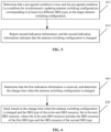
- FIG. 4 is a flow chart of a method for sending SRS used for antenna switching configuration according to some embodiments.
- the method for sending SRS used for antenna switching configuration may be executed alone or in combination with other embodiments.
- the method for sending SRS used for antenna switching configuration is used in a terminal, and includes the following steps.
- step S21 first indication information is received, and the first indication information indicates that antenna switching configurations corresponding to at least two different SRS types are allowed to be updated synchronously as the target antenna switching configuration.
- the first indication information in some embodiments of this disclosure may include at least one of the following: radio resource control (RRC) information, a media access control (MAC) control element (CE), downlink control information (DCI), and grant controller (GC) DCI.
- RRC radio resource control
- MAC media access control
- DCI downlink control information
- GC grant controller
- the terminal can adaptively select, according to a predefined manner and agreement with the network, a corresponding SRS resource within configured SRS resource configuration range of different SRS types, which is to be used for sending the corresponding type of SRS.
- FIG. 5 is a flow chart of an method for sending SRS used for antenna switching configuration according to some embodiments.
- the method for sending SRS used for antenna switching configuration may be executed alone or in combination with other embodiments.
- the method for sending SRS used for antenna switching configuration is used in a terminal, and includes the following steps.
- step S31 it is determined that a pre-agreed condition is met, and the pre-agreed condition is a condition for synchronously updating antenna switching configurations corresponding to at least two different SRS types as the target antenna switching configuration.
- step S32 second indication information is reported, and the second indication information indicates that the antenna switching configuration is changed.
- the pre-agreed condition may be pre-agreed based on the power saving requirement of the terminal, changes in the multiplexing situation of the terminal antenna(s), and the like. For example, based on the power saving requirement, the terminal determines that the pre-agreed condition of the power saving requirement is satisfied, changes the antenna switching configuration, and reports the second indication information, indicating that the antenna switching configuration is changed based on the power saving requirement. The network device receives the second indication information, determines that the terminal changes the antenna switching configuration based on the power saving requirement, and then implements a synchronous acknowledgement on the change of antenna switching configuration.
- the second indication information may include at least one of RRC, MAC CE, DCI, and GC-DCI.
- the terminal synchronously updates the antenna switching configurations of SRS resources of different SRS types to the target antenna switching configuration, and selects the SRS resource corresponding to the target antenna switching configuration as the target SRS resource.
- the terminal for each SRS type in the at least two different SRS types, all or part of the SRS resources conforming to the target antenna switching configuration in the SRS resource configuration corresponding to the each SRS type are reselected as the target SRS resource.
- the SRS resource of the first SRS type and the SRS resource of the second SRS type are sent according to the antenna or antenna port corresponding to the target SRS resource.
- the terminal sends the SRS resource of the first SRS type and the SRS resource of the second SRS type according to the antenna or antenna port corresponding to the target SRS resource, and the SRS resource of the first SRS type and the SRS resource of the second SRS types may be sent in different manners based on different update methods.
- the terminal based on the first indication information, based on the first indication information, the terminal synchronously updates the antenna switching configurations of SRS resources of different SRS types to the target antenna switching configuration, and sends the SRS resource of the first SRS type and the SRS resource of the second SRS type.
- the terminal may send the to-be-sent SRS resource based on the change time when the antenna switching configuration is changed and the SRS type of the to-be-sent SRS resource.
- FIG. 6 is a flow chart of a method for sending SRS used for antenna switching configuration according to some embodiments.
- the method for sending SRS used for antenna switching configuration may be executed alone or in combination with other embodiments.
- the method for sending SRS used for antenna switching configuration is used in a terminal, and includes the following steps.
- step S41 it is determined that the first indication information is received, and the change time when the antenna switching configuration is changed is determined.
- step S42 based on the change time when the antenna switching configuration is changed and the SRS type of the to-be-sent SRS resource, the to-be-sent SRS resource is sent, where the to-be-sent SRS resource includes the SRS resource of the first SRS type and the SRS resource of the second SRS type.
- the SRS type of the to-be-sent SRS resource is P-SRS resource or AP-SRS resource, and the to-be-sent SRS resource is sent at the change time when the antenna switching configuration is changed.
- the SRS type of the to-be-sent SRS resource is SP-SRS resource, and at least one of the following manners is used to send the to-be-sent SRS resource.
- sending of the to-be-sent SRS resource is started at the change time when the antenna switching configuration is changed. It can also be understood as that the SRS transmission is immediately applied when the antenna configuration is changed.
- the to-be-sent SRS resource is sent at a start time of a next sounding sending cycle after a complete sounding is completed based on an SRS resource set corresponding to the sounding sending cycle. It can also be understood as that the SRS transmission is applied after a complete sounding of an SRS resource set.
- the to-be-sent SRS resource is uniformly sent in a next scheduling cycle after an SRS resource set scheduling cycle corresponding to the change time when the antenna switching configuration is changed. It can also be understood as a uniform change being aligned to the next P-SRS transmission time.
- the terminal reports the second indication information based on the pre-agreed condition, and synchronously updates the antenna switching configurations corresponding to at least two different SRS types as the target antenna switching configuration.
- the to-be-sent SRS resource is sent based on the reporting time of the second indication information and the SRS type of the to-be-sent SRS resource.
- FIG. 7 is a flow chart of a method for sending SRS used for antenna switching configuration according to some embodiments.
- the method for sending SRS used for antenna switching configuration may be executed alone or in combination with other embodiments.
- the method for sending SRS used for antenna switching configuration is used in a terminal, and includes the following steps.
- step S51 a reporting time for reporting the second indication information is determined.
- step S52 based on the reporting time of the second indication information and the SRS type of the to-be-sent SRS resource, the to-be-sent SRS resource is sent, where the to-be-sent SRS resource includes the SRS resource of the first SRS type and the SRS resource of the second SRS type.
- the SRS type of the to-be-sent SRS resource is P-SRS resource or AP-SRS resource, and the to-be-sent SRS resource is sent at the reporting time of the second indication information.
- the SRS type of the to-be-sent SRS resource is SP-SRS resource, and at least one of the following manners is used to send the to-be-sent SRS resource.
- the to-be-sent SRS resource is sent at the reporting time of the second indication information. It can also be understood as that the SRS transmission is immediately applied at the reporting time of the second indication information.
- the to-be-sent SRS resource is sent at a start time of a next sounding cycle after sounding is completed based on an SRS resource set corresponding to the reporting time. It can also be understood as that the SRS transmission is applied after a complete sounding of an SRS resource set.
- the to-be-sent SRS resource is uniformly sent in a next scheduling cycle after an SRS resource set scheduling cycle corresponding to the reporting time of the second indication information. It can also be understood as a uniform change being aligned to the next P-SRS transmission time.
- different types of SRS can be synchronized in certain scenarios or requirements, so as to ensure that, when transmitting SRS, the terminal can adaptively select the SRS resource for actual transmission by using the same Tx/Rx chain, thereby actually achieving terminal requirements such as power saving.
- some embodiments of this disclosure further provide a method for sending SRS used for antenna switching configuration performed by a network device.
- FIG. 8 is a flow chart of a method for sending SRS used for antenna switching configuration according to some embodiments.
- the method for sending SRS used for antenna switching configuration may be executed alone or in combination with other embodiments.
- the method for sending SRS used for antenna switching configuration is used in a network device, and includes the following steps.
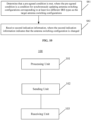
- step S61 the SRS resource of the first SRS type and the SRS resource of the second SRS type are received at the antenna or antenna port corresponding to the target SRS resource.
- the antenna switching configuration corresponding to the SRS resource of the second SRS type is a target antenna switching configuration changed from an antenna switching configuration corresponding to the SRS resource of the first SRS type
- the second SRS type includes all of at least two different SRS types other than the first SRS type
- the target SRS resource conforms to SRS resources corresponding to the target antenna switching configuration
- FIG. 9 is a flow chart showing a method for sending SRS used for antenna switching configuration according to some embodiments.
- the method for sending SRS used for antenna switching configuration may be performed alone or in combination with other embodiments.
- the method for sending SRS used for antenna switching configuration is used in a network device, and includes the following steps.
- step S71 first indication information is sent, and the first indication information indicates that antenna switching configurations corresponding to at least two different SRS types are allowed to be updated synchronously as the target antenna switching configuration.
- the first indication information may include at least one of RRC, MAC CE, DCI, and GC-DCI.
- the network device receives the to-be-received SRS resource based on the change time when the antenna switching configuration is changed and the SRS type of the to-be-received SRS resource, where the to-be-received SRS resource includes the SRS resource of the first SRS type and the SRS resource of the second SRS type.
- the SRS type of the to-be-received SRS resource is P-SRS resource or AP-SRS resource, and the to-be-received SRS resource is received at the change time.
- the SRS type of the to-be-received SRS resource is SP-SRS resource, and at least one of the following manners is used to receive the to-be-received SRS resource.
- the to-be-received SRS resource is received at a start time of a next sounding sending cycle after a complete sounding is completed based on an SRS resource set corresponding to the sounding sending cycle.
- the to-be-sent SRS resource is uniformly received in a next scheduling cycle after an SRS resource set scheduling cycle corresponding to the change time.
- FIG. 10 is a flow chart showing a method for sending SRS used for antenna switching configuration according to some embodiments.
- the method for sending SRS used for antenna switching configuration may be performed alone or in combination with other embodiments.
- the method for sending SRS used for antenna switching configuration is used in network device, including the following steps.
- step S81 it is determined that a pre-agreed condition is met, where the pre-agreed condition is a condition for synchronously updating antenna switching configurations corresponding to at least two different SRS types as the target antenna switching configurations.
- step S82 second indication information is received, where the second indication information indicates that the antenna switching configuration is changed.
- the second indication information may include at least one of RRC, MAC CE, DCI, and GC-DCI.
- the network device determines a reporting time for receiving the second indication information. Based on the reporting time of the second indication information and the SRS type of the to-be-received SRS resource, the to-be-received SRS resource is received, where the to-be-received SRS resource includes the SRS resource of the first SRS type and the SRS resource of the second SRS type.
- the SRS type of the to-be-received SRS resource is P-SRS resource or AP-SRS resource, and the to-be-received SRS resource is received at the reporting time.
- the SRS type of the to-be-received SRS resource is SP-SRS resource, and at least one of the following manners is used to receive the to-be-received SRS resource.
- the to-be-received SRS resource is received at the reporting time of the second indication information.
- the to-be-received SRS resource is received at a start time of a next sounding cycle after sounding is completed based on an SRS resource set corresponding to the reporting time.
- the to-be-received SRS resource is uniformly received in a next scheduling cycle after an SRS resource set scheduling cycle corresponding to the reporting time.
- the SRS resource of the first SRS type is AP-SRS resource
- the SRS resource of the second SRS type is P-SRS resources or SP-SRS resource
- the SRS resource of the first SRS type is AP-SRS resource or SP-SRS resource
- the SRS resource of the second SRS type is P-SRS resource.
- the SRS resource of the first SRS type is P-SRS resource
- the SRS resource of the second SRS type is AP-SRS resource or SP-SRS resource
- the SRS resource of the first SRS type is P-SRS resource or SP-SRS resource
- the SRS resource of the second SRS type is AP-SRS resource.
- the method for sending SRS used for antenna switching configuration is applicable to interacting between the terminal and the network device to implement transmission of SRS for antenna switching configuration.
- the terminal has the functions of realizing the terminal involved in the above-mentioned embodiments
- the network device has the functions of realizing the network device involved in the above-mentioned embodiments.
- the above-mentioned embodiments can be referred to, and relevant descriptions will not be described in detail here.
- some embodiments of this disclosure further provide an apparatus for sending SRS used for antenna switching configuration.
- the apparatus for sending SRS used for antenna switching configuration includes corresponding hardware structures and/or software modules for performing various functions.
- the embodiments of this disclosure may be implemented in the form of hardware or a combination of hardware and computer software. Whether a certain function is executed by hardware or computer software driving hardware depends on the specific application and design constraints of the technical solution. Those skilled in the art may use different methods to implement the described functions for each specific application, but such implementation should not be regarded as exceeding the scope of the technical solutions according to the embodiments of this disclosure.
- FIG. 11 is a block diagram of an apparatus for sending SRS used for antenna switching configuration according to some embodiments.
- the apparatus 100 for sending SRS used for antenna switching configuration is applied to a terminal, and includes a processing unit 101 and a sending unit 102.
- the processing unit 101 is configured to determine an SRS type configured by a terminal for antenna switching configuration, where the SRS type includes at least two different SRS types; determine that an antenna switching configuration corresponding to an SRS resource of a first SRS type is changed to a target antenna switching configuration, and synchronously update an antenna switching configuration corresponding to an SRS resource of a second SRS type as the target antenna switching configuration, where the second SRS type includes all of the at least two different SRS types other than the first SRS type; and select an SRS resource corresponding to the target antenna switching configuration as a target SRS resource.
- the sending unit 102 is configured to send the SRS resource of the first SRS type and the SRS resource of the second SRS type based on an antenna or an antenna port corresponding to the target SRS resource.
- the apparatus 100 for sending SRS used for antenna switching configuration further includes a receiving unit 103, and the receiving unit 103 is configured to receive first indication information, where the first indication information indicates permission of synchronously updating antenna switching configurations corresponding to the at least two different SRS types as the target antenna switching configuration.
- the sending unit 102 is configured to send the SRS resource of the first SRS type and the SRS resource of the second SRS type in the following manner: determining that the receiving unit 103 receives the first indication information, determining a change time when the antenna switching configuration is changed; and sending a to-be-sent SRS resource based on the change time and an SRS type of the to-be-sent SRS resource, where the to-be-sent SRS resource includes the SRS resource of the first SRS type and the SRS resource of the second SRS type.
- the sending unit 102 is configured to send the to-be-sent SRS resource based on the change time and the SRS type of the to-be-sent SRS resource in a following manner: determining that the SRS type of the to-be-sent SRS resource is P-SRS resource or AP-SRS resource, and sending the to-be-sent SRS resource at the change time.
- the sending unit 102 is configured to send the to-be-sent SRS resource based on the change time and the SRS type of the to-be-sent SRS resource by determining that the SRS type of the to-be-sent SRS resource is SP-SRS resource, and sending the to-be-sent SRS resource in at least one of following manners: starting sending of the to-be-sent SRS resource at the change time; in response to that the change time is in a sounding sending cycle in which SRS has already started, sending, after a complete sounding is completed based on an SRS resource set corresponding to the sounding sending cycle, the to-be-sent SRS resource at a start time of a next sounding sending cycle; or uniformly sending the to-be-sent SRS resource in a next scheduling cycle after an SRS resource set scheduling cycle corresponding to the change time.
- the processing unit 101 is further configured to: determine that a pre-agreed condition is met, where the pre-agreed condition is a condition for synchronously updating antenna switching configurations corresponding to the at least two different SRS types as the target antenna switching configuration; and the sending unit 102 is further configured to report second indication information, where the second indication information indicates that the antenna switching configuration is changed.
- the sending unit 102 is configured to send the SRS resource of the first SRS type and the SRS resource of the second SRS type in a following manner: determining a reporting time for reporting the second indication information; and sending a to-be-sent SRS resource based on the reporting time and an SRS type of the to-be-sent SRS resource, where the to-be-sent SRS resource includes the SRS resource of the first SRS type and the SRS resource of the second SRS type.
- the sending unit 102 is configured to send the to-be-sent SRS resource based on the reporting time and an SRS type of the to-be-sent SRS resource in a following manner: determining that the SRS type of the to-be-sent SRS resource is P-SRS resource or AP-SRS resource, and sending the to-be-sent SRS resource at the reporting time.
- the sending unit 102 is configured to send the to-be-sent SRS resource based on the reporting time and an SRS type of the to-be-sent SRS resource by determining that the SRS type of the to-be-sent SRS resource is SP-SRS resource, and sending the to-be-sent SRS resource in at least one of the following manners: sending the to-be-sent SRS resource at the reporting time; sending the to-be-sent SRS resource at a start time of a next sounding cycle after sounding is completed based on an SRS resource set corresponding to the reporting time; or uniformly sending the to-be-sent SRS resource in a next scheduling cycle after an SRS resource set scheduling cycle corresponding to the reporting time.
- the processing unit 101 is configured to select the SRS resource corresponding to the target antenna switching configuration as the target SRS resource in a following manner: for each SRS type in the at least two different SRS types, reselecting, in an SRS resource configuration corresponding to the each SRS type, all or part of SRS resources conforming to the target antenna switching configuration as the target SRS resource.
- the SRS resource of the first SRS type is AP-SRS resource
- the SRS resource of the second SRS type is P-SRS resource or SP-SRS resource
- the SRS resource of the first type is AP-SRS resource or SP-SRS resource
- the SRS resource of the second SRS type is a P-SRS resource.
- the SRS resource of the first SRS type is P-SRS resource
- the SRS resource of the second SRS type is AP-SRS resource or SP-SRS resource
- the SRS resource of the first type is P-SRS resource or SP-SRS resource
- the SRS resource of the second SRS type is AP-SRS resource.
- the first indication information or the second indication information includes at least one of the following: MAC CE, DCI, CG-DCI, and RRC.
- FIG. 12 is a block diagram of an apparatus for sending SRS used for antenna switching configuration according to some embodiments.
- the apparatus 200 for sending SRS used for antenna switching configuration is applied to a network device, including a receiving unit 201.
- the receiving unit 201 is configured to receive an SRS resource of a first SRS type and an SRS resource of a second SRS type at an antenna or an antenna port corresponding to a target SRS resource; where an antenna switching configuration corresponding to the SRS resource of the second SRS type is a target antenna switching configuration changed from an antenna switching configuration corresponding to the SRS resource of the first SRS type, the second SRS type includes all of at least two different SRS types other than the first SRS type, and the target SRS resource conforms to SRS resources corresponding to the target antenna switching configuration.
- the apparatus 200 for sending SRS used for antenna switching configuration further includes a sending unit 202, and the sending unit 202 is configured to send first indication information, where the first indication information indicates permission of synchronously updating antenna switching configurations corresponding to the at least two different SRS types as the target antenna switching configuration.
- the receiving unit 201 is configured to receive the SRS resource of the first SRS type and the SRS resource of the second SRS type in a following manner: receiving a to-be-received SRS resource based on a change time when the antenna switching configuration is changed and an SRS type of the to-be-received SRS resource, where the to-be-received SRS resource includes the SRS resource of the first SRS type and the SRS resource of the second SRS type.
- the receiving unit 201 is configured to receive the to-be-received SRS resource based on the change time when the antenna switching configuration is changed and the SRS type of the to-be-received SRS resource in a following manner: determining that the SRS type of the to-be-received SRS resource is P-SRS resource or AP-SRS resource, and receiving the to-be-received SRS resource at the change time.
- the receiving unit 201 is configured to receive the to-be-received SRS resource based on the change time when the antenna switching configuration is changed and the SRS type of the to-be-received SRS resource by determining that the SRS type of the to-be-received SRS resource is a SP-SRS resource, and receiving the to-be-received SRS resource in at least one of following manners: starting receiving of the to-be-received SRS resource at the change time; in response to that the change time is in a sounding sending cycle in which SRS has already started, receiving, after a complete sounding is completed based on an SRS resource set corresponding to the sounding sending cycle, the to-be-received SRS resource at a start time of a next sounding sending cycle; or uniformly receiving the to-be-sent SRS resource in a next scheduling cycle after an SRS resource set scheduling cycle corresponding to the change time.
- the receiving unit 201 is further configured to: determine that a pre-agreed condition is met, where the pre-agreed condition is a condition for synchronously updating antenna switching configurations corresponding to the at least two different SRS types as the target antenna switching configuration; and receive second indication information, where the second indication information indicates that the antenna switching configuration is changed.
- the receiving unit 201 is configured to receive the SRS resource of the first SRS type and the SRS resource of the second SRS type in a following manner: determining a reporting time for receiving the second indication information; and receiving a to-be-received SRS resource based on the reporting time and an SRS type of the to-be-received SRS resource, where the to-be-received SRS resource includes the SRS resource of the first SRS type and the SRS resource of the second SRS type.
- the receiving unit 201 is configured to receive the to-be-received SRS resource based on the reporting time and the SRS type of the to-be-received SRS resource in a following manner: determining that the SRS type of the to-be-received SRS resource is P-SRS resource or AP-SRS resource, and receiving the to-be-received SRS resource at the reporting time.
- the receiving unit 201 is configured to receive the to-be-received SRS resource based on the reporting time and the SRS type of the to-be-received SRS resource by: determining that the SRS type of the to-be-received SRS resource is SP-SRS resource, and receiving the to-be-received SRS resource in at least one of following manners: receiving the to-be-received SRS resource at the reporting time; receiving the to-be-received SRS resource at a start time of a next sounding cycle after sounding is completed based on an SRS resource set corresponding to the reporting time; or uniformly receiving the to-be-received SRS resource in a next scheduling cycle after an SRS resource set scheduling cycle corresponding to the reporting time.
- the SRS resource of the first SRS type is AP-SRS resource
- the SRS resource of the second SRS type is P-SRS resource or SP-SRS resource
- the SRS resource of the first SRS type is AP-SRS resource or SP-SRS resource
- the SRS resource of the second SRS type is P-SRS resource.
- the SRS resource of the first SRS type is P-SRS resource
- the SRS resource of the second SRS type is AP-SRS resource or SP-SRS resource
- the SRS resource of the first SRS type is P-SRS resource or SP-SRS resource
- the SRS resource of the second SRS type is AP-SRS resource.
- the first indication information or the second indication information includes at least one of the following: MAC CE, DCI, CG-DCI and RRC information.
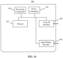
- FIG. 13 is a block diagram showing a device for sending SRS used for antenna switching configuration according to some embodiments.
- the device 300 may be provided as a terminal.
- the device 300 may be a mobile phone, a computer, a digital broadcast terminal, a messaging device, a game console, a tablet device, a medical device, a fitness device, a personal digital assistant, and the like.
- the device 300 may include one or more of the following components: processing component 302, memory 304, power component 306, multimedia component 308, audio component 310, input/output (I/O) interface 312, sensor component 314, and communication component 316.
- the processing component 302 generally controls the overall operation of the device 300, such as operations associated with display, phone calls, data communications, camera operations, and recording operations.
- the processing component 302 may include one or more processors 320 to execute instructions to perform all or some of the steps of the methods described above. Additionally, the processing component 302 may include one or more modules that facilitate interaction between the processing component 302 and other components. For example, the processing component 302 may include a multimedia module to facilitate interaction between the multimedia component 308 and the processing component 302.
- the memory 304 is configured to store various types of data to support operation at the device 300. Examples of such data include instructions, contact data, phonebook data, messages, pictures, videos, and the like for any application or method operating on the device 300.
- the memory 304 may be implemented by any type of volatile or non-volatile storage device or combination thereof, such as static random access memory (SRAM), electrically erasable programmable read only memory (EEPROM), erasable programmable read only memory (EPROM), programmable read only memory (PROM), read only memory (ROM), magnetic memory, flash memory, magnetic or optical disk.
- SRAM static random access memory
- EEPROM electrically erasable programmable read only memory
- EPROM erasable programmable read only memory
- PROM programmable read only memory
- ROM read only memory
- magnetic memory flash memory
- flash memory magnetic or optical disk.
- the power component 306 provides power to various components of the device 300.
- the power components 306 may include a power management system, one or more power sources, and other components associated with generating, managing, and distributing power to the device 300.
- the multimedia component 308 includes a screen that provides an output interface between the device 300 and the user.
- the screen may include a liquid crystal display (LCD) and a touch panel (TP). If the screen includes a touch panel, the screen may be implemented as a touch screen to receive input signals from a user.
- the touch panel includes one or more touch sensors to sense touch, swipe, and gestures on the touch panel. The touch sensor may not only sense the boundaries of a touch or swipe action, but also detect the duration and pressure associated with the touch or swipe action.
- the multimedia component 308 includes a front camera and/or a rear camera. When the device 300 is in an operation mode, such as a shooting mode or a video mode, the front camera and/or the rear camera may receive external multimedia data. Each of the front and rear cameras may be a fixed optical lens system or have focal length and optical zoom capability.
- the audio component 310 is configured to output and/or input audio signals.
- the audio component 310 includes a microphone (MIC) that is configured to receive external audio signals when the device 300 is in operating modes, such as calling mode, recording mode, and voice recognition mode.
- the received audio signal may be further stored in the memory 304 or transmitted via the communication component 316.
- the audio component 310 also includes a speaker for outputting audio signals.
- the I/O interface 312 provides an interface between the processing component 302 and a peripheral interface module, which may be a keyboard, a click wheel, a button, or the like. These buttons may include, but are not limited to: home button, volume buttons, start button, and lock button.
- the sensor assembly 314 includes one or more sensors for providing status assessments of various aspects of the device 300.
- the sensor assembly 314 can detect the open/closed state of the device 300, the relative positioning of components, such as the display and keypad of the device 300.
- the sensor assembly 314 can also detect a change in the position of the device 300 or a component of the device 300, the presence or absence of user contact with the device 300, the orientation or acceleration/deceleration of the device 300, and the temperature change of the device 300.
- the sensor assembly 314 may include a proximity sensor configured to detect the presence of nearby objects in the absence of any physical contact.
- the sensor assembly 314 may also include a light sensor, such as a CMOS or CCD image sensor, for use in imaging applications.
- the sensor assembly 314 may also include an acceleration sensor, a gyroscope sensor, a magnetic sensor, a pressure sensor, or a temperature sensor.
- the communication component 316 is configured to facilitate wired or wireless communication between the device 300 and other devices.
- the device 300 may access wireless networks based on communication standards, such as WiFi, 2G or 3G, or a combination thereof.
- the communication component 316 receives broadcast signals or broadcast related information from an external broadcast management system via a broadcast channel.
- the communication component 316 also includes a near field communication (NFC) module to facilitate short-range communication.
- NFC near field communication
- the NFC module may be implemented based on radio frequency identification (RFID) technology, infrared data association (IrDA) technology, ultra-wideband (UWB) technology, Bluetooth (BT) technology and other technologies.
- RFID radio frequency identification
- IrDA infrared data association
- UWB ultra-wideband
- Bluetooth Bluetooth
- the device 300 may be implemented by one or more application specific integrated circuits (ASICs), digital signal processors (DSPs), digital signal processing devices (DSPDs), programmable logic devices (PLDs), field programmable gate array (FPGA), controller, microcontroller, microprocessor or other electronic component, which are configured to perform the forgoing methods.
- ASICs application specific integrated circuits
- DSPs digital signal processors
- DSPDs digital signal processing devices
- PLDs programmable logic devices
- FPGA field programmable gate array
- controller microcontroller, microprocessor or other electronic component, which are configured to perform the forgoing methods.
- non-transitory computer-readable storage medium including instructions, such as the memory 304 including instructions, executable by the processor 320 of the device 300 to perform the method described above.
- the non-transitory computer-readable storage medium may be ROM, random access memory (RAM), CD-ROM, magnetic tape, floppy disk, optical data storage device, and the like.
- FIG. 14 is a block diagram showing a device for sending SRS used for antenna switching configuration according to some embodiments.
- the device 400 may be provided as a network device.
- the device 400 includes a processing component 422, which further includes one or more processors; and a memory resource represented by memory 432 for storing instructions executable by the processing component 422, such as application programs.
- the application program stored in memory 432 may include one or more modules each corresponding to a set of instructions.
- the processing component 422 is configured to execute instructions to perform the forgoing methods.
- the device 400 may also include a power component 426 configured to perform power management of the device 400, a wired or wireless network interface 450 configured to connect the device 400 to a network, and an input-output (I/O) interface 458.
- the device 400 can operate based on an operating system stored in the memory 432, such as Windows Server TM , Mac OS X TM , Unix TM , Linux TM , FreeBSD TM or the like.
- non-transitory computer-readable storage medium including instructions, such as the memory 432 including instructions, which may be executed by the processing component 422 of the device 400 to implement the forgoing methods.
- the non-transitory computer readable storage medium may be ROM, RAM, CD-ROM, magnetic tape, floppy disk, optical data storage device, and the like.
- plural of / multiple in this disclosure refers to two or more, and other quantifiers are similar thereto.
- the term “and/or” describes the association relationship of associated objects, indicating that there may be three types of relationships. For example, A and/or B may indicate: A exists alone, both A and B exist, and B exists alone.
- the character “/” generally indicates that the contextual objects are in an “or” relationship.
- the singular forms “a”, “said” and “the” are also intended to include the plural unless the context clearly indicates otherwise.
- first, second, and the like are used to describe various information, but the information should not be limited to these terms. These terms are only used to distinguish information of the same type from one another, and do not imply a specific order or degree of importance. In fact, expressions such as “first” and “second” may be used interchangeably.
- first information may also be called second information, and similarly, second information may also be called first information.
Landscapes
- Engineering & Computer Science (AREA)
- Signal Processing (AREA)
- Computer Networks & Wireless Communication (AREA)
- Quality & Reliability (AREA)
- Mobile Radio Communication Systems (AREA)
Applications Claiming Priority (1)
| Application Number | Priority Date | Filing Date | Title |
|---|---|---|---|
| PCT/CN2021/120011 WO2023044684A1 (zh) | 2021-09-23 | 2021-09-23 | 一种用于天线切换配置的srs发送方法、装置及存储介质 |
Publications (2)
| Publication Number | Publication Date |
|---|---|
| EP4408094A1 true EP4408094A1 (de) | 2024-07-31 |
| EP4408094A4 EP4408094A4 (de) | 2025-05-21 |
Family
ID=85719174
Family Applications (1)
| Application Number | Title | Priority Date | Filing Date |
|---|---|---|---|
| EP21957820.0A Withdrawn EP4408094A4 (de) | 2021-09-23 | 2021-09-23 | Srs-sendeverfahren und -vorrichtung zur antennenschaltkonfiguration und speichermedium |
Country Status (4)
| Country | Link |
|---|---|
| US (1) | US12627340B2 (de) |
| EP (1) | EP4408094A4 (de) |
| CN (1) | CN116158041B (de) |
| WO (1) | WO2023044684A1 (de) |
Families Citing this family (3)
| Publication number | Priority date | Publication date | Assignee | Title |
|---|---|---|---|---|
| CN117544211B (zh) * | 2024-01-08 | 2024-04-05 | 深圳旷世科技有限公司 | 基于uwb多天线的数据传输方法、装置、终端及存储介质 |
| WO2025147812A1 (zh) * | 2024-01-08 | 2025-07-17 | 深圳旷世科技有限公司 | 基于uwb多天线的数据传输方法、装置、终端及存储介质 |
| KR20260092153A (ko) * | 2024-12-11 | 2026-06-18 | 삼성전자주식회사 | 상향링크 기준 신호를 전송 또는 수신하는 방법 및 장치 |
Family Cites Families (7)
| Publication number | Priority date | Publication date | Assignee | Title |
|---|---|---|---|---|
| US11032048B2 (en) | 2018-05-18 | 2021-06-08 | Qualcomm Incorporated | Use-cases and constraints on multiple SRS resource sets for antenna switching in NR REL-15 |
| US11456896B2 (en) * | 2018-12-20 | 2022-09-27 | Qualcomm Incorporated | RRC configuration for aperiodic SRS on additional SRS symbols |
| US20230047048A1 (en) | 2020-02-14 | 2023-02-16 | Lenovo (Beijing) Ltd. | Sounding reference signals (srs) for antenna switching |
| EP4084385B1 (de) | 2020-02-19 | 2024-04-24 | Guangdong Oppo Mobile Telecommunications Corp., Ltd. | Antennenschaltverfahren, endgerät und kommunikationsvorrichtung |
| WO2021258242A1 (en) * | 2020-06-22 | 2021-12-30 | Qualcomm Incorporated | Support of flexible sounding reference signal switching capability |
| WO2022087952A1 (en) * | 2020-10-29 | 2022-05-05 | Qualcomm Incorporated | Techniques for indicating sounding reference signal resources |
| EP4278454B1 (de) * | 2021-01-12 | 2026-05-20 | InterDigital Patent Holdings, Inc. | Verfahren, vorrichtungen und systeme in bezug auf sounding-referenzsignalantennenumschaltung |
-
2021
- 2021-09-23 EP EP21957820.0A patent/EP4408094A4/de not_active Withdrawn
- 2021-09-23 US US18/692,391 patent/US12627340B2/en active Active
- 2021-09-23 WO PCT/CN2021/120011 patent/WO2023044684A1/zh not_active Ceased
- 2021-09-23 CN CN202180003030.6A patent/CN116158041B/zh active Active
Also Published As
| Publication number | Publication date |
|---|---|
| WO2023044684A1 (zh) | 2023-03-30 |
| US12627340B2 (en) | 2026-05-12 |
| CN116158041A (zh) | 2023-05-23 |
| CN116158041B (zh) | 2025-10-10 |
| US20240388340A1 (en) | 2024-11-21 |
| EP4408094A4 (de) | 2025-05-21 |
Similar Documents
| Publication | Publication Date | Title |
|---|---|---|
| EP4106437A1 (de) | Datenübertragungsverfahren und datenübertragungsvorrichtung | |
| US20240063979A1 (en) | Beam indication method, beam indication apparatus and storage medium | |
| KR20230155581A (ko) | 대역폭 부분 설정 방법, 대역폭 부분 설정 장치 및 저장 매체(bandwidth part configuration method, bandwidth part configuration apparatus, and storage medium) | |
| US12156207B2 (en) | Method and apparatus for resource allocation, and storage medium | |
| US12317104B2 (en) | Method and device for allocating beam failure request resources | |
| US12627340B2 (en) | SRS sending method and apparatus for antenna switching configuration, and storage medium | |
| US20250031158A1 (en) | Srs power control method and apparatus, and storage medium | |
| CN114938704A (zh) | 一种传输用户设备能力的方法、装置及可读存储介质 | |
| CN112997564A (zh) | 带宽部分切换方法、装置及通信设备 | |
| US12597979B2 (en) | Beam determining method and apparatus, and storage medium | |
| US20240314772A1 (en) | Communication method for uplink transmission of pusch with cg | |
| US20240106504A1 (en) | Methods for switching antenna switching configuration, and communication device | |
| EP4661557A1 (de) | Strahlanzeigeverfahren, -vorrichtung und -vorrichtung sowie speichermedium | |
| EP4550734A1 (de) | Verfahren und vorrichtung zur übertragung von hilfsinformationen und lesbares speichermedium | |
| US20250008356A1 (en) | Method for monitoring or sending pdcch, and device for monitoring pdcch | |
| CN114731510A (zh) | 一种传输终端能力的方法、装置及可读存储介质 | |
| EP4668970A1 (de) | Verfahren, vorrichtung und vorrichtung zur konfiguration einer übertragungskonfigurationsanzeige und speichermedium | |
| EP4611467A1 (de) | Verfahren und vorrichtung zur übertragung von konfigurationsinformationen und lesbares speichermedium | |
| EP4554288A1 (de) | Verfahren und vorrichtung zur übertragung von anweisungsinformationen und lesbares speichermedium | |
| US20250343720A1 (en) | Guard gap configuration method and apparatus, and communication device and storage medium | |
| US20240251395A1 (en) | Method for transmitting capability of user equipment | |
| WO2023122984A1 (zh) | 一种srs触发方法、装置及存储介质 | |
| US20240405958A1 (en) | Srs sending method and apparatus for antenna switching configuration, and storage medium | |
| EP4668898A1 (de) | Verfahren und vorrichtung zur konfiguration von leistungssteuerungsparametern und speichermedium | |
| US20240172232A1 (en) | Method and apparatus for transmitting scheduling interval information, and readable storage medium |
Legal Events
| Date | Code | Title | Description |
|---|---|---|---|
| STAA | Information on the status of an ep patent application or granted ep patent |
Free format text: STATUS: THE INTERNATIONAL PUBLICATION HAS BEEN MADE |
|
| PUAI | Public reference made under article 153(3) epc to a published international application that has entered the european phase |
Free format text: ORIGINAL CODE: 0009012 |
|
| STAA | Information on the status of an ep patent application or granted ep patent |
Free format text: STATUS: REQUEST FOR EXAMINATION WAS MADE |
|
| 17P | Request for examination filed |
Effective date: 20240327 |
|
| AK | Designated contracting states |
Kind code of ref document: A1 Designated state(s): AL AT BE BG CH CY CZ DE DK EE ES FI FR GB GR HR HU IE IS IT LI LT LU LV MC MK MT NL NO PL PT RO RS SE SI SK SM TR |
|
| DAV | Request for validation of the european patent (deleted) | ||
| DAX | Request for extension of the european patent (deleted) | ||
| A4 | Supplementary search report drawn up and despatched |
Effective date: 20250424 |
|
| RIC1 | Information provided on ipc code assigned before grant |
Ipc: H04B 7/06 20060101ALI20250416BHEP Ipc: H04B 7/0404 20170101ALI20250416BHEP Ipc: H04L 5/00 20060101ALI20250416BHEP Ipc: H04W 72/04 20230101AFI20250416BHEP |
|
| STAA | Information on the status of an ep patent application or granted ep patent |
Free format text: STATUS: THE APPLICATION HAS BEEN WITHDRAWN |
|
| 18W | Application withdrawn |
Effective date: 20260309 |