EP4408055A1 - Signalsendeverfahren, signalempfangsverfahren und kommunikationsvorrichtung - Google Patents
Signalsendeverfahren, signalempfangsverfahren und kommunikationsvorrichtung Download PDFInfo
- Publication number
- EP4408055A1 EP4408055A1 EP22874858.8A EP22874858A EP4408055A1 EP 4408055 A1 EP4408055 A1 EP 4408055A1 EP 22874858 A EP22874858 A EP 22874858A EP 4408055 A1 EP4408055 A1 EP 4408055A1
- Authority
- EP
- European Patent Office
- Prior art keywords
- ssb
- terminal device
- bwp
- type terminal
- transmit power
- Prior art date
- Legal status (The legal status is an assumption and is not a legal conclusion. Google has not performed a legal analysis and makes no representation as to the accuracy of the status listed.)
- Pending
Links
- 238000004891 communication Methods 0.000 title claims abstract description 133
- 238000000034 method Methods 0.000 title claims abstract description 127
- 238000005259 measurement Methods 0.000 claims description 97
- 238000003860 storage Methods 0.000 claims description 23
- 238000004590 computer program Methods 0.000 claims description 22
- 230000005540 biological transmission Effects 0.000 abstract description 75
- 235000019527 sweetened beverage Nutrition 0.000 description 609
- 230000006870 function Effects 0.000 description 65
- 238000012545 processing Methods 0.000 description 45
- 230000008569 process Effects 0.000 description 29
- 230000015654 memory Effects 0.000 description 24
- 238000010586 diagram Methods 0.000 description 16
- 230000011664 signaling Effects 0.000 description 13
- 238000005516 engineering process Methods 0.000 description 10
- 238000013507 mapping Methods 0.000 description 10
- 201000003042 peeling skin syndrome Diseases 0.000 description 10
- 229920001467 poly(styrenesulfonates) Polymers 0.000 description 10
- 230000002776 aggregation Effects 0.000 description 7
- 238000004220 aggregation Methods 0.000 description 7
- 238000010295 mobile communication Methods 0.000 description 7
- 230000004044 response Effects 0.000 description 7
- 230000008859 change Effects 0.000 description 6
- 238000013461 design Methods 0.000 description 6
- 230000007774 longterm Effects 0.000 description 6
- 101100274486 Mus musculus Cited2 gene Proteins 0.000 description 3
- 101150096622 Smr2 gene Proteins 0.000 description 3
- 230000003190 augmentative effect Effects 0.000 description 3
- 230000008878 coupling Effects 0.000 description 3
- 238000010168 coupling process Methods 0.000 description 3
- 238000005859 coupling reaction Methods 0.000 description 3
- 230000008054 signal transmission Effects 0.000 description 3
- 230000006399 behavior Effects 0.000 description 2
- 230000009286 beneficial effect Effects 0.000 description 2
- 238000006243 chemical reaction Methods 0.000 description 2
- 238000005265 energy consumption Methods 0.000 description 2
- 230000003993 interaction Effects 0.000 description 2
- 238000004519 manufacturing process Methods 0.000 description 2
- 238000012986 modification Methods 0.000 description 2
- 230000004048 modification Effects 0.000 description 2
- 238000012544 monitoring process Methods 0.000 description 2
- 238000001228 spectrum Methods 0.000 description 2
- 101150096310 SIB1 gene Proteins 0.000 description 1
- 238000013528 artificial neural network Methods 0.000 description 1
- 230000010267 cellular communication Effects 0.000 description 1
- 230000001413 cellular effect Effects 0.000 description 1
- 239000013256 coordination polymer Substances 0.000 description 1
- 230000007423 decrease Effects 0.000 description 1
- 238000011161 development Methods 0.000 description 1
- 235000019800 disodium phosphate Nutrition 0.000 description 1
- 239000011521 glass Substances 0.000 description 1
- 230000003287 optical effect Effects 0.000 description 1
- 230000000737 periodic effect Effects 0.000 description 1
- 230000008439 repair process Effects 0.000 description 1
- 238000001356 surgical procedure Methods 0.000 description 1
Images


Classifications
-
- H—ELECTRICITY
- H04—ELECTRIC COMMUNICATION TECHNIQUE
- H04W—WIRELESS COMMUNICATION NETWORKS
- H04W24/00—Supervisory, monitoring or testing arrangements
- H04W24/02—Arrangements for optimising operational condition
-
- H—ELECTRICITY
- H04—ELECTRIC COMMUNICATION TECHNIQUE
- H04J—MULTIPLEX COMMUNICATION
- H04J11/00—Orthogonal multiplex systems, e.g. using WALSH codes
- H04J11/0069—Cell search, i.e. determining cell identity [cell-ID]
-
- H—ELECTRICITY
- H04—ELECTRIC COMMUNICATION TECHNIQUE
- H04W—WIRELESS COMMUNICATION NETWORKS
- H04W72/00—Local resource management
- H04W72/50—Allocation or scheduling criteria for wireless resources
- H04W72/54—Allocation or scheduling criteria for wireless resources based on quality criteria
- H04W72/542—Allocation or scheduling criteria for wireless resources based on quality criteria using measured or perceived quality
-
- H—ELECTRICITY
- H04—ELECTRIC COMMUNICATION TECHNIQUE
- H04J—MULTIPLEX COMMUNICATION
- H04J11/00—Orthogonal multiplex systems, e.g. using WALSH codes
- H04J11/0069—Cell search, i.e. determining cell identity [cell-ID]
- H04J11/0073—Acquisition of primary synchronisation channel, e.g. detection of cell-ID within cell-ID group
-
- H—ELECTRICITY
- H04—ELECTRIC COMMUNICATION TECHNIQUE
- H04J—MULTIPLEX COMMUNICATION
- H04J11/00—Orthogonal multiplex systems, e.g. using WALSH codes
- H04J11/0069—Cell search, i.e. determining cell identity [cell-ID]
- H04J11/0076—Acquisition of secondary synchronisation channel, e.g. detection of cell-ID group
-
- H—ELECTRICITY
- H04—ELECTRIC COMMUNICATION TECHNIQUE
- H04L—TRANSMISSION OF DIGITAL INFORMATION, e.g. TELEGRAPHIC COMMUNICATION
- H04L5/00—Arrangements affording multiple use of the transmission path
- H04L5/0001—Arrangements for dividing the transmission path
- H04L5/0003—Two-dimensional division
- H04L5/0005—Time-frequency
- H04L5/0007—Time-frequency the frequencies being orthogonal, e.g. OFDM(A) or DMT
- H04L5/001—Time-frequency the frequencies being orthogonal, e.g. OFDM(A) or DMT the frequencies being arranged in component carriers
-
- H—ELECTRICITY
- H04—ELECTRIC COMMUNICATION TECHNIQUE
- H04L—TRANSMISSION OF DIGITAL INFORMATION, e.g. TELEGRAPHIC COMMUNICATION
- H04L5/00—Arrangements affording multiple use of the transmission path
- H04L5/003—Arrangements for allocating sub-channels of the transmission path
- H04L5/0048—Allocation of pilot signals, i.e. of signals known to the receiver
- H04L5/005—Allocation of pilot signals, i.e. of signals known to the receiver of common pilots, i.e. pilots destined for multiple users or terminals
-
- H—ELECTRICITY
- H04—ELECTRIC COMMUNICATION TECHNIQUE
- H04L—TRANSMISSION OF DIGITAL INFORMATION, e.g. TELEGRAPHIC COMMUNICATION
- H04L5/00—Arrangements affording multiple use of the transmission path
- H04L5/0091—Signalling for the administration of the divided path, e.g. signalling of configuration information
- H04L5/0094—Indication of how sub-channels of the path are allocated
-
- H—ELECTRICITY
- H04—ELECTRIC COMMUNICATION TECHNIQUE
- H04L—TRANSMISSION OF DIGITAL INFORMATION, e.g. TELEGRAPHIC COMMUNICATION
- H04L5/00—Arrangements affording multiple use of the transmission path
- H04L5/0091—Signalling for the administration of the divided path, e.g. signalling of configuration information
- H04L5/0096—Indication of changes in allocation
-
- H—ELECTRICITY
- H04—ELECTRIC COMMUNICATION TECHNIQUE
- H04W—WIRELESS COMMUNICATION NETWORKS
- H04W24/00—Supervisory, monitoring or testing arrangements
- H04W24/08—Testing, supervising or monitoring using real traffic
-
- H—ELECTRICITY
- H04—ELECTRIC COMMUNICATION TECHNIQUE
- H04W—WIRELESS COMMUNICATION NETWORKS
- H04W4/00—Services specially adapted for wireless communication networks; Facilities therefor
- H04W4/70—Services for machine-to-machine communication [M2M] or machine type communication [MTC]
-
- H—ELECTRICITY
- H04—ELECTRIC COMMUNICATION TECHNIQUE
- H04W—WIRELESS COMMUNICATION NETWORKS
- H04W48/00—Access restriction; Network selection; Access point selection
- H04W48/08—Access restriction or access information delivery, e.g. discovery data delivery
- H04W48/10—Access restriction or access information delivery, e.g. discovery data delivery using broadcasted information
-
- H—ELECTRICITY
- H04—ELECTRIC COMMUNICATION TECHNIQUE
- H04W—WIRELESS COMMUNICATION NETWORKS
- H04W52/00—Power management, e.g. Transmission Power Control [TPC] or power classes
- H04W52/02—Power saving arrangements
-
- H—ELECTRICITY
- H04—ELECTRIC COMMUNICATION TECHNIQUE
- H04W—WIRELESS COMMUNICATION NETWORKS
- H04W52/00—Power management, e.g. Transmission Power Control [TPC] or power classes
- H04W52/02—Power saving arrangements
- H04W52/0209—Power saving arrangements in terminal devices
- H04W52/0212—Power saving arrangements in terminal devices managed by the network, e.g. network or access point is leader and terminal is follower
- H04W52/0219—Power saving arrangements in terminal devices managed by the network, e.g. network or access point is leader and terminal is follower where the power saving management affects multiple terminals
-
- H—ELECTRICITY
- H04—ELECTRIC COMMUNICATION TECHNIQUE
- H04W—WIRELESS COMMUNICATION NETWORKS
- H04W52/00—Power management, e.g. Transmission Power Control [TPC] or power classes
- H04W52/04—Transmission power control [TPC]
- H04W52/18—TPC being performed according to specific parameters
- H04W52/22—TPC being performed according to specific parameters taking into account previous information or commands
- H04W52/225—Calculation of statistics, e.g. average or variance
-
- H—ELECTRICITY
- H04—ELECTRIC COMMUNICATION TECHNIQUE
- H04W—WIRELESS COMMUNICATION NETWORKS
- H04W52/00—Power management, e.g. Transmission Power Control [TPC] or power classes
- H04W52/04—Transmission power control [TPC]
- H04W52/30—Transmission power control [TPC] using constraints in the total amount of available transmission power
- H04W52/32—TPC of broadcast or control channels
- H04W52/322—Power control of broadcast channels
-
- H—ELECTRICITY
- H04—ELECTRIC COMMUNICATION TECHNIQUE
- H04W—WIRELESS COMMUNICATION NETWORKS
- H04W52/00—Power management, e.g. Transmission Power Control [TPC] or power classes
- H04W52/04—Transmission power control [TPC]
- H04W52/30—Transmission power control [TPC] using constraints in the total amount of available transmission power
- H04W52/32—TPC of broadcast or control channels
- H04W52/325—Power control of control or pilot channels
-
- H—ELECTRICITY
- H04—ELECTRIC COMMUNICATION TECHNIQUE
- H04W—WIRELESS COMMUNICATION NETWORKS
- H04W52/00—Power management, e.g. Transmission Power Control [TPC] or power classes
- H04W52/04—Transmission power control [TPC]
- H04W52/30—Transmission power control [TPC] using constraints in the total amount of available transmission power
- H04W52/34—TPC management, i.e. sharing limited amount of power among users or channels or data types, e.g. cell loading
- H04W52/346—TPC management, i.e. sharing limited amount of power among users or channels or data types, e.g. cell loading distributing total power among users or channels
-
- H—ELECTRICITY
- H04—ELECTRIC COMMUNICATION TECHNIQUE
- H04W—WIRELESS COMMUNICATION NETWORKS
- H04W72/00—Local resource management
- H04W72/04—Wireless resource allocation
- H04W72/044—Wireless resource allocation based on the type of the allocated resource
- H04W72/0446—Resources in time domain, e.g. slots or frames
-
- H—ELECTRICITY
- H04—ELECTRIC COMMUNICATION TECHNIQUE
- H04W—WIRELESS COMMUNICATION NETWORKS
- H04W72/00—Local resource management
- H04W72/04—Wireless resource allocation
- H04W72/044—Wireless resource allocation based on the type of the allocated resource
- H04W72/0453—Resources in frequency domain, e.g. a carrier in FDMA
-
- H—ELECTRICITY
- H04—ELECTRIC COMMUNICATION TECHNIQUE
- H04W—WIRELESS COMMUNICATION NETWORKS
- H04W72/00—Local resource management
- H04W72/04—Wireless resource allocation
- H04W72/044—Wireless resource allocation based on the type of the allocated resource
- H04W72/0457—Variable allocation of band or rate
-
- H—ELECTRICITY
- H04—ELECTRIC COMMUNICATION TECHNIQUE
- H04W—WIRELESS COMMUNICATION NETWORKS
- H04W72/00—Local resource management
- H04W72/20—Control channels or signalling for resource management
- H04W72/23—Control channels or signalling for resource management in the downlink direction of a wireless link, i.e. towards a terminal
-
- H—ELECTRICITY
- H04—ELECTRIC COMMUNICATION TECHNIQUE
- H04W—WIRELESS COMMUNICATION NETWORKS
- H04W72/00—Local resource management
- H04W72/50—Allocation or scheduling criteria for wireless resources
- H04W72/51—Allocation or scheduling criteria for wireless resources based on terminal or device properties
-
- H—ELECTRICITY
- H04—ELECTRIC COMMUNICATION TECHNIQUE
- H04L—TRANSMISSION OF DIGITAL INFORMATION, e.g. TELEGRAPHIC COMMUNICATION
- H04L5/00—Arrangements affording multiple use of the transmission path
- H04L5/0001—Arrangements for dividing the transmission path
- H04L5/0014—Three-dimensional division
- H04L5/0023—Time-frequency-space
-
- H—ELECTRICITY
- H04—ELECTRIC COMMUNICATION TECHNIQUE
- H04L—TRANSMISSION OF DIGITAL INFORMATION, e.g. TELEGRAPHIC COMMUNICATION
- H04L5/00—Arrangements affording multiple use of the transmission path
- H04L5/003—Arrangements for allocating sub-channels of the transmission path
- H04L5/0053—Allocation of signalling, i.e. of overhead other than pilot signals
-
- H—ELECTRICITY
- H04—ELECTRIC COMMUNICATION TECHNIQUE
- H04L—TRANSMISSION OF DIGITAL INFORMATION, e.g. TELEGRAPHIC COMMUNICATION
- H04L5/00—Arrangements affording multiple use of the transmission path
- H04L5/0091—Signalling for the administration of the divided path, e.g. signalling of configuration information
- H04L5/0092—Indication of how the channel is divided
-
- H—ELECTRICITY
- H04—ELECTRIC COMMUNICATION TECHNIQUE
- H04L—TRANSMISSION OF DIGITAL INFORMATION, e.g. TELEGRAPHIC COMMUNICATION
- H04L5/00—Arrangements affording multiple use of the transmission path
- H04L5/0091—Signalling for the administration of the divided path, e.g. signalling of configuration information
- H04L5/0096—Indication of changes in allocation
- H04L5/0098—Signalling of the activation or deactivation of component carriers, subcarriers or frequency bands
-
- Y—GENERAL TAGGING OF NEW TECHNOLOGICAL DEVELOPMENTS; GENERAL TAGGING OF CROSS-SECTIONAL TECHNOLOGIES SPANNING OVER SEVERAL SECTIONS OF THE IPC; TECHNICAL SUBJECTS COVERED BY FORMER USPC CROSS-REFERENCE ART COLLECTIONS [XRACs] AND DIGESTS
- Y02—TECHNOLOGIES OR APPLICATIONS FOR MITIGATION OR ADAPTATION AGAINST CLIMATE CHANGE
- Y02D—CLIMATE CHANGE MITIGATION TECHNOLOGIES IN INFORMATION AND COMMUNICATION TECHNOLOGIES [ICT], I.E. INFORMATION AND COMMUNICATION TECHNOLOGIES AIMING AT THE REDUCTION OF THEIR OWN ENERGY USE
- Y02D30/00—Reducing energy consumption in communication networks
- Y02D30/70—Reducing energy consumption in communication networks in wireless communication networks
Definitions
- This application relates to the field of mobile communication technologies, and in particular, to a signal sending method, a signal receiving method, and a communication apparatus.
- Typical mMTC services include, for example, an industrial wireless sensor network (industrial wireless sensor network, IWSN) service, a video surveillance (video surveillance) service, and a wearables (wearables) service.
- IWSN industrial wireless sensor network
- video surveillance video surveillance
- wearables wearables
- Different services have different requirements on capabilities of terminal devices. For example, a service that does not require a high data transmission rate may be implemented by a machine-type terminal device that has a weak capability and that is implemented with low costs. Therefore, compared with a common terminal device, the machine-type terminal device can reduce an implementation specification, to reduce implementation costs.
- a network device usually broadcasts a synchronization signal and physical broadcast channel block (synchronization signal and (physical broadcast channel, PBCH) block, SSB), which is used by a terminal device to initially access a cell and so on. Because the common terminal device and the machine-type terminal device have different capabilities, the network device configures different initial downlink bandwidth parts (bandwidth parts, BWPs) for the common terminal device and the machine-type terminal device. For example, the network device configures a first BWP for the common terminal device, and configures a second BWP for the machine-type terminal device. The network device may send an SSB in the first BWP, and the common terminal device and the machine-type terminal device may receive the SSB in the first BWP.
- BWPs bandwidth parts
- the network device may also send an SSB in the second BWP.
- the machine-type terminal device needs to receive the SSB only in the second BWP, and does not need to switch from the second BWP to the first BWP, to reduce energy consumption.
- power of the SSB is usually higher than power of another channel (or signal).
- a power spectrum density (power spectrum density, PSD) on a time-frequency resource carrying the SSB is higher than a PSD on a time-frequency resource carrying the another channel (or signal). It may be understood that power on a same time-frequency resource is fixed. If an additional SSB is introduced on a time-frequency resource, a PSD of another channel (or signal) on the time-frequency resource is reduced. As a result, transmission performance of the another channel (or signal) is low.
- the network device sends the SSBs in the first BWP and the second BWP, transmission performance of another channel or signal within a bandwidth range of the first BWP and the second BWP is low.
- This application provides a signal sending method, a signal receiving method, and a communication apparatus, to reduce impact of introduction of an additional SSB on transmission performance of another channel or signal.
- a signal sending method may be performed by a first communication apparatus.
- the first communication apparatus may be a communication device or a communication apparatus that can support the communication device in implementing a function required by the method, for example, a chip system.
- An example in which the communication device is a network device is used below for description.
- the method includes the following steps.
- the network device determines a first SSB and a second SSB, sends the first SSB on a first BWP, and sends the second SSB on a second BWP. Transmit power of the first SSB is different from transmit power of the second SSB. Alternatively, a sum of the transmit power of the first SSB and the transmit power of the second SSB is the same in a first time unit and a second time unit.
- a signal receiving method is provided, and may be performed by a second communication apparatus.
- the second communication apparatus may be a communication device or a communication apparatus that can support the communication device in implementing a function required by the method, for example, a chip system.
- An example in which the communication device is a terminal device is used below for description.
- the method includes the following steps.
- the terminal device receives a first SSB on a first BWP, and/or receives a second SSB on a second BWP. Then, the terminal device performs measurement based on the first SSB and/or the second SSB, for example, performs radio resource management (radio resource management, RRM) measurement or radio link management (radio link management, RLM) measurement. Transmit power of the first SSB is different from transmit power of the second SSB. Alternatively, a sum of the transmit power of the first SSB and the transmit power of the second SSB is the same in a first time unit and a second time unit.
- radio resource management radio resource management
- RLM radio link management
- the network device can configure BWPs separately for different types of terminal devices (for example, a first-type terminal device and a second-type terminal device), for example, configure the first BWP for the first-type terminal device and the second BWP for the second-type terminal device.
- the network device may send the first SSB in the first BWP, and send the second SSB in the second BWP.
- the technical solution of this application can be used to avoid high power consumption caused because that the second-type terminal device frequently switches from the second BWP to the first BWP to obtain an SSB from the network device.
- the second SSB may be directly sent in the second BWP, that is, a quantity of BWP switching times may be reduced, to reduce power consumption of the terminal device.
- the transmit power of the first SSB is allowed to be different from the transmit power of the second SSB.
- the network device may configure the transmit power of the second SSB to be lower than the transmit power of the first SSB. In this way, a total PSD on the bandwidth in which the first BWP and the second BWP are located can be reduced as much as possible, to reduce impact on transmission performance of another channel or signal within a range of the bandwidth.
- the sum of the transmit power of the first SSB and the transmit power of the second SSB is the same in the first time unit and the second time unit. In other words, total power of the transmit power of the first SSB and the transmit power of the second SSB remains unchanged. In this way, it can be avoided that transmit power of one SSB in the transmit power of the first SSB and the transmit power of the second SSB is always higher than transmit power of the other SSB. For a terminal device that receives an SSB with lower transmit power, transmission performance can be improved.
- the first SSB and the second SSB have the following correspondence:
- the transmit power of the first SSB is different from the transmit power of the second SSB in a same time unit, the transmit power of the first SSB varies in different time units, and the transmit power of the second SSB varies in different time units.
- the transmit power of the first SSB is allowed to be different in the different time units.
- the network device may adjust the transmit power of the first SSB based on a service requirement of the first-type terminal device, so that the transmit power of the first SSB adapts to an actual service requirement of the first-type terminal device, to increase a service transmission rate of the first-type terminal device.
- the transmit power of the second SSB is allowed to be different in different time units, and the transmit power of the second SSB may be adjusted based on an actual service requirement of the second-type terminal device, to increase a service transmission rate of the second-type terminal device.
- the transmit power of the first SSB is allowed to be different from the transmit power of the second SSB in a same time unit, to reduce impact on transmission performance of another channel or signal on a time-frequency resource that carries the first SSB and the second SSB.
- the network device may flexibly adjust the transmit power of the first SSB and the transmit power of the second SSB based on an actual requirement, to improve transmission performance of the terminal device as much as possible, and reduce the impact on the transmission performance of the another channel or signal.
- the first SSB and the second SSB have the following correspondence: A time domain resource occupied by the first SSB is different from a time domain resource occupied by the second SSB. It may be understood that, if the time domain resource occupied by the first SSB is the same as the time domain resource occupied by the second SSB, transmit power of a signal on a time-frequency resource in which the time domain resource is located is high. In this case, a PSD of another channel or signal on the time-frequency resource is lower.
- the time domain resource occupied by the first SSB is allowed to be different from the time domain resource occupied by the second SSB, and total transmit power of the first SSB and the second SSB of the signal on the time-frequency resource in which the time domain resource is located can be reduced as much as possible. Therefore, impact on transmission performance of the another channel or signal on the time-frequency resource is further reduced.
- the terminal device may receive the first SSB and the second SSB in a time division manner, to obtain more SSBs in a same time unit, so that an obtained measurement result of the SSB is more accurate, and transmission performance of the terminal device is improved.
- the network device may configure the time domain resource occupied by the first SSB and the time domain resource occupied by the second SSB based on one or more of the following implementation forms. This is more flexible.
- Implementation form 1 A time domain position of a synchronization signal burst of the first SSB is different from a time domain position of a synchronization signal burst of the second SSB.
- Implementation form 2 A sending periodicity of the first SSB is different from a sending periodicity of the second SSB.
- the time domain resource occupied by the first SSB may be different from the time domain resource occupied by the second SSB.
- the network device may flexibly adjust the sending periodicity of the first SSB and/or the sending periodicity of the second SSB based on an actual energy saving requirement of the terminal device, to reduce power consumption of the terminal device as much as possible. For example, compared with the second-type terminal device, the first-type terminal device has a lower requirement on power consumption. In this case, the sending periodicity of the first SSB is larger than the sending periodicity of the second SSB, to meet a low power consumption requirement of the second-type terminal device.
- Implementation form 3 A quantity of SSB beams in a synchronization signal burst of the first SSB is different from a quantity of SSB beams in a synchronization signal burst of the second SSB.
- different quantities of SSB beams are configured, so that the time domain resource occupied by the first SSB is different from the time domain resource occupied by the second SSB.
- different quantities of SSB beams are allowed to be configured, so that the time domain resource occupied by the first SSB is different from the time domain resource occupied by the second SSB. Therefore, the network device may adjust, based on coverage performance of the terminal device, a quantity of SSB beams corresponding to the terminal device, to increase a service transmission rate of the terminal device within coverage as much as possible.
- the transmit power of the first SSB is at least one of the following power: power of an SSS, power of a PSS, power of a PBCH, or power of a demodulation reference signal (demodulation reference signal, DMRS) used for the PBCH.
- transmit power of the SSB is not limited.
- the transmit power of the SSB may be the power of the SSS, the power of the PSS, or the like.
- the method further includes: The network device sends indication information.
- the terminal device receives the indication information.
- the indication information indicates the transmit power of the second SSB.
- the indication information indicates a power offset, and the power offset is a difference between the transmit power of the second SSB and the transmit power of the first SSB.
- the network device may notify the transmit power of the second SSB to the terminal device, to assist the terminal device in inferring a path loss of a sent signal based on the transmit power, so that transmit power of a to-be-sent signal is flexibly adjusted, and signal transmission reliability is improved.
- the network device may directly indicate the transmit power of the second SSB.
- the indication information includes the transmit power of the second SSB.
- the network device may indirectly indicate the transmit power of the second SSB.
- the indication information includes the difference between the transmit power of the second SSB and the transmit power of the first SSB: the power offset. It may be understood that, if the network device does not send the indication information, it may be considered by default that the transmit power of the second SSB is the same as the transmit power of the first SSB.
- the terminal device may perform RRM measurement based on a received SSB.
- the network device sends the first SSB in the first BWP, and also sends the second SSB in the second BWP.
- the second-type terminal device may receive the first SSB in the first BWP, and may also receive the second SSB in the second BWP.
- an SSB used for the RRM measurement is an SSB in a BWP in which a paging resource is located. In other words, the paging resource is located in the first BWP, and the SSB used for the RRM measurement is the first SSB.
- the paging resource is located in the second BWP, and the SSB used for the RRM measurement is the second SSB. If the paging resource is located in the first BWP and the second BWP, the SSB used for the RRM measurement may be the first SSB and/or the second SSB. Correspondingly, if the second-type terminal device determines that the paging resource is located in the first BWP, the second-type terminal device performs the RRM measurement based on the first SSB. If the second-type terminal device determines that the paging resource is located in the second BWP, the second-type terminal device performs the RRM measurement based on the second SSB.
- the second-type terminal device determines that the paging resource is located in the first BWP and the second BWP, the second-type terminal device performs the RRM measurement based on the first SSB and the second SSB. In this way, it can be ensured that the second-type terminal device performs the RRM measurement in a process of monitoring paging, and does not need to perform BWP switching, to reduce power consumption of the second-type terminal device.
- transmit power of the SSB used for the RRM measurement is greater than a preset threshold. It may be understood that, if the transmit power of the SSB is low, accuracy of a measurement result obtained based on the SSB is low. Therefore, accuracy of determining cell coverage is also low. Therefore, in embodiments of this application, it is specified that only an SSB whose transmit power is higher than the preset threshold is used for the RRM measurement. This can improve the accuracy of determining the cell coverage.
- the transmit power of the SSB used for the RRM measurement may be lower than the preset threshold.
- an actual measurement result of the SSB may be adjusted, and an adjusted measurement result is used as a final RRM measurement result.
- the RRM measurement result is a sum of the measurement result of the SSB and an offset
- the offset is related to the transmit power of the first SSB and the transmit power of the second SSB.
- the offset is a difference between the transmit power of the first SSB and the transmit power of the second SSB.
- the method further includes: The network device sends first information in the first BWP and/or the second BWP.
- the method further includes: The terminal device receives the first information in the first BWP and/or the second BWP.
- the first information includes a paging message, a system message, a random access response message, or a contention resolution message.
- a DMRS antenna port of a physical downlink shared channel (physical downlink shared channel, PDSCH) that carries the first information has a QCL relationship with the first SSB or the second SSB, and/or a DMRS antenna port of a physical downlink control channel (physical downlink control channel, PDCCH) for scheduling the first information has a QCL relationship with the first SSB or the second SSB.
- the terminal device may infer, based on an SSB that has a QCL relationship with a channel for sending the first information, some characteristics of the channel for sending the first information.
- the second SSB is additionally introduced, both the first SSB and the second SSB exist.
- the terminal device may infer, based on the first SSB or the second SSB, the some characteristics of the channel for sending the first information. Therefore, it is specified in this solution that the DMRS antenna port of the PDSCH that carries the first information has the QCL relationship with the first SSB or the second SSB, or the DMRS antenna port of the PDCCH for scheduling the first information has the QCL relationship with the first SSB or the second SSB.
- an SSB having the QCL relationship with the DMRS antenna port of the PDSCH that carries the first information or the DMRS antenna port of the PDCCH for scheduling the first information may be determined based on the first information and a BWP that carries the first information.
- the first information is a system message or a paging message.
- the BWP that carries the first information is the first BWP
- the DMRS antenna port of the PDSCH that carries the first information has the QCL relationship with the first SSB, and/or the DMRS antenna port of the PDCCH for scheduling the first information has the QCL relationship with the first SSB.
- the BWP that carries the first information is the second BWP
- the DMRS antenna port of the PDSCH that carries the first information has the QCL relationship with the second SSB
- the DMRS antenna port of the PDCCH for scheduling the first information has the QCL relationship with the second SSB.
- the first information is a random access response message or a contention resolution message
- the first BWP and the second BWP respectively correspond to different random access channel occasions (random access channel occasions, ROs).
- the BWP that carries the first information is the first BWP
- the DMRS antenna port of the PDSCH that carries the first information has the QCL relationship with the first SSB
- the DMRS antenna port of the PDCCH for scheduling the first information has the QCL relationship with the first SSB.
- the DMRS antenna port of the PDSCH that carries the first information has the QCL relationship with the second SSB, and/or the DMRS antenna port of the PDCCH for scheduling the first information has the QCL relationship with the second SSB.
- the first information is a random access response message or a contention resolution message, but the first BWP and the second BWP share a first RO.
- the network device configures a mapping relationship between the first SSB and the first RO, the DMRS antenna port of the PDSCH that carries the first information has the QCL relationship with the first SSB, and/or the DMRS antenna port of the PDCCH for scheduling the first information has the QCL relationship with the first SSB.
- the network device configures the mapping relationship between the first SSB and the first RO and a mapping relationship between the second SSB and the first RO, and the BWP that carries the first information is the first BWP, the DMRS antenna port of the PDSCH that carries the first information has the QCL relationship with the first SSB, and/or the DMRS antenna port of the PDCCH for scheduling the first information has the QCL relationship with the first SSB.
- the network device configures the mapping relationship between the first SSB and the first RO and the mapping relationship between the second SSB and the first RO, and the BWP that carries the first information is the second BWP, the DMRS antenna port of the PDSCH that carries the first information has the QCL relationship with the second SSB, and/or the DMRS antenna port of the PDCCH for scheduling the first information has the QCL relationship with the second SSB.
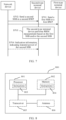
- a communication apparatus has a function of implementing behavior in the method instance of the first aspect.
- the function may be implemented by hardware, or may be implemented by the hardware by executing corresponding software.
- the hardware or the software includes one or more modules corresponding to the foregoing function.
- the communication apparatus includes a processing module and/or a transceiver module. These modules may perform corresponding functions in the method example of the first aspect. For details, refer to detailed descriptions in the method example. Details are not described herein again.
- a communication apparatus has a function of implementing behavior in the method instance of the second aspect.
- the function may be implemented by hardware, or may be implemented by the hardware by executing corresponding software.
- the hardware or the software includes one or more modules corresponding to the foregoing function.
- the communication apparatus includes a processing module and/or a transceiver module. These modules may perform corresponding functions in the method example of the second aspect. For details, refer to detailed descriptions in the method example. Details are not described herein again.
- a communication apparatus may be the terminal device in the foregoing method embodiments, or may be a chip disposed in the terminal device.
- the communication apparatus includes a communication interface and a processor, and optionally, further includes a memory.
- the memory is configured to store a computer program or instructions.
- the processor is coupled to the memory and the communication interface. When the processor executes the computer program or the instructions, the communication apparatus is enabled to perform the method performed by the terminal device in the foregoing method embodiments.
- a communication apparatus may be the network device in the foregoing method embodiments, or may be a chip disposed in the network device.
- the communication apparatus includes a communication interface and a processor, and optionally, further includes a memory.
- the memory is configured to store a computer program or instructions.
- the processor is coupled to the memory and the communication interface. When the processor executes the computer program or the instructions, the communication apparatus is enabled to perform the method performed by the network device in the foregoing method embodiments.
- a computer program product includes computer program code.
- the computer program product includes computer program code.
- a computer program product includes computer program code.
- the computer program product includes computer program code.
- this application provides a chip system.
- the chip system includes a processor, configured to implement a function of the terminal device in the methods in the foregoing aspects.
- the chip system further includes a memory, configured to store program instructions and/or data.
- the chip system may include a chip, or may include the chip and another discrete component.
- this application provides a chip system.
- the chip system includes a processor, configured to implement a function of the network device in the methods in the foregoing aspects.
- the chip system further includes a memory, configured to store program instructions and/or data.
- the chip system may include a chip, or may include the chip and another discrete component.
- this application provides a computer-readable storage medium.
- the computer-readable storage medium stores a computer program.
- the computer program is run, the method performed by the terminal device in the foregoing aspects is implemented.
- this application provides a computer-readable storage medium.
- the computer-readable storage medium stores a computer program.
- the computer program is run, the method performed by the network device in the foregoing aspects is implemented.
- the network device may further include a core network device.
- the core network device includes, for example, an access and mobility management function (access and mobility management function, AMF), a user plane function (user plane function, UPF), or the like.
- AMF access and mobility management function
- UPF user plane function
- An access network device is mainly used in embodiments of this application. Therefore, in the following descriptions, unless otherwise specified, the network device refers to the access network device.
- an apparatus configured to implement a function of the network device may be a network device, or may be an apparatus, for example, a circuit system, that can support the network device in implementing the function.
- the apparatus may be mounted in the network device.
- an example in which the apparatus configured to implement the function of the network device may be the network device is used to describe the technical solutions provided in embodiments of this application.
- a terminal device is a device having wireless receiving and sending functions, and may send a signal to the network device or receive a signal from the network device.
- the terminal device may be referred to as a user equipment (user equipment, UE), and may also be referred to as a terminal, an access station, a UE station, a remote station, a wireless communication device, a user apparatus, or the like.
- the terminal device is configured to connect a person, an object, a machine, and the like, and may be widely used in various scenarios, for example, including but not limited to the following scenarios: cellular communication, D2D, V2X, machine-to-machine/machine type communication (machine-to-machine/machine type communication, M2M/MTC), an internet of things (internet of things, IoT), virtual reality (virtual reality, VR), augmented reality (augmented reality, AR), industrial control (industrial control), self driving (self driving), remote medical (remote medical), a smart grid (smart grid), smart furniture, smart office, smart wearables, smart transportation, a smart city (smart city), an unmanned aerial vehicle, and a robot.
- cellular communication D2D, V2X
- machine-to-machine/machine type communication machine-to-machine/machine type communication
- M2M/MTC machine-to-machine/machine type communication
- IoT internet of things
- virtual reality virtual reality
- the terminal device in embodiments of this application may be a device used in one or more of the foregoing scenarios.
- the terminal device may alternatively be a wearable device, for example, glasses, gloves, a watch, clothing, and shoes.
- the terminal device may further include a relay (relay).
- the terminal device may be customer terminal equipment (customer premise equipment, CPE).
- CPE customer premise equipment
- the CPE may receive a signal from the network device, and forward the signal to another terminal device.
- any device that can perform data communication with the base station may be considered as a terminal device.
- the vehicle-mounted terminal device is also referred to as, for example, an on board unit (on board unit, OBU).
- OBU on board unit
- the terminal device may be an apparatus configured to implement a function of the terminal, or may be an apparatus that can support the terminal device in implementing the function, for example, a chip system.
- the apparatus may be mounted in the terminal device.
- the terminal device may alternatively be a vehicle detector.
- the chip system may include a chip, or may include the chip and another discrete component.
- a plurality of different types of terminal devices are used in embodiments of this application.
- the plurality of different types of terminal devices may be classified based on capabilities of the terminal devices or service types supported by the terminal devices.
- Terminal devices having different capabilities may support different service types.
- the International Telecommunication Union International Telecommunication Union, ITU
- the three types of application scenarios are: eMBB, URLLC, and mMTC.
- Typical eMBB services include an ultra high-definition video, augmented reality AR, virtual reality VR, and the like. These services are mainly characterized by a large amount of transmitted data and a high transmission rate.
- Typical URLLC services include wireless control in an industrial manufacturing or production process, motion control and remote repair of a self-driving car and an unmanned aerial vehicle, a tactile interaction application such as remote surgery, and the like. These services are mainly characterized by ultra-high reliability, a low latency, a small amount of transmitted data, and burstiness.
- Typical mMTC services include an IWSN service, a video surveillance service, a wearables service, and the like. These services are mainly characterized by a large quantity of network-connected devices, a small amount of transmitted data, and insensitivity of data to a transmission latency. These mMTC terminals need to satisfy requirements of low costs and extremely long standby duration.
- a service that does not require a high data transmission rate may be implemented by using a machine-type terminal device that has a weak capability and that is implemented with low costs.
- the IWSN service is met when a data transmission rate carried by a sensor in an IWSN is less than or equal to 2 Mbps, and a data transmission rate carried by an economical video surveillance camera is usually 2 Mbps to 4 Mbps.
- a downlink peak rate of a terminal device in the wearables service for example, a smart watch, does not exceed 150 Mbps, and an uplink peak rate of the terminal device does not exceed 50 Mbps, which are far lower than peak rates of an NR common (legacy) terminal device (for example, an NR eMBB terminal device).
- the machine-type terminal device can reduce an implementation specification, to reduce implementation costs.
- the terminal devices may be classified into a plurality of types of terminals.
- a terminal device that supports a service requiring a high data transmission rate may be referred to as a first-type terminal device
- a terminal device that supports a service requiring a low data transmission rate may be referred to as a second-type terminal device.
- the second-type terminal device may be considered as a terminal device with lower complexity or a reduced capability.
- the second-type terminal device may be less complex than the first-type terminal device in terms of supported bandwidth, power consumption, and antenna quantity. For example, narrower bandwidth, lower power consumption, and fewer antennas are supported.
- the first-type terminal device may also be referred to as a normal terminal device or a terminal device having a legacy capability or/normal capability/high capability, and may also be referred to as a legacy (legacy) terminal device.
- the second-type terminal device may be referred to as a machine-type terminal device, a terminal device having low complexity or a reduced capability (REDuced CAPability, REDCAP), a terminal device having a reduced capability, or an (NR light, NRL) terminal device, namely, a lightweight terminal device.
- the terminal device in embodiments of this application may be the first-type terminal device, or may be the second-type terminal device.
- the second-type terminal device is a low-complexity terminal device
- the first-type terminal device may be a terminal device other than the low-complexity terminal device.
- a difference between the first-type terminal device and the second-type terminal device includes at least one of the following items.
- the foregoing descriptions are merely examples, and there may be another difference between the first-type terminal device and the second-type terminal device.
- the first-type terminal device does not support coverage enhancement
- the second-type terminal device supports the coverage enhancement
- the first-type terminal device does not support small packet transmission
- the second-type terminal device supports the small packet transmission. Examples are not described herein one by one.
- the BWP refers to a segment of contiguous frequency resources in frequency domain.
- the BWP may be classified into an uplink BWP and a downlink BWP.
- the uplink BWP is used by the terminal device to perform uplink sending, and bandwidth of the uplink BWP may exceed a sending bandwidth capability of the terminal device.
- the downlink BWP is used by the terminal device to perform downlink receiving, and bandwidth of the downlink BWP may exceed a receiving bandwidth capability of the terminal device.
- a bandwidth capability of the terminal device may be channel bandwidth supported by the terminal device, maximum channel bandwidth supported by the terminal device, a quantity of resource blocks (resource blocks, RBs) supported by the terminal device, or a maximum quantity of resource blocks supported by the terminal device. It may be understood that bandwidth of a BWP of the first-type terminal device may exceed a bandwidth capability of the second-type terminal device, that is, exceeds maximum bandwidth supported by the second-type terminal device.
- One terminal device may be configured with one or more BWPs. However, in a same period of time, the terminal device can operate in only one of the BWPs, and the BWP may also be considered as a BWP activated by the terminal device.
- the terminal device When the terminal device is configured with a plurality of BWPs, the terminal device may switch between the plurality of BWPs.
- a BWP configured by the network device for the terminal device may be referred to as an initial BWP, for example, an initial downlink BWP or an initial uplink BWP.
- Frequency tuning means that when the network device communicates with the terminal device, a radio frequency component in the network device and a radio frequency component in the terminal device operate within a specific frequency range. Center frequencies at which the radio frequency components operate may determine frequency resource positions at which the network device and the terminal device operate. If an operating frequency range of the radio frequency component changes, for example, the terminal device switches from one BWP to another BWP, a frequency domain position and/or bandwidth for operation of the radio frequency component change/changes, the radio frequency component needs to perform frequency tuning, to change the center frequency, so as to change a position for receiving/sending a frequency resource. The frequency tuning needs to occupy a period of tuning time. Within the tuning time, the network device and the terminal device cannot send or receive information.
- a synchronization signal is used for 2 and frequency synchronization between the terminal device and the network device when the terminal device accesses the network.
- a synchronization signal is transmitted by using an SSB as a basic unit.
- the SSB includes a primary synchronization signal (primary synchronization signal, PSS) and a secondary synchronization signal (secondary synchronization signal, SSS).
- PSS primary synchronization signal
- SSS secondary synchronization signal
- the terminal device may perform time and frequency synchronization with the network device by using the PSS and SSS.
- the SSB may further include a PBCH.
- the PBCH mainly carries broadcast information, including a master information block (master information block, MIB) from a higher layer and timing-related information from a physical layer.
- the SSB may further be used for channel quality measurement, RRM measurement, RLM measurement, or the like.
- the NR system supports the network device in sending SSBs on a plurality of beams.
- Different frequency bands support different quantities of beams.
- the network device may support a maximum of eight SSB beams. That is, the network device may send eight SSBs to the terminal device in a same period of time.
- transmission of the plurality of SSBs is completed in one half-frame, and periodic transmission may be performed in the half-frame for transmission of the SSB. In other words, the network device periodically sends the SSB.
- a set including all SSBs sent within one periodicity may be referred to as a synchronization signal burst (synchronization signal burst, SS burst).
- a periodicity of the SS burst may be set to 5 ms (milliseconds), 10 ms, 20 ms, 40 ms, 80 ms, 160 ms, or the like.
- 20 ms is a default periodicity, that is, a periodicity assumed when the terminal device performs initial cell search.
- Quasi co-location may be understood as that large-scale parameters of a channel through which a symbol on an antenna port passes may be inferred from a channel through which a symbol on another antenna port passes.
- the large-scale parameters may include a latency spread, an average latency, a Doppler spread, a Doppler shift, an average gain, a spatial reception parameter, and the like.
- the two antenna ports have a QCL relationship. This may also be referred to as that the two antenna ports are quasi co-located.
- a DMRS antenna port of a PDSCH has the QCL relationship with an antenna port of another signal.
- a DMRS antenna port of a PDCCH has the QCL relationship with an antenna port of another signal.
- that a DMRS antenna port of a PDSCH has the QCL relationship with an antenna port of another signal is also referred to as that the DMRS antenna port of the PDSCH has the QCL relationship with the another signal, or that the DMRS has the QCL relationship with the another signal.
- a DMRS antenna port of a PDCCH has the QCL relationship with an antenna port of another signal is also referred to as that the DMRS antenna port of the PDCCH has the QCL relationship with the another signal.
- that an antenna port has the QCL relationship with a signal means that the antenna port has the QCL relationship with an antenna port of the signal.
- At least one means one or more, and "a plurality of" means two or more.
- the term “and/or” describes an association relationship between associated objects and indicates that three relationships may exist. For example, A and/or B may indicate the following three cases: Only A exists, both A and B exist, and only B exists. A and B each may be singular or plural.
- the character “/” usually indicates an "or” relationship between the associated objects.
- At least one item (piece) of the following” or a similar expression thereof means any combination of these items, including a singular item (piece) or any combination of plural items (pieces).
- At least one (piece) of a, b, or c may indicate: a; b; c; a and b; a and c; b and c; or a, b, and c, where a, b, and c may be singular or plural.
- ordinal numbers such as “first” and “second” mentioned in embodiments of this application are used to distinguish between a plurality of objects, and are not used to limit a sequence, a time sequence, a priority, or an importance degree of the plurality of obj ects.
- the first BWP and the second BWP are merely used to distinguish between different BWPs, and do not indicate different precedence, different importance, or the like of the two BWPs.
- "if” and “assuming” may be replaced with each other, “when” and “in a case of” may be replaced with each other, and “RRM measurement” and “RLM measurement” may be replaced with each other.
- 5th generation 5th generation, 5G
- 5G 5th generation
- LTE long term evolution
- next-generation mobile communication system or another similar communication system This is not specifically limited.
- FIG. 1 shows a network architecture used in an embodiment of this application.
- FIG. 1 includes a network device and six terminal devices.
- the six terminal devices may be a cellular phone, a smartphone, a portable computer, a handheld communication device, a handheld computing device, a satellite radio apparatus, a global positioning system, a PDA, and/or any other appropriate device used for communication on a wireless communication system, and all may be connected to the network device.
- the six terminal devices all can communicate with the network device.
- a quantity of the terminal devices in FIG. 1 is merely an example.
- FIG. 1 is merely an example, and types of devices included in the communication system are not limited in this embodiment of this application.
- the communication system may further include another network device, for example, a wireless relay device or a wireless backhaul device.
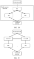
- FIG. 2A shows a communication network architecture in a communication system provided in this application. All subsequent embodiments shown in FIG. 4 are applicable to the architecture.
- a first network device is a source network device (or referred to as a working network device or a serving network device) of a terminal device (where a UE is used as an example subsequently for description).
- a second network device is a target network device (or referred to as a standby network device) of the UE, that is, a network device that serves the UE after switching.
- “fault” may be understood as that the network device is faulty, and/or the network device cannot serve one or more UEs due to other reasons, which is referred to as a fault for short.
- the “switching” in this application means that the network device serving the UE switches, and is not limited to "cell switching".
- the “switching” may refer to switching caused by a change of a base station serving the UE.
- a standby base station serves the UE.
- a switched-to target base station serves the UE.
- a cell accessed by the UE before and after the switching may change or remain unchanged.
- the standby network device is a relative concept.
- a base station 2 is a standby network device of a base station 1
- the base station 1 is a standby network device of the base station 2.
- the first network device and the second network device may be two different devices.
- the first network device and the second network device are two different base stations.
- the first network device and the second network device may alternatively be two sets of functional modules in a same device.
- the functional module may be a hardware module, a software module, or the hardware module and the software module.
- the first network device and the second network device are located in a same base station, and are two different functional modules in the base station.
- the first network device and the second network device are not transparent to the UE. When interacting with a corresponding network device, the UE can learn of the network device with which the UE interacts. In another implementation, the first network device and the second network device are transparent to the UE.
- the UE can communicate with a network device, but does not learn of the network device that is in the two network devices and with which the UE interacts. In other words, the UE may consider that there is only one network device.
- the first network device, the second network device, and the terminal device may be respectively the first network device, the second network device, and the UE in the network architecture shown in FIG. 2A .
- steps indicated by using dashed lines are optional steps. Details are not described in the following descriptions.
- FIG. 2B shows another communication network architecture in a communication system provided in this application.
- the communication system includes a core network (new core, CN) and a radio access network (radio access network, RAN).
- a network device for example, a base station
- the baseband apparatus may be implemented by one or more nodes.
- the radio frequency apparatus may be independently implemented remotely from the baseband apparatus, may be integrated into the baseband apparatus, or may be partly implemented remotely from and partly integrated into the baseband apparatus.
- the network device in the RAN may include a central unit (central unit, CU) and a distributed unit (distributed unit, DU), and a plurality of DUs may be centrally controlled by one CU.
- the CU and the DU may be divided based on protocol layer functions of a radio network. For example, functions of a PDCP layer and a protocol layer above the PDCP layer are configured in the CU, and functions of a protocol layer below the PDCP layer, such as an RLC layer and a MAC layer, are configured in the DU. It should be noted that such protocol layer division is merely an example, and may alternatively be another protocol layer division.
- the radio frequency apparatus may not be placed in the DU and placed remotely from the DU, may be integrated into the DU, or partially disposed remotely and partially integrated into the DU. This is not limited in this application.
- FIG. 2C shows another communication network architecture in a communication system provided in this application.
- a control plane (CP) and a user plane (UP) of the CU may be further separated into different entities for implementation, and the different entities are a control plane CU entity (CU-CP entity) and a user plane CU entity (CU-UP entity).
- signaling generated by the CU may be sent to a UE via the DU, or signaling generated by the UE may be sent to the CU via the DU.
- the DU may transparently transmit the signaling to the UE or the CU by directly encapsulating the signaling at a protocol layer without parsing the signaling.
- the CU is classified as a network device on a RAN side.
- the CU may alternatively be classified as a network device on a CN side. This is not limited in this application.
- a plurality of types of terminal devices having different maximum operating bandwidth for example, the foregoing first-type terminal device (for example, the legacy terminal device) and the foregoing second-type terminal device (for example, the REDCAP terminal device), are used in an NR system.
- the first-type terminal device and the second-type terminal device may coexist in a same network system.
- a network device may configure an initial downlink BWP for each of the first-type terminal device and the second-type terminal device.
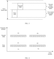
- FIG. 3 is a schematic diagram of the initial downlink BWPs of the first-type terminal device and the second-type terminal device.
- the network device configures a first BWP in first bandwidth for the first-type terminal device, and configures a second BWP in the first bandwidth for the second-type terminal device.
- Bandwidth of the second BWP may be less than or equal to bandwidth of the first BWP.
- the first-type terminal device may receive a message (also referred to as information or a signal) from the network device in the first BWP.
- the second-type terminal device has a reduced bandwidth capability.
- the second-type terminal device may receive, in the second BWP, information sent by the network device in the second BWP. Certainly, the second-type terminal device may further receive the message from the network device in the first BWP.
- the network device sends an SSB in the first BWP.
- the second-type terminal device needs to switch from the second BWP to the first BWP to receive the SSB. Because the second-type terminal device performs switching between the BWPs, a parameter, for example, bandwidth, of a radio frequency chain of the second-type terminal device needs to be adaptively adjusted, causing additional power consumption and processing complexity. Therefore, it is proposed that the network device may also broadcast an SSB in the second BWP.
- the second-type terminal device may receive the SSB in the second BWP, to reduce a quantity of BWP switching times and reduce power consumption. As shown in FIG. 3 , the network device sends a first SSB in the first BWP, and sends a second SSB in the second BWP.
- That the network device sends a second SSB in the second BWP is equivalent to that more SSBs are additionally introduced within a bandwidth range of the first BWP and the second BWP.
- a PSD of the SSB is usually higher than a PSD of another channel (or signal). If the additional SSB is introduced to the second BWP, a PSD of another channel (or signal) on a time-frequency resource in which the second BWP is located decreases. As a result, transmission performance of the another channel (or signal) deteriorates.
- the additional SSB is introduced to the second BWP, transmission performance of another downlink physical channel or reference signal, for example, a PDSCH, a PDCCH, or a CSI-RS, on the time-frequency resource in which the second BWP is located deteriorates.
- another downlink physical channel or reference signal for example, a PDSCH, a PDCCH, or a CSI-RS
- an embodiment of this application provides an SSB transmission scheme.
- a network device may independently configure an initial downlink BWP for each of a first-type terminal device and a second-type terminal device, and send an SSB in each of the independently configured initial downlink BWPs.
- the network device configures a first BWP for the first-type terminal device, and configures a second BWP for the second-type terminal device.
- the network device may send a first SSB in the first BWP, and send a second SSB in the second BWP.
- the first-type terminal device may receive the first SSB in the first BWP.
- the second-type terminal device may receive the second SSB in the second BWP without switching from the second BWP to the first BWP, to reduce a quantity of BWP switching times and a quantity of frequency tuning times of the second-type terminal device. This reduces power consumption of the second-type terminal device.
- the network device may configure transmit power of the second SSB to be the same as transmit power of the first SSB, or may configure the transmit power of the second SSB to be different from the transmit power of the first SSB. For example, the network device may configure the transmit power of the second SSB to be lower than the transmit power of the first SSB. Because the transmit power of the second SSB is lower than the transmit power of the first SSB, impact of additional introduction of the second SSB on transmission performance of another channel or signal within a carrier bandwidth range can be reduced as much as possible.
- a current related configuration of the first SSB for example, a configuration of a time-frequency resource of the first SSB or a configuration of the transmit power of the first SSB, may still be used.
- related information for example, a time-frequency resource or the transmit power, of the second SSB, may be reconfigured.
- the transmit power of the SSB may be transmit power of one or more of an SSS, a PSS, and a PBCH that are included in the SSB, and a DMRS used for the PBCH.
- the transmit power of the SSB may be the transmit power of the SSS in the SSB, for example, may be average power on each resource element (resource element, RE) carrying the SSS.
- the transmit power of the SSB may be the transmit power of the PSS in the SSB, for example, may be average power of each RE carrying the PSS. Examples are not listed herein one by one.
- That the transmit power of the first SSB is different from the transmit power of the second SSB may be that transmit power of one or more of an SSS, a PSS, and a PBCH that are included in each of the first SSB and the second SSB, and a DMRS used for the PBCH is different.
- that the transmit power of the first SSB is different from the transmit power of the second SSB may be that the transmit power of the SSS included in the first SSB is different from the transmit power of the SSB included in the second SSB.
- the transmit power of the PSSs or the PBCHs that are included in the first SSB and the second SSB, or the DMRSs used for the PBCHs may be the same or may be different.
- that the transmit power of the first SSB is different from the transmit power of the second SSB may be that the transmit power of the SSS included in the first SSB is different from the transmit power of the SSB included in the second SSB, and the transmit power of the PSSs or the PBCHs that are included in the first SSB and the second SSB, or the DMRSs used for the PBCHs is different.
- the terminal device may have different service requirements in different periods of time. For example, a service transmission rate requirement of the terminal device is high in a first time unit, and a service transmission rate requirement of the terminal device is low in a second time unit. Therefore, in this embodiment of this application, the transmit power of the first SSB is allowed to be different in different time units. For example, transmit power of the first SSB in the first time unit is first transmit power, and transmit power of the first SSB in the second time unit is second transmit power. The first transmit power is different from the second transmit power.
- the network device may adjust the transmit power of the first SSB based on a service requirement of the first-type terminal device, so that the transmit power of the first SSB adapts to an actual service requirement of the first-type terminal device, to increase a service transmission rate of the first-type terminal device.
- the transmit power of the second SSB is also allowed to be different in different time units. In this way, the network device may adjust the transmit power of the second SSB based on a service requirement of the second-type terminal device, so that the transmit power of the second SSB adapts to an actual service requirement of the second-type terminal device, to increase a service transmission rate of the second-type terminal device.
- the transmit power of the first SSB is allowed to be different from the transmit power of the second SSB in a same time unit.
- transmit power of the second SSB is lower than transmit power of the first SSB in a time unit, to minimize impact on transmission performance of another channel or signal in the time unit.
- the network device may flexibly adjust the transmit power of the first SSB and the transmit power of the second SSB based on an actual requirement, to improve transmission performance of the terminal device as much as possible, and reduce the impact on the transmission performance of the another channel or signal as much as possible.
- FIG. 4 shows transmit power of the first SSB and the second SSB in two time units.
- the two time units are T1 and T2.
- the transmit power of the first SSB in T1 is P1
- the transmit power of the first SSB in T2 is P2.
- the transmit power of the second SSB in T1 is P3, and the transmit power of the second SSB in T2 is P4.
- P1 may be different from P3, and P2 may be different from P4.
- the transmit power of the first SSB is different from that of the second SSB in the same time unit.
- the network device may adjust the transmit power of the first SSB based on the service requirement of the first-type terminal device.
- the first-type terminal device requires, in T2, a service data transmission rate higher than that in T1.
- the network device may increase the transmit power of the first SSB, in other words, P2 is greater than P1.
- the first-type terminal device requires, in T2, a service data transmission rate lower than that in T1.
- the network device may reduce the transmit power of the second SSB, in other words, P4 is less than P3.
- the network device adjusts both the transmit power of the first SSB and the transmit power of the second SSB. It is inevitable that the transmit power of the first SSB is always higher than the transmit power of the second SSB in a same time unit. As a result, transmission performance of a terminal device receiving the second SSB, namely, the second-type terminal device, is poor. Therefore, in this embodiment of this application, it may be specified or configured that a sum of the transmit power of the first SSB and the transmit power of the second SSB remains unchanged. In other words, total transmit power of the first SSB and the second SSB remains unchanged.
- a sum of the transmit power of the first SSB and the transmit power of the second SSB in the first time unit is P5
- a sum of the transmit power of the first SSB and the transmit power of the second SSB in the second time unit is also P5.
- the network device may adjust the transmit power of the first SSB or the transmit power of the second SSB based on that the total transmit power of the first SSB and the second SSB remains unchanged, to avoid, as much as possible, a case in which transmit power of one of the first SSB and the second SSB is always higher than transmit power of the other SSB, so as to improve transmission performance of a terminal device that receives an SSB with the lower transmit power as much as possible.
- this also avoids a case in which transmit power of another channel or signal is greatly reduced because both the power of the first SSB and the power of the second SSB are high, and transmission performance of the another channel or signal deteriorates due to introduction of the second SSB.
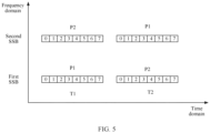
- FIG. 5 shows transmit power of the first SSB and the second SSB in two time units.
- a difference between FIG. 5 and FIG. 4 lies in that the transmit power of the second SSB in T1 is P2, and the transmit power of the second SSB in T2 is P1.
- the sum of the transmit power of the first SSB and the transmit power of the second SSB in T1 is P1+P2
- the sum of the transmit power of the first SSB and the transmit power of the second SSB in T2 is P2+P1.
- the sum of the transmit power of the first SSB and the transmit power of the second SSB remains unchanged in a time unit. Therefore, this can avoid that the transmit power of the first SSB is always higher than the transmit power of the second SSB, to improve the transmission performance of the second-type terminal device as much as possible.
- a time domain resource occupied by the first SSB is the same as a time domain resource occupied by the second SSB.
- transmit power on a time-frequency resource in which the time domain resource is located includes at least the transmit power of the first SSB and the transmit power of the second SSB.
- the transmit power on the time-frequency resource is high.
- a PSD of a remaining channel or signal on the time-frequency resource is lower.
- transmission performance of the remaining channel or signal on the time-frequency resource is more affected. Therefore, in this embodiment of this application, the time domain resource occupied by the first SSB may be configured to be different from the time domain resource occupied by the second SSB.
- FIG. 6 is a schematic diagram of time domain resources occupied by the first SSB and the second SSB. It can be learned from FIG. 6 that the first SSB and the second SSB each occupy different time domain resources. In this case, the sum of the transmit power of the first SSB and the transmit power of the second SSB is always less than P1+P2 in T2. In this case, the transmission performance of the another channel or signal is less affected.
- the terminal device when the first SSB and the second SSB cannot be both included in bandwidth of the terminal device, if time domain positions of the first SSB and the second SSB are the same, the terminal device cannot receive the first SSB and the second SSB at the same time.
- the time domain resource occupied by the first SSB is different from the time domain resource occupied by the second SSB. Therefore, the terminal device may receive the first SSB and the second SSB in a time division manner.
- the first SSB and the second SSB can be separately received and measured at different frequencies. In this way, the terminal device can measure more SSBs in a same time unit without increasing SSB time-frequency resource overheads.
- the terminal device measures more SSBs in a same time unit, more accurate channel information or channel quality information can be obtained by measuring the SSBs. This helps improve the transmission performance of the terminal device. It may also be understood that compared with a case in which the time domain resource occupied by the first SSB is the same as the time domain resource occupied by the second SSB, when the time domain resource occupied by the first SSB is different from the time domain resource occupied by the second SSB, the SSB time-frequency resource overheads may be reduced in a case in which same measurement performance of the terminal device is obtained.
- the network device may configure the time domain resources occupied by the first SSB and the second SSB based on one or more of the following implementation forms. This is flexible.
- Implementation form 1 A time domain position of a synchronization signal burst of the first SSB is different from a time domain position of a synchronization signal burst of the second SSB.
- the time domain position of the burst of the first SSB may be designed to be different from the time domain position of the burst of the second SSB.
- the burst of the first SSB and the burst of the second SSB are located in a same system frame X.
- the burst of the first SSB is located in the first half-frame of the system frame X
- the burst of the second SSB is located in the second half-frame of the system frame X.
- the burst of the first SSB and the burst of the second SSB are located in the first half-frames or the second half-frames of different system frames.
- the burst of the first SSB is located in the first half of the system frame X
- the burst of the second SSB is located in the first half of a system frame Y where X is not equal to Y.
- Implementation form 2 A sending periodicity of the first SSB is different from a sending periodicity of the second SSB.
- the sending periodicity of the first SSB may be designed to be different from the sending periodicity of the second SSB.
- the sending periodicity of the first SSB is 20 ms
- the sending periodicity of the second SSB is 40 ms.
- the first-type terminal device and the second-type terminal device have different service types, service requirements, energy saving requirements, and the like.
- the sending periodicity of the first SSB is allowed to be different from the sending periodicity of the second SSB, in other words, the sending periodicity of the first SSB may not be associated with the sending periodicity of the second SSB. Therefore, the network device may separately adjust the sending periodicity of the first SSB and the sending periodicity of the second SSB. For example, the network device may adjust the sending periodicity of the first SSB based on the service requirement, the energy saving requirement, or the like of the first-type terminal device, to meet the energy saving requirement of the first-type terminal device.
- the network device may also adjust the sending periodicity of the second SSB based on the service requirement, the energy saving requirement, or the like of the second-type terminal device, to meet the energy saving requirement of the second-type terminal device. For example, compared with the second-type terminal device, the first-type terminal device has a higher requirement on power consumption, and focuses more on energy saving. In this case, the sending periodicity of the first SSB is larger than the sending periodicity of the second SSB, to meet a power consumption requirement of the second-type terminal device.
- a quantity of SSB beams in the synchronization signal burst of the first SSB is different from a quantity of SSB beams in the synchronization signal burst of the second SSB.
- a quantity of SSBs sent in the burst of the first SSB is M
- a quantity of SSBs sent in the burst of the second SSB is N. Both M and N are positive integers, and M is not equal to N.
- coverage performance of the first-type terminal device is also different from that of the second-type terminal device because the first-type terminal device and the second-type terminal device have different bandwidth capabilities, antenna quantities, and the like.
- the network device separately adjusts the quantity of SSBs sent in the burst of the first SSB and the quantity of SSBs sent in the burst of the second SSB. For example, the network device may adjust the quantity of SSBs sent in the burst of the first SSB based on the coverage performance of the first-type terminal device. Similarly, the network device may also adjust the quantity of SSBs sent in the burst of the second SSB based on the coverage performance of the second-type terminal device, to improve the transmission performance of the second-type terminal device.
- the time domain position of the first SSB or the time domain position of the second SSB may be indicated by the network device.
- the network device sends resource indication information to the second-type terminal device.
- the resource indication information indicates the time domain position of the second SSB.
- the resource indication information includes a number of a system frame, a half-frame, or the like in which the second SSB is located.
- the second-type terminal device receives the resource indication information, and may determine that the system frame number or the half-frame number included in the resource indication information is the time domain position of the second SSB.
- the resource indication information includes a time offset between the time domain position of the second SSB and the time domain position of the first SSB.
- the second-type terminal device receives the resource indication information, and may determine the time domain position of the second SSB based on the time offset included in the resource indication information and the time domain position of the first SSB.
- the network device may reuse an SSB measure timing configuration, for example, an occasion for measuring the SSB by the terminal device, to indicate the time domain position of the SSB.
- the network device may send a second measure timing configuration (SSB measure timing configuration, SSB-MTC) to the second-type terminal device.
- SSB measure timing configuration SSB measure timing configuration, SSB-MTC
- the second SSB-MTC is used to configure a measure timing configuration of the second SSB, for example, an occasion for measuring the second SSB by the second-type terminal device.
- the second SSB-MTC may include a measurement periodicity, duration, and the like of the second SSB. It may be understood that the network device may also send a first SSB-MTC to the first-type terminal device and/or a second terminal device, to indicate the time domain position of the first SSB. The second SSB-MTC may separately configure the time domain position of the second SSB, or may indicate the time domain position of the second SSB by configuring an offset from the time domain position of the first SSB.
- the resource indication information may be carried in one or more types of signaling, for example, a system information block (system information block, SIB), radio resource control (radio resource control, RRC) signaling, a media access control control element (media access control control control element, MAC CE), or downlink control information (downlink control information, DCI).
- SIB system information block
- RRC radio resource control
- media access control control element media access control control control element
- DCI downlink control information
- the network device may independently configure the first BWP for the first-type terminal device, configure the second BWP for the second-type terminal device, send the first SSB in the first BWP, and send the second SSB in the second BWP.
- the new second SSB is introduced.
- the first-type terminal device may receive the first SSB in the first BWP.
- the second-type terminal device may receive the first SSB in the first BWP, and may also receive the second SSB in the second BWP.
- the terminal device may perform one or more of RRM measurement, time and frequency synchronization measurement, channel quality measurement, QCL measurement, and the like based on the received first SSB and/or second SSB. For example, an attribute of a channel carrying other information or a signal is determined based on the received first SSB and/or second SSB.
- FIG. 7 shows a procedure of an SSB sending and receiving method according to an embodiment of this application.
- the method may be performed by two communication apparatuses.
- the two communication apparatuses are, for example, a first communication apparatus and a second communication apparatus.
- the first communication apparatus may be a network device or a communication apparatus that can support the network device in implementing a function required by the method.
- the first communication apparatus may be a terminal device or a communication apparatus that can support the terminal device in implementing a function required by the method, or certainly may be another communication apparatus, for example, a chip system.
- the second communication apparatus may be a network device or a communication apparatus that can support the network device in implementing a function required by the method.
- the second communication apparatus may be a terminal device or a communication apparatus that can support the terminal device in implementing a function required by the method, or certainly may be another communication apparatus, for example, a chip system.
- implementations of both the first communication apparatus and the second communication apparatus are not limited.
- the first communication apparatus may be a network device, and the second communication apparatus is a terminal device; both the first communication apparatus and the second communication apparatus are network devices; both the first communication apparatus and the second communication apparatus are terminal devices; or the first communication apparatus is a network device, and the second communication apparatus is a communication apparatus that can support the terminal device in implementing a function required by the method.
- the network device is, for example, a base station.
- the first communication apparatus is the network device and the second communication apparatus is the terminal device.
- the network device described below may be the network device in the network architecture shown in FIG. 1
- the terminal device described below may be a first-type terminal device or a second-type terminal device.
- the network device sends a first SSB in a first BWP.
- the first-type terminal device receives the first SSB in the first BWP.
- the network device sends a second SSB in a second BWP.
- the second-type terminal device receives the second SSB in the second BWP.
- the network device is allowed to send the first SSB in the first BWP and send the second SSB in the second BWP.
- the network device may determine some sending parameters of the first SSB, for example, transmit power or a time-frequency resource.
- the network device may determine some sending parameters of the second SSB, for example, transmit power or a time-frequency resource.
- the network device may configure the transmit power of the second SSB to be lower than the transmit power of the first SSB.
- the network device may adjust the transmit power of the first SSB based on the actual service requirement of the first-type terminal device (or the second-type terminal device).
- the network device may flexibly adjust the transmit power of the first SSB and the transmit power of the second SSB, to improve transmission performance of the first-type terminal device and the second-type terminal device as much as possible, and reduce impact on transmission performance of the another channel or signal.
- the network device may flexibly adjust a time domain resource occupied by the first SSB and a time domain resource occupied by the second SSB, to further reduce the impact on the transmission performance of the another channel or signal on the time-frequency resource, and improve an RRM measurement result, so as to improve transmission performance of the terminal device.
- sending of the first SSB by the network device in the first BWP and sending of the second SSB by the network device in the second BWP are performed independently.
- a sequence of S701 and S702 is not limited.
- the first-type terminal device may receive the first SSB in the first BWP.
- the second-type terminal device may receive the first SSB in the first BWP, and may also receive the second SSB in the second BWP. It should be understood that the second-type terminal device may obtain the second SSB in the second BWP, that is, do not need to always switch to the first BWP to obtain the SSB.
- a quantity of BWP switching times or a quantity of radio frequency retuning times can be reduced, to reduce energy consumption and complexity of the second-type terminal device, reduce data transmission interruption caused by BWP switching or radio frequency retuning, and improve transmission efficiency of the second-type terminal device.
- the second-type terminal device performs RRM measurement based on the first SSB and/or the second SSB.
- the network device is allowed to send the first SSB in the first BWP, and send the second SSB in the second BWP.
- the second-type terminal device may receive the first SSB in the first BWP, and may also receive the second SSB in the second BWP. It should be understood that the second-type terminal device receives the first SSB, and may perform the RRM measurement based on the first SSB.
- the second-type terminal device receives the second SSB, and may perform the RRM measurement based on the second SSB.
- the second-type terminal device may perform the RRM measurement based on the first SSB and/or the second SSB.
- an SSB used for the RRM measurement is an SSB in a BWP in which a paging resource is located.
- a configuration of the paging resource of the second-type terminal device is not limited in this embodiment of this application.
- all paging resources of the second-type terminal device may be configured within a first BWP range or within a second BWP range.
- a part of all the paging resources of the second-type terminal device are configured within the first BWP range, and the other part of the paging resources are configured within the second BWP range. If all the paging resources of the second-type terminal device are within the second BWP range, the second-type terminal device performs the RRM measurement based on the second SSB.
- the second-type terminal device performs the RRM measurement based on the first SSB. If a part of the paging resources of the second-type terminal device are configured in the first BWP, and the other part of the paging resources are configured in the second BWP, the second-type terminal device whose paging resource is in the first BWP performs the RRM measurement based on the first SSB, and the second-type terminal device whose paging resource is in the second BWP performs the RRM measurement based on the second SSB. In this way, it can be ensured that the second-type terminal device performs the RRM measurement in a process of monitoring paging, and does not need to perform BWP switching, to reduce power consumption of the second-type terminal device.
- the second-type terminal device performs the RRM measurement based on both the first SSB and the second SSB.
- the second-type terminal device may separately measure the first SSB and the second SSB on the different time domain resources, and a measurement result is jointly determined by measurement results of the first SSB and the second SSB.
- the second-type terminal device in a limited coverage area performs measurement based on the first SSB and the second SSB. This can improve measurement performance of the terminal device, to improve the transmission performance of the terminal device.
- that the second-type terminal device performs the RRM measurement based on the first SSB and the second SSB may be predefined or indicated by the network device by using signaling.
- the terminal device starts joint measurement of the first SSB and the second SSB.
- the threshold may be indicated by the network device by using signaling, predefined in a protocol, or determined by the terminal device based on an algorithm.
- the second-type terminal device performs the RRM measurement based only on the first SSB.
- the network device may indicate the second-type terminal device to perform the RRM measurement based only on the first SSB.
- the transmit power, a beam, and the like of the second SSB are different from those of the first SSB.
- the transmit power of the second SSB is lower than the transmit power of the first SSB. If the second-type terminal performs the measurement based on the second SSB, an obtained measurement result (for example, a received power value) is low.
- the second-type terminal device may perform a process such as cell selection/reselection and switching based on the measurement result, and a selected cell may not be preferred.
- that the second-type terminal device performs the RRM measurement based only on the first SSB is predefined or indicated by the network device by using the signaling, to improve the measurement result as much as possible, so that a cell selected by the terminal device based on the measurement result is preferred.
- the second-type terminal device After determining an SSB used for the RRM measurement, the second-type terminal device performs the RRM measurement based on the determined SSB. It may be understood that, if transmit power of the SSB is low, accuracy of a measurement result obtained based on the SSB is low. Therefore, accuracy of determining cell coverage is also low. Therefore, in this embodiment of this application, it is specified that only an SSB whose transmit power is higher than a preset threshold is used for the RRM measurement. This can improve the accuracy of determining the cell coverage.
- the SSB used for the RRM measurement is the second SSB.
- the second-type terminal device may perform the RRM measurement based on the second SSB whose transmit power is higher than the preset threshold. In other words, a second SSB whose transmit power is lower than the preset threshold is not used to perform the RRM measurement, to improve accuracy of the RRM measurement as much as possible.
- the second-type terminal device may alternatively perform the RRM measurement based on all received second SSBs.
- these second SSBs are still used to perform the RRM measurement. Because the accuracy of the RRM measurement result obtained based on the second SSB whose transmit power is lower than the preset threshold is low, the obtained RRM measurement result may be corrected in this embodiment of this application.
- an actual measurement result obtained based on the second SSB is adjusted, and an adjusted measurement result is used as a final RRM measurement result.
- the RRM measurement result is a sum of the measurement result of the second SSB and an offset
- the offset is related to the transmit power of the first SSB and the transmit power of the second SSB.
- the offset is a difference between transmit power P1 of the first SSB and transmit power P2 of the second SSB.
- BWPs used by the second-type terminal device to initiate a random access process are also different.
- the second-type terminal device may send the random access process in the first BWP and/or the second BWP, for example, transmission of Msg2, Msg4, and the like in the random access process in the first BWP and/or the second BWP.
- the first BWP may be used for transmission of a message other than a message in the random access process, for example, transmission of a system message or a paging message.
- the paging resources of the second-type terminal device may be configured in two BWPs.
- a part of the paging resources of the second-type terminal device are configured in the first BWP
- the other part of the paging resources are configured in the second BWP.
- a BWP used for transmission of the message in the random access process is consistent with a BWP used for transmission of the paging message.
- the network device sends the paging message in the first BWP
- the network device sends Msg2 or Msg4 to the second-type terminal device in the first BWP.
- the network device sends Msg2 or Msg4 to the second-type terminal device in the second BWP.
- S703 is described by using only the RRM measurement as an example.
- the first SSB and/or the second SSB may be further used for time and frequency synchronization measurement, path loss measurement, beam management, and the like. Methods for receiving and measuring the second SSB and/or the second SSB in S703 are all applicable to the process.
- the network device may further send other information, for example, one or more of the paging message, the system message, a random access response message, or a contention resolution message.
- the paging message, the system message, the random access response message, and the contention resolution message are collectively referred to as first information below.
- the first information usually has a QCL relationship with the SSB.
- the second BWP namely, the first SSB and the second SSB, is introduced.
- the terminal device may infer, based on the first SSB or the second SSB, some characteristics of a channel for sending the first information.
- the first SSB or the second SSB may have the QCL relationship with the first information.
- the first information has the QCL relationship with the first SSB (or the second SSB) means that a DMRS antenna port of a PDSCH carrying the first information has the QCL relationship with the first SSB (or the second SSB), or a DMRS antenna port of a PDCCH for scheduling the first information has the QCL relationship with the first SSB (or the second SSB).
- the SSB having the QCL relationship with the first information also varies.
- the DMRS antenna port of the PDSCH that carries the first information has the QCL relationship with the first SSB or the second SSB, or the DMRS antenna port of the PDCCH for scheduling the first information has the QCL relationship with the first SSB or the second SSB.
- a specific SSB having the QCL relationship with the channel for sending the first information is specified, to ensure transmission performance of the first information.
- the first information is the system message or the paging message.
- the BWP that carries the first information is the first BWP
- the DMRS antenna port of the PDSCH that carries the first information has the QCL relationship with the first SSB, and/or the DMRS antenna port of the PDCCH for scheduling the first information has the QCL relationship with the first SSB.
- the BWP that carries the first information is the second BWP
- the DMRS antenna port of the PDSCH that carries the first information has the QCL relationship with the second SSB
- the DMRS antenna port of the PDCCH for scheduling the first information has the QCL relationship with the second SSB.
- the first information is a random access response message or a contention resolution message
- the first BWP and the second BWP respectively correspond to different random access channel occasions (random access channel occasions, ROs).
- the BWP that carries the first information is the first BWP
- the DMRS antenna port of the PDSCH that carries the first information has the QCL relationship with the first SSB
- the DMRS antenna port of the PDCCH for scheduling the first information has the QCL relationship with the first SSB.
- the DMRS antenna port of the PDSCH that carries the first information has the QCL relationship with the second SSB, and/or the DMRS antenna port of the PDCCH for scheduling the first information has the QCL relationship with the second SSB.
- the first information is a random access response message or a contention resolution message, but the first BWP and the second BWP share a first RO.
- the network device configures a mapping relationship between the first SSB and the first RO, the DMRS antenna port of the PDSCH that carries the first information has the QCL relationship with the first SSB, and/or the DMRS antenna port of the PDCCH for scheduling the first information has the QCL relationship with the first SSB.
- the network device configures the mapping relationship between the first SSB and the first RO and a mapping relationship between the second SSB and the first RO, and the BWP that carries the first information is the first BWP, the DMRS antenna port of the PDSCH that carries the first information has the QCL relationship with the first SSB, and/or the DMRS antenna port of the PDCCH for scheduling the first information has the QCL relationship with the first SSB.
- the network device configures the mapping relationship between the first SSB and the first RO and the mapping relationship between the second SSB and the first RO, and the BWP that carries the first information is the second BWP, the DMRS antenna port of the PDSCH that carries the first information has the QCL relationship with the second SSB, and/or the DMRS antenna port of the PDCCH for scheduling the first information has the QCL relationship with the second SSB.
- the network device sends indication information to the second-type terminal device.
- the second-type terminal device receives the indication information from the network device.
- the indication information indicates the transmit power of the second SSB.
- the second-type terminal device needs to obtain some pieces of information by using the transmit power of the second SSB.
- the second-type terminal device may determine a path loss of signal transmission based on the transmit power of the second SSB and received power of the second SSB, and adjust transmit power of a to-be-sent signal based on the path loss, to improve signal transmission reliability. For example, transmit power of a random access message 1, transmit power of a random access message 3, and transmit power of a channel or signal, for example, a PUCCH, that carries a HARQ feedback of a random access message 4 may be determined. Therefore, in this embodiment of this application, the network device may notify the transmit power of the second SSB to the second-type terminal device.
- the network device may send the indication information to the second-type terminal device.
- the indication information may indicate the transmit power of the second SSB.
- the power indication information may be carried in one or more types of signaling such as a SIB, RRC signaling, a MAC CE, or DCI.
- the indication information may directly indicate the transmit power of the second SSB, or may indirectly indicate the transmit power of the second SSB.
- the indication information may include the transmit power of the second SSB.
- the second-type terminal device receives the indication information, and may obtain the transmit power of the second SSB from the indication information. This is simple.
- the indication information includes a power offset.
- the power offset is a difference between the transmit power of the second SSB and the transmit power of the first SSB.
- the second-type terminal device may determine the transmit power of the second SSB based on the power offset and the transmit power of the first SSB.
- S704 is not a mandatory step, and therefore is illustrated by dashed lines in FIG. 7 . If S704 is performed, S704 is not related to a sequence of S701 and S703. To be specific, S704 may be performed after S701, or may be performed after S703.
- the second SSB is additionally introduced to the second BWP configured for the second-type terminal device, for example, how to send the second SSB, namely, some conditions needing to be met for sending the second SSB, for example, a condition that needs to be met by transmit power or a time-frequency resource position of the second SSB; or for another example, how the second-type terminal performs the RRM measurement.
- the network device may configure the second BWP for the second-type terminal device, may configure the first BWP for the second-type terminal device, or may configure the first BWP and the second BWP for the second-type terminal device.
- the following describes how the network device configures the BWP for the second-type terminal device.
- the network device may indicate, by using second indication information, the BWP configured for the second-type terminal device.
- the second indication information may be carried in one or more of a SIB, RRC signaling, a MAC CE, DCI, or the like.
- the second indication information is a bitmap whose length is 2 bits, and each bit corresponds to one BWP.
- the 1 st bit in the 2 bits corresponds to the first BWP
- the 2 nd bit in the 2 bits corresponds to the second BWP. If a value of a bit corresponding to a BWP is a first value, the BWP is a BWP configured for the second-type terminal device or the second-type terminal device may use the BWP.
- a value of a bit corresponding to a BWP is a second value
- the BWP is not a BWP configured for the second-type terminal device or the second-type terminal device cannot use the BWP
- the first value is 0, the second value is 1; or when the first value is 1, the second value is 0.
- the first value is 1, and the second value is 0.
- content indicated by the 2-bit bitmap may be shown in Table 1.
- a quantity of BWPs configured by the network device for the second-type terminal device is not limited.
- the network device may configure more BWPs for the second-type terminal device.
- the network device may further configure a third BWP, even a fourth BWP, and the like for the second-type terminal device.
- the network device configures more BWPs for the second-type terminal device.
- a quantity of bits occupied by the second indication information may vary with a quantity of the BWPs. For example, if there are Y BWPs, the second indication information may be a bitmap whose length is Y bits.
- the first BWP and the second BWP exist. It may be agreed that a BWP other than the first BWP is a BWP available to the second-type terminal device by default.
- the network device may indicate, by using the second indication information, whether the first BWP is available. For example, if the second indication information indicates that the first BWP is available, the network device configures the first BWP and the second BWP for the second-type terminal device. For example, if the second indication information indicates that the first BWP is unavailable, the network device configures the second BWP for the second-type terminal device.
- the second indication information may occupy 1 bit. If a value of the 1 bit is the first value, it indicates that the first BWP is available. Correspondingly, if the value of the 1 bit is the second value, it indicates that the first BWP is unavailable.
- the network device may alternatively configure, for the second-type terminal device by using the second indication information, a BWP used for transmission on each channel.
- the network device may configure a BWP for a paging message, SIB1, a random access message 2, a random access message 4, other system information (other system information, OSI), or the like.
- SIB1 a paging message
- a random access message 2 a random access message 4
- other system information other system information (other system information, OSI), or the like.
- OSI system information
- the network device may indicate, by using the second indication information occupying 2 bits, whether the first BWP and the second BWP are available. Assuming that there are X channels, the second indication information may occupy 2X bits, and each channel corresponds to 2 bits in the 2X bits.
- the 2X bits are in one-to-one correspondence with the X channels.
- the first BWP and the second BWP exist. It may be agreed that a BWP other than the first BWP is a BWP available to the second-type terminal device by default. In this case, for each channel, the network device may indicate, by using 1-bit second indication information, whether the first BWP is available.
- the network device may independently configure an initial downlink BWP for each of the first-type terminal device and the second-type terminal device, and send the SSB in each of the independently configured initial downlink BWPs.
- the network device configures the first BWP for the first-type terminal device, and configures the second BWP for the second-type terminal device.
- the network device may send the first SSB in the first BWP, and send the second SSB in the second BWP.
- the first-type terminal device may receive the first SSB in the first BWP.
- the second-type terminal device may receive the second SSB in the second BWP without always switching from the second BWP to the first BWP, to reduce a quantity of BWP switching times and a quantity of frequency tuning times of the second-type terminal device. This reduces power consumption of the second-type terminal device.
- the network device may configure the transmit power of the second SSB to be lower than the transmit power of the first SSB. Because the transmit power of the second SSB is lower than the transmit power of the first SSB, impact of additional introduction of the second SSB on transmission performance of another channel or signal within a carrier bandwidth range can be reduced as much as possible.
- the method provided in embodiments of this application is described from a perspective of interaction between the network device and the terminal device.
- the steps performed by the network device may alternatively be separately implemented by different communication apparatuses.
- a first apparatus is configured to determine the first SSB and the second SSB
- a second apparatus is configured to send the first SSB and the second SSB.
- the first apparatus and the second apparatus jointly complete the steps performed by the network device in embodiments of this application.
- a specific division manner is not limited in this application.
- the steps performed by the network device may be separately implemented by the DUs, the CUs, and the RUs.
- the terminal device and the network device may include a hardware structure and/or a software module, and implement the foregoing functions in a form of hardware structure, software module, or a combination of the hardware structure and the software module. Whether a function in the foregoing functions is performed by the hardware structure, the software module, or the combination of the hardware structure and the software module depends on a specific application and a design constraint of the technical solutions.
- an embodiment of this application provides a communication apparatus.
- the following describes, with reference to the accompanying drawings, the communication apparatus configured to implement the foregoing method in embodiments of this application.
- FIG. 8 is a schematic block diagram of a communication apparatus 800 according to an embodiment of this application.
- the communication apparatus 800 may be the network device in FIG. 1 , and is configured to implement the method for the network device in the foregoing method embodiment.
- the communication apparatus 800 includes one or more processors 801.
- the processor 801 may also be referred to as a processing unit, and may implement a specific control function.
- the processor 801 may be a general-purpose processor, a dedicated processor, or the like.
- the processor 801 includes a baseband processor, a central processing unit, an application processor, a modem processor, a graphics processor, an image signal processor, a digital signal processor, a video codec processor, a controller, a memory, and/or a neural network processor.
- the baseband processor may be configured to process a communication protocol and communication data.
- the central processing unit may be configured to: control the communication apparatus 800, execute a software program, and/or process data.
- Different processors may be independent components, or may be integrated into one or more processors, for example, integrated into one or more application-specific integrated circuits.
- the communication apparatus 800 includes one or more memories 802, configured to store instructions 804.
- the instructions may be run on the processor, to enable the communication apparatus 800 to perform the method described in the foregoing method embodiment.
- the memory 802 may further store the data.
- the processor and the memory may be separately disposed, or may be integrated together.
- the communication apparatus 800 may include instructions 803 (sometimes may also be referred to as code or a program).
- the instruction 803 may be run on the processor, to enable the communication apparatus 800 to perform the method described in the foregoing embodiment.
- the processor 801 may store the data.
- the communication apparatus 800 may further include a transceiver 805 and an antenna 806.
- the transceiver 805 may be referred to as a transceiver unit, a transceiver machine, a transceiver circuit, a transceiver, an input/output interface, or the like, and is configured to implement receiving and sending functions of the communication apparatus 800 through the antenna 806.
- the communication apparatus 800 may further include one or more of the following parts: a wireless communication module, an audio module, an external memory interface, an internal memory, a universal serial bus (universal serial bus, USB) interface, a power management module, an antenna, a loudspeaker, a microphone, an input/output module, a sensor module, a motor, a camera, a display, or the like. It may be understood that, in some embodiments, the communication apparatus 800 may include more or fewer parts, some parts may be integrated, or some parts may be split. These parts may be implemented by hardware, software, or a combination of the software and the hardware.
- the processor 801 and the transceiver 805 described in this application may be implemented on an integrated circuit (integrated circuit, IC), an analog IC, a radio frequency integrated circuit (radio frequency identification, RFID), a hybrid signal IC, an application-specific integrated circuit (application-specific integrated circuit, ASIC), a printed circuit board (printed circuit board, PCB), an electronic device, or the like.
- the communication apparatus described in this specification may be an independent device (for example, an independent integrated circuit or a mobile phone), or may be a part of a large device (for example, a module that may be embedded in another device). For details, refer to the foregoing descriptions about the terminal device and the network device. Details are not described herein again.
- the terminal device (for ease of description, referred to as a UE) may be used in the foregoing embodiments.
- the terminal device includes a corresponding means (means), a unit, and/or a circuit used to implement a function of the UE in the embodiment shown in FIG. 7 .
- the terminal device includes a transceiver module, configured to support the terminal device in implementing receiving and sending functions; and a processing module, configured to support the terminal device in processing a signal.
- FIG. 9 is a schematic diagram of a structure of a terminal device according to an embodiment of this application.
- the terminal device 900 shown in FIG. 9 is applicable to the system shown in FIG. 1 .
- FIG. 9 shows only main parts of the terminal device 900.
- the terminal device 900 includes a processor, a memory, a control circuit, an antenna, and an input/output apparatus.
- the processor is mainly configured to: process a communication protocol and communication data, control the entire terminal device 900, execute a software program, and process data of the software program.
- the memory is mainly configured to store the software program and the data.
- the control circuit is mainly configured to: perform conversion between a baseband signal and a radio frequency signal, and process the radio frequency signal.
- the antenna is mainly configured to receive and send the radio frequency signal in a form of electromagnetic wave.
- the input/output apparatus for example, a touchscreen, a display, a microphone, or a keyboard, is mainly configured to: receive data input by a user and output data to the user.
- the terminal device 900 is a mobile phone.
- the processor may read a software program in a storage unit, interpret and execute instructions of the software program, and process data of the software program.
- the processor performs baseband processing on the to-be-sent data, and outputs a baseband signal to the control circuit.
- the control circuit performs radio frequency processing on the baseband signal, and sends, through the antenna, a radio frequency signal in the form of electromagnetic wave.
- the control circuit receives the radio frequency signal through the antenna, converts the radio frequency signal into a baseband signal, and outputs the baseband signal to the processor.
- the processor converts the baseband signal into data and processes the data.
- FIG. 9 shows only one memory and only one processor.
- the terminal device 900 may include a plurality of processor and memories.
- the memory may also be referred to as a storage medium, a storage device, or the like. This is not limited in this embodiment of the present invention.
- the processor may include a baseband processor and a central processing unit.
- the baseband processor is mainly configured to process a communication protocol and communication data.
- the central processing unit is mainly configured to: control the entire terminal device 900, execute a software program, and process data of the software program.
- the processor in FIG. 9 integrates functions of the baseband processor and the central processing unit.
- the baseband processor and the central processing unit may alternatively be processors independent of each other, and are interconnected by using a technology such as through a bus.
- the terminal device 900 may include a plurality of baseband processors to adapt to different network standards.
- the terminal device 900 may include a plurality of central processing units to enhance a processing capability of the terminal device.
- the baseband processor may also be expressed as a baseband processing circuit or a baseband processing chip.
- the central processing unit may also be expressed as a central processing circuit or a central processing chip.
- a function of processing the communication protocol and the communication data may be built in the processor; or may be stored in a storage unit in a form of software program, and the processor executes the software program to implement a baseband processing function.
- the antenna and the control circuit that have receiving and sending functions may be considered as a transceiver unit 910 of the terminal device 900, and the processor having a processing function may be considered as a processing unit 920 of the terminal device 900.
- the terminal device 900 includes the transceiver unit 910 and the processing unit 920.
- the transceiver unit may also be referred to as a transceiver, a transceiver machine, a transceiver apparatus, or the like.
- a component that is in the transceiver unit 910 and that is configured to implement the receiving function may be considered as a receiving unit
- a component that is in the transceiver unit 910 and that is configured to implement the sending function may be considered as a sending unit.
- the transceiver unit 910 includes the receiving unit and the sending unit.
- the receiving unit may also be referred to as a receiver machine, a receiver, a receiver circuit, or the like.
- the sending unit may be referred to as a transmitter machine, a transmitter, a transmitter circuit, or the like.
- An embodiment of this application further provides a network device.
- the network device may be used in the foregoing embodiments.
- the network device includes a means (means), a unit, and/or a circuit used to implement a function of the network device in the embodiment shown in FIG. 7 .
- the network device includes a transceiver module, configured to support the terminal device in implementing receiving and sending functions; and a processing module, configured to support the network device in processing a signal. It may be understood that a first network device and a second network device are relative to one or some UEs, and functions of the first network device and the second network device are interchangeable relative to some other UEs.
- FIG. 10 is a schematic diagram of a structure of a network device according to an embodiment of this application.
- the network device 20 is applicable to the system shown in FIG. 1 .
- the network device 20 is, for example, the network device shown in FIG. 1 .
- the network device 20 may serve as a first network device that is relative to one or some UEs and that has a function of the first network device, or may serve as a second network device that is relative to one or some UEs and that has a function of the second network device.
- the network device includes a baseband apparatus 201, a radio frequency apparatus 202, and an antenna 203.
- the radio frequency apparatus 202 receives, through the antenna 203, information sent by a terminal device, and sends the information sent by the terminal device to the baseband apparatus 201 for processing.
- the baseband apparatus 201 processes the information of the terminal device, and sends processed information to the radio frequency apparatus 202.
- the radio frequency apparatus 202 processes the information of the terminal device, and sends processed information to the terminal device through the antenna 203.
- the baseband apparatus 201 includes one or more processing units 2011, a storage unit 2012, and an interface 2013.
- the processing unit 2011 is configured to support the network device in performing a function of the network device in the foregoing method embodiment.
- the storage unit 2012 is configured to store a software program and/or data.
- the interface 2013 is configured to exchange information with the radio frequency apparatus 202.
- the interface includes an interface circuit, configured to input and output information.
- the processing unit is an integrated circuit, for example, one or more ASICs, one or more DSPs, one or more FPGAs, or a combination of these types of integrated circuits. These integrated circuits may be integrated together to form a chip.
- the storage unit 2012 and the processing unit 2011 may be located on a same chip, namely, an on-chip storage element.
- the storage unit 2012 and the processing unit 2011 may be located on a chip different from that of the processing element 2011, namely, an off-chip storage element.
- the storage unit 2012 may be one memory, or may be a general term of a plurality of memories or storage elements.
- the network device may implement some or all of the steps in the foregoing method embodiments in a form of scheduling a program by using one or more processing units. For example, a corresponding function of the network device in FIG. 7 is implemented.
- the one or more processing units may support radio access technologies of a same standard, or may support radio access standards of different standards.
- the apparatus may include a transceiver unit and a processing unit.
- the transceiver unit may be an input/output circuit and/or a communication interface.
- the processing unit is an integrated processor, a microprocessor, or an integrated circuit.
- the communication system includes a network device and a terminal device, or may include a plurality of network devices and a plurality of terminal devices.
- the communication system includes a network device and a terminal device that are configured to implement related functions in FIG. 7 .
- the network device is configured to implement a function related to a network part in FIG. 7 .
- the terminal device is configured to implement a function related to the terminal device in FIG. 7 .
- An embodiment of this application further provides a computer-readable storage medium, including instructions.
- the computer When the instructions are run on a computer, the computer is enabled to perform the method performed by the network device in FIG. 7 .
- the instructions when the instructions are run on a computer, the computer is enabled to perform the method performed by the terminal device in FIG. 7 .
- An embodiment of this application further provides a computer program product, including instructions.
- the computer When the instructions are run on a computer, the computer is enabled to perform the method performed by the network device in FIG. 7 .
- the instructions when the instructions are run on a computer, the computer is enabled to perform the method performed by the terminal device in FIG. 7 .
- the chip system includes a processor, and may further include a memory, configured to implement a function of the network device or the terminal in the foregoing method, or is configured to implement functions of the network device and the terminal in the foregoing method.
- the chip system may include a chip, or may include the chip and another discrete component.
- sequence numbers of the foregoing processes do not mean execution sequences in various embodiments of this application.
- the execution sequences of the processes should be determined based on functions and internal logic of the processes, and should not be construed as any limitation on the implementation processes of embodiments of this application.
- the units described as separate parts may or may not be physically separate, and parts displayed as units may or may not be physical units, and may be located at one location, or may be distributed on a plurality of network units. Some or all of the units may be selected based on actual requirements to achieve the objectives of the solutions of the embodiments.
- the functions When the functions are implemented in a form of software functional unit and sold or used as an independent product, the functions may be stored in a computer-readable storage medium. Based on such an understanding, the technical solutions of this application essentially, or the part contributing to an existing technology, or all or some of the technical solutions may be implemented in a form of software product.
- the computer software product is stored in a storage medium, and includes several instructions for instructing a computer device (which may be a personal computer, a server, or a network device) to perform all or some of the steps of the methods described in embodiments of this application.
- the foregoing storage medium includes any medium that can store program code, for example, a USB flash drive, a removable hard disk, a read-only memory (read-only memory, ROM), a random access memory (random access memory, RAM), a magnetic disk, or an optical disc.
- a USB flash drive for example, a USB flash drive, a removable hard disk, a read-only memory (read-only memory, ROM), a random access memory (random access memory, RAM), a magnetic disk, or an optical disc.
Landscapes
- Engineering & Computer Science (AREA)
- Signal Processing (AREA)
- Computer Networks & Wireless Communication (AREA)
- Databases & Information Systems (AREA)
- Quality & Reliability (AREA)
- Computer Security & Cryptography (AREA)
- Physics & Mathematics (AREA)
- Probability & Statistics with Applications (AREA)
- Mobile Radio Communication Systems (AREA)
- Small-Scale Networks (AREA)
Applications Claiming Priority (2)
| Application Number | Priority Date | Filing Date | Title |
|---|---|---|---|
| CN202111143987.9A CN115884211A (zh) | 2021-09-28 | 2021-09-28 | 一种信号的发送方法、接收方法及通信装置 |
| PCT/CN2022/121395 WO2023051473A1 (zh) | 2021-09-28 | 2022-09-26 | 一种信号的发送方法、接收方法及通信装置 |
Publications (2)
| Publication Number | Publication Date |
|---|---|
| EP4408055A1 true EP4408055A1 (de) | 2024-07-31 |
| EP4408055A4 EP4408055A4 (de) | 2025-01-22 |
Family
ID=85763564
Family Applications (1)
| Application Number | Title | Priority Date | Filing Date |
|---|---|---|---|
| EP22874858.8A Pending EP4408055A4 (de) | 2021-09-28 | 2022-09-26 | Signalsendeverfahren, signalempfangsverfahren und kommunikationsvorrichtung |
Country Status (6)
| Country | Link |
|---|---|
| US (1) | US20240237051A1 (de) |
| EP (1) | EP4408055A4 (de) |
| JP (1) | JP7806224B2 (de) |
| KR (1) | KR20240064024A (de) |
| CN (3) | CN119211956B (de) |
| WO (1) | WO2023051473A1 (de) |
Families Citing this family (4)
| Publication number | Priority date | Publication date | Assignee | Title |
|---|---|---|---|---|
| WO2025020104A1 (zh) * | 2023-07-25 | 2025-01-30 | 北京小米移动软件有限公司 | 测量处理方法及装置、通信设备、通信系统及存储介质 |
| CN117939615A (zh) * | 2023-08-11 | 2024-04-26 | 中兴通讯股份有限公司 | 同步信号块发射方法、通信节点及存储介质 |
| CN120075961A (zh) * | 2023-11-29 | 2025-05-30 | 华为技术有限公司 | 一种通信方法及装置 |
| CN118382098B (zh) * | 2024-06-25 | 2024-08-27 | 微网优联科技(成都)有限公司 | 一种基于RedCap的能效优化方法及系统 |
Family Cites Families (22)
| Publication number | Priority date | Publication date | Assignee | Title |
|---|---|---|---|---|
| US10813063B2 (en) * | 2017-03-15 | 2020-10-20 | Qualcomm Incorporated | Synchronization signal transmission in a new radio wireless communication system |
| WO2019028850A1 (en) * | 2017-08-11 | 2019-02-14 | Mediatek Singapore Pte. Ltd. | METHODS OF TRANSMITTING MULTIPLE SS BLOCKS AND MEASURING RRM IN A BROADBAND CARRIER |
| CN110149642B (zh) * | 2018-02-12 | 2021-12-10 | 华为技术有限公司 | 一种中继节点同步信号的发送方法及装置 |
| KR102456934B1 (ko) * | 2018-02-28 | 2022-10-21 | 삼성전자주식회사 | 무선 통신 시스템에서의 데이터 송수신 방법 및 장치 |
| KR102519339B1 (ko) * | 2018-04-17 | 2023-04-07 | 삼성전자주식회사 | 무선 통신 시스템에서 동기 개선을 위한 방법 및 장치 |
| US10959210B2 (en) * | 2018-05-30 | 2021-03-23 | Intel Corporation | Downlink reference resource selection for uplink transmissions |
| CN108781425B (zh) * | 2018-06-21 | 2021-01-22 | 北京小米移动软件有限公司 | 传输同步信号的方法及装置 |
| WO2020025061A1 (zh) * | 2018-08-03 | 2020-02-06 | Oppo广东移动通信有限公司 | 传输信号的方法、终端设备和网络设备 |
| WO2020063808A1 (en) * | 2018-09-29 | 2020-04-02 | Qualcomm Incorporated | Beam measurement for a cell subset |
| US11818740B2 (en) * | 2018-11-09 | 2023-11-14 | Qualcomm Incorporated | Multiple bandwidth part measurements |
| US10834690B2 (en) * | 2019-02-01 | 2020-11-10 | Qualcomm Incorporated | Staggered synchronization signal blocks in frequency sub-bands for beamformed wireless communications |
| CN111525995B (zh) * | 2019-02-03 | 2022-03-29 | 华为技术有限公司 | 一种数据传输方法、网络设备和终端设备 |
| CN112333811B (zh) * | 2019-08-05 | 2022-04-05 | 成都华为技术有限公司 | 一种同步信号/物理广播信道块发送功率配置方法及装置 |
| WO2021035678A1 (en) * | 2019-08-30 | 2021-03-04 | Qualcomm Incorporated | Beam management for bandwidth part not including synchronization signal block |
| US11832214B2 (en) * | 2019-09-26 | 2023-11-28 | Intel Corporation | Paging cause determination for inactive device in the 5G system |
| CN112788731B (zh) * | 2019-11-08 | 2022-07-08 | 大唐移动通信设备有限公司 | 一种信息的发送、接收方法、装置及终端 |
| CN112954796B (zh) * | 2019-12-11 | 2023-10-27 | 中国移动通信有限公司研究院 | 一种发送方法、接收方法、网络设备及终端 |
| EP4093128A4 (de) * | 2020-01-20 | 2023-03-22 | Guangdong Oppo Mobile Telecommunications Corp., Ltd. | Zellenzugriffsverfahren, vorrichtung und speichermedium |
| CN113225801B (zh) * | 2020-02-06 | 2023-07-21 | 维沃移动通信有限公司 | 同步信号传输方法和设备 |
| CN111901838B (zh) * | 2020-02-14 | 2024-09-10 | 中兴通讯股份有限公司 | 一种信令接收、发送方法及设备 |
| CN113395734A (zh) * | 2020-03-13 | 2021-09-14 | 华为技术有限公司 | 一种通信方法及装置 |
| CN112889334B (zh) * | 2021-01-18 | 2024-03-05 | 北京小米移动软件有限公司 | 一种带宽部分确定方法、带宽部分确定装置及存储介质 |
-
2021
- 2021-09-28 CN CN202410942073.6A patent/CN119211956B/zh active Active
- 2021-09-28 CN CN202310172069.1A patent/CN116193595B/zh active Active
- 2021-09-28 CN CN202111143987.9A patent/CN115884211A/zh active Pending
-
2022
- 2022-09-26 KR KR1020247014155A patent/KR20240064024A/ko active Pending
- 2022-09-26 WO PCT/CN2022/121395 patent/WO2023051473A1/zh not_active Ceased
- 2022-09-26 EP EP22874858.8A patent/EP4408055A4/de active Pending
- 2022-09-26 JP JP2024519100A patent/JP7806224B2/ja active Active
-
2024
- 2024-03-26 US US18/617,138 patent/US20240237051A1/en active Pending
Also Published As
| Publication number | Publication date |
|---|---|
| KR20240064024A (ko) | 2024-05-10 |
| WO2023051473A1 (zh) | 2023-04-06 |
| CN119211956A (zh) | 2024-12-27 |
| CN116193595B (zh) | 2023-11-28 |
| CN119211956B (zh) | 2025-12-19 |
| US20240237051A1 (en) | 2024-07-11 |
| CN115884211A (zh) | 2023-03-31 |
| JP7806224B2 (ja) | 2026-01-26 |
| EP4408055A4 (de) | 2025-01-22 |
| CN116193595A (zh) | 2023-05-30 |
| JP2024537769A (ja) | 2024-10-16 |
Similar Documents
| Publication | Publication Date | Title |
|---|---|---|
| US11452069B2 (en) | Communication method and communications device | |
| EP4408055A1 (de) | Signalsendeverfahren, signalempfangsverfahren und kommunikationsvorrichtung | |
| US20190182850A1 (en) | Inter-Radio Access Technology Carrier Aggregation | |
| US12526782B2 (en) | Bandwidth part switching method and apparatus | |
| JP2023512807A (ja) | 無線通信において、低減した能力のデバイスをサポートする方法及び装置 | |
| JP7597918B2 (ja) | 通信方法及び通信機器 | |
| CN115529112A (zh) | 一种参考信号的发送与配置方法及装置 | |
| US20240107507A1 (en) | Communication Method and Apparatus | |
| KR20240000601A (ko) | 비동시 송신 및 수신 능력 표시 방법, 장치, 및 시스템 | |
| US20240348395A1 (en) | Downlink transmission method and apparatus | |
| WO2023051188A1 (zh) | 分组管理方法和通信装置 | |
| US20210336735A1 (en) | Electronic device, wireless communication method and computer readable medium | |
| JP7652370B2 (ja) | 通信方法及び装置 | |
| US20250317990A1 (en) | Method for node used for wireless communication and apparatus | |
| WO2022140996A1 (zh) | 一种信道接入方法及通信装置 | |
| US20250274869A1 (en) | Enhanced Power Management Techniques for Multi-Link Operation | |
| EP4561230A1 (de) | Kommunikationsverfahren und -vorrichtung | |
| WO2024168888A1 (en) | Method and apparatus for receiving and applying signals for lower layer centric mobility procedure in a wireless communication system | |
| US20250234287A1 (en) | Power saving in 802.11 devices | |
| WO2024197771A1 (en) | Uci multiplexing on pusch with multi-codeword retransmission | |
| CN118632348A (zh) | 一种通信方法及通信装置 | |
| WO2025092181A1 (zh) | 一种通信方法及相关设备 | |
| WO2025167367A1 (zh) | 一种通信方法、装置及计算机可读存储介质 | |
| WO2025036162A1 (zh) | 一种通信方法及装置 | |
| WO2026016796A1 (zh) | 信道状态信息处理单元的占用时间的确定方法和装置 |
Legal Events
| Date | Code | Title | Description |
|---|---|---|---|
| STAA | Information on the status of an ep patent application or granted ep patent |
Free format text: STATUS: THE INTERNATIONAL PUBLICATION HAS BEEN MADE |
|
| PUAI | Public reference made under article 153(3) epc to a published international application that has entered the european phase |
Free format text: ORIGINAL CODE: 0009012 |
|
| STAA | Information on the status of an ep patent application or granted ep patent |
Free format text: STATUS: REQUEST FOR EXAMINATION WAS MADE |
|
| 17P | Request for examination filed |
Effective date: 20240426 |
|
| AK | Designated contracting states |
Kind code of ref document: A1 Designated state(s): AL AT BE BG CH CY CZ DE DK EE ES FI FR GB GR HR HU IE IS IT LI LT LU LV MC MK MT NL NO PL PT RO RS SE SI SK SM TR |
|
| DAV | Request for validation of the european patent (deleted) | ||
| DAX | Request for extension of the european patent (deleted) | ||
| A4 | Supplementary search report drawn up and despatched |
Effective date: 20250102 |
|
| RIC1 | Information provided on ipc code assigned before grant |
Ipc: H04W 52/34 20090101ALI20241219BHEP Ipc: H04W 52/32 20090101ALI20241219BHEP Ipc: H04W 52/22 20090101ALI20241219BHEP Ipc: H04W 52/02 20090101ALI20241219BHEP Ipc: H04J 11/00 20060101ALI20241219BHEP Ipc: H04W 72/51 20230101ALI20241219BHEP Ipc: H04W 4/70 20180101ALI20241219BHEP Ipc: H04L 5/00 20060101ALI20241219BHEP Ipc: H04W 24/02 20090101AFI20241219BHEP |