EP4407901A1 - Method and apparatus for establishing a set of a plurality of synchronization signal sequences to be used with one or more communication targets - Google Patents
Method and apparatus for establishing a set of a plurality of synchronization signal sequences to be used with one or more communication targets Download PDFInfo
- Publication number
- EP4407901A1 EP4407901A1 EP24175032.2A EP24175032A EP4407901A1 EP 4407901 A1 EP4407901 A1 EP 4407901A1 EP 24175032 A EP24175032 A EP 24175032A EP 4407901 A1 EP4407901 A1 EP 4407901A1
- Authority
- EP
- European Patent Office
- Prior art keywords
- synchronization signal
- sequence
- cyclic shift
- maximum length
- value
- Prior art date
- Legal status (The legal status is an assumption and is not a legal conclusion. Google has not performed a legal analysis and makes no representation as to the accuracy of the status listed.)
- Pending
Links
Images



Classifications
-
- H—ELECTRICITY
- H04—ELECTRIC COMMUNICATION TECHNIQUE
- H04J—MULTIPLEX COMMUNICATION
- H04J11/00—Orthogonal multiplex systems, e.g. using WALSH codes
- H04J11/0069—Cell search, i.e. determining cell identity [cell-ID]
- H04J11/0073—Acquisition of primary synchronisation channel, e.g. detection of cell-ID within cell-ID group
-
- H—ELECTRICITY
- H04—ELECTRIC COMMUNICATION TECHNIQUE
- H04J—MULTIPLEX COMMUNICATION
- H04J11/00—Orthogonal multiplex systems, e.g. using WALSH codes
- H04J11/0069—Cell search, i.e. determining cell identity [cell-ID]
- H04J11/0076—Acquisition of secondary synchronisation channel, e.g. detection of cell-ID group
-
- H—ELECTRICITY
- H04—ELECTRIC COMMUNICATION TECHNIQUE
- H04L—TRANSMISSION OF DIGITAL INFORMATION, e.g. TELEGRAPHIC COMMUNICATION
- H04L27/00—Modulated-carrier systems
- H04L27/26—Systems using multi-frequency codes
- H04L27/2601—Multicarrier modulation systems
- H04L27/2602—Signal structure
- H04L27/261—Details of reference signals
- H04L27/2613—Structure of the reference signals
-
- H—ELECTRICITY
- H04—ELECTRIC COMMUNICATION TECHNIQUE
- H04L—TRANSMISSION OF DIGITAL INFORMATION, e.g. TELEGRAPHIC COMMUNICATION
- H04L27/00—Modulated-carrier systems
- H04L27/26—Systems using multi-frequency codes
- H04L27/2601—Multicarrier modulation systems
- H04L27/2647—Arrangements specific to the receiver only
- H04L27/2655—Synchronisation arrangements
- H04L27/2689—Link with other circuits, i.e. special connections between synchronisation arrangements and other circuits for achieving synchronisation
- H04L27/2692—Link with other circuits, i.e. special connections between synchronisation arrangements and other circuits for achieving synchronisation with preamble design, i.e. with negotiation of the synchronisation sequence with transmitter or sequence linked to the algorithm used at the receiver
-
- H—ELECTRICITY
- H04—ELECTRIC COMMUNICATION TECHNIQUE
- H04W—WIRELESS COMMUNICATION NETWORKS
- H04W56/00—Synchronisation arrangements
- H04W56/001—Synchronization between nodes
-
- H—ELECTRICITY
- H04—ELECTRIC COMMUNICATION TECHNIQUE
- H04W—WIRELESS COMMUNICATION NETWORKS
- H04W56/00—Synchronisation arrangements
- H04W56/0055—Synchronisation arrangements determining timing error of reception due to propagation delay
- H04W56/0065—Synchronisation arrangements determining timing error of reception due to propagation delay using measurement of signal travel time
- H04W56/007—Open loop measurement
- H04W56/0075—Open loop measurement based on arrival time vs. expected arrival time
- H04W56/0085—Open loop measurement based on arrival time vs. expected arrival time detecting a given structure in the signal
-
- H—ELECTRICITY
- H04—ELECTRIC COMMUNICATION TECHNIQUE
- H04W—WIRELESS COMMUNICATION NETWORKS
- H04W72/00—Local resource management
- H04W72/04—Wireless resource allocation
- H04W72/044—Wireless resource allocation based on the type of the allocated resource
- H04W72/0446—Resources in time domain, e.g. slots or frames
-
- H—ELECTRICITY
- H04—ELECTRIC COMMUNICATION TECHNIQUE
- H04W—WIRELESS COMMUNICATION NETWORKS
- H04W72/00—Local resource management
- H04W72/04—Wireless resource allocation
- H04W72/044—Wireless resource allocation based on the type of the allocated resource
- H04W72/0453—Resources in frequency domain, e.g. a carrier in FDMA
-
- H—ELECTRICITY
- H04—ELECTRIC COMMUNICATION TECHNIQUE
- H04W—WIRELESS COMMUNICATION NETWORKS
- H04W76/00—Connection management
- H04W76/10—Connection setup
- H04W76/11—Allocation or use of connection identifiers
-
- H—ELECTRICITY
- H04—ELECTRIC COMMUNICATION TECHNIQUE
- H04L—TRANSMISSION OF DIGITAL INFORMATION, e.g. TELEGRAPHIC COMMUNICATION
- H04L27/00—Modulated-carrier systems
- H04L27/26—Systems using multi-frequency codes
- H04L27/2601—Multicarrier modulation systems
- H04L27/2647—Arrangements specific to the receiver only
- H04L27/2655—Synchronisation arrangements
- H04L27/2657—Carrier synchronisation
Definitions
- the present disclosure is directed to a method and apparatus for the mapping of cell identities to synchronization signal sequences, and more particularly to the selection of a subset of sequence values to be used with the mapping of cell identities from a set of possible sequence values.
- NR new radio access technology
- LTE Long Term Evolution
- UMTS Universal Mobile Telecommunications Service
- GSM Global System for Mobile Communication
- EDGE Enhanced Data GSM Environment
- the standard While operating within a network, the standard will define the manner in which the user equipment communicates with the network including initiating a new connection or refreshing an existing connection that has somehow become stale, such as for example where synchronization between the user equipment and the network access point has been lost.
- the user equipment can at least sometimes attempt to discover and acquire signaling from each of the nearby cells. This can involve receiving corresponding synchronization signals, which can include a respective primary and a respective secondary synchronization signal.
- synchronization signals can include a respective primary and a respective secondary synchronization signal.
- acquisition of a primary synchronization signal is initially attempted from which symbol timing and a partial cell identification can be determined.
- Various determinations of cross-correlations relative to a received signal with each of a predetermined set of synchronization signals can be used to determine the likely partial cell identification, such as the physical layer identity. Further more detailed information can then be determined through a subsequent acquisition of a secondary synchronization signal, including the frame timing, the rest of the cell identity, as well as other potential communication details, such as transmission mode and/or cyclic prefix duration.
- the present inventors have recognized, that the manner in which the predetermined set of synchronization signals including the secondary synchronization signals are selected from a list of possible sequences, and are mapped for use to the various cells and the corresponding cell identities can determine the relative ease with which the synchronization signal can be received and distinguished.
- which sequences can be used together including defining a mapping rule between a cell identity (ID) and relative cyclic shifts of multiple maximum length sequences, the cross-correlation performance can be enhanced, so that the potential for cell ID confusion during cell detection can be reduced.
- a method includes determining an expected maximum carrier frequency offset value, and determining a set of possible sequence values having a predetermined length, where each sequence value in the set is based upon a first maximum length sequence having a first cyclic shift, and is based upon a second maximum length sequence having a second cyclic shift.
- a subset of sequence values to be used as synchronization signal sequences for determining the identification of a communication target is selected from the set of possible sequence values.
- the selected subset of sequence values includes no more than one sequence value from any group of possible sequence values from the determined set where (a) a value of a difference between the second cyclic shift of the second maximum length sequence and the first cyclic shift of the first maximum length sequence upon which each of the possible sequence values in the group are based are equal, and (b) the difference between the respective first cyclic shift value of the first maximum length upon which each of the possible sequence values in the group are based for any two of the possible sequence values in the group are less than or equal to the determined expected maximum carrier frequency offset value.
- Each one of the selected subset of values is assigned to a respective one of the communication targets.
- the first maximum length sequence and the second maximum length sequence are each a binary phase shift keying maximum length sequence, and each of the possible sequence values is generated via an element-wise multiplication of the first maximum length sequence having a first cyclic shift and the second maximum length sequence having a second cyclic shift.
- a method in a user equipment includes establishing a set of a plurality of synchronization signal sequences to be used in connection with one or more communication targets.
- Establishing the set of plurality of synchronization signal sequences includes determining an expected maximum carrier frequency offset value, and determining a set of possible sequence values having a predetermined length, where each sequence value in the set is based upon a first maximum length sequence having a first cyclic shift, and is based upon a second maximum length sequence having a second cyclic shift.
- a subset of sequence values to be used as synchronization signal sequences for determining the identification of a communication target is selected from the set of possible sequence values.
- the selected subset of sequence values includes no more than one sequence value from any group of possible sequence values from the determined set where (a) a value of a difference between the second cyclic shift of the second maximum length sequence and the first cyclic shift of the first maximum length sequence upon which each of the possible sequence values in the group are based are equal, and (b) the difference between the respective first cyclic shift value of the first maximum length upon which each of the possible sequence values in the group are based for any two of the possible sequence values in the group are less than or equal to the determined expected maximum carrier frequency offset value.
- Each one of the selected subset of values is assigned to a respective one of the communication targets.
- a downlink signal including a synchronization signal is received, where the synchronization signal comprises one of the selected subset of values included as part of the established set. The synchronization signal is then detected.
- an identity of a communication target is determined at least in part from the synchronization signal, which is detected.
- the communication targets include one or more network entities included as part of a network, where the network entities are each respectively associated with one or more communication areas, and where communication with the network by the user equipment can be facilitated via one of the one or more network entities.
- the communication target includes a direct communication connection with another user equipment.
- a user equipment in a communication network includes a controller that establishes a set of a plurality of synchronization signal sequences to be used with one or more communication targets.
- the plurality of synchronization signal sequences are identified through a determination of an expected maximum carrier frequency offset value, and a determination of a set of possible sequence values having a predetermined length.
- Each sequence value in the set is based upon a first maximum length sequence having a first cyclic shift, and is based upon a second maximum length sequence having a second cyclic shift, wherein a subset of sequence values to be used as synchronization signal sequences for determining the identification of each one of the one or more communication targets are selected from the set of possible sequence values.
- the selected subset of sequence values includes no more than one sequence value from any group of possible sequence values from the determined set where (a) a value of a difference between the second cyclic shift of the second maximum length sequence and the first cyclic shift of the first maximum length sequence upon which each of the possible sequence values in the group are based are equal, and (b) the difference between the respective first cyclic shift value of the first maximum length upon which each of the possible sequence values in the group are based for any two of the possible sequence values in the group are less than or equal to the determined expected maximum carrier frequency offset value.
- Each one of the selected subset of values included as part of the established set is assigned to a respective one of the communication targets.
- the user equipment further includes a transceiver that receives a downlink signal including a synchronization signal, where the synchronization signal comprises one of the selected subset of values included as part of the established set.
- the controller further detects the synchronization signal from the received downlink signal.
- a method in a network entity includes establishing a set of a plurality of synchronization signal sequences to be used in connection with one or more communication targets.
- Establishing the set of plurality of synchronization signal sequences includes determining an expected maximum carrier frequency offset value, and determining a set of possible sequence values having a predetermined length, where each sequence value in the set is based upon a first maximum length sequence having a first cyclic shift, and is based upon a second maximum length sequence having a second cyclic shift.
- a subset of sequence values to be used as synchronization signal sequences for determining the identification of a communication target is selected from the set of possible sequence values.
- the selected subset of sequence values includes no more than one sequence value from any group of possible sequence values from the determined set where (a) a value of a difference between the second cyclic shift of the second maximum length sequence and the first cyclic shift of the first maximum length sequence upon which each of the possible sequence values in the group are based are equal, and (b) the difference between the respective first cyclic shift value of the first maximum length upon which each of the possible sequence values in the group are based for any two of the possible sequence values in the group are less than or equal to the determined expected maximum carrier frequency offset value.
- Each one of the selected subset of values is assigned to a respective one of the communication targets.
- a downlink signal including a synchronization signal is transmitted, where the synchronization signal comprises one of the selected subset of values included as part of the established set.
- a network entity in a communication network includes a controller that establishes a set of a plurality of synchronization signal sequences to be used with one or more communication targets.
- the plurality of synchronization signal sequences are identified through a determination of an expected maximum carrier frequency offset value, and a determination of a set of possible sequence values having a predetermined length.
- Each sequence value in the set is based upon a first maximum length sequence having a first cyclic shift, and is based upon a second maximum length sequence having a second cyclic shift, wherein a subset of sequence values to be used as synchronization signal sequences for determining the identification of each one of the one or more communication targets are selected from the set of possible sequence values.
- the selected subset of sequence values includes no more than one sequence value from any group of possible sequence values from the determined set where (a) a value of a difference between the second cyclic shift of the second maximum length sequence and the first cyclic shift of the first maximum length sequence upon which each of the possible sequence values in the group are based are equal, and (b) the difference between the respective first cyclic shift value of the first maximum length upon which each of the possible sequence values in the group are based for any two of the possible sequence values in the group are less than or equal to the determined expected maximum carrier frequency offset value.
- Each one of the selected subset of values included as part of the established set is assigned to a respective one of the communication targets.
- the network entity further includes a transceiver that transmits a downlink signal including a synchronization signal, where the synchronization signal comprises one of the selected subset of values included as part of the established set.
- Embodiments provide a method and apparatus for mapping of cell identities to synchronization signal sequences.
- FIG. 1 is an example block diagram of a system 100 according to a possible embodiment.
- the system 100 can include a wireless communication device 110, such as User Equipment (UE), a base station 120, such as an enhanced NodeB (eNB) or next generation NodeB (gNB), and a network 130.
- the wireless communication device 110 can be a wireless terminal, a portable wireless communication device, a smartphone, a cellular telephone, a flip phone, a personal digital assistant, a personal computer, a selective call receiver, a tablet computer, a laptop computer, or any other device that is capable of sending and receiving communication signals on a wireless network.
- the network 130 can include any type of network that is capable of sending and receiving wireless communication signals.
- the network 130 can include a wireless communication network, a cellular telephone network, a Time Division Multiple Access (TDMA)-based network, a Code Division Multiple Access (CDMA)-based network, an Orthogonal Frequency Division Multiple Access (OFDMA)-based network, a Long Term Evolution (LTE) network, a 5th generation (5G) network, a 3rd Generation Partnership Project (3GPP)-based network, a satellite communications network, a high altitude platform network, the Internet, and/or other communications networks.
- TDMA Time Division Multiple Access
- CDMA Code Division Multiple Access
- OFDMA Orthogonal Frequency Division Multiple Access
- LTE Long Term Evolution
- 5G 5th generation
- 3GPP 3rd Generation Partnership Project
- synchronization signal (SS) sequences carrying cell identities (ID) should have good cross-correlation performances to allow flexible network deployment without complex cell ID planning and for reducing potential cell ID confusion at a user equipment (UE).
- the cross-correlation performance should be robust to carrier frequency offset (CFO), as the UE has to detect the SS sequences without perfect timing and frequency synchronization.
- PSS primary synchronization signal
- BPSK binary phase shift keying
- M sequence maximum length sequence
- This present disclosure presents methods to select a set of SSS sequences, such as from given Gold sequences and their cyclic shifts, which has robust cross-correlation performances under CFO, by defining a proper mapping rule between a cell ID and cyclic shifts of two m-sequences used for the Gold sequences.
- mapping of a cell ID to a SSS sequence in at least some alternative instances may cause cell ID confusion at UE with residual CFO in multi-cell environments.
- m 0 3 ⁇ ⁇ N ID 1 112 ⁇ + N ID 2
- m 1 N ID 1 mod 112 + m 0 + 1
- N ID cell N ID 1 ⁇ 3 + N ID 2
- any two SSS sequences having the common (m 1 - m 0 ) value have two different m 0 values, wherein m 1 is larger than m 0 , and a magnitude of a difference of the two m 0 values is larger than a first value, wherein the first value is dependent on the maximum allowed (or expected) residual CFO.
- the first value is the nearest integer larger than a magnitude of the maximum allowed (or expected) residual CFO.
- the total number of unique sequences which can be generated from the above equation (1) are L 2 .
- L sequences from L pairs of (m 0 , m 1 ), which result in the same (m 1 - m 0 ) value are L cyclic shifted versions of one sequence.
- any two SSS sequences which are 1-cyclic shift of each other may suffer from high cross-correlation in frequency domain due to residual CFO up to +/-0.5 subcarrier spacing, wherein the subcarrier spacing refers to the subcarrier spacing of PSS and SSS.
- any two SSS sequences having the common (mi - m 0 ) value should have 2 or larger difference for the m 0 value so that the two SSS sequences are two or more cyclic shifts of each other.
- m 0 a ⁇ b ⁇ N ID 1 L ⁇ + a ⁇ N ID 2
- m 1 N ID 1 mod L + m 0
- a is the nearest integer larger than a magnitude of the maximum allowed (or expected) residual CFO
- b is the number of PSS IDs.
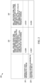
- FIG. 2 is a table 200 of primary synchronization signal sequence to secondary synchronization signal sequence, and secondary synchronization signal sequence to secondary synchronization signal sequence cross-correlation performance comparisons for two different identity to secondary synchronization signal sequence mapping schemes.
- PSS-SSS and SSS-SSS cross-correlation performances are presented for two different cell ID to SSS sequence mapping schemes.
- the first row 210 represents the performance in accordance with the cited reference, R1-1708160
- the second row 220 represents the performance in accordance with equations (2) and (3) in accordance with the teachings of at least one embodiment of the present application.
- a first column 230 corresponds to a maximum primary synchronization signal sequence to secondary synchronization signal sequence cross-correlation power normalized by peak primary synchronization signal sequence autocorrelation power with multiple integer carrier frequency offset hypothesis for a network having 1008 cell IDs, and a carrier frequency offset in the range of -3 to 3 sub-carrier spacing with a correlation in the time-domain.
- a second column 240 corresponds to a maximum secondary synchronization signal sequence cross-correlation power normalized by secondary synchronization signal sequence autocorrelation power with carrier frequency offset for a network having 1008 cell IDs, and a carrier frequency offset in the range of -0.5 to 0.5 sub-carrier spacing with a correlation in the frequency-domain.
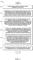
- FIG. 3 is a flow diagram 300 of a method for establishing a set of a plurality of synchronization signal sequences to be used in determining the identification of a communication target, according to a possible embodiment.
- the method provides for determining 302 an expected maximum carrier frequency offset value, and determining 304 a set of possible sequence values having a predetermined length, where each sequence value in the set is based upon a first maximum length sequence having a first cyclic shift, and is based upon a second maximum length sequence having a second cyclic shift.
- a subset of sequence values to be used as synchronization signal sequences for determining the identification of a communication target is selected 306 from the set of possible sequence values.
- the selected subset of sequence values includes no more than one sequence value from any group of possible sequence values from the determined set where (a) a value of a difference between the second cyclic shift of the second maximum length sequence and the first cyclic shift of the first maximum length sequence upon which each of the possible sequence values in the group are based are equal 308, and (b) the difference between the respective first cyclic shift value of the first maximum length upon which each of the possible sequence values in the group are based for any two of the possible sequence values in the group are less than or equal to the determined expected maximum carrier frequency offset value 310.
- Each one of the selected subset of values are then assigned 312 to a respective one of the communication targets.
- the first maximum length sequence and the second maximum length sequence are each a binary phase shift keying maximum length sequence, and each of the possible sequence values is generated via an element-wise multiplication of the first maximum length sequence having a first cyclic shift and the second maximum length sequence having a second cyclic shift.
- the communication targets can include one or more network entities included as part of a network, where the network entities are each respectively associated with one or more communication areas, and where communication with the network can be facilitated via one of the one or more network entities.
- the selected subset of sequence values can be respectively associated with a secondary synchronization signal, where the secondary synchronization signal is mapped and transmitted on consecutive subcarriers in a frequency domain.
- a primary synchronization signal associated with the communication target can be used with the secondary synchronization signal to determine a physical identity value for the communication target, where in addition to a physical identity value for the communication target, the primary synchronization signal and the secondary synchronization signal associated with a particular communication target can be used to determine at least some communication characteristics for use with subsequent communications with the communication target.
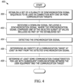
- FIG. 4 is a flow diagram 400 in a user equipment for receiving a mapped synchronization signal sequence.
- the method includes establishing a set of a plurality of synchronization signal sequences to be used in connection with one or more communication targets.
- the set of plurality of synchronization signal sequences can be established 300 as outlined in FIG. 3 , including the subsequent assignment of each one of the selected subset of values included as part of the established set to a respective one of the communication targets.
- the downlink signal including a synchronization signal is then received 402, where the synchronization signal comprises one of the selected subset of values included as part of the established set.
- the synchronization signal is then detected 404.
- an identity of a communication target can be determined 406 at least in part from the synchronization signal, which is detected.
- the selected subset of sequence values can be respectively associated with a secondary synchronization signal, where the secondary synchronization signal is mapped and transmitted on consecutive subcarriers in a frequency domain.
- a primary synchronization signal associated with the communication target can be used with the secondary synchronization signal to determine a physical identity value for the communication target, where in addition to a physical identity value for the communication target, the primary synchronization signal and the secondary synchronization signal associated with a particular communication target can be used to determine 408 at least some communication characteristics for use with subsequent communications with the communication target.
- the first maximum length sequence and the second maximum length sequence are each a binary phase shift keying maximum length sequence, and each of the possible sequence values can be generated via an element-wise multiplication of the first maximum length sequence having a first cyclic shift and the second maximum length sequence having a second cyclic shift.
- the communication targets can include one or more network entities included as part of a network, where the network entities are each respectively associated with one or more communication areas, and where communication with the network by the user equipment can be facilitated via one of the one or more network entities.
- the communication target can additionally and/or alternatively include a direct communication connection with another user equipment.
- FIG. 5 is a flow diagram 500 in a network entity for transmitting a mapped synchronization signal sequence.
- the method similar to the flow diagram illustrated in FIG. 4 can include establishing a set of a plurality of synchronization signal sequences to be used in connection with one or more communication targets.
- the set of plurality of synchronization signal sequences can be established 300 as outlined in FIG. 3 , including the subsequent assignment of each one of the selected subset of values included as part of the established set to a respective one of the communication targets.
- the downlink signal including a synchronization signal is then transmitted 502, where the synchronization signal comprises one of the selected subset of values included as part of the established set.
- FIG. 6 is an example block diagram of an apparatus 600, such as the wireless communication device 110, according to a possible embodiment.
- the apparatus 600 can include a housing 610, a controller 620 within the housing 610, audio input and output circuitry 630 coupled to the controller 620, a display 640 coupled to the controller 620, a transceiver 650 coupled to the controller 620, an antenna 655 coupled to the transceiver 650, a user interface 660 coupled to the controller 620, a memory 670 coupled to the controller 620, and a network interface 680 coupled to the controller 620.
- the apparatus 600 can perform the methods described in all the embodiments
- the display 640 can be a viewfinder, a liquid crystal display (LCD), a light emitting diode (LED) display, a plasma display, a projection display, a touch screen, or any other device that displays information.
- the transceiver 650 can include a transmitter and/or a receiver.
- the audio input and output circuitry 630 can include a microphone, a speaker, a transducer, or any other audio input and output circuitry.
- the user interface 660 can include a keypad, a keyboard, buttons, a touch pad, a joystick, a touch screen display, another additional display, or any other device useful for providing an interface between a user and an electronic device.
- the network interface 680 can be a Universal Serial Bus (USB) port, an Ethernet port, an infrared transmitter/receiver, an IEEE 1394 port, a WLAN transceiver, or any other interface that can connect an apparatus to a network, device, or computer and that can transmit and receive data communication signals.
- the memory 670 can include a random access memory, a read only memory, an optical memory, a solid state memory, a flash memory, a removable memory, a hard drive, a cache, or any other memory that can be coupled to an apparatus.
- the apparatus 600 or the controller 620 may implement any operating system, such as Microsoft Windows ® , UNIX ® , or LINUX ® , Android TM , or any other operating system.
- Apparatus operation software may be written in any programming language, such as C, C++, Java or Visual Basic, for example.
- Apparatus software may also run on an application framework, such as, for example, a Java ® framework, a .NET ® framework, or any other application framework.
- the software and/or the operating system may be stored in the memory 670 or elsewhere on the apparatus 600.
- the apparatus 600 or the controller 620 may also use hardware to implement disclosed operations.
- the controller 620 may be any programmable processor.
- Disclosed embodiments may also be implemented on a general-purpose or a special purpose computer, a programmed microprocessor or microprocessor, peripheral integrated circuit elements, an application-specific integrated circuit or other integrated circuits, hardware/electronic logic circuits, such as a discrete element circuit, a programmable logic device, such as a programmable logic array, field programmable gate-array, or the like.
- the controller 620 may be any controller or processor device or devices capable of operating an apparatus and implementing the disclosed embodiments. Some or all of the additional elements of the apparatus 600 can also perform some or all of the operations of the disclosed embodiments.
- the method of this disclosure can be implemented on a programmed processor.
- the controllers, flowcharts, and modules may also be implemented on a general purpose or special purpose computer, a programmed microprocessor or microcontroller and peripheral integrated circuit elements, an integrated circuit, a hardware electronic or logic circuit such as a discrete element circuit, a programmable logic device, or the like.
- any device on which resides a finite state machine capable of implementing the flowcharts shown in the figures may be used to implement the processor functions of this disclosure.
Landscapes
- Engineering & Computer Science (AREA)
- Computer Networks & Wireless Communication (AREA)
- Signal Processing (AREA)
- Databases & Information Systems (AREA)
- Mobile Radio Communication Systems (AREA)
Abstract
Description
- The present disclosure is directed to a method and apparatus for the mapping of cell identities to synchronization signal sequences, and more particularly to the selection of a subset of sequence values to be used with the mapping of cell identities from a set of possible sequence values.
- Presently, user equipment, such as wireless communication devices, communicate with other communication devices using wireless signals, such as within a network environment that can include one or more cells within which various communication connections with the network and other devices operating within the network can be supported. Network environments often involve one or more sets of standards, which each define various aspects of any communication connection being made when using the corresponding standard within the network environment. Examples of developing and/or existing standards include new radio access technology (NR), Long Term Evolution (LTE), Universal Mobile Telecommunications Service (UMTS), Global System for Mobile Communication (GSM), and/or Enhanced Data GSM Environment (EDGE).
- While operating within a network, the standard will define the manner in which the user equipment communicates with the network including initiating a new connection or refreshing an existing connection that has somehow become stale, such as for example where synchronization between the user equipment and the network access point has been lost.
- As part of a low level acquisition process, when attempting to initiate a connection to a network having a cellular structure, the user equipment can at least sometimes attempt to discover and acquire signaling from each of the nearby cells. This can involve receiving corresponding synchronization signals, which can include a respective primary and a respective secondary synchronization signal. In LTE, acquisition of a primary synchronization signal is initially attempted from which symbol timing and a partial cell identification can be determined. Various determinations of cross-correlations relative to a received signal with each of a predetermined set of synchronization signals can be used to determine the likely partial cell identification, such as the physical layer identity. Further more detailed information can then be determined through a subsequent acquisition of a secondary synchronization signal, including the frame timing, the rest of the cell identity, as well as other potential communication details, such as transmission mode and/or cyclic prefix duration.
- The present inventors have recognized, that the manner in which the predetermined set of synchronization signals including the secondary synchronization signals are selected from a list of possible sequences, and are mapped for use to the various cells and the corresponding cell identities can determine the relative ease with which the synchronization signal can be received and distinguished. By limiting which sequences can be used together including defining a mapping rule between a cell identity (ID) and relative cyclic shifts of multiple maximum length sequences, the cross-correlation performance can be enhanced, so that the potential for cell ID confusion during cell detection can be reduced.
- Presently, user equipment, such as wireless communication devices, communicate with other communication devices using wireless signals. According to a possible embodiment, a method is provided. The method includes determining an expected maximum carrier frequency offset value, and determining a set of possible sequence values having a predetermined length, where each sequence value in the set is based upon a first maximum length sequence having a first cyclic shift, and is based upon a second maximum length sequence having a second cyclic shift. A subset of sequence values to be used as synchronization signal sequences for determining the identification of a communication target is selected from the set of possible sequence values. The selected subset of sequence values includes no more than one sequence value from any group of possible sequence values from the determined set where (a) a value of a difference between the second cyclic shift of the second maximum length sequence and the first cyclic shift of the first maximum length sequence upon which each of the possible sequence values in the group are based are equal, and (b) the difference between the respective first cyclic shift value of the first maximum length upon which each of the possible sequence values in the group are based for any two of the possible sequence values in the group are less than or equal to the determined expected maximum carrier frequency offset value. Each one of the selected subset of values is assigned to a respective one of the communication targets.
- In some embodiments, the first maximum length sequence and the second maximum length sequence are each a binary phase shift keying maximum length sequence, and each of the possible sequence values is generated via an element-wise multiplication of the first maximum length sequence having a first cyclic shift and the second maximum length sequence having a second cyclic shift.
- According to a possible embodiment, a method in a user equipment is provided. The method includes establishing a set of a plurality of synchronization signal sequences to be used in connection with one or more communication targets. Establishing the set of plurality of synchronization signal sequences includes determining an expected maximum carrier frequency offset value, and determining a set of possible sequence values having a predetermined length, where each sequence value in the set is based upon a first maximum length sequence having a first cyclic shift, and is based upon a second maximum length sequence having a second cyclic shift. A subset of sequence values to be used as synchronization signal sequences for determining the identification of a communication target is selected from the set of possible sequence values. The selected subset of sequence values includes no more than one sequence value from any group of possible sequence values from the determined set where (a) a value of a difference between the second cyclic shift of the second maximum length sequence and the first cyclic shift of the first maximum length sequence upon which each of the possible sequence values in the group are based are equal, and (b) the difference between the respective first cyclic shift value of the first maximum length upon which each of the possible sequence values in the group are based for any two of the possible sequence values in the group are less than or equal to the determined expected maximum carrier frequency offset value. Each one of the selected subset of values is assigned to a respective one of the communication targets. A downlink signal including a synchronization signal is received, where the synchronization signal comprises one of the selected subset of values included as part of the established set. The synchronization signal is then detected.
- In some embodiments, an identity of a communication target is determined at least in part from the synchronization signal, which is detected.
- In some embodiments, the communication targets include one or more network entities included as part of a network, where the network entities are each respectively associated with one or more communication areas, and where communication with the network by the user equipment can be facilitated via one of the one or more network entities.
- In some embodiments, the communication target includes a direct communication connection with another user equipment.
- According to a possible embodiment, a user equipment in a communication network is provided. The user equipment includes a controller that establishes a set of a plurality of synchronization signal sequences to be used with one or more communication targets. The plurality of synchronization signal sequences are identified through a determination of an expected maximum carrier frequency offset value, and a determination of a set of possible sequence values having a predetermined length. Each sequence value in the set is based upon a first maximum length sequence having a first cyclic shift, and is based upon a second maximum length sequence having a second cyclic shift, wherein a subset of sequence values to be used as synchronization signal sequences for determining the identification of each one of the one or more communication targets are selected from the set of possible sequence values. The selected subset of sequence values includes no more than one sequence value from any group of possible sequence values from the determined set where (a) a value of a difference between the second cyclic shift of the second maximum length sequence and the first cyclic shift of the first maximum length sequence upon which each of the possible sequence values in the group are based are equal, and (b) the difference between the respective first cyclic shift value of the first maximum length upon which each of the possible sequence values in the group are based for any two of the possible sequence values in the group are less than or equal to the determined expected maximum carrier frequency offset value. Each one of the selected subset of values included as part of the established set is assigned to a respective one of the communication targets. The user equipment further includes a transceiver that receives a downlink signal including a synchronization signal, where the synchronization signal comprises one of the selected subset of values included as part of the established set. The controller further detects the synchronization signal from the received downlink signal.
- According to a possible embodiment, a method in a network entity is provided. The method includes establishing a set of a plurality of synchronization signal sequences to be used in connection with one or more communication targets. Establishing the set of plurality of synchronization signal sequences includes determining an expected maximum carrier frequency offset value, and determining a set of possible sequence values having a predetermined length, where each sequence value in the set is based upon a first maximum length sequence having a first cyclic shift, and is based upon a second maximum length sequence having a second cyclic shift. A subset of sequence values to be used as synchronization signal sequences for determining the identification of a communication target is selected from the set of possible sequence values. The selected subset of sequence values includes no more than one sequence value from any group of possible sequence values from the determined set where (a) a value of a difference between the second cyclic shift of the second maximum length sequence and the first cyclic shift of the first maximum length sequence upon which each of the possible sequence values in the group are based are equal, and (b) the difference between the respective first cyclic shift value of the first maximum length upon which each of the possible sequence values in the group are based for any two of the possible sequence values in the group are less than or equal to the determined expected maximum carrier frequency offset value. Each one of the selected subset of values is assigned to a respective one of the communication targets. A downlink signal including a synchronization signal is transmitted, where the synchronization signal comprises one of the selected subset of values included as part of the established set.
- According to a possible embodiment, a network entity in a communication network is provided. The network entity includes a controller that establishes a set of a plurality of synchronization signal sequences to be used with one or more communication targets. The plurality of synchronization signal sequences are identified through a determination of an expected maximum carrier frequency offset value, and a determination of a set of possible sequence values having a predetermined length. Each sequence value in the set is based upon a first maximum length sequence having a first cyclic shift, and is based upon a second maximum length sequence having a second cyclic shift, wherein a subset of sequence values to be used as synchronization signal sequences for determining the identification of each one of the one or more communication targets are selected from the set of possible sequence values. The selected subset of sequence values includes no more than one sequence value from any group of possible sequence values from the determined set where (a) a value of a difference between the second cyclic shift of the second maximum length sequence and the first cyclic shift of the first maximum length sequence upon which each of the possible sequence values in the group are based are equal, and (b) the difference between the respective first cyclic shift value of the first maximum length upon which each of the possible sequence values in the group are based for any two of the possible sequence values in the group are less than or equal to the determined expected maximum carrier frequency offset value. Each one of the selected subset of values included as part of the established set is assigned to a respective one of the communication targets. The network entity further includes a transceiver that transmits a downlink signal including a synchronization signal, where the synchronization signal comprises one of the selected subset of values included as part of the established set.
- These and other objects, features, and advantages of the present application are evident from the following description of one or more preferred embodiments, with reference to the accompanying drawings.
-
-
FIG. 1 is a block diagram of an exemplary network environment in which the present invention is adapted to operate; -
FIG. 2 is a table of primary synchronization signal sequence to secondary synchronization signal sequence, and secondary synchronization signal sequence to secondary synchronization signal sequence cross-correlation performance comparisons for two different identity to secondary synchronization signal sequence mapping schemes; -
FIG. 3 is a flow diagram of a method for establishing a set of a plurality of synchronization signal sequences to be used in determining the identification of a communication target; -
FIG. 4 is a flow diagram in a user equipment for receiving a mapped synchronization signal sequence; -
FIG. 5 is a flow diagram in a network entity for transmitting a mapped synchronization signal sequence; and -
FIG. 6 is an example block diagram of an apparatus according to a possible embodiment. - While the present disclosure is susceptible of embodiment in various forms, there is shown in the drawings and will hereinafter be described presently preferred embodiments with the understanding that the present disclosure is to be considered an exemplification of the invention and is not intended to limit the invention to the specific embodiments illustrated.
- Embodiments provide a method and apparatus for mapping of cell identities to synchronization signal sequences.
-
FIG. 1 is an example block diagram of asystem 100 according to a possible embodiment. Thesystem 100 can include awireless communication device 110, such as User Equipment (UE), abase station 120, such as an enhanced NodeB (eNB) or next generation NodeB (gNB), and anetwork 130. Thewireless communication device 110 can be a wireless terminal, a portable wireless communication device, a smartphone, a cellular telephone, a flip phone, a personal digital assistant, a personal computer, a selective call receiver, a tablet computer, a laptop computer, or any other device that is capable of sending and receiving communication signals on a wireless network. - The
network 130 can include any type of network that is capable of sending and receiving wireless communication signals. For example, thenetwork 130 can include a wireless communication network, a cellular telephone network, a Time Division Multiple Access (TDMA)-based network, a Code Division Multiple Access (CDMA)-based network, an Orthogonal Frequency Division Multiple Access (OFDMA)-based network, a Long Term Evolution (LTE) network, a 5th generation (5G) network, a 3rd Generation Partnership Project (3GPP)-based network, a satellite communications network, a high altitude platform network, the Internet, and/or other communications networks. - In a fifth generation (5G) radio access technology (RAT) based wireless network, the number of cells generally meaningfully increases for area capacity enhancement and for use of high frequency bands. Thus, synchronization signal (SS) sequences carrying cell identities (ID) should have good cross-correlation performances to allow flexible network deployment without complex cell ID planning and for reducing potential cell ID confusion at a user equipment (UE). Furthermore, the cross-correlation performance should be robust to carrier frequency offset (CFO), as the UE has to detect the SS sequences without perfect timing and frequency synchronization.
- In 3GPP new RAT (NR), three primary synchronization signal (PSS) sequences were defined as follows:
frequency domain-based pure binary phase shift keying (BPSK) maximum length sequence (M sequence) - 1 polynomial: decimal 145 (i.e. g(x) = x7 + x4 + 1)
- 3 cyclic shifts (0, 43, 86) in the frequency domain to get the 3 PSS sequences
- Initial polynomial shift register values: 1110110
- According to 3GPP TS 38.211 V15.0.0, the sequence d PSS(n) for the primary synchronization signal is defined by


- Secondary synchronization signal (SSS) sequences can be generated via element-wise multiplication of two BPSK m-sequences, each with its own cyclic shift. If two generator polynomials for m-sequences are preferred-pair of m-sequences, the SSS sequences are Gold sequences and their cyclic shifts. For example, two generator polynomials can be g 0(x) = x 7 + x 4 + 1 and g 1(x) = x 7 + x + 1 with initial state [0000001]. Considering that residual CFO due to estimation error and/or high Doppler spread may exist even after PSS based CFO estimation and compensation, SSS sequences should have good cross-correlation performances at least under CFO of up to +/-0.5 subcarrier spacing.
- This present disclosure presents methods to select a set of SSS sequences, such as from given Gold sequences and their cyclic shifts, which has robust cross-correlation performances under CFO, by defining a proper mapping rule between a cell ID and cyclic shifts of two m-sequences used for the Gold sequences.
- The mapping of a cell ID to a SSS sequence in at least some alternative instances including according to the proposal in the reference R1-1708160, entitled "Remaining details for synchronization signals", shown below, may cause cell ID confusion at UE with residual CFO in multi-cell environments.


- This is because the proposed mapping in said identified proposal, namely R1-1708160, generates one or more SSS sequence pairs, wherein, in each SSS sequence pair, one sequence is 1-cyclic shift of the other sequence.
- According to a possible embodiment of the present application, the length-L SSS sequences d(0),...,d(L-1) based on 2 preferred-pair m-sequences can be described as follows:


index 


- In one embodiment, any two SSS sequences having the common (m1 - m0) value have two different m0 values, wherein m1 is larger than m0, and a magnitude of a difference of the two m0 values is larger than a first value, wherein the first value is dependent on the maximum allowed (or expected) residual CFO. In one example, the first value is the nearest integer larger than a magnitude of the maximum allowed (or expected) residual CFO. In equation (1), a unique SSS sequence is determined by the values m0 and (m1 - m0), where m0 = 0, 1, ..., L-1, and m1 - m0 = 0, 1, ..., L-1. Thus, the total number of unique sequences which can be generated from the above equation (1) are L 2. Further, L sequences from L pairs of (m0, m1), which result in the same (m1 - m0) value, are L cyclic shifted versions of one sequence. Assuming that the above SSS sequences are directly mapped to consecutive subcarriers in the frequency domain, any two SSS sequences which are 1-cyclic shift of each other may suffer from high cross-correlation in frequency domain due to residual CFO up to +/-0.5 subcarrier spacing, wherein the subcarrier spacing refers to the subcarrier spacing of PSS and SSS. Thus, among a set of SSS sequences, any two SSS sequences having the common (mi - m0) value should have 2 or larger difference for the m0 value so that the two SSS sequences are two or more cyclic shifts of each other.
- In one example, cyclic shifts m0 and m1 applied to generate a SSS sequence are determined as follows:


- In another example, cyclic shifts m0 and m1 for a length-L SSS sequence is determined as follows:


-
FIG. 2 is a table 200 of primary synchronization signal sequence to secondary synchronization signal sequence, and secondary synchronization signal sequence to secondary synchronization signal sequence cross-correlation performance comparisons for two different identity to secondary synchronization signal sequence mapping schemes. In the illustrated table, PSS-SSS and SSS-SSS cross-correlation performances are presented for two different cell ID to SSS sequence mapping schemes. Thefirst row 210 represents the performance in accordance with the cited reference, R1-1708160, and thesecond row 220 represents the performance in accordance with equations (2) and (3) in accordance with the teachings of at least one embodiment of the present application. - In the table, a
first column 230 corresponds to a maximum primary synchronization signal sequence to secondary synchronization signal sequence cross-correlation power normalized by peak primary synchronization signal sequence autocorrelation power with multiple integer carrier frequency offset hypothesis for a network having 1008 cell IDs, and a carrier frequency offset in the range of -3 to 3 sub-carrier spacing with a correlation in the time-domain. Asecond column 240 corresponds to a maximum secondary synchronization signal sequence cross-correlation power normalized by secondary synchronization signal sequence autocorrelation power with carrier frequency offset for a network having 1008 cell IDs, and a carrier frequency offset in the range of -0.5 to 0.5 sub-carrier spacing with a correlation in the frequency-domain. - In the table, it is shown that the proposed mapping according to equations (2) and (3) can avoid high SSS cross-correlation, while the mapping scheme in the above noted reference, R1-1708160, suffers from a normalized SSS cross-correlation power close to 1. The proposed mapping according to equations (2) and (3) noted above related to the teachings of at least one embodiment of the present application alternatively produces a normalized SSS cross-correlation power, which is approximately 0.4246.
-
FIG. 3 is a flow diagram 300 of a method for establishing a set of a plurality of synchronization signal sequences to be used in determining the identification of a communication target, according to a possible embodiment. The method provides for determining 302 an expected maximum carrier frequency offset value, and determining 304 a set of possible sequence values having a predetermined length, where each sequence value in the set is based upon a first maximum length sequence having a first cyclic shift, and is based upon a second maximum length sequence having a second cyclic shift. A subset of sequence values to be used as synchronization signal sequences for determining the identification of a communication target is selected 306 from the set of possible sequence values. The selected subset of sequence values includes no more than one sequence value from any group of possible sequence values from the determined set where (a) a value of a difference between the second cyclic shift of the second maximum length sequence and the first cyclic shift of the first maximum length sequence upon which each of the possible sequence values in the group are based are equal 308, and (b) the difference between the respective first cyclic shift value of the first maximum length upon which each of the possible sequence values in the group are based for any two of the possible sequence values in the group are less than or equal to the determined expected maximum carrier frequency offsetvalue 310. Each one of the selected subset of values are then assigned 312 to a respective one of the communication targets. - In at least some instances, the first maximum length sequence and the second maximum length sequence are each a binary phase shift keying maximum length sequence, and each of the possible sequence values is generated via an element-wise multiplication of the first maximum length sequence having a first cyclic shift and the second maximum length sequence having a second cyclic shift. In some of the same or other instances, the communication targets can include one or more network entities included as part of a network, where the network entities are each respectively associated with one or more communication areas, and where communication with the network can be facilitated via one of the one or more network entities.
- In some instances, the selected subset of sequence values can be respectively associated with a secondary synchronization signal, where the secondary synchronization signal is mapped and transmitted on consecutive subcarriers in a frequency domain. In some of these instances, a primary synchronization signal associated with the communication target can be used with the secondary synchronization signal to determine a physical identity value for the communication target, where in addition to a physical identity value for the communication target, the primary synchronization signal and the secondary synchronization signal associated with a particular communication target can be used to determine at least some communication characteristics for use with subsequent communications with the communication target.
-
FIG. 4 is a flow diagram 400 in a user equipment for receiving a mapped synchronization signal sequence. The method includes establishing a set of a plurality of synchronization signal sequences to be used in connection with one or more communication targets. In at least some instances, the set of plurality of synchronization signal sequences can be established 300 as outlined inFIG. 3 , including the subsequent assignment of each one of the selected subset of values included as part of the established set to a respective one of the communication targets. The downlink signal including a synchronization signal is then received 402, where the synchronization signal comprises one of the selected subset of values included as part of the established set. The synchronization signal is then detected 404. - In some instances, an identity of a communication target can be determined 406 at least in part from the synchronization signal, which is detected.
- In some instances, the selected subset of sequence values can be respectively associated with a secondary synchronization signal, where the secondary synchronization signal is mapped and transmitted on consecutive subcarriers in a frequency domain. In some of these instances, a primary synchronization signal associated with the communication target can be used with the secondary synchronization signal to determine a physical identity value for the communication target, where in addition to a physical identity value for the communication target, the primary synchronization signal and the secondary synchronization signal associated with a particular communication target can be used to determine 408 at least some communication characteristics for use with subsequent communications with the communication target.
- In some of the same or other instances, the first maximum length sequence and the second maximum length sequence are each a binary phase shift keying maximum length sequence, and each of the possible sequence values can be generated via an element-wise multiplication of the first maximum length sequence having a first cyclic shift and the second maximum length sequence having a second cyclic shift.
- The communication targets can include one or more network entities included as part of a network, where the network entities are each respectively associated with one or more communication areas, and where communication with the network by the user equipment can be facilitated via one of the one or more network entities. The communication target can additionally and/or alternatively include a direct communication connection with another user equipment.
-
FIG. 5 is a flow diagram 500 in a network entity for transmitting a mapped synchronization signal sequence. The method similar to the flow diagram illustrated inFIG. 4 , can include establishing a set of a plurality of synchronization signal sequences to be used in connection with one or more communication targets. In at least some instances, the set of plurality of synchronization signal sequences can be established 300 as outlined inFIG. 3 , including the subsequent assignment of each one of the selected subset of values included as part of the established set to a respective one of the communication targets. The downlink signal including a synchronization signal is then transmitted 502, where the synchronization signal comprises one of the selected subset of values included as part of the established set. - It should be understood that, notwithstanding the particular steps as shown in the figures, a variety of additional or different steps can be performed depending upon the embodiment, and one or more of the particular steps can be rearranged, repeated or eliminated entirely depending upon the embodiment. Also, some of the steps performed can be repeated on an ongoing or continuous basis simultaneously while other steps are performed. Furthermore, different steps can be performed by different elements or in a single element of the disclosed embodiments.
-
FIG. 6 is an example block diagram of anapparatus 600, such as thewireless communication device 110, according to a possible embodiment. Theapparatus 600 can include ahousing 610, acontroller 620 within thehousing 610, audio input andoutput circuitry 630 coupled to thecontroller 620, adisplay 640 coupled to thecontroller 620, atransceiver 650 coupled to thecontroller 620, anantenna 655 coupled to thetransceiver 650, auser interface 660 coupled to thecontroller 620, amemory 670 coupled to thecontroller 620, and anetwork interface 680 coupled to thecontroller 620. Theapparatus 600 can perform the methods described in all the embodiments - The
display 640 can be a viewfinder, a liquid crystal display (LCD), a light emitting diode (LED) display, a plasma display, a projection display, a touch screen, or any other device that displays information. Thetransceiver 650 can include a transmitter and/or a receiver. The audio input andoutput circuitry 630 can include a microphone, a speaker, a transducer, or any other audio input and output circuitry. Theuser interface 660 can include a keypad, a keyboard, buttons, a touch pad, a joystick, a touch screen display, another additional display, or any other device useful for providing an interface between a user and an electronic device. Thenetwork interface 680 can be a Universal Serial Bus (USB) port, an Ethernet port, an infrared transmitter/receiver, an IEEE 1394 port, a WLAN transceiver, or any other interface that can connect an apparatus to a network, device, or computer and that can transmit and receive data communication signals. Thememory 670 can include a random access memory, a read only memory, an optical memory, a solid state memory, a flash memory, a removable memory, a hard drive, a cache, or any other memory that can be coupled to an apparatus. - The
apparatus 600 or thecontroller 620 may implement any operating system, such as Microsoft Windows®, UNIX®, or LINUX®, Android™, or any other operating system. Apparatus operation software may be written in any programming language, such as C, C++, Java or Visual Basic, for example. Apparatus software may also run on an application framework, such as, for example, a Java® framework, a .NET® framework, or any other application framework. The software and/or the operating system may be stored in thememory 670 or elsewhere on theapparatus 600. Theapparatus 600 or thecontroller 620 may also use hardware to implement disclosed operations. For example, thecontroller 620 may be any programmable processor. Disclosed embodiments may also be implemented on a general-purpose or a special purpose computer, a programmed microprocessor or microprocessor, peripheral integrated circuit elements, an application-specific integrated circuit or other integrated circuits, hardware/electronic logic circuits, such as a discrete element circuit, a programmable logic device, such as a programmable logic array, field programmable gate-array, or the like. In general, thecontroller 620 may be any controller or processor device or devices capable of operating an apparatus and implementing the disclosed embodiments. Some or all of the additional elements of theapparatus 600 can also perform some or all of the operations of the disclosed embodiments. - The method of this disclosure can be implemented on a programmed processor. However, the controllers, flowcharts, and modules may also be implemented on a general purpose or special purpose computer, a programmed microprocessor or microcontroller and peripheral integrated circuit elements, an integrated circuit, a hardware electronic or logic circuit such as a discrete element circuit, a programmable logic device, or the like. In general, any device on which resides a finite state machine capable of implementing the flowcharts shown in the figures may be used to implement the processor functions of this disclosure.
- While this disclosure has been described with specific embodiments thereof, it is evident that many alternatives, modifications, and variations will be apparent to those skilled in the art. For example, various components of the embodiments may be interchanged, added, or substituted in the other embodiments. Also, all of the elements of each figure are not necessary for operation of the disclosed embodiments. For example, one of ordinary skill in the art of the disclosed embodiments would be enabled to make and use the teachings of the disclosure by simply employing the elements of the independent claims. Accordingly, embodiments of the disclosure as set forth herein are intended to be illustrative, not limiting. Various changes may be made without departing from the spirit and scope of the disclosure.
- In this document, relational terms such as "first," "second," and the like may be used solely to distinguish one entity or action from another entity or action without necessarily requiring or implying any actual such relationship or order between such entities or actions. The phrase "at least one of,"" "at least one selected from the group of," or "at least one selected from" followed by a list is defined to mean one, some, or all, but not necessarily all of, the elements in the list. The terms "comprises," "comprising," "including," or any other variation thereof, are intended to cover a non-exclusive inclusion, such that a process, method, article, or apparatus that comprises a list of elements does not include only those elements but may include other elements not expressly listed or inherent to such process, method, article, or apparatus. An element proceeded by "a," "an," or the like does not, without more constraints, preclude the existence of additional identical elements in the process, method, article, or apparatus that comprises the element. Also, the term "another" is defined as at least a second or more. The terms "including," "having," and the like, as used herein, are defined as "comprising." Furthermore, the background section is written as the inventor's own understanding of the context of some embodiments at the time of filing and includes the inventor's own recognition of any problems with existing technologies and/or problems experienced in the inventor's own work.
- Further aspects of the invention are provided by the subject matter of the following numbered clauses:
- 1. A method comprising: determining an expected maximum carrier frequency offset value; determining a set of possible sequence values having a predetermined length, where each sequence value in the set is based upon a first maximum length sequence having a first cyclic shift, and is based upon a second maximum length sequence having a second cyclic shift; selecting from the set of possible sequence values a subset of sequence values to be used as synchronization signal sequences for determining the identification of a communication target, the selected subset of sequence values including no more than one sequence value from any group of possible sequence values from the determined set where (a) a value of a difference between the second cyclic shift of the second maximum length sequence and the first cyclic shift of the first maximum length sequence upon which each of the possible sequence values in the group are based are equal, and (b) the difference between the respective first cyclic shift value of the first maximum length upon which each of the possible sequence values in the group are based for any two of the possible sequence values in the group are less than or equal to the determined expected maximum carrier frequency offset value; and assigning each one of the selected subset of values to a respective one of the communication targets.
- 2. A method in accordance with clause 1, wherein the first maximum length sequence and the second maximum length sequence are each a binary phase shift keying maximum length sequence, and each of the possible sequence values is generated via an element-wise multiplication of the first maximum length sequence having a first cyclic shift and the second maximum length sequence having a second cyclic shift.
- 3. A method in accordance with clause 1, wherein the communication targets include one or more network entities included as part of a network, where the network entities are each respectively associated with one or more communication areas, and where communication with the network can be facilitated via one of the one or more network entities.
- 4. A method in accordance with clause 1, wherein the selected subset of sequence values are respectively associated with a secondary synchronization signal.
- 5. A method in accordance with clause 4, wherein the secondary synchronization signal is mapped and transmitted on consecutive subcarriers in a frequency domain.
- 6. A method in accordance with clause 4, wherein a primary synchronization signal associated with the communication target is used with the secondary synchronization signal to determine a physical identity value for the communication target.
- 7. A method in accordance with clause 6, where in addition to a physical identity value for the communication target, the primary synchronization signal and the secondary synchronization signal associated with a particular communication target can be used to determine at least some communication characteristics for use with subsequent communications with the communication target.
- 8. A method in a user equipment, the method comprising: establishing a set of a plurality of synchronization signal sequences to be used in connection with one or more communication targets, where establishing the set of plurality of synchronization signal sequences includes determining an expected maximum carrier frequency offset value; determining a set of possible sequence values having a predetermined length, where each sequence value in the set is based upon a first maximum length sequence having a first cyclic shift, and is based upon a second maximum length sequence having a second cyclic shift; selecting from the set of possible sequence values a subset of sequence values to be included as part of the established set, the selected subset of sequence values including no more than one sequence value from any group of possible sequence values from the determined set where (a) a value of a difference between the second cyclic shift of the second maximum length sequence and the first cyclic shift of the first maximum length sequence upon which each of the possible sequence values in the group are based are equal, and (b) the difference between the respective first cyclic shift value of the first maximum length upon which each of the possible sequence values in the group are based for any two of the possible sequence values in the group are less than or equal to the determined expected maximum carrier frequency offset value; assigning each one of the selected subset of values included as part of the established set to a respective one of the communication targets; receiving a downlink signal including a synchronization signal, where the synchronization signal comprises one of the selected subset of values included as part of the established set; and detecting the synchronization signal.
- 9. A method in accordance with clause 8, further comprising determining an identity of a communication target at least in part from the synchronization signal, which is detected.
- 10. A method in accordance with clause 8, wherein the assigned one of the selected subset of sequence values associated with a communication target is related to a corresponding secondary synchronization signal, which can be detected.
- 11. A method in accordance with clause 10, wherein a primary synchronization signal corresponding to the communication target is used by the user equipment with the secondary synchronization signal to determine a physical identity value for the communication target.
- 12. A method in accordance with clause 10, wherein the secondary synchronization signal is mapped and transmitted on consecutive subcarriers in a frequency domain.
- 13. A method in accordance with clause 12, where in addition to a physical identity value for the communication target, the primary synchronization signal and the secondary synchronization signal associated with a particular communication target can be used to determine at least some communication characteristics for use with subsequent communications between the user equipment and the communication target.
- 14. A method in accordance with clause 8, wherein the first maximum length sequence and the second maximum length sequence are each a binary phase shift keying maximum length sequence, and each of the possible sequence values is generated via an element-wise multiplication of the first maximum length sequence having a first cyclic shift and the second maximum length sequence having a second cyclic shift.
- 15. A method in accordance with clause 8, wherein the communication targets include one or more network entities included as part of a network, where the network entities are each respectively associated with one or more communication areas, and where communication with the network by the user equipment can be facilitated via one of the one or more network entities.
- 16. A method in accordance with clause 8, wherein the communication target includes a direct communication connection with another user equipment.
- 17. A user equipment in a communication network, the user equipment comprising: a controller that establishes a set of a plurality of synchronization signal sequences to be used with one or more communication targets, where the plurality of synchronization signal sequences are identified through a determination of an expected maximum carrier frequency offset value, and a determination of a set of possible sequence values having a predetermined length, where each sequence value in the set is based upon a first maximum length sequence having a first cyclic shift, and is based upon a second maximum length sequence having a second cyclic shift, wherein a subset of sequence values to be used as synchronization signal sequences for determining the identification of each one of the one or more communication targets are selected from the set of possible sequence values, the selected subset of sequence values including no more than one sequence value from any group of possible sequence values from the determined set where (a) a value of a difference between the second cyclic shift of the second maximum length sequence and the first cyclic shift of the first maximum length sequence upon which each of the possible sequence values in the group are based are equal, and (b) the difference between the respective first cyclic shift value of the first maximum length upon which each of the possible sequence values in the group are based for any two of the possible sequence values in the group are less than or equal to the determined expected maximum carrier frequency offset value, and wherein each one of the selected subset of values included as part of the established set is assigned to a respective one of the communication targets; and a transceiver that receives a downlink signal including a synchronization signal, where the synchronization signal comprises one of the selected subset of values included as part of the established set; and wherein the controller further detects the synchronization signal from the received downlink signal.
- 18. A user equipment in accordance with clause 17, wherein the communication target includes a network comprising one or more network entities respectively associated with one or more communication areas, and the user equipment communicates with the network via the one or more network entities.
- 19. A user equipment in accordance with clause 18, wherein the controller uses the detected synchronization signal to identify at least a partial physical-layer cell identity of one of the one or more network entities.
- 20. A user equipment in accordance with clause 17, wherein the communication target includes a direct communication connection with another user equipment.
Claims (15)
- A method comprising:determining a set of sequence values to be used as synchronization signal sequences, the set of sequence values having a predetermined length,wherein each sequence value in the set is based upon a first maximum length sequence having a first cyclic shift, and is based upon a second maximum length sequence having a second cyclic shift; andwherein for at least one group of possible sequence values from the determined set, where a value of a first cyclic shift difference between the second cyclic shift of the second maximum length sequence and the first cyclic shift of the first maximum length sequence upon which each of the possible sequence values in the group are based are equal, and a second cyclic shift difference between the respective first cyclic shift value of the first maximum length upon which each of the possible sequence values in the group are based for any two of the possible sequence values in the group are larger than or equal to a threshold value, where the threshold value is determined based on an expected maximum carrier frequency offset value; andassigning each one of the determined set of sequence values to respective at least one communication target of a plurality of communication targets, which includes each of the assigned ones of the determined set of sequence values being communicated to the respective at least one communication target of the plurality of communication targets.
- A method in accordance with claim 1, wherein the first maximum length sequence and the second maximum length sequence are each a binary phase shift keying maximum length sequence, and each of the possible sequence values is generated via an element-wise multiplication of the first maximum length sequence having the first cyclic shift and the second maximum length sequence having the second cyclic shift.
- A method in accordance with claim 1, wherein the plurality of communication targets include at least one network entity included as part of a network, where the at least one network entity are each respectively associated with at least one communication area, and where communication with the network can be facilitated via one of the at least one network entity.
- A method in accordance with claim 1, wherein the determined set of sequence values respectively correspond to a secondary synchronization signal associated with a communication target.
- A method in accordance with claim 4, wherein the secondary synchronization signal is mapped and transmitted on consecutive subcarriers in a frequency domain.
- A method in accordance with claim 4, wherein a primary synchronization signal associated with the communication target is used with the secondary synchronization signal to determine a physical identity value for the communication target.
- A method in accordance with claim 6, where in addition to a physical identity value for the communication target, the primary synchronization signal and the secondary synchronization signal associated with a particular communication target can be used to determine at least some communication characteristics for use with subsequent communications with the communication target.
- A method in a user equipment, the method comprising:establishing a set of a plurality of synchronization signal sequences to be used in connection with at least one communication target, the set of the plurality of synchronization signal sequences having a predetermined length,wherein each synchronization signal sequence in the set is based upon a first maximum length sequence having a first cyclic shift and a second maximum length sequence having a second cyclic shift, and corresponds to a respective identity of a plurality of identities associated with a respective communication target;wherein for at least one group of possible synchronization signal sequences from the established set, where a value of a first cyclic shift difference between the second cyclic shift of the second maximum length sequence and the first cyclic shift of the first maximum length sequence upon which each of the possible synchronization signal sequences in the group are based are equal, and a second cyclic shift difference between the respective first cyclic shift value of the first maximum length upon which each of the possible synchronization signal sequences in the group are based for any two of the possible synchronization signal sequences in the group are larger than or equal to a threshold value, where the threshold value is determined based on an expected maximum carrier frequency offset value;receiving a downlink signal including a synchronization signal, where the synchronization signal comprises one of the set of synchronization signal sequences; anddetecting the synchronization signal.
- A method in accordance with claim 8, further comprising determining an identity of a communication target at least in part from the synchronization signal, which is detected.
- A method in accordance with claim 8, wherein a synchronization signal sequence of the set corresponding to an identity associated with a communication target is used as a secondary synchronization signal.
- A method in accordance with claim 10, wherein a primary synchronization signal corresponding to the communication target is used by the user equipment with the secondary synchronization signal to determine a physical identity value for the communication target, where the identity is a physical identity.
- A method in accordance with claim 10, wherein the secondary synchronization signal is mapped and transmitted on consecutive subcarriers in a frequency domain.
- A user equipment in a communication network, the user equipment comprising:a transceiver;a controller coupled to the transceiver, that determines a set of sequence values to be used as synchronization signal sequences, the set of sequence values having a predetermined length, wherein each sequence value in the set is based upon a first maximum length sequence having a first cyclic shift, and is based upon a second maximum length sequence having a second cyclic shift, and wherein for at least one group of possible sequence values from the determined set, where a value of a first cyclic shift difference between the second cyclic shift of the second maximum length sequence and the first cyclic shift of the first maximum length sequence upon which each of the possible sequence values in the group are based are equal, and a second cyclic shift difference between the respective first cyclic shift value of the first maximum length upon which each of the possible sequence values in the group are based for any two of the possible sequence values in the group are larger than or equal to a threshold value, where the threshold value is determined based on an expected maximum carrier frequency offset value; andwherein each one of the determined set of sequence values is associated with respective at least one communication target;wherein the transceiver receives a downlink signal including a synchronization signal, where the synchronization signal comprises one of the determined set of sequence values; andwherein the controller further detects the synchronization signal from the received downlink signal.
- A user equipment in accordance with claim 13, wherein a communication target includes a network comprising at least one network entity respectively associated with at least one communication area, and the user equipment communicates with the network via the at least one network entity.
- A user equipment in accordance with claim 14, wherein the controller uses the detected synchronization signal to identify at least a partial physical-layer cell identity of one of the at least one network entity.
Applications Claiming Priority (3)
| Application Number | Priority Date | Filing Date | Title |
|---|---|---|---|
| US201762521331P | 2017-06-16 | 2017-06-16 | |
| PCT/US2018/037949 WO2018232373A1 (en) | 2017-06-16 | 2018-06-15 | Method and apparatus for establishing a set of a plurality of synchronization signal sequences to be used with one or more communication targets |
| EP18740953.7A EP3639419B1 (en) | 2017-06-16 | 2018-06-15 | Method and apparatus for establishing a set of a plurality of synchronization signal sequences to be used with one or more communication targets |
Related Parent Applications (2)
| Application Number | Title | Priority Date | Filing Date |
|---|---|---|---|
| EP18740953.7A Division-Into EP3639419B1 (en) | 2017-06-16 | 2018-06-15 | Method and apparatus for establishing a set of a plurality of synchronization signal sequences to be used with one or more communication targets |
| EP18740953.7A Division EP3639419B1 (en) | 2017-06-16 | 2018-06-15 | Method and apparatus for establishing a set of a plurality of synchronization signal sequences to be used with one or more communication targets |
Publications (1)
| Publication Number | Publication Date |
|---|---|
| EP4407901A1 true EP4407901A1 (en) | 2024-07-31 |
Family
ID=62916756
Family Applications (3)
| Application Number | Title | Priority Date | Filing Date |
|---|---|---|---|
| EP18740953.7A Active EP3639419B1 (en) | 2017-06-16 | 2018-06-15 | Method and apparatus for establishing a set of a plurality of synchronization signal sequences to be used with one or more communication targets |
| EP24175032.2A Pending EP4407901A1 (en) | 2017-06-16 | 2018-06-15 | Method and apparatus for establishing a set of a plurality of synchronization signal sequences to be used with one or more communication targets |
| EP24175047.0A Pending EP4391669A3 (en) | 2017-06-16 | 2018-06-15 | Method and apparatus for establishing a set of a plurality of synchronization signal sequences to be used with one or more communication targets |
Family Applications Before (1)
| Application Number | Title | Priority Date | Filing Date |
|---|---|---|---|
| EP18740953.7A Active EP3639419B1 (en) | 2017-06-16 | 2018-06-15 | Method and apparatus for establishing a set of a plurality of synchronization signal sequences to be used with one or more communication targets |
Family Applications After (1)
| Application Number | Title | Priority Date | Filing Date |
|---|---|---|---|
| EP24175047.0A Pending EP4391669A3 (en) | 2017-06-16 | 2018-06-15 | Method and apparatus for establishing a set of a plurality of synchronization signal sequences to be used with one or more communication targets |
Country Status (5)
| Country | Link |
|---|---|
| US (3) | US10609665B2 (en) |
| EP (3) | EP3639419B1 (en) |
| KR (1) | KR102676574B1 (en) |
| CN (3) | CN110663204B (en) |
| WO (1) | WO2018232373A1 (en) |
Families Citing this family (6)
| Publication number | Priority date | Publication date | Assignee | Title |
|---|---|---|---|---|
| RU2741997C1 (en) * | 2017-05-04 | 2021-02-01 | Хуавей Текнолоджиз Ко., Лтд. | Processing device, network node, client device and methods thereof |
| CN112615704B (en) * | 2018-08-10 | 2022-03-08 | 华为技术有限公司 | Method and device for transmitting synchronization signal |
| CN111565449B (en) * | 2019-02-14 | 2022-05-24 | 财团法人资讯工业策进会 | Base station for mobile communication system |
| US11463972B2 (en) * | 2019-06-12 | 2022-10-04 | Qualcomm Incorporated | Sidelink primary and secondary synchronization signal transmission |
| CN112188446B (en) * | 2019-07-05 | 2022-04-08 | 大唐移动通信设备有限公司 | Synchronization signal sending method, terminal, device and storage medium |
| EP4576621A1 (en) * | 2023-12-19 | 2025-06-25 | Nokia Technologies Oy | Synchronization |
Citations (1)
| Publication number | Priority date | Publication date | Assignee | Title |
|---|---|---|---|---|
| WO2018164414A1 (en) * | 2017-03-04 | 2018-09-13 | Lg Electronics Inc. | Method for transmitting synchronization signal in wireless communication system and apparatus therefor |
Family Cites Families (19)
| Publication number | Priority date | Publication date | Assignee | Title |
|---|---|---|---|---|
| DE60301384T2 (en) * | 2003-02-28 | 2006-03-09 | Alcatel | Method for transmitting packets with two different line codes and suitable transmitters and receivers |
| JP4367422B2 (en) * | 2006-02-14 | 2009-11-18 | ソニー株式会社 | Wireless communication apparatus and wireless communication method |
| JP5106531B2 (en) * | 2007-06-19 | 2012-12-26 | パナソニック株式会社 | Sequence allocation method, transmission method, radio mobile station apparatus, and base station apparatus |
| WO2009078785A1 (en) * | 2007-12-14 | 2009-06-25 | Telefonaktiebolaget L M Ericsson (Publ) | Methods and devices for communicating over a radio channel |
| CN102387582B (en) * | 2010-08-31 | 2014-11-26 | 联芯科技有限公司 | Detection method and device for cell group numbers of secondary synchronization sequences of LTE (long term evolution) system |
| US10064041B2 (en) * | 2013-01-31 | 2018-08-28 | Lg Electronics Inc. | Method for setting cyclic prefix for D2D (device-to-device) communication in radio communications system and apparatus therefor |
| GB2512127A (en) * | 2013-03-21 | 2014-09-24 | Sony Corp | Communications device and method |
| US9398062B2 (en) * | 2013-03-29 | 2016-07-19 | Intel IP Corporation | Timing synchronization in discovery signals |
| US9615341B2 (en) * | 2013-11-01 | 2017-04-04 | Futurewei Technologies, Inc. | System and method for transmitting a synchronization signal |
| US9584245B2 (en) * | 2014-03-26 | 2017-02-28 | National Central University | Non-coherent neighbor cell searching method |
| US9474016B2 (en) * | 2015-02-13 | 2016-10-18 | Freescale Semiconductor, Inc. | Cell search in a wireless communication network |
| CN106487494B (en) * | 2015-09-02 | 2019-06-28 | 华为技术有限公司 | Signal synchronization method and signal synchronization device |
| WO2017057984A1 (en) * | 2015-10-02 | 2017-04-06 | 엘지전자 주식회사 | Method and device for transmitting and receiving primary synchronization signal in wireless access system supporting narrowband internet of things |
| JP6556950B2 (en) * | 2015-10-30 | 2019-08-07 | 華為技術有限公司Huawei Technologies Co.,Ltd. | Signal transmitting apparatus, signal receiving apparatus, symbol timing synchronization method, and system |
| US10285144B2 (en) * | 2015-11-05 | 2019-05-07 | Qualcomm Incorporated | Clean-slate synchronization signal design and cell search algorithms |
| WO2017119925A1 (en) * | 2016-01-08 | 2017-07-13 | Intel IP Corporation | Nb-iot synchronization signals with offset information |
| EP3422613B1 (en) * | 2016-02-26 | 2022-01-05 | LG Electronics Inc. | Method for receiving system information in wireless communication system supporting narrowband-iot, and device therefor |
| US10187169B2 (en) * | 2016-03-24 | 2019-01-22 | Qualcomm Incorporated | Synchronization signal optimizations for symbol index detection |
| RU2741997C1 (en) * | 2017-05-04 | 2021-02-01 | Хуавей Текнолоджиз Ко., Лтд. | Processing device, network node, client device and methods thereof |
-
2018
- 2018-06-15 EP EP18740953.7A patent/EP3639419B1/en active Active
- 2018-06-15 CN CN201880034441.XA patent/CN110663204B/en active Active
- 2018-06-15 US US16/009,634 patent/US10609665B2/en active Active
- 2018-06-15 EP EP24175032.2A patent/EP4407901A1/en active Pending
- 2018-06-15 EP EP24175047.0A patent/EP4391669A3/en active Pending
- 2018-06-15 WO PCT/US2018/037949 patent/WO2018232373A1/en not_active Ceased
- 2018-06-15 KR KR1020197036835A patent/KR102676574B1/en active Active
- 2018-06-15 CN CN202210568789.5A patent/CN115102661B/en active Active
- 2018-06-15 CN CN202210586744.0A patent/CN115102662B/en active Active
-
2020
- 2020-03-09 US US16/813,451 patent/US11259258B2/en active Active
-
2022
- 2022-02-22 US US17/677,759 patent/US11910340B2/en active Active
Patent Citations (1)
| Publication number | Priority date | Publication date | Assignee | Title |
|---|---|---|---|---|
| WO2018164414A1 (en) * | 2017-03-04 | 2018-09-13 | Lg Electronics Inc. | Method for transmitting synchronization signal in wireless communication system and apparatus therefor |
Non-Patent Citations (3)
| Title |
|---|
| HUAWEI ET AL: "Remaining Details for Synchronization Signals", vol. RAN WG1, no. Hangzhou, China; 20170515 - 20170519, 14 May 2017 (2017-05-14), XP051273356, Retrieved from the Internet <URL:http://www.3gpp.org/ftp/Meetings_3GPP_SYNC/RAN1/Docs/> [retrieved on 20170514] * |
| MEDIATEK INC: "NR SSS Design and Evaluation", vol. RAN WG1, no. Hangzhou; 20170515 - 20170519, 14 May 2017 (2017-05-14), XP051273030, Retrieved from the Internet <URL:http://www.3gpp.org/ftp/Meetings_3GPP_SYNC/RAN1/Docs/> [retrieved on 20170514] * |
| QUALCOMM INCORPORATED: "Synchronization signal sequence design", vol. RAN WG1, no. Hangzhou; 20170515 - 20170519, 14 May 2017 (2017-05-14), XP051273761, Retrieved from the Internet <URL:http://www.3gpp.org/ftp/Meetings_3GPP_SYNC/RAN1/Docs/> [retrieved on 20170514] * |
Also Published As
| Publication number | Publication date |
|---|---|
| US10609665B2 (en) | 2020-03-31 |
| WO2018232373A1 (en) | 2018-12-20 |
| EP4391669A2 (en) | 2024-06-26 |
| CN115102661A (en) | 2022-09-23 |
| EP3639419C0 (en) | 2024-07-24 |
| KR102676574B1 (en) | 2024-06-20 |
| CN115102662B (en) | 2024-11-22 |
| CN110663204B (en) | 2022-06-03 |
| CN115102662A (en) | 2022-09-23 |
| KR20200015550A (en) | 2020-02-12 |
| US11259258B2 (en) | 2022-02-22 |
| EP3639419B1 (en) | 2024-07-24 |
| CN115102661B (en) | 2024-06-14 |
| CN110663204A (en) | 2020-01-07 |
| US20200213962A1 (en) | 2020-07-02 |
| US20220182952A1 (en) | 2022-06-09 |
| US20180368087A1 (en) | 2018-12-20 |
| EP3639419A1 (en) | 2020-04-22 |
| US11910340B2 (en) | 2024-02-20 |
| EP4391669A3 (en) | 2024-08-07 |
Similar Documents
| Publication | Publication Date | Title |
|---|---|---|
| US11910340B2 (en) | Method and apparatus for establishing a set of a plurality of synchronization signal sequences to be used with one or more communication targets | |
| EP3863204B1 (en) | Method for transmitting synchronization signal, network apparatus, and terminal apparatus | |
| US20120051445A1 (en) | Method and apparatus for transmitting positioning reference signals in a wireless communication network | |
| JP7267310B2 (en) | Downlink control channel detection method, terminal and network side equipment | |
| US11368344B2 (en) | Method and apparatus having a synchronization signal sequence structure for low complexity cell detection | |
| EP3606224B1 (en) | Method and device for sending and receiving preamble sequence of physical random access channel | |
| EP4044749A1 (en) | Sequence-based signal transmission method and communication apparatus | |
| US10389558B2 (en) | Method and apparatus for synchronization | |
| US20180254885A1 (en) | Sequence Design For Synchronization And Device Identification In Wireless Communication Systems | |
| CN112136300A (en) | Communication method, communication device and network device | |
| US10925022B2 (en) | Method and apparatus for communicating synchronization signals | |
| WO2018064895A1 (en) | Method and apparatus for synchronization | |
| EP4576621A1 (en) | Synchronization | |
| CN110719152A (en) | Uplink sending method and sending end |
Legal Events
| Date | Code | Title | Description |
|---|---|---|---|
| PUAI | Public reference made under article 153(3) epc to a published international application that has entered the european phase |
Free format text: ORIGINAL CODE: 0009012 |
|
| STAA | Information on the status of an ep patent application or granted ep patent |
Free format text: STATUS: THE APPLICATION HAS BEEN PUBLISHED |
|
| AC | Divisional application: reference to earlier application |
Ref document number: 3639419 Country of ref document: EP Kind code of ref document: P |
|
| AK | Designated contracting states |
Kind code of ref document: A1 Designated state(s): AL AT BE BG CH CY CZ DE DK EE ES FI FR GB GR HR HU IE IS IT LI LT LU LV MC MK MT NL NO PL PT RO RS SE SI SK SM TR |
|
| STAA | Information on the status of an ep patent application or granted ep patent |
Free format text: STATUS: REQUEST FOR EXAMINATION WAS MADE |
|
| 17P | Request for examination filed |
Effective date: 20250121 |
|
| STAA | Information on the status of an ep patent application or granted ep patent |
Free format text: STATUS: EXAMINATION IS IN PROGRESS |
|
| 17Q | First examination report despatched |
Effective date: 20250714 |