EP4407879B1 - Verfahren zur steuerung und umschaltung von firmware - Google Patents
Verfahren zur steuerung und umschaltung von firmware Download PDFInfo
- Publication number
- EP4407879B1 EP4407879B1 EP24153578.0A EP24153578A EP4407879B1 EP 4407879 B1 EP4407879 B1 EP 4407879B1 EP 24153578 A EP24153578 A EP 24153578A EP 4407879 B1 EP4407879 B1 EP 4407879B1
- Authority
- EP
- European Patent Office
- Prior art keywords
- version
- node device
- network management
- communication protocol
- protocol used
- Prior art date
- Legal status (The legal status is an assumption and is not a legal conclusion. Google has not performed a legal analysis and makes no representation as to the accuracy of the status listed.)
- Active
Links
Images

Classifications
-
- H—ELECTRICITY
- H04—ELECTRIC COMMUNICATION TECHNIQUE
- H04L—TRANSMISSION OF DIGITAL INFORMATION, e.g. TELEGRAPHIC COMMUNICATION
- H04L41/00—Arrangements for maintenance, administration or management of data switching networks, e.g. of packet switching networks
- H04L41/08—Configuration management of networks or network elements
- H04L41/0803—Configuration setting
- H04L41/0813—Configuration setting characterised by the conditions triggering a change of settings
- H04L41/082—Configuration setting characterised by the conditions triggering a change of settings the condition being updates or upgrades of network functionality
-
- H—ELECTRICITY
- H04—ELECTRIC COMMUNICATION TECHNIQUE
- H04L—TRANSMISSION OF DIGITAL INFORMATION, e.g. TELEGRAPHIC COMMUNICATION
- H04L69/00—Network arrangements, protocols or services independent of the application payload and not provided for in the other groups of this subclass
- H04L69/18—Multiprotocol handlers, e.g. single devices capable of handling multiple protocols
-
- H—ELECTRICITY
- H04—ELECTRIC COMMUNICATION TECHNIQUE
- H04L—TRANSMISSION OF DIGITAL INFORMATION, e.g. TELEGRAPHIC COMMUNICATION
- H04L41/00—Arrangements for maintenance, administration or management of data switching networks, e.g. of packet switching networks
- H04L41/08—Configuration management of networks or network elements
- H04L41/0803—Configuration setting
- H04L41/0813—Configuration setting characterised by the conditions triggering a change of settings
-
- G—PHYSICS
- G06—COMPUTING OR CALCULATING; COUNTING
- G06F—ELECTRIC DIGITAL DATA PROCESSING
- G06F8/00—Arrangements for software engineering
- G06F8/60—Software deployment
- G06F8/65—Updates
-
- G—PHYSICS
- G06—COMPUTING OR CALCULATING; COUNTING
- G06F—ELECTRIC DIGITAL DATA PROCESSING
- G06F8/00—Arrangements for software engineering
- G06F8/70—Software maintenance or management
- G06F8/71—Version control; Configuration management
-
- H—ELECTRICITY
- H04—ELECTRIC COMMUNICATION TECHNIQUE
- H04B—TRANSMISSION
- H04B3/00—Line transmission systems
- H04B3/54—Systems for transmission via power distribution lines
- H04B3/546—Combination of signalling, telemetering, protection
-
- H—ELECTRICITY
- H04—ELECTRIC COMMUNICATION TECHNIQUE
- H04L—TRANSMISSION OF DIGITAL INFORMATION, e.g. TELEGRAPHIC COMMUNICATION
- H04L41/00—Arrangements for maintenance, administration or management of data switching networks, e.g. of packet switching networks
- H04L41/08—Configuration management of networks or network elements
- H04L41/085—Retrieval of network configuration; Tracking network configuration history
- H04L41/0859—Retrieval of network configuration; Tracking network configuration history by keeping history of different configuration generations or by rolling back to previous configuration versions
-
- H—ELECTRICITY
- H04—ELECTRIC COMMUNICATION TECHNIQUE
- H04L—TRANSMISSION OF DIGITAL INFORMATION, e.g. TELEGRAPHIC COMMUNICATION
- H04L7/00—Arrangements for synchronising receiver with transmitter
- H04L7/0016—Arrangements for synchronising receiver with transmitter correction of synchronization errors
- H04L7/0033—Correction by delay
Definitions
- the invention relates to the field of version management of firmware for accessing a communication network having a logical topology in the form of a tree of node devices implemented on a power supply network.
- a node device acts as the root of the communication network and manages the communication network in such a way as to organize the sharing of the same communication medium: emission of beacons, topology management, etc. Node devices then act as relays on behalf of other node devices in the communication network when the latter are unable to receive information directly from the root node device (also called the "base node").
- Such communication networks are found in particular in the context of AMM (Automated Meter Management) type electricity supply networks, in which communications are established between so-called smart electricity meters and a data concentrator device, sometimes called a base node. This is the case, for example, in the PRIME (Powerline Intelligent Metering Evolution) specifications.
- the concentrator device is then the root of the communication network. Exchanges between the electricity meters and the data concentrator device are based on powerline communications.
- beacons are periodically transmitted. beacons are transmitted during predefined time intervals of each frame transmitted in the communication network.
- beacon synchronization mechanism One problem with this type of beacon synchronization mechanism is that sometimes a node device does not receive the beacon and does not synchronize.
- node devices do not switch. If switching is not done in a timely manner, the node device may no longer be able to communicate on the communication network.
- the method according to the invention uses bit fields of the network management frames to automatically, redundantly and continuously check that a node device uses the same version of the communication protocol on the communication network as the hub device.
- the invention provides a method for controlling and switching the version of the access firmware to the communication network, which can be executed automatically by a node device to regularly check that the node device is using a version of the access firmware that implements the version of the communication protocol used by the hub device on the communication network.
- each network management frame comprises a bit field whose value is predefined according to the version of the communication protocol used, so that the value of the bit field indicates the version of the communication protocol used by the hub device and/or another node device.
- the received network management frames which are of type "beacon" are predefined time intervals of frames transmitted within the network communication and allow all node devices to synchronize with the hub device.
- the bit field is a result of a cyclic redundancy check whose value indicates the version of the communication protocol used by the hub device and/or another node device.
- the received network management frames which are of type "promotion request" are predefined time intervals of frames transmitted within the communication network and allow the hub device to switch a node device to a relay device.
- the bit field is a high-order byte comprising four low-order bits, the four low-order bits being used to indicate the version of the communications protocol used by the hub device and/or another node device.
- the node device switches to another firmware version that implements the version of the communication protocol used by the hub device, and then repeats the first phase by resetting the first timer to a predetermined value.
- the method comprises a prior step of initializing the first time delay and the second time delay, according to predetermined values.
- the step of verifying the reception, during the second time delay, of network management frames is carried out by verifying the reception of network management frames transmitted by a plurality of devices of the communication network.
- a node device comprising electronic circuitry for performing the method according to the invention.
- a computer program product comprising program code instructions for executing the method according to the invention, when said instructions are executed by at least one processor.
- a non-transitory storage medium on which is stored a computer program comprising program code instructions for executing the method according to the invention, when said instructions are read from said non-transitory storage medium and executed by a processor.
- the following description details the present invention in the context of a communication network, the logical topology of which is in the form of a tree, that is to say hierarchical. from a root device, deployed on a power supply network, in order to implement AMM type services. It should be noted, however, that the present invention applies to any communication network, the logical topology of which is in the form of a tree, i.e. hierarchical from a root device, in which devices act as beacon synchronization relay devices to enable communications to be established between any device in the communication network and said root device.
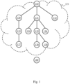
- FIG. 1 schematically illustrates a communication network 121 having a logical topology in the form of a tree deployed on an electrical power supply network and in which the invention can be implemented.
- the communication network 121 is in the form of a tree of which a particular node device 110, called hub device 110 or base node, is the root.
- the communication network 121 is intended to allow a plurality of node devices to be connected to the hub device 110.
- the node devices that the communication network 121 aims to connect are electric meters.
- the communication network 121 thus makes it possible to establish online power line communications so that the concentrator device 110 can in particular automatically carry out readings of electricity consumption metering carried out by the electric meters.
- a signal emitted by a node device is generally not visible at every point of said communication network.
- Each signal-emitting node device then has a "neighborhood domain", i.e. a subset of said communication network in which any connected node device can intelligibly receive said signals.
- the neighborhood domain corresponds to the range of the emitted signals, depending on predetermined transmission parameters (e.g. power, modulation and coding scheme, etc.) of the signal-emitting node device and also depending on characteristics of the communication channel (attenuation, noise, impedance, etc.).
- Each node device of said communication network thus has its own neighborhood domain.
- node devices act as data relays between other node devices and the hub device 110.
- a relay device is referred to as a switch in the PRIME specifications.
- Some communications between node devices and the hub device 110 may require multiple data relays. successive.
- a node device not acting as a relay is called a terminal device.
- Such a structure therefore defines connections of node devices to each other to form the tree, i.e. the hierarchy constituting the communication network 121.
- Each node device of the communication network 121 is thus associated with a hierarchical level, typically corresponding to the quantity of relay devices through which said node device must pass to reach the root of the communication network 121.
- the relay devices emit beacons 300, which allow the node devices 130-139 attached to them to synchronize with the communication network 121.
- the sending of these beacons is carried out in respective predefined time intervals.
- the structure of these beacons 300 will be defined below.
- a terminal node device 132 is directly attached to the hub device 110.
- Two other node devices 130 and 131 are also directly attached to the hub device 110. These two node devices 130 and 131 act as relay devices between the hub device 110 and other node devices.
- the node device 130 acts as a relay device between the hub device 110 and a node device 133 which, itself, acts as a relay device between the node device 130 and a terminal device 137.
- the communications between the hub device 110 and the terminal device 137 therefore pass through two successive relay devices, namely the relay devices 130 and 133.
- the node device 131 acts as a relay device between the hub device 110 and three other node devices 134, 135 and 136.
- the node devices 134 and 136 are terminal devices, and the node device 135 acts as a relay device between the node device 131 and two terminal devices 138 and 139.
- the node devices 130, 131 and 132 are associated with a hierarchical level of value “0”
- the node devices 133, 134, 135, 136 are associated with a hierarchical level of value “1”, and so on.
- a node device that is not attached to the communications network 121 is a disconnected device, such as the node device 140 on the Fig. 1 .
- Fig. 1 represents the logical topology of the communication network 121 at a given time. Due in particular to interference phenomena (such as noise, attenuation, impedance variation, crosstalk, signal collision, etc.), devices nodes may find themselves disconnected from the communication network 121 and then seek to re-register within the communication network 121. The logical topology of the communication network 121 at that time is then probably different from the logical topology of the communication network 121 before disconnection of said node devices, node devices having then potentially been stripped of their relay role and others having then potentially been promoted to play the relay role.
- interference phenomena such as noise, attenuation, impedance variation, crosstalk, signal collision, etc.
- the promotion of a node device 130-139 to a relay device is carried out by sending a promotion request 400 ( Promotion Needed Protocol Data Unit in English, abbreviated to PNPDU), from a node device which seeks to connect to the communication network 121 and which does not have a relay device as a neighbor, such as the node device 140, to the node device 130-139 to be promoted to a relay device.
- a promotion request 400 Promotion Needed Protocol Data Unit in English, abbreviated to PNPDU
- PNPDU Promotion Needed Protocol Data Unit in English, abbreviated to PNPDU
- the hub device 110 uses one version of a communication protocol to transmit information to all of the node devices 130-139 of the communication network 121.
- the hub device 110 changes the version of the communication protocol, it sends a network access firmware switching order to all of the node devices 130-139.
- the node devices 130-139 then switch to another firmware version that implements the new version of the communication protocol used by the hub device 110.
- the node device then risks no longer receiving the frames transmitted by the hub device and being disconnected from the communication network. To avoid this problem, the control and switching method detailed below is proposed.
- a method 1 for controlling and switching the version of a firmware for accessing the communication network 121 is proposed.
- each node device 130-140 of the communication network 121 comprises electronic circuitry 200 allowing it to implement the method 1.
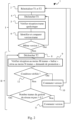
- method 1 mainly comprises a first phase I and a second phase II.
- the method 1 comprises a step 4 consisting of triggering a first time delay. Then, the method 1 comprises a step 5 consisting of verifying, during the first time delay T1, the reception of any frame transmitted by the concentrator device 110 and/or another node device (130-140) acting as a relay device or as a terminal device. The any frame making it possible to identify a version of the communication protocol used by the concentrator device 110.
- the node device 130-140 listens to the communication network 121 and receives any frame sent by the concentrator device 110 and/or another node device (130-140) acting as a relay device or as a terminal device.
- each frame transmitted by the concentrator device 110 comprises information making it possible to identify the version of the communication protocol used by the concentrator device 110 (or by a node device (130-140) acting as a relay device or as a terminal device).
- the method 1 comprises a step 6, in which the node device 130-140 identifies the version of the communication protocol used by the hub device 110 and compares a version of the firmware used by the node device 130-140 and the version of the communication protocol used by the hub device 110.
- the comparison comprises determining whether the version of the firmware used by the node device 130-140 implements, or not, the version of the communication protocol used by the hub device 110.
- the comparison in step 6 may consist, for the node device 130-140, of determining whether it can read the frame, or not. If the node device 130-140 can read any frame, then it uses the firmware version that implements the version of the communication protocol used by the hub device 110. On the contrary, if it appears that the frame is unreadable by the node device 130-140, then it is because the node device 130-140 is using a version of the firmware which does not implement the version of the communication protocol used by the hub device 110.
- the node device 130-140 repeats the first phase I.
- the node device 130-140 If the firmware version used by the node device 130-140 does not implement the version of the communication protocol used by the hub device 110, then the node device 130-140 triggers the second phase II of the method 1.
- the second phase II comprises a step 8 which consists of triggering a second time delay T2. Then, the second phase II comprises a step 9 which consists of verifying during the second time delay T2, the reception of network management frames transmitted by the concentrator device 110 or by another node device 130-140 acting as a relay device between the concentrator device 110 and the node device 130-140 or by another node device 130-140 acting as a terminal device.
- the network management frames make it possible to identify a version of the communication protocol used by the hub device 110 or by another node device (130-140) acting as a relay device or as a terminal device.
- the node device 130-139 listens precisely to the network management frames transmitted by the hub device 110 or another node device 130-140.
- the analysis of certain bit fields in the structure of the network management frames makes it possible to know precisely the version of the communication protocol used.
- the node device 130-140 verifies the reception of management frames sent by several devices connected to the communication network 121.
- the device Node 130-140 listens for network management frames sent from several different sources.
- the method 1 comprises a step 10 of switching the node device 130-140 to another firmware version which implements the version of the communication protocol used by the hub device 110 and/or another node device 130-140. Then the node device 130-140 repeats the first phase I of the method 1.
- the node device 130-140 repeats the first phase I of the method by resetting the first time delay T1 (step 2).
- the first time delay T1 can be reset to have a duration of 6 hours.
- the analysis of a first predetermined number M of management frames of the “beacon” type 300 and of a second predetermined number N of management frames of the “promotion request” type 400 received on the second time delay T2 is a particularly advantageous technical arrangement of the invention. Indeed, this arrangement makes it possible to ensure that most of the network management frames received during the second time delay T2, indeed indicate the same communication protocol version used by the concentrator device 110 and/or another node device 130-140. In other words, this arrangement makes it possible to prevent a one-off error in the transmission of a network management frame from triggering a change of firmware version by the node device 130-140.
- the first predetermined number M can be a positive integer between 5 and 11 and more particularly between 7 and 9 inclusive and the second predetermined number N can be a positive integer between 4 and 9 and more particularly between 5 and 7.
- the node device 130-140 repeats the second phase II of method 1.
- step 11 which consists of switching to another firmware version. Then the method 1 repeats the first phase I by resetting the first timer T1. Typically the first timer T1 can be reset to have a duration of one hour. In other words, step 11 is executed if the node device 130-139 does not receive any network management frame. In this case, and according to the operating principle of the PRIME type communication network which was explained above, it is likely that the node device 130-140 has been disconnected from the communication network. Consequently, the node device 130-139 changes its firmware version to be reconnected to the communication network 121. Then the node device 130-140 repeats the phase I by resetting the first timer T1 to a short duration. This allows for rapid error detection. Indeed, the firmware version change must allow the node device 130-140 to be reconnected to the communication network 121, so that the node device 130-139 will necessarily receive at least one frame during the first time delay T1.
- the method 1 can comprise a prior step 2 of initializing each time delay T1 and T2.
- the first time delay T1 can for example be defined as being equal to 6 hours.
- the second time delay T2 can for example be defined as being equal to 1 hour.
- the network management frames received and used are preferably of the “beacon” type 300 or of the “promotion request” type 400, as described previously.
- the method 1 according to the invention uses particular knowledge of the structures of the network management frames of the “beacon” type 300 and of the “promotion request” type 400, to determine the version of the communication protocol used to send the network management frames of type “beacon” 300 and type “promotion request” 400.
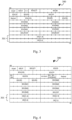
- FIG. 3 schematically illustrates the structure of a network management frame of type “beacon” 300 sent using a first version of the communication protocol on the communication network 121.
- FIG. 4 schematically illustrates the structure of a network management frame of type "beacon" 300 sent using a second version of the communication protocol on the communication network 121.
- each network management frame of the “beacon” type 300 has a bit field 301 which is a result of a cyclic CRC redundancy check whose value indicates the version of the communication protocol used by the concentrator device 110 and/or the relay device.
- each network management frame of type "beacon" 300 comprises a payload.
- the payloads have the same number of bytes.
- the payloads differ in terms of the location and/or the number of bits of the following fields: BCN.LEVEL, BCN.POS, BCN.COST, BCN.SEQ and BCN.FRQ. These differences induce differences in the result of the cyclic redundancy check CRC.
- the result of the cyclic redundancy check CRC is determined using the entire structure of the network management frame of the “beacon” type 300, with the exception of the result of the cyclic redundancy check CRC itself.
- the result of the CRC cyclic redundancy check is determined using the entire structure of the network management frame of the “beacon” type 300, including the result of the CRC cyclic redundancy check itself to which a default value is assigned for this determination.
- the result of the cyclic redundancy check CRC is identical if the network management frames of type "beacon” 300 frames are sent using the same version of the communication protocol and the result of the cyclic redundancy check CRC differs if the network management frames of type "beacon” 300 are sent using two different versions of the communication protocol.
- FIG. 5 schematically illustrates the structure of a network management frame of type “promotion request” 400 sent using a first version of the communication protocol on the communication network 121.
- FIG. 6 schematically illustrates the structure of a network management frame of type "promotion request" 400 sent using a second version of the communication protocol on the communication network 121.
- each network management frame of the “promotion request” type 400 has a bit field 401 which is a high-order byte MSB comprising four low-order bits 402, the four low-order bits 402 being used to indicate the version of the communication protocol used by the hub device and/or another node device (130-139) acting as a relay device or acting as a terminal device. More precisely, the four low-order bits are said to be reserved . Thus, it is possible to use two bits out of these four bits to distinguish two versions of the communication protocol. According to a particular arrangement, the two bits used are the PNH.VER bits. Thus, according to a first version of the communication protocol, the two PNH.VER bits can be equal to 00 and according to a second version the two PNH.VER bits can be equal to 01.
- a node device 130-139 comprising electronic circuitry 200 for performing method 1.
- a computer system 200 comprising electronic circuitry configured to implement a method 100 for controlling and switching the version of firmware for access to a communication network.
- the computer system 200 may comprise, connected by a communication bus 210: a processor 201; a random access memory 202; a read-only memory 203, for example of the ROM (“Read Only Memory” in English) or EEPROM (“Electrically-Erasable Programmable Read Only Memory” in English) type; a storage unit 204, such as a hard disk HDD (“Hard Disk Drive” in English), or a storage media reader, such as an SD (“Secure Digital” in English) card reader; and an input-output interface manager 205.
- a processor 201 a random access memory 202
- a read-only memory 203 for example of the ROM (“Read Only Memory” in English) or EEPROM (“Electrically-Erasable Programmable Read Only Memory” in English) type
- a storage unit 204 such as a hard disk HDD (“Hard Disk Drive” in English), or a storage media reader, such as an SD (“Secure Digital” in English) card reader
Landscapes
- Engineering & Computer Science (AREA)
- Computer Networks & Wireless Communication (AREA)
- Signal Processing (AREA)
- Software Systems (AREA)
- General Engineering & Computer Science (AREA)
- Theoretical Computer Science (AREA)
- Computer Security & Cryptography (AREA)
- Physics & Mathematics (AREA)
- General Physics & Mathematics (AREA)
- Power Engineering (AREA)
- Small-Scale Networks (AREA)
Claims (12)
- Verfahren (1) zur Versionsprüfung und -umschaltung einer Firmware für den Zugang zu einem Kommunikationsnetzwerk (121), das eine logische Topologie in Form eines Baums aus Knotenvorrichtungen (130-139) hat und das in ein Stromversorgungsnetz implementiert ist, wobei das Kommunikationsnetzwerk (121) eine Konzentratorvorrichtung (110) umfasst, wobei das Verfahren von einer Knotenvorrichtung (130-139) implementiert wird, die eine elektronische Schaltungsanordnung (200) umfasst, und wobei das Verfahren dadurch gekennzeichnet ist, dass es eine erste Phase (I) umfasst, welche die folgenden Schritte umfasst:- Auslösen (4) einer ersten Verzögerung (Tl) und Überprüfen (5) des Empfangens, während der ersten Verzögerung (T1), eines beliebigen Rahmens, der es ermöglicht, eine von der Konzentratorvorrichtung (110) verwendete Version des Kommunikationsprotokolls zu ermitteln;- wenn die von der Knotenvorrichtung (130-139) verwendete Version der Firmware die von der Konzentratorvorrichtung (110) verwendete Version des Kommunikationsprotokolls implementiert, Wiederholen der ersten Phase (I), ansonsten Auslösen einer zweiten Phase (II), welche die folgenden Schritte umfasst:- Auslösen (8) einer zweiten Verzögerung (T2) und Überprüfen (9) des Empfangens, während der zweiten Verzögerung (T2), von Netzwerkverwaltungsrahmen vom Typ "Beacon", die von der Konzentratorvorrichtung (110) oder von einer anderen Knotenvorrichtung (130-140) gesendet werden, und/oder von Netzwerkverwaltungsrahmen vom Typ "Promotion Request", die von einer anderen Knotenvorrichtung (130-140) gesendet werden, wobei die Netzwerkverwaltungsrahmen es ermöglichen, eine verwendete Version des Kommunikationsprotokolls zu ermitteln;- wenn eine vorbestimmte erste Anzahl M von empfangenen Netzwerkverwaltungsrahmen vom Typ "Beacon" und/oder eine vorbestimmte zweite Anzahl N von empfangenen Netzwerkverwaltungsrahmen vom Typ "Promotion Request" es ermöglichen, eine von der Konzentratorvorrichtung (110) oder von einer anderen Knotenvorrichtung (130-140) verwendete Version des Kommunikationsprotokolls zu ermitteln, die von der von der Knotenvorrichtung (130-140) verwendeten Version der Firmware nicht implementiert ist, Umschalten (10) der Knotenvorrichtung (130-140) auf eine andere Version der Firmware, welche die von der Konzentratorvorrichtung (110) oder von der Relaisvorrichtung verwendete Version des Kommunikationsprotokolls implementiert, dann Wiederholen der ersten Phase (I);- wenn eine Anzahl von empfangenen Netzwerkverwaltungsrahmen vom Typ "Beacon" strikt größer als null und strikt kleiner als die vorbestimmte erste Anzahl M ist und wenn eine Anzahl von empfangenen Netzwerkverwaltungsrahmen vom Typ "Promotion Request" strikt größer als null und strikt kleiner als die vorbestimmte zweite Anzahl N ist, Wiederholen der zweiten Phase (II);- wenn kein Netzwerkverwaltungsrahmen empfangen wird, Umschalten (11) auf eine andere Version der Firmware, dann Wiederholen der ersten Phase (I).
- Verfahren (1) nach Anspruch 1, wobei jeder Netzwerkverwaltungsrahmen ein Bit-Feld (301, 401) umfasst, dessen Wert je nach verwendeter Version des Kommunikationsprotokolls vorgegeben ist, so dass der Wert des Bit-Felds (301, 402) die von der Konzentratorvorrichtung (110) und/oder einer anderen Knotenvorrichtung (130-140) verwendete Version des Kommunikationsprotokolls angibt.
- Verfahren (1) nach einem der Ansprüche 1 oder 2, wobei die empfangenen Netzwerkverwaltungsrahmen, die vom Typ "Beacon" (300) sind, vorgegebene Zeitintervalle von Rahmen sind, die in dem Kommunikationsnetzwerk (121) übertragen werden und es sämtlichen Knotenvorrichtungen (130-139) ermöglichen, sich mit der Konzentratorvorrichtung (110) zu synchronisieren.
- Verfahren (1) nach Anspruch 3, wobei das Bit-Feld (301) ein Ergebnis einer zyklischen Redundanzprüfung ist, dessen Wert die von der Konzentratorvorrichtung (110) und/oder einer anderen Knotenvorrichtung (130-140) verwendete Version des Kommunikationsprotokolls angibt.
- Verfahren (1) nach einem der Ansprüche 1 oder 2, wobei die empfangenen Netzwerkverwaltungsrahmen, die vom Typ "Promotion Request" (400) sind, vorgegebene Zeitintervalle von Rahmen sind, die in dem Kommunikationsnetzwerk übertragen werden und es der Konzentratorvorrichtung (110) ermöglichen, eine Knotenvorrichtung (130-139) in eine Relaisvorrichtung umzuwandeln.
- Verfahren (1) nach Anspruch 5, wobei das Bit-Feld (401) ein höchstwertiges Byte ist, das vier niedrigstwertige Bits (402) umfasst, wobei die vier niedrigstwertigen Bits (402) verwendet werden, um die von der Konzentratorvorrichtung (110) und/oder einer anderen Knotenvorrichtung (130-140) verwendete Version des Kommunikationsprotokolls anzugeben.
- Verfahren nach einem der vorhergehenden Ansprüche, wobei bei der zweiten Phase (II), wenn kein Netzwerkverwaltungsrahmen empfangen wird, die Knotenvorrichtung auf eine andere Version der Firmware umschaltet (11), welche die von der Konzentratorvorrichtung (110) verwendete Version des Kommunikationsprotokolls implementiert, dann die erste Phase (I) wiederholt, wobei die erste Verzögerung (T1) gemäß einem vorbestimmten Wert reinitialisiert wird.
- Verfahren (1) nach einem der vorhergehenden Ansprüche, umfassend einen vorherigen Schritt des Initialisierens der ersten Verzögerung (T1) und der zweiten Verzögerung (T2) gemäß vorbestimmten Werten.
- Verfahren (1) nach einem der vorhergehenden Ansprüche, wobei der Schritt, der darin besteht, das Empfangen, während der zweiten Verzögerung (T2), von Netzwerkverwaltungsrahmen zu überprüfen (9), ausgeführt wird, indem das Empfangen von Netzwerkverwaltungsrahmen überprüft wird, die von einer Mehrzahl von Vorrichtungen des Kommunikationsnetzwerks gesendet werden.
- Knotenvorrichtung (130-139), umfassend eine elektronische Schaltungsanordnung (200) zum Ausführen des Verfahrens (1) nach einem der Ansprüche 1 bis 9.
- Computerprogrammprodukt, das Programmcodeanweisungen umfasst, die bei der Ausführung der Anweisungen durch mindestens einen Prozessor (201) das Verfahren (1) nach einem der Ansprüche 1 bis 9 ausführen.
- Medium zur nichtflüchtigen Speicherung, auf dem ein Computerprogramm gespeichert ist, das Programmcodeanweisungen umfasst, die beim Lesen der Anweisungen von dem Medium zur nichtflüchtigen Speicherung und Ausführen durch einen Prozessor (201) das Verfahren (1) nach einem der Ansprüche 1 bis 9 ausführen.
Applications Claiming Priority (1)
| Application Number | Priority Date | Filing Date | Title |
|---|---|---|---|
| FR2300668A FR3145252A1 (fr) | 2023-01-25 | 2023-01-25 | Procede de controle et de commutation d’un micrologiciel |
Publications (2)
| Publication Number | Publication Date |
|---|---|
| EP4407879A1 EP4407879A1 (de) | 2024-07-31 |
| EP4407879B1 true EP4407879B1 (de) | 2025-05-07 |
Family
ID=86469024
Family Applications (1)
| Application Number | Title | Priority Date | Filing Date |
|---|---|---|---|
| EP24153578.0A Active EP4407879B1 (de) | 2023-01-25 | 2024-01-24 | Verfahren zur steuerung und umschaltung von firmware |
Country Status (6)
| Country | Link |
|---|---|
| US (1) | US20240250872A1 (de) |
| EP (1) | EP4407879B1 (de) |
| CN (1) | CN118400262A (de) |
| ES (1) | ES3036766T3 (de) |
| FR (1) | FR3145252A1 (de) |
| PL (1) | PL4407879T3 (de) |
Family Cites Families (2)
| Publication number | Priority date | Publication date | Assignee | Title |
|---|---|---|---|---|
| US20140056369A1 (en) * | 2012-08-21 | 2014-02-27 | Texas Instruments Incorporated | Control Traffic Overhead Reduction during Network Setup in PLC Networks |
| US10686914B2 (en) * | 2014-11-04 | 2020-06-16 | Texas Instruments Incorporated | Automatic selection of MAC protocol to support multiple prime PLC standards |
-
2023
- 2023-01-25 FR FR2300668A patent/FR3145252A1/fr not_active Ceased
-
2024
- 2024-01-17 US US18/415,241 patent/US20240250872A1/en active Pending
- 2024-01-23 CN CN202410094170.4A patent/CN118400262A/zh active Pending
- 2024-01-24 ES ES24153578T patent/ES3036766T3/es active Active
- 2024-01-24 PL PL24153578.0T patent/PL4407879T3/pl unknown
- 2024-01-24 EP EP24153578.0A patent/EP4407879B1/de active Active
Also Published As
| Publication number | Publication date |
|---|---|
| US20240250872A1 (en) | 2024-07-25 |
| FR3145252A1 (fr) | 2024-07-26 |
| EP4407879A1 (de) | 2024-07-31 |
| PL4407879T3 (pl) | 2025-09-08 |
| CN118400262A (zh) | 2024-07-26 |
| ES3036766T3 (en) | 2025-09-24 |
Similar Documents
| Publication | Publication Date | Title |
|---|---|---|
| EP2294799B1 (de) | Verfahren und einrichtung zum vergeben von mac-adressen in einem trägeraktuellen kommunikationsnetz | |
| EP3182281B1 (de) | Übertragungsverfahren einer neuen software-version an mindestens einen stromzähler über ein kommunikationsnetz | |
| EP3526952B1 (de) | Relais in einem lpwan-art-kommunikationssystem | |
| EP2894872B1 (de) | Verfahren zur Verlaufsplanung der Aufgaben in einem PLC-Netz | |
| EP3934108B1 (de) | Verfahren zur bestimmung eines kommunikationsmodus zwischen zwei benachbarten geräten in einem netzwerk | |
| EP4407879B1 (de) | Verfahren zur steuerung und umschaltung von firmware | |
| EP2206331B1 (de) | Umkonfiguration von netzwerkabschlusseinrichtungen | |
| EP2811262B1 (de) | Verfahren zur Auswahl des Anschlusses eines elektrischen Zählers an einen anderen elektrischen Zähler oder an einen Datenkonzentrator | |
| EP3504932B1 (de) | Verfahren zur steuerung der last eines datenkonzentrationsgateways für ein drahtloskommunikationsnetzwerk | |
| EP3520322B1 (de) | Verfahren und vorrichtung zum remote-aufwecken einer mit einem netzwerk verbundenen vorrichtung | |
| WO2020002376A1 (fr) | Procede de gestion d'une connexion dans un reseau sans fil distribue | |
| EP4184936B1 (de) | Verfahren zur wiederverbindung eines intelligenten stromzählers und intelligenter stromzähler, der dieses verfahren umsetzt | |
| EP4668715A1 (de) | Verfahren zur konfiguration eines kommunikationsprotokolls einer knotenvorrichtung | |
| EP3934110B1 (de) | Verfahren und vorrichtung zur übertragung einer nachricht | |
| FR3112262A1 (fr) | Procede de regulation destine a resorber un engorgement d’un reseau maille de communication par courants porteurs en ligne | |
| WO2025131629A1 (fr) | Découverte d'un réseau de synchronisation au sein d'un réseau d'équipements | |
| EP4704409A1 (de) | Verfahren zur kommunikation in einem gemischten kommunikationsnetzwerk über eine protokollübersetzungseinrichtung | |
| EP3211841B1 (de) | Verfahren zum entscheiden über die weiterleitung einer kopie einer wegermittlungsanfrage durch übertragung in einem kommunikationsnetz | |
| EP3122006B1 (de) | Verfahren zur auswahl einer elternknoten-vorrichtung in einem baumförmigen kommunikationsnetz | |
| EP3104566B1 (de) | Auswahlverfahren einer modulation bei übertragungen von frames über online-trägerströme | |
| EP2517412B1 (de) | Sicherungsvorrichtung einer upnp-steuerung | |
| EP2372959B1 (de) | Method and network for data packet transmission between at least two electronic devices. | |
| FR3031645A1 (fr) | Procede d'allocation de ressources pour l'envoi de balises dans un reseau de communication | |
| WO2016092197A1 (fr) | Procédé de gestion d'un réseau de nœuds de calcul | |
| FR3069398A1 (fr) | Procede de commutation de trames |
Legal Events
| Date | Code | Title | Description |
|---|---|---|---|
| PUAI | Public reference made under article 153(3) epc to a published international application that has entered the european phase |
Free format text: ORIGINAL CODE: 0009012 |
|
| STAA | Information on the status of an ep patent application or granted ep patent |
Free format text: STATUS: EXAMINATION IS IN PROGRESS |
|
| 17P | Request for examination filed |
Effective date: 20240124 |
|
| AK | Designated contracting states |
Kind code of ref document: A1 Designated state(s): AL AT BE BG CH CY CZ DE DK EE ES FI FR GB GR HR HU IE IS IT LI LT LU LV MC ME MK MT NL NO PL PT RO RS SE SI SK SM TR |
|
| GRAP | Despatch of communication of intention to grant a patent |
Free format text: ORIGINAL CODE: EPIDOSNIGR1 |
|
| STAA | Information on the status of an ep patent application or granted ep patent |
Free format text: STATUS: GRANT OF PATENT IS INTENDED |
|
| INTG | Intention to grant announced |
Effective date: 20241213 |
|
| GRAS | Grant fee paid |
Free format text: ORIGINAL CODE: EPIDOSNIGR3 |
|
| GRAA | (expected) grant |
Free format text: ORIGINAL CODE: 0009210 |
|
| STAA | Information on the status of an ep patent application or granted ep patent |
Free format text: STATUS: THE PATENT HAS BEEN GRANTED |
|
| AK | Designated contracting states |
Kind code of ref document: B1 Designated state(s): AL AT BE BG CH CY CZ DE DK EE ES FI FR GB GR HR HU IE IS IT LI LT LU LV MC ME MK MT NL NO PL PT RO RS SE SI SK SM TR |
|
| REG | Reference to a national code |
Ref country code: GB Ref legal event code: FG4D Free format text: NOT ENGLISH |
|
| REG | Reference to a national code |
Ref country code: CH Ref legal event code: EP |
|
| REG | Reference to a national code |
Ref country code: DE Ref legal event code: R096 Ref document number: 602024000097 Country of ref document: DE |
|
| REG | Reference to a national code |
Ref country code: IE Ref legal event code: FG4D Free format text: LANGUAGE OF EP DOCUMENT: FRENCH |
|
| REG | Reference to a national code |
Ref country code: NL Ref legal event code: MP Effective date: 20250507 |
|
| REG | Reference to a national code |
Ref country code: ES Ref legal event code: FG2A Ref document number: 3036766 Country of ref document: ES Kind code of ref document: T3 Effective date: 20250924 |
|
| PG25 | Lapsed in a contracting state [announced via postgrant information from national office to epo] |
Ref country code: FI Free format text: LAPSE BECAUSE OF FAILURE TO SUBMIT A TRANSLATION OF THE DESCRIPTION OR TO PAY THE FEE WITHIN THE PRESCRIBED TIME-LIMIT Effective date: 20250507 Ref country code: PT Free format text: LAPSE BECAUSE OF FAILURE TO SUBMIT A TRANSLATION OF THE DESCRIPTION OR TO PAY THE FEE WITHIN THE PRESCRIBED TIME-LIMIT Effective date: 20250908 |
|
| REG | Reference to a national code |
Ref country code: LT Ref legal event code: MG9D |
|
| PG25 | Lapsed in a contracting state [announced via postgrant information from national office to epo] |
Ref country code: NO Free format text: LAPSE BECAUSE OF FAILURE TO SUBMIT A TRANSLATION OF THE DESCRIPTION OR TO PAY THE FEE WITHIN THE PRESCRIBED TIME-LIMIT Effective date: 20250807 Ref country code: GR Free format text: LAPSE BECAUSE OF FAILURE TO SUBMIT A TRANSLATION OF THE DESCRIPTION OR TO PAY THE FEE WITHIN THE PRESCRIBED TIME-LIMIT Effective date: 20250808 |
|
| PG25 | Lapsed in a contracting state [announced via postgrant information from national office to epo] |
Ref country code: NL Free format text: LAPSE BECAUSE OF FAILURE TO SUBMIT A TRANSLATION OF THE DESCRIPTION OR TO PAY THE FEE WITHIN THE PRESCRIBED TIME-LIMIT Effective date: 20250507 |
|
| REG | Reference to a national code |
Ref country code: AT Ref legal event code: MK05 Ref document number: 1793643 Country of ref document: AT Kind code of ref document: T Effective date: 20250507 |
|
| PG25 | Lapsed in a contracting state [announced via postgrant information from national office to epo] |
Ref country code: BG Free format text: LAPSE BECAUSE OF FAILURE TO SUBMIT A TRANSLATION OF THE DESCRIPTION OR TO PAY THE FEE WITHIN THE PRESCRIBED TIME-LIMIT Effective date: 20250507 |
|
| PG25 | Lapsed in a contracting state [announced via postgrant information from national office to epo] |
Ref country code: HR Free format text: LAPSE BECAUSE OF FAILURE TO SUBMIT A TRANSLATION OF THE DESCRIPTION OR TO PAY THE FEE WITHIN THE PRESCRIBED TIME-LIMIT Effective date: 20250507 |
|
| PG25 | Lapsed in a contracting state [announced via postgrant information from national office to epo] |
Ref country code: AT Free format text: LAPSE BECAUSE OF FAILURE TO SUBMIT A TRANSLATION OF THE DESCRIPTION OR TO PAY THE FEE WITHIN THE PRESCRIBED TIME-LIMIT Effective date: 20250507 |
|
| PG25 | Lapsed in a contracting state [announced via postgrant information from national office to epo] |
Ref country code: RS Free format text: LAPSE BECAUSE OF FAILURE TO SUBMIT A TRANSLATION OF THE DESCRIPTION OR TO PAY THE FEE WITHIN THE PRESCRIBED TIME-LIMIT Effective date: 20250807 |
|
| PG25 | Lapsed in a contracting state [announced via postgrant information from national office to epo] |
Ref country code: IS Free format text: LAPSE BECAUSE OF FAILURE TO SUBMIT A TRANSLATION OF THE DESCRIPTION OR TO PAY THE FEE WITHIN THE PRESCRIBED TIME-LIMIT Effective date: 20250907 |
|
| PG25 | Lapsed in a contracting state [announced via postgrant information from national office to epo] |
Ref country code: LV Free format text: LAPSE BECAUSE OF FAILURE TO SUBMIT A TRANSLATION OF THE DESCRIPTION OR TO PAY THE FEE WITHIN THE PRESCRIBED TIME-LIMIT Effective date: 20250507 |
|
| PG25 | Lapsed in a contracting state [announced via postgrant information from national office to epo] |
Ref country code: DK Free format text: LAPSE BECAUSE OF FAILURE TO SUBMIT A TRANSLATION OF THE DESCRIPTION OR TO PAY THE FEE WITHIN THE PRESCRIBED TIME-LIMIT Effective date: 20250507 Ref country code: SM Free format text: LAPSE BECAUSE OF FAILURE TO SUBMIT A TRANSLATION OF THE DESCRIPTION OR TO PAY THE FEE WITHIN THE PRESCRIBED TIME-LIMIT Effective date: 20250507 |
|
| PG25 | Lapsed in a contracting state [announced via postgrant information from national office to epo] |
Ref country code: CZ Free format text: LAPSE BECAUSE OF FAILURE TO SUBMIT A TRANSLATION OF THE DESCRIPTION OR TO PAY THE FEE WITHIN THE PRESCRIBED TIME-LIMIT Effective date: 20250507 |
|
| PGFP | Annual fee paid to national office [announced via postgrant information from national office to epo] |
Ref country code: PL Payment date: 20251218 Year of fee payment: 3 |
|
| PG25 | Lapsed in a contracting state [announced via postgrant information from national office to epo] |
Ref country code: EE Free format text: LAPSE BECAUSE OF FAILURE TO SUBMIT A TRANSLATION OF THE DESCRIPTION OR TO PAY THE FEE WITHIN THE PRESCRIBED TIME-LIMIT Effective date: 20250507 |
|
| PG25 | Lapsed in a contracting state [announced via postgrant information from national office to epo] |
Ref country code: SK Free format text: LAPSE BECAUSE OF FAILURE TO SUBMIT A TRANSLATION OF THE DESCRIPTION OR TO PAY THE FEE WITHIN THE PRESCRIBED TIME-LIMIT Effective date: 20250507 |
|
| PG25 | Lapsed in a contracting state [announced via postgrant information from national office to epo] |
Ref country code: IT Free format text: LAPSE BECAUSE OF FAILURE TO SUBMIT A TRANSLATION OF THE DESCRIPTION OR TO PAY THE FEE WITHIN THE PRESCRIBED TIME-LIMIT Effective date: 20250507 |
|
| REG | Reference to a national code |
Ref country code: DE Ref legal event code: R097 Ref document number: 602024000097 Country of ref document: DE |
|
| PLBE | No opposition filed within time limit |
Free format text: ORIGINAL CODE: 0009261 |
|
| STAA | Information on the status of an ep patent application or granted ep patent |
Free format text: STATUS: NO OPPOSITION FILED WITHIN TIME LIMIT |
|
| REG | Reference to a national code |
Ref country code: CH Ref legal event code: L10 Free format text: ST27 STATUS EVENT CODE: U-0-0-L10-L00 (AS PROVIDED BY THE NATIONAL OFFICE) Effective date: 20260318 |