EP4407815A2 - System und verfahren für flache elektrische schutzvorrichtungen (gfci, afci und afci/gfci) - Google Patents
System und verfahren für flache elektrische schutzvorrichtungen (gfci, afci und afci/gfci) Download PDFInfo
- Publication number
- EP4407815A2 EP4407815A2 EP24180288.3A EP24180288A EP4407815A2 EP 4407815 A2 EP4407815 A2 EP 4407815A2 EP 24180288 A EP24180288 A EP 24180288A EP 4407815 A2 EP4407815 A2 EP 4407815A2
- Authority
- EP
- European Patent Office
- Prior art keywords
- solenoid
- lifting shelf
- carriage
- electrical outlet
- movable
- Prior art date
- Legal status (The legal status is an assumption and is not a legal conclusion. Google has not performed a legal analysis and makes no representation as to the accuracy of the status listed.)
- Granted
Links
Images












Classifications
-
- G—PHYSICS
- G01—MEASURING; TESTING
- G01R—MEASURING ELECTRIC VARIABLES; MEASURING MAGNETIC VARIABLES
- G01R11/00—Electromechanical arrangements for measuring time integral of electric power or current, e.g. of consumption
- G01R11/02—Constructional details
- G01R11/04—Housings; Supporting racks; Arrangements of terminals
-
- H—ELECTRICITY
- H01—ELECTRIC ELEMENTS
- H01H—ELECTRIC SWITCHES; RELAYS; SELECTORS; EMERGENCY PROTECTIVE DEVICES
- H01H71/00—Details of the protective switches or relays covered by groups H01H73/00 - H01H83/00
- H01H71/10—Operating or release mechanisms
- H01H71/50—Manual reset mechanisms which may be also used for manual release
- H01H71/505—Latching devices between operating and release mechanism
-
- H—ELECTRICITY
- H01—ELECTRIC ELEMENTS
- H01H—ELECTRIC SWITCHES; RELAYS; SELECTORS; EMERGENCY PROTECTIVE DEVICES
- H01H71/00—Details of the protective switches or relays covered by groups H01H73/00 - H01H83/00
- H01H71/10—Operating or release mechanisms
- H01H71/50—Manual reset mechanisms which may be also used for manual release
- H01H71/58—Manual reset mechanisms which may be also used for manual release actuated by push-button, pull-knob, or slide
-
- H—ELECTRICITY
- H01—ELECTRIC ELEMENTS
- H01H—ELECTRIC SWITCHES; RELAYS; SELECTORS; EMERGENCY PROTECTIVE DEVICES
- H01H83/00—Protective switches, e.g. circuit-breaking switches, or protective relays operated by abnormal electrical conditions otherwise than solely by excess current
- H01H83/02—Protective switches, e.g. circuit-breaking switches, or protective relays operated by abnormal electrical conditions otherwise than solely by excess current operated by earth fault currents
- H01H83/04—Protective switches, e.g. circuit-breaking switches, or protective relays operated by abnormal electrical conditions otherwise than solely by excess current operated by earth fault currents with testing means for indicating the ability of the switch or relay to function properly
-
- H—ELECTRICITY
- H01—ELECTRIC ELEMENTS
- H01R—ELECTRICALLY-CONDUCTIVE CONNECTIONS; STRUCTURAL ASSOCIATIONS OF A PLURALITY OF MUTUALLY-INSULATED ELECTRICAL CONNECTING ELEMENTS; COUPLING DEVICES; CURRENT COLLECTORS
- H01R13/00—Details of coupling devices of the kinds covered by groups H01R12/70 or H01R24/00 - H01R33/00
- H01R13/66—Structural association with built-in electrical component
- H01R13/70—Structural association with built-in electrical component with built-in switch
- H01R13/71—Contact members of coupling parts operating as switch, e.g. linear or rotational movement required after mechanical engagement of coupling part to establish electrical connection
-
- H—ELECTRICITY
- H01—ELECTRIC ELEMENTS
- H01R—ELECTRICALLY-CONDUCTIVE CONNECTIONS; STRUCTURAL ASSOCIATIONS OF A PLURALITY OF MUTUALLY-INSULATED ELECTRICAL CONNECTING ELEMENTS; COUPLING DEVICES; CURRENT COLLECTORS
- H01R13/00—Details of coupling devices of the kinds covered by groups H01R12/70 or H01R24/00 - H01R33/00
- H01R13/66—Structural association with built-in electrical component
- H01R13/70—Structural association with built-in electrical component with built-in switch
- H01R13/713—Structural association with built-in electrical component with built-in switch the switch being a safety switch
- H01R13/7135—Structural association with built-in electrical component with built-in switch the switch being a safety switch with ground fault protector
-
- H—ELECTRICITY
- H01—ELECTRIC ELEMENTS
- H01H—ELECTRIC SWITCHES; RELAYS; SELECTORS; EMERGENCY PROTECTIVE DEVICES
- H01H83/00—Protective switches, e.g. circuit-breaking switches, or protective relays operated by abnormal electrical conditions otherwise than solely by excess current
- H01H83/14—Protective switches, e.g. circuit-breaking switches, or protective relays operated by abnormal electrical conditions otherwise than solely by excess current operated by imbalance of two or more currents or voltages, e.g. for differential protection
- H01H83/144—Protective switches, e.g. circuit-breaking switches, or protective relays operated by abnormal electrical conditions otherwise than solely by excess current operated by imbalance of two or more currents or voltages, e.g. for differential protection with differential transformer
-
- H—ELECTRICITY
- H01—ELECTRIC ELEMENTS
- H01R—ELECTRICALLY-CONDUCTIVE CONNECTIONS; STRUCTURAL ASSOCIATIONS OF A PLURALITY OF MUTUALLY-INSULATED ELECTRICAL CONNECTING ELEMENTS; COUPLING DEVICES; CURRENT COLLECTORS
- H01R13/00—Details of coupling devices of the kinds covered by groups H01R12/70 or H01R24/00 - H01R33/00
- H01R13/66—Structural association with built-in electrical component
- H01R13/70—Structural association with built-in electrical component with built-in switch
- H01R13/713—Structural association with built-in electrical component with built-in switch the switch being a safety switch
-
- H—ELECTRICITY
- H01—ELECTRIC ELEMENTS
- H01R—ELECTRICALLY-CONDUCTIVE CONNECTIONS; STRUCTURAL ASSOCIATIONS OF A PLURALITY OF MUTUALLY-INSULATED ELECTRICAL CONNECTING ELEMENTS; COUPLING DEVICES; CURRENT COLLECTORS
- H01R2103/00—Two poles
-
- H—ELECTRICITY
- H01—ELECTRIC ELEMENTS
- H01R—ELECTRICALLY-CONDUCTIVE CONNECTIONS; STRUCTURAL ASSOCIATIONS OF A PLURALITY OF MUTUALLY-INSULATED ELECTRICAL CONNECTING ELEMENTS; COUPLING DEVICES; CURRENT COLLECTORS
- H01R24/00—Two-part coupling devices, or either of their cooperating parts, characterised by their overall structure
- H01R24/76—Two-part coupling devices, or either of their cooperating parts, characterised by their overall structure with sockets, clips or analogous contacts and secured to apparatus or structure, e.g. to a wall
-
- H—ELECTRICITY
- H01—ELECTRIC ELEMENTS
- H01R—ELECTRICALLY-CONDUCTIVE CONNECTIONS; STRUCTURAL ASSOCIATIONS OF A PLURALITY OF MUTUALLY-INSULATED ELECTRICAL CONNECTING ELEMENTS; COUPLING DEVICES; CURRENT COLLECTORS
- H01R24/00—Two-part coupling devices, or either of their cooperating parts, characterised by their overall structure
- H01R24/76—Two-part coupling devices, or either of their cooperating parts, characterised by their overall structure with sockets, clips or analogous contacts and secured to apparatus or structure, e.g. to a wall
- H01R24/78—Two-part coupling devices, or either of their cooperating parts, characterised by their overall structure with sockets, clips or analogous contacts and secured to apparatus or structure, e.g. to a wall with additional earth or shield contacts
-
- H—ELECTRICITY
- H01—ELECTRIC ELEMENTS
- H01R—ELECTRICALLY-CONDUCTIVE CONNECTIONS; STRUCTURAL ASSOCIATIONS OF A PLURALITY OF MUTUALLY-INSULATED ELECTRICAL CONNECTING ELEMENTS; COUPLING DEVICES; CURRENT COLLECTORS
- H01R25/00—Coupling parts adapted for simultaneous co-operation with two or more identical counterparts, e.g. for distributing energy to two or more circuits
- H01R25/006—Coupling parts adapted for simultaneous co-operation with two or more identical counterparts, e.g. for distributing energy to two or more circuits the coupling part being secured to apparatus or structure, e.g. duplex wall receptacle
Definitions
- Embodiments relate to switched electrical devices, more particularly to circuit interrupting devices.
- Circuit interrupting devices such as ground fault circuit interrupter (GFCI) devices, switch to a "tripped" or unlatched state from a “reset” or latched state when one or more conditions is detected.
- GFCI devices having contacts that are biased toward the open position require a latching mechanism for setting and holding the contacts in a closed position.
- switched electrical devices having contacts that are biased toward the closed position require a latching mechanism for setting and holding the contacts in an open position.
- Examples of conventional types of devices include devices of the circuit interrupting type, such as circuit breakers, arc fault interrupters, and GFCIs, to name a few.
- ground fault protection circuitry i.e., GFCI receptacles.
- Such protection circuitry and the associated mechanisms normally take up a substantial amount of the physical space within a receptacle housing, the size of which is limited by the standard junction boxes in which they must fit.
- the embodiments disclosed in the present application attempt to solve these problems by providing more compact devices, allowing for shallower receptacles and more space for other elements and/or features.
- an electrical outlet receptacle comprises a housing including a face plate and a plurality of sensing cores each configured to receive a current flow through a center cavity.
- the current flow defines a current flow direction through the center cavity, wherein the current flow direction is parallel to the face plate, and the plurality of sensing cores are placed symmetrically in a translational direction across the electrical outlet receptacle.
- an electrical outlet receptacle comprises a housing including a face plate and a sensing core configured to receive a current flow through a center cavity.
- the current flow defines a current flow direction through the center cavity of the sensing core, wherein the current flow direction is parallel to the face plate.
- an electrical outlet receptacle comprises a circuit board defining a first plane, a set of fixed contacts, a set of movable contacts, a solenoid having a central axis perpendicular to the first plane, a carriage movable axially along the solenoid and configured to interact with the set of movable contacts, a lifting shelf slidably coupled to a slot in the carriage and movable in a translational direction perpendicular to the central axis of the solenoid, a slide mechanism coupled to the lifting shelf and movable in the translational direction of the lifting shelf, a reset plunger with a portion extending through a first end of the solenoid and axially movable therein, and an armature movable axially along the portion of the reset plunger extending through the solenoid.
- the circuit board includes at least one contact pad.
- the solenoid includes a second end opposite the first end.
- the carriage is adapted to advance the set of movable contacts to form electrical communication with the set of fixed contacts during resetting of the electrical outlet receptacle.
- the lifting shelf includes a latching portion.
- the slide mechanism includes a cam surface to transform a downward force to a translational force applied to the coupled lifting shelf.
- the reset plunger includes an intermediate collar configured to engage to the latching portion of the lifting shelf.
- the armature includes a slanted projection configured to contact the cam surface of the slide mechanism and provide the downward force on the cam surface.
- Exemplary embodiments of devices consistent with the present application include one or more of the novel mechanical and/or electrical features described in detail below.
- Such features may include a compactly positioned sensing core, a vertical solenoid, and a latching mechanism including a lifting shelf, a slide mechanism, an intermediate collar, and a cam surface.
- a vertical solenoid including a lifting shelf, a slide mechanism, an intermediate collar, and a cam surface.
- a latching mechanism including a lifting shelf, a slide mechanism, an intermediate collar, and a cam surface.
- multiple features listed above are incorporated into one element whereas in other exemplary embodiments, each feature is distinct from one another and coupled to interact with each other.
- the novel mechanical and/or electrical features detailed herein efficiently utilize the space within the device housing to provide more area for additional features and/or components.
- FIG. 1 illustrates a perspective view of a GFCI receptacle 10 according to one embodiment of the application.
- the GFCI receptacle 10 includes a front cover 12 having an outlet face 14 with phase 16, neutral 18, and ground 20 openings.
- the outlet face 14 also has a central opening 22 for a reset button 24 adjacent to an opening 26 for a test button 28.
- Rear cover 36 is secured to front cover 12 by screws (not shown or enumerated). Screw terminals 38 mechanically and/or electrically couple wires when wiring the receptacle 10.
- a ground yoke/bridge assembly 40 includes standard mounting ears 42 that protrude from the ends of the receptacle 10.
- the GFCI receptacle 10 with the front cover 12, rear cover 36, and tamper-resistant mechanisms (not enumerated) removed shows phase terminal 30, neutral terminal 32, ground terminal 34, and a circuit board 58.
- the phase, neutral, and ground terminals 30, 32, 34 are respectively configured to receive electrical plugs 35 of a connecting electrical device, such as a power cord.
- the circuit board 58 provides control and physical support for most of the working components of the receptacle 10.
- the phase and neutral terminals 30, 32 may be movable, supported and energized through bus bars 44, 46, respectively. Bus bars 44, 46 act as cantilevered arms that support a set of contacts 48. As shown in the embodiment of FIG.
- the set of contacts 48 include a set of movable contacts 48A and a set of fixed contacts 48B.
- Bus bars 44, 46 respectively serve as cantilevered support for the set of movable contacts 48A while the set of fixed contacts 48B is supported by a carrier assembly 8.
- an indicator light L may be included in the GFCI receptacle 10 and configured to indicate the state of the GFCI receptacle 10.
- a latching mechanism including a movable carriage is used to engage with the set of movable contacts 48A, thereby pushing the set of movable contacts 48A in an upward direction to engage the set of fixed contacts 48B in a closed position during resetting of the GFCI receptacle 10.
- This upward movement of the set of movable contacts 48A also causes corresponding upward movement in the attached phase and neutral terminals 30, 32 closer to the front cover 12 of the receptacle 10. Electricity may then be delivered from an external power source to the receptacle openings 16, 18, 20.
- the resiliency of the cantilevered bus bars 44, 46 may bias the set of movable contacts 48A toward the set of fixed contacts 48B, and a latching mechanism may be employed in reverse to engage and hold the set of movable contacts 48A away from the set of fixed contacts 48B in an open position during tripping of the GFCI receptacle 10.
- the phase and neutral terminals 30, 32 will likewise increase in distance from the front cover 12, thereby prohibiting the flow of electricity between the external power source and the receptacle openings 16, 18, 20.
- Various embodiments of the latching mechanism may be used by various application designs, the details of each are not disclosed in detail herein.
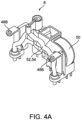
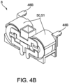
- the carrier assembly 8 in addition to providing structural support for the set of fixed contacts 48B, the carrier assembly 8 also provides structural support for a sense transformer core 50 and conductor windings 52, 54. In another embodiment shown in FIG. 4B , the carrier assembly 8 may provide structural support for multiple sets of sense transformer cores 50, 51, as described in further detail below. Various placements of sense transformer core(s) 50, 51 may be possible and will be further described in the following figures.
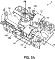
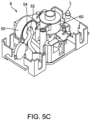
- FIG. 5A illustrates a perspective view of a core assembly 2 of the GFCI receptacle 10 depicted in FIG. 1 .
- a solenoid 60 is oriented to define a central axis A.
- Multiple sense transformer cores 50 may be stacked together and configured to receive a phase conductor winding 52 and a neutral conductor winding 54 through a common central cavity 56. Additional sets of stacked sense transformer cores 51 may be added to the carrier assembly 8 (see FIG. 4B ) to provide further measurements, such as arc fault measurements, to the GFCI receptacle 10.
- the phase and neutral conductor windings 52, 54 respectively direct AC current from the phase and neutral terminals 30, 32 through the central cavity 56, where the current may be measured for potential ground faults or arc faults.
- the AC current flow through the central cavity 56 defines a direction B, which is perpendicular to the central axis A of the solenoid 60.
- the two sets of sense transformer cores 50, 51 are placed symmetrically at two ends of the circuit board 58 with current flow directions parallel to each other. This symmetrical placement allows less or essentially no interference of the sense transformer cores 50, 51 with the phase, neutral, or ground openings 16, 18, 20, respectively. It would be appreciated by those skilled in the art that other positioning configurations of the sets of sense transformer cores may be possible and not exhaustively described herein.
- the current flow directions defined by multiple sets of sense transformer cores 50, 51 may be at an angle to each other and both parallel to the circuit board 58.
- the angle defined by the current flow directions may be acute, right, or obtuse.
- only one sense transformer core 50 may be included in the GFCI receptacle 10.
- the sense transformer core 50 may be placed at either ends of the circuit board 58 and with various orientations to allow less or essentially no interference with the phase, neutral, and ground openings 16, 18, 20.
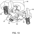
- the solenoid 60 is coupled to a carriage 62 that is axially movable along the solenoid 60.
- the carriage 62 is coupled to a set of carriage springs 64, the compression force of which distances the carriage 62 from the circuit board 58 in a rest position.
- the carriage 62 is configured to engage the set of movable contacts 48A, which presses down on the carriage 62 when in an unbiased resting position.
- the carriage 62 will oppose the resiliency of the abutting set of movable contacts 48A to advance the set movable contacts 48A in an upward direction and form electrical communication with the set of fixed contacts 48B.
- the upward movement of the set of movable contacts 48A stops once electrical communication is formed with the set of fixed contacts 48B.
- the resiliency of the abutting set of movable contacts 48A pushes the carriage 62 in a downward direction back to its original rest position, thereby effectively breaking the electrical connection between the set of movable contacts 48A and the set of fixed contacts 48B.
- the downward movement range of the set of movable contacts 48A is limited by a stopping plane in the solenoid support structure 61. Once the set of movable contacts 48A hits the stopping plane or returns to the unbiased resting position, push force is no longer exerted on the carriage 62, thereby effectively halting the downward movement and limiting the maximum range of movement of the carriage 62.
- Resetting and latching of the GFCI receptacle 10 may be controlled by the circuit board 58 that receives ground fault and arc fault signal inputs from the sense transformer cores 50, 51.
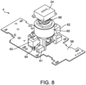
- FIG. 7 shows an exploded view of a solenoid assembly 4 of the GFCI receptacle 10 according to one embodiment of the present application.
- the solenoid assembly 4 includes a reset button 24, a reset spring 68, a solenoid 60, a reset plunger assembly 6, a solenoid support structure 61, and a circuit board 58.
- the solenoid support structure 61 is coupled to the circuit board 58 and supports the solenoid 60.
- the reset button 24 is biased away from the solenoid 60 via the reset spring 68 as long as no push force is exerted on the reset button 24.
- the compression force of the reset spring 68 returns the reset plunger 66 and the reset button 24 to an original resting position biased away from the solenoid support structure 61.
- the carriage 62 is biased away from the circuit board 58 via the set of carriage springs 64.
- the compression force of the carriage springs 64 returns the carriage 62 to an original position biased away from the circuit board 58 when external forces are removed.
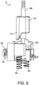
- the reset plunger assembly 6 includes a reset plunger 66 with an intermediate collar 78 and an armature 70 that is axially movable along the length of the reset plunger 66.
- the armature 70 contains a slanted projection feature 71 that is energized by the solenoid 60 through which the armature 70 extends.
- the slanted projection feature 71 is configured to engage with the latching mechanism, which is structurally supported by the carriage 62 and the set of carriage springs 64.
- the latching mechanism includes a cam surface 72 coupled to a lifting plate 74.
- the lifting plate 74 is coupled through a slot 75 in the carriage 62, as shown in FIG. 10 .
- the lifting plate 74 includes a latching portion 80 configured to receive and engage the intermediate collar 78 of the reset plunger 66 during resetting and tripping of the GFCI receptacle 10, as shown in FIG. 11 .
- a return spring 76 is coupled to one end of the lifting plate 74 and is configured to apply a compression force against one side of the carriage 62.
- FIGS. 12A-C Two exemplary embodiments of the latching mechanism are shown in FIGS. 12A-C .
- the cam surface 72A is configured as a separate triangular plate coupled to channels (not enumerated) in the lifting plate 74A.
- a set of tabs 73A at one end of the lifting plate 74A is configured to engage with edges of the cam surface 72A to transfer a translational force from the cam surface 72A to the lifting plate 74A.
- the return spring 76A is positioned between the other end of the lifting plate 74A and one side of the carriage 62A.
- the latching portion 80A is configured as the only opening in the lifting plate 74A and receives/engages with the intermediate collar 78.
- the cam surface 72B is integrated into the lifting plate 74B as one element. Since the cam surface 72B does not move independent of the lifting plate 74B, coupling mechanism including channels (not enumerated) and tabs 74A are not necessary in the lifting plate 74B.
- the lifting plate 74B includes an opening 77B and a latching portion 80B.
- the return spring 76B is situated in the opening 77B and exerts a compression force between edges of the opening 77B and one side of the carriage 62B.
- the latching portion 80B is configured to receive/engage with the intermediate collar 78. It would be appreciated by those skilled in the art that other design possibilities not detailed herein may serve to achieve essentially the same results and do not deviate from the teachings of the present application.
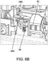
- a contact spring 82 is coupled to the bottom of the lifting plate 74.
- the contact spring 82 When in an unlatched pushing state as described in further detail below, the contact spring 82 will form electrical communication with at least one contact pads (not shown or enumerated) on the circuit board 58. This electrical communication will provide a communication signal and power from the circuit board 58 to the solenoid 60, thereby energizing the armature 70 and resetting the GFCI receptacle 10.
- the GFCI receptacle 10 has four different states: 1) unlatched state or tripped state, 2) unlatched pushing state, 3) latched pulling state, and 4) latched state or reset state.
- the carriage 62 is in a resting position biased away from the circuit board 58 via carriage springs 64, so the contact spring 82 (not shown) does not form electrical communication with at least one contact pads (not shown or enumerated) on the circuit board 58.
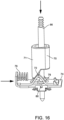
- the set of movable contacts 48A does not engage with the set of fixed contacts 48B (not shown), and the receptacle terminals 30, 32, 34 remain biased away from the receptacle openings 16, 18, 20 via cantilevered bus lines 44, 46. Therefore, the solenoid 60 does not receive external power and is not energized, causing the slanted projection feature 71 of the armature 70 to bias away from cam surface 72 ( FIG. 14B ). There is no compression force in the return spring 76, and the engaging portion 80 of the lifting plate 74 is not aligned to receive the intermediate collar 78 biased away from the lifting plate 74.
- the GFCI receptacle 10 enters the unlatched pushing state of FIG. 15 .
- the downward force pushes the reset plunger 66 towards the lifting plate 74 until the intermediate collar 78 engages with an upper surface of the engaging portion 80.
- the intermediate collar 78 engages with but does not latch to the upper surface of engaging portion 80.
- the downward force from the intermediate collar 78 transfers to the engaging portion 80 and the lifting plate 74, which results in downward movement of the carriage 62 via the slot 75 ( FIG. 10 ).
- the reset spring 68 When the user releases the downward pushing force on the reset plunger 66, the reset spring 68 provides an upward pulling force on the reset plunger 66 and intermediate collar 78, thereby latching and locking the intermediate collar 78 to a lower surface of the engaging portion 80. Hence, the GFCI receptacle 10 enters the latched pulling state of the resetting process.
- the axially upward movement of the carriage 62 opposes the resiliency of the abutting set of movable contacts 48A and disconnects the contact springs 82 (not shown) from the at least one contact pads (not shown or enumerated) on the circuit board 58, thus preventing continued energizations of the solenoid 60.
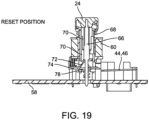
- the carriage 62 engages with the set of movable contacts 48A to form electrical connection with the set of fixed contacts 48B.
- the receptacle terminals 30, 32, 34 also resist the cantilevered bus lines 44, 46 and move closer to the front cover 12.
- the GFCI receptacle 10 completes a tripping process. During the tripping process, the GFCI receptacle 10 experiences the states of the resetting process in reverse order, thereby unlatching the intermediate collar 78 from the latching portion 80 and breaking the electrical communication between the set of movable contacts 48A and the set of fixed contacts 48B.
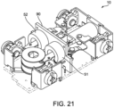
- FIGS. 20 & 21 illustrate a GFCI receptacle 10 according to some embodiments.
- the GFCI receptacle 10 includes a printed circuit board 90.
- the printed circuit board 90 includes one or more slots, or apertures, 92.
- the slots 92 may be configured receive, or be placed over, line conductors 94 and/or the neutral conductors 96, or a portion thereof (for example, bus bars 44, 46).
- the printed circuit board 90 may further include, or be coupled to, coils (for example, transformer cores 50, 51), which may be used to sense and/or monitor a current.
- the coils may also include a slot, aperture, configured to receive, or be placed over, the line conductors and/or the neutral conductors, or a portion thereof (for example, bus bars 44, 46).
- additional elements such as springs, contacts, etc., may be included in various places within the GFCI receptacle 10 to accomplish resetting or tripping of the device. All combinations of embodiments and variations of design are not exhaustively described in detail herein. Said combinations and variations are understood by those skilled in the art as not deviating from the teachings of the present application.
- An electrical outlet receptacle comprising: a housing including a face plate; a plurality of sensing cores each configured to receive a current flow through a center cavity, the current flow defining a current flow direction through the center cavity,wherein the current flow direction is parallel to the face plate, and wherein the plurality of sensing cores are place symmetrically in a translational direction across the electrical outlet receptacle.
- An electrical outlet receptacle comprising: a housing including a face plate; a sensing core configured to receive a current flow through a center cavity, the current flow defining a current flow direction through the center cavity, wherein the current flow direction is parallel to the face plate.
- the electrical outlet receptacle further comprising: a set of fixed contacts and a set of movable contacts; a solenoid having a central axis perpendicular to the face plate, a first end and a second end opposite the first end; a carriage movable axially along the solenoid and configured to interact with the set of movable contacts, the carriage configured to advance the set of movable contacts to form electrical communication with the set of fixed contacts during resetting of the electrical outlet receptacle; a reset plunger with a portion extending through the first end of the solenoid and axially movable therein, the reset plunger being biased toward a rest position away from the carriage; and an armature movable axially along the portion of the reset plunger extending through the solenoid, the armature being biased toward a rest position away from the carriage, wherein the reset plunger includes an engaging portion and the carriage includes a latching portion, the engaging portion of the reset plunger being configured to connect to the latching portion of the
- the electrical outlet receptacle wherein the solenoid includes a coil bobbin with an inner coil and an outer coil.
- the electrical outlet receptacle wherein the armature interacts with the latching portion of the carriage when the solenoid is momentarily energized to cause engagement of the engaging portion to the latching portion in a latched state.
- the electrical outlet receptacle wherein the armature interacts with the latching portion of the carriage when the solenoid is momentarily energized to cause engagement of the engaging portion to the latching portion in a latched state.
- the electrical outlet receptacle wherein in the latched state, the armature interacts with the latching portion of the carriage when the solenoid is momentarily energized to cause disengagement of the engaging portion from the latching portion in an unlatched state.
- the electrical outlet receptacle wherein pressing of the reset plunger causes the engaging portion to apply a downward force on the carriage at least until the electrical outlet receptacle is in the latched state, and subsequent release of the reset plunger causes the engaging portion to apply an upward force on the carriage to close the set of movable contacts and the set of fixed contacts.
- the at least one sensing core includes a ground fault circuit interrupter (GFCI) core and an arc fault circuit interrupter (AFCI) core, the GFCI core having a first current flow direction and the AFCI core having a second current flow direction.
- GFCI ground fault circuit interrupter
- AFCI arc fault circuit interrupter
- the electrical outlet receptacle wherein the first current flow direction and the second current flow direction are identical to each other.
- the electrical outlet receptacle wherein the first current flow direction and the second current flow direction are substantially parallel to each other.
- the electrical outlet receptacle wherein the first current flow direction and the second current flow direction are at an oblique angle to each other.
- the electrical outlet receptacle wherein the first current flow direction and the second current flow direction are at a right angle to each other.
- the electrical outlet receptacle wherein the GFCI core and AFCI core are positioned in a symmetrical placement across a translational direction of the electrical outlet receptacle, the symmetrical placement allowing for no interference of the GFCI core and the AFCI core with contact terminals connectable to an external device.
Landscapes
- Physics & Mathematics (AREA)
- General Physics & Mathematics (AREA)
- Engineering & Computer Science (AREA)
- Power Engineering (AREA)
- Details Of Connecting Devices For Male And Female Coupling (AREA)
- Breakers (AREA)
Applications Claiming Priority (3)
| Application Number | Priority Date | Filing Date | Title |
|---|---|---|---|
| US201762595760P | 2017-12-07 | 2017-12-07 | |
| PCT/US2018/064269 WO2019113329A1 (en) | 2017-12-07 | 2018-12-06 | Shallow electrical protection device (gfci, afci, and afci/gfci) system and method |
| EP18886862.4A EP3721511B1 (de) | 2017-12-07 | 2018-12-06 | Flache elektrische schutzvorrichtung (gfci, afci und afci/gfci), system und verfahren |
Related Parent Applications (1)
| Application Number | Title | Priority Date | Filing Date |
|---|---|---|---|
| EP18886862.4A Division EP3721511B1 (de) | 2017-12-07 | 2018-12-06 | Flache elektrische schutzvorrichtung (gfci, afci und afci/gfci), system und verfahren |
Publications (3)
| Publication Number | Publication Date |
|---|---|
| EP4407815A2 true EP4407815A2 (de) | 2024-07-31 |
| EP4407815A3 EP4407815A3 (de) | 2024-10-09 |
| EP4407815B1 EP4407815B1 (de) | 2025-10-15 |
Family
ID=66697393
Family Applications (2)
| Application Number | Title | Priority Date | Filing Date |
|---|---|---|---|
| EP24180288.3A Active EP4407815B1 (de) | 2017-12-07 | 2018-12-06 | System und verfahren für flache elektrische schutzvorrichtungen (gfci, afci und afci/gfci) |
| EP18886862.4A Active EP3721511B1 (de) | 2017-12-07 | 2018-12-06 | Flache elektrische schutzvorrichtung (gfci, afci und afci/gfci), system und verfahren |
Family Applications After (1)
| Application Number | Title | Priority Date | Filing Date |
|---|---|---|---|
| EP18886862.4A Active EP3721511B1 (de) | 2017-12-07 | 2018-12-06 | Flache elektrische schutzvorrichtung (gfci, afci und afci/gfci), system und verfahren |
Country Status (4)
| Country | Link |
|---|---|
| US (5) | US11309667B2 (de) |
| EP (2) | EP4407815B1 (de) |
| CN (2) | CN111492540B (de) |
| WO (1) | WO2019113329A1 (de) |
Cited By (1)
| Publication number | Priority date | Publication date | Assignee | Title |
|---|---|---|---|---|
| US10179104B2 (en) | 2011-09-29 | 2019-01-15 | Plx Opco Inc. | PH dependent carriers for targeted release of pharmaceuticals along the gastrointestinal tract, compositions therefrom, and making and using same |
Families Citing this family (8)
| Publication number | Priority date | Publication date | Assignee | Title |
|---|---|---|---|---|
| USD928713S1 (en) * | 2017-03-27 | 2021-08-24 | Wenzhou Mtlc Electric Appliances Co., Ltd. | Combination duplex electrical receptacle with USB charger and interchangeable face cover |
| USD935414S1 (en) * | 2017-03-27 | 2021-11-09 | Wenzhou Mtlc Electric Appliances Co., Ltd. | Combination electrical receptacle with USB charger and interchangeable face cover |
| USD931222S1 (en) * | 2017-03-27 | 2021-09-21 | Wenzhou Mtlc Electric Appliances Co., Ltd. | Combination duplex electrical receptacle with USB charger and interchangeable face cover |
| USD911972S1 (en) * | 2017-03-27 | 2021-03-02 | Wenzhou Mtlc Electric Appliances Co., Ltd. | Combination electrical receptacle with USB charger and interchangeable face cover |
| USD887983S1 (en) * | 2017-04-14 | 2020-06-23 | Lutron Technology Company Llc | Electrical receptacle |
| US10840654B2 (en) * | 2017-04-18 | 2020-11-17 | National Christmas Products Llc | Electrical plug for a safety grounded tree |
| US11309667B2 (en) * | 2017-12-07 | 2022-04-19 | Hubbell Incorporated | Shallow electrical protection device (GFCI, AFCI, and AFCI/GFCI) system and method |
| MX2024002889A (es) * | 2021-09-08 | 2024-03-22 | Hubbell Incorported | Interruptor de circuito de falla a tierra portatil y/o interruptor de circuito de falla de arco y metodo de operacion del mismo. |
Citations (1)
| Publication number | Priority date | Publication date | Assignee | Title |
|---|---|---|---|---|
| US8830015B2 (en) | 2012-03-16 | 2014-09-09 | Hubbell Incorporated | Compact latching mechanism for switched electrical device |
Family Cites Families (32)
| Publication number | Priority date | Publication date | Assignee | Title |
|---|---|---|---|---|
| CA1162576A (en) * | 1980-12-11 | 1984-02-21 | Wolfgang F. Bienwald | Resettable circuit breaker for use in ground fault circuit interrupters and the like |
| US4521824A (en) * | 1984-02-13 | 1985-06-04 | General Electric Company | Interrupter mechanism for a ground fault circuit interrupter |
| US4549241A (en) * | 1984-02-13 | 1985-10-22 | General Electric Company | Ground and test arrangement for a ground fault circuit interrupter |
| JP3246117B2 (ja) | 1993-09-16 | 2002-01-15 | 富士電機株式会社 | 漏電遮断器の1次導体 |
| US6282070B1 (en) * | 1998-08-24 | 2001-08-28 | Leviton Manufacturing Co., Inc. | Circuit interrupting system with independent trip and reset lockout |
| US6246558B1 (en) * | 1998-08-24 | 2001-06-12 | Leviton Manufacturing Company | Circuit interrupting device with reverse wiring protection |
| US9362077B2 (en) * | 2000-02-17 | 2016-06-07 | Pass & Seymour, Inc. | Electrical device with miswire protection and automated testing |
| US7598828B1 (en) * | 2004-07-28 | 2009-10-06 | Pass & Seymour, Inc. | Protection device with a sandwiched cantilever breaker mechanism |
| CN2439127Y (zh) | 2000-09-04 | 2001-07-11 | 黄华道 | 漏电保护插座 |
| CN1195311C (zh) * | 2002-08-01 | 2005-03-30 | 浙江东正电气有限公司 | 接地故障断路器的反接线保护装置 |
| CN1220236C (zh) * | 2002-10-09 | 2005-09-21 | 浙江东正电气有限公司 | 具有反接线保护功能的接地故障断路器 |
| CN100492793C (zh) * | 2003-02-03 | 2009-05-27 | 立维腾制造有限公司 | 利用机电复位件的断路装置和系统 |
| US7944331B2 (en) * | 2003-02-03 | 2011-05-17 | Leviton Manufacturing Co., Inc. | Circuit interrupting device with reverse wiring protection |
| US7049911B2 (en) | 2003-02-03 | 2006-05-23 | Leviton Manufacturing Co., Inc. | Circuit interrupting device and system utilizing electromechanical reset |
| US7855873B2 (en) * | 2004-09-13 | 2010-12-21 | Cooper Technologies Company | Panelboard for fusible switching disconnect devices |
| US7619861B2 (en) | 2004-09-29 | 2009-11-17 | Pass & Seymour, Inc. | Protective device having a thin construction |
| CN100370570C (zh) | 2005-02-05 | 2008-02-20 | 希珂尔电气有限公司 | 智能型具有反接线保护的接地故障断路器 |
| US7612973B2 (en) * | 2005-09-01 | 2009-11-03 | Leviton Manufacturing Co., Inc. | GFCI receptacle with single button for test-reset function |
| US7673114B2 (en) | 2006-01-19 | 2010-03-02 | International Business Machines Corporation | Dynamically improving memory affinity of logical partitions |
| US20070268635A1 (en) * | 2006-05-18 | 2007-11-22 | Gaetano Bonasia | Bi-directional ground fault circuit interrupter |
| US8093966B2 (en) * | 2008-07-31 | 2012-01-10 | Hubbell Incorporated | Impact solenoid assembly for an electrical receptacle |
| CN101752152A (zh) | 2008-12-15 | 2010-06-23 | 唐亚兵 | 具有多种保护功能的插座式漏电保护器 |
| US8861146B2 (en) | 2010-12-17 | 2014-10-14 | Pass & Seymour, Inc. | Electrical wiring device with protective features |
| US20120199062A1 (en) | 2011-02-08 | 2012-08-09 | GeoTree Technologies, Inc. | Method and Apparatus for Application of Mortar |
| US9774181B2 (en) * | 2012-03-16 | 2017-09-26 | Hubbell Incorporated | Enhanced auto-monitoring circuit and method for an electrical device |
| US8568152B1 (en) * | 2012-04-19 | 2013-10-29 | Pass & Seymour, Inc. | Shutter assembly for electrical devices |
| US9608433B2 (en) * | 2013-03-14 | 2017-03-28 | Hubbell Incorporated | GFCI test monitor circuit |
| EP2976529A4 (de) | 2013-03-18 | 2016-12-21 | Kavan Graybill | Solarantriebssteuerungssystem für ölpumpenzylinder |
| US10062535B2 (en) * | 2014-01-15 | 2018-08-28 | Hubbell Incorporated | Self-test GFCI device with dual solenoid coil electric control |
| US10072942B2 (en) * | 2016-05-03 | 2018-09-11 | Ivani, LLC | Electrical monitoring and network enabled electrical faceplate |
| WO2016085738A1 (en) | 2014-11-26 | 2016-06-02 | Hubbell Incorporated | Apparatuses and methods for passive fault monitoring of current sensing devices in protective circuit interrupters |
| US11309667B2 (en) * | 2017-12-07 | 2022-04-19 | Hubbell Incorporated | Shallow electrical protection device (GFCI, AFCI, and AFCI/GFCI) system and method |
-
2018
- 2018-12-06 US US16/212,141 patent/US11309667B2/en active Active
- 2018-12-06 CN CN201880081926.4A patent/CN111492540B/zh active Active
- 2018-12-06 CN CN202210812062.7A patent/CN115060942B/zh active Active
- 2018-12-06 EP EP24180288.3A patent/EP4407815B1/de active Active
- 2018-12-06 WO PCT/US2018/064269 patent/WO2019113329A1/en not_active Ceased
- 2018-12-06 EP EP18886862.4A patent/EP3721511B1/de active Active
-
2022
- 2022-03-18 US US17/698,690 patent/US11557862B2/en active Active
-
2023
- 2023-01-13 US US18/096,813 patent/US11862906B2/en active Active
- 2023-12-27 US US18/397,717 patent/US12413027B2/en active Active
-
2025
- 2025-09-09 US US19/323,440 patent/US20260011962A1/en active Pending
Patent Citations (1)
| Publication number | Priority date | Publication date | Assignee | Title |
|---|---|---|---|---|
| US8830015B2 (en) | 2012-03-16 | 2014-09-09 | Hubbell Incorporated | Compact latching mechanism for switched electrical device |
Cited By (1)
| Publication number | Priority date | Publication date | Assignee | Title |
|---|---|---|---|---|
| US10179104B2 (en) | 2011-09-29 | 2019-01-15 | Plx Opco Inc. | PH dependent carriers for targeted release of pharmaceuticals along the gastrointestinal tract, compositions therefrom, and making and using same |
Also Published As
| Publication number | Publication date |
|---|---|
| EP4407815B1 (de) | 2025-10-15 |
| US11862906B2 (en) | 2024-01-02 |
| US20260011962A1 (en) | 2026-01-08 |
| US20190181594A1 (en) | 2019-06-13 |
| EP4407815A3 (de) | 2024-10-09 |
| CN111492540A (zh) | 2020-08-04 |
| EP3721511B1 (de) | 2024-06-19 |
| EP3721511A1 (de) | 2020-10-14 |
| CN115060942A (zh) | 2022-09-16 |
| US20220209474A1 (en) | 2022-06-30 |
| US12413027B2 (en) | 2025-09-09 |
| US20240128693A1 (en) | 2024-04-18 |
| CN111492540B (zh) | 2022-08-02 |
| WO2019113329A1 (en) | 2019-06-13 |
| EP3721511A4 (de) | 2021-08-18 |
| US11309667B2 (en) | 2022-04-19 |
| US11557862B2 (en) | 2023-01-17 |
| US20230155329A1 (en) | 2023-05-18 |
| CN115060942B (zh) | 2025-09-05 |
Similar Documents
| Publication | Publication Date | Title |
|---|---|---|
| US12413027B2 (en) | Shallow electrical protection device (GFCI, AFCI, and AFCI/GFCI) system and method | |
| US11456138B2 (en) | Fault circuit interrupter device | |
| US7558034B2 (en) | Bi-directional ground fault circuit interrupter | |
| US7498909B2 (en) | Ground-fault circuit interrupter with reverse wiring protection | |
| CA2563190C (en) | Circuit interrupting device with a single test-reset button | |
| US20070268635A1 (en) | Bi-directional ground fault circuit interrupter | |
| US20090147416A1 (en) | Ground fault circuit interrupter | |
| EP2783435B1 (de) | Fassung | |
| CN108899259A (zh) | 漏电保护断路器 | |
| GB1581363A (en) | Circuit breaker assembly | |
| CN100533899C (zh) | 配备了插头阻挡装置的gfci插座 | |
| WO2015084768A1 (en) | Electrical switching apparatus including a remotely controllable actuator structured to move a push/pull operating handle |
Legal Events
| Date | Code | Title | Description |
|---|---|---|---|
| PUAI | Public reference made under article 153(3) epc to a published international application that has entered the european phase |
Free format text: ORIGINAL CODE: 0009012 |
|
| STAA | Information on the status of an ep patent application or granted ep patent |
Free format text: STATUS: THE APPLICATION HAS BEEN PUBLISHED |
|
| AC | Divisional application: reference to earlier application |
Ref document number: 3721511 Country of ref document: EP Kind code of ref document: P |
|
| AK | Designated contracting states |
Kind code of ref document: A2 Designated state(s): AL AT BE BG CH CY CZ DE DK EE ES FI FR GB GR HR HU IE IS IT LI LT LU LV MC MK MT NL NO PL PT RO RS SE SI SK SM TR |
|
| REG | Reference to a national code |
Ipc: H01R0013660000 Ref country code: DE Ref legal event code: R079 Ref document number: 602018086507 Country of ref document: DE Free format text: PREVIOUS MAIN CLASS: H01R0024760000 |
|
| PUAL | Search report despatched |
Free format text: ORIGINAL CODE: 0009013 |
|
| AK | Designated contracting states |
Kind code of ref document: A3 Designated state(s): AL AT BE BG CH CY CZ DE DK EE ES FI FR GB GR HR HU IE IS IT LI LT LU LV MC MK MT NL NO PL PT RO RS SE SI SK SM TR |
|
| RIC1 | Information provided on ipc code assigned before grant |
Ipc: H01R 24/76 20110101ALI20240905BHEP Ipc: H01R 13/66 20060101AFI20240905BHEP |
|
| STAA | Information on the status of an ep patent application or granted ep patent |
Free format text: STATUS: REQUEST FOR EXAMINATION WAS MADE |
|
| 17P | Request for examination filed |
Effective date: 20250206 |
|
| GRAP | Despatch of communication of intention to grant a patent |
Free format text: ORIGINAL CODE: EPIDOSNIGR1 |
|
| STAA | Information on the status of an ep patent application or granted ep patent |
Free format text: STATUS: GRANT OF PATENT IS INTENDED |
|
| RIC1 | Information provided on ipc code assigned before grant |
Ipc: H01R 24/76 20110101ALI20250513BHEP Ipc: H01R 13/66 20060101AFI20250513BHEP |
|
| INTG | Intention to grant announced |
Effective date: 20250522 |
|
| GRAS | Grant fee paid |
Free format text: ORIGINAL CODE: EPIDOSNIGR3 |
|
| GRAA | (expected) grant |
Free format text: ORIGINAL CODE: 0009210 |
|
| STAA | Information on the status of an ep patent application or granted ep patent |
Free format text: STATUS: THE PATENT HAS BEEN GRANTED |
|
| AC | Divisional application: reference to earlier application |
Ref document number: 3721511 Country of ref document: EP Kind code of ref document: P |
|
| AK | Designated contracting states |
Kind code of ref document: B1 Designated state(s): AL AT BE BG CH CY CZ DE DK EE ES FI FR GB GR HR HU IE IS IT LI LT LU LV MC MK MT NL NO PL PT RO RS SE SI SK SM TR |
|
| P01 | Opt-out of the competence of the unified patent court (upc) registered |
Free format text: CASE NUMBER: UPC_APP_6561_4407815/2025 Effective date: 20250910 |
|
| REG | Reference to a national code |
Ref country code: GB Ref legal event code: FG4D Ref country code: CH Ref legal event code: F10 Free format text: ST27 STATUS EVENT CODE: U-0-0-F10-F00 (AS PROVIDED BY THE NATIONAL OFFICE) Effective date: 20251015 |
|
| PGFP | Annual fee paid to national office [announced via postgrant information from national office to epo] |
Ref country code: FR Payment date: 20250925 Year of fee payment: 8 |
|
| REG | Reference to a national code |
Ref country code: DE Ref legal event code: R096 Ref document number: 602018086507 Country of ref document: DE |
|
| REG | Reference to a national code |
Ref country code: IE Ref legal event code: FG4D |
|
| PGFP | Annual fee paid to national office [announced via postgrant information from national office to epo] |
Ref country code: GB Payment date: 20251017 Year of fee payment: 8 |
|
| REG | Reference to a national code |
Ref country code: NL Ref legal event code: MP Effective date: 20251015 |
|
| REG | Reference to a national code |
Ref country code: AT Ref legal event code: MK05 Ref document number: 1847895 Country of ref document: AT Kind code of ref document: T Effective date: 20251015 |
|
| PG25 | Lapsed in a contracting state [announced via postgrant information from national office to epo] |
Ref country code: NL Free format text: LAPSE BECAUSE OF FAILURE TO SUBMIT A TRANSLATION OF THE DESCRIPTION OR TO PAY THE FEE WITHIN THE PRESCRIBED TIME-LIMIT Effective date: 20251015 |
|
| PG25 | Lapsed in a contracting state [announced via postgrant information from national office to epo] |
Ref country code: ES Free format text: LAPSE BECAUSE OF FAILURE TO SUBMIT A TRANSLATION OF THE DESCRIPTION OR TO PAY THE FEE WITHIN THE PRESCRIBED TIME-LIMIT Effective date: 20251015 |
|
| REG | Reference to a national code |
Ref country code: LT Ref legal event code: MG9D |
|
| PG25 | Lapsed in a contracting state [announced via postgrant information from national office to epo] |
Ref country code: NO Free format text: LAPSE BECAUSE OF FAILURE TO SUBMIT A TRANSLATION OF THE DESCRIPTION OR TO PAY THE FEE WITHIN THE PRESCRIBED TIME-LIMIT Effective date: 20260115 |
|
| PGFP | Annual fee paid to national office [announced via postgrant information from national office to epo] |
Ref country code: DE Payment date: 20251217 Year of fee payment: 8 |
|
| PG25 | Lapsed in a contracting state [announced via postgrant information from national office to epo] |
Ref country code: FI Free format text: LAPSE BECAUSE OF FAILURE TO SUBMIT A TRANSLATION OF THE DESCRIPTION OR TO PAY THE FEE WITHIN THE PRESCRIBED TIME-LIMIT Effective date: 20251015 Ref country code: HR Free format text: LAPSE BECAUSE OF FAILURE TO SUBMIT A TRANSLATION OF THE DESCRIPTION OR TO PAY THE FEE WITHIN THE PRESCRIBED TIME-LIMIT Effective date: 20251015 Ref country code: AT Free format text: LAPSE BECAUSE OF FAILURE TO SUBMIT A TRANSLATION OF THE DESCRIPTION OR TO PAY THE FEE WITHIN THE PRESCRIBED TIME-LIMIT Effective date: 20251015 |
|
| PG25 | Lapsed in a contracting state [announced via postgrant information from national office to epo] |
Ref country code: RS Free format text: LAPSE BECAUSE OF FAILURE TO SUBMIT A TRANSLATION OF THE DESCRIPTION OR TO PAY THE FEE WITHIN THE PRESCRIBED TIME-LIMIT Effective date: 20260115 |
|
| PG25 | Lapsed in a contracting state [announced via postgrant information from national office to epo] |
Ref country code: IS Free format text: LAPSE BECAUSE OF FAILURE TO SUBMIT A TRANSLATION OF THE DESCRIPTION OR TO PAY THE FEE WITHIN THE PRESCRIBED TIME-LIMIT Effective date: 20260215 |
|
| PG25 | Lapsed in a contracting state [announced via postgrant information from national office to epo] |
Ref country code: PT Free format text: LAPSE BECAUSE OF FAILURE TO SUBMIT A TRANSLATION OF THE DESCRIPTION OR TO PAY THE FEE WITHIN THE PRESCRIBED TIME-LIMIT Effective date: 20260216 |
|
| PG25 | Lapsed in a contracting state [announced via postgrant information from national office to epo] |
Ref country code: PL Free format text: LAPSE BECAUSE OF FAILURE TO SUBMIT A TRANSLATION OF THE DESCRIPTION OR TO PAY THE FEE WITHIN THE PRESCRIBED TIME-LIMIT Effective date: 20251015 |
|
| PG25 | Lapsed in a contracting state [announced via postgrant information from national office to epo] |
Ref country code: LV Free format text: LAPSE BECAUSE OF FAILURE TO SUBMIT A TRANSLATION OF THE DESCRIPTION OR TO PAY THE FEE WITHIN THE PRESCRIBED TIME-LIMIT Effective date: 20251015 |