EP4407813A1 - Connector holder for an electrical connection assembly for a wiring harness of a vehicle - Google Patents
Connector holder for an electrical connection assembly for a wiring harness of a vehicle Download PDFInfo
- Publication number
- EP4407813A1 EP4407813A1 EP23153537.8A EP23153537A EP4407813A1 EP 4407813 A1 EP4407813 A1 EP 4407813A1 EP 23153537 A EP23153537 A EP 23153537A EP 4407813 A1 EP4407813 A1 EP 4407813A1
- Authority
- EP
- European Patent Office
- Prior art keywords
- connector
- electrical
- assembly
- connector holder
- electrical connection
- Prior art date
- Legal status (The legal status is an assumption and is not a legal conclusion. Google has not performed a legal analysis and makes no representation as to the accuracy of the status listed.)
- Pending
Links
Images


Classifications
-
- B—PERFORMING OPERATIONS; TRANSPORTING
- B60—VEHICLES IN GENERAL
- B60R—VEHICLES, VEHICLE FITTINGS, OR VEHICLE PARTS, NOT OTHERWISE PROVIDED FOR
- B60R16/00—Electric or fluid circuits specially adapted for vehicles and not otherwise provided for; Arrangement of elements of electric or fluid circuits specially adapted for vehicles and not otherwise provided for
- B60R16/02—Electric or fluid circuits specially adapted for vehicles and not otherwise provided for; Arrangement of elements of electric or fluid circuits specially adapted for vehicles and not otherwise provided for electric constitutive elements
- B60R16/0207—Wire harnesses
- B60R16/0215—Protecting, fastening and routing means therefor
-
- H—ELECTRICITY
- H01—ELECTRIC ELEMENTS
- H01R—ELECTRICALLY-CONDUCTIVE CONNECTIONS; STRUCTURAL ASSOCIATIONS OF A PLURALITY OF MUTUALLY-INSULATED ELECTRICAL CONNECTING ELEMENTS; COUPLING DEVICES; CURRENT COLLECTORS
- H01R13/00—Details of coupling devices of the kinds covered by groups H01R12/70 or H01R24/00 - H01R33/00
- H01R13/62—Means for facilitating engagement or disengagement of coupling parts or for holding them in engagement
- H01R13/639—Additional means for holding or locking coupling parts together, after engagement, e.g. separate keylock, retainer strap
-
- B—PERFORMING OPERATIONS; TRANSPORTING
- B60—VEHICLES IN GENERAL
- B60R—VEHICLES, VEHICLE FITTINGS, OR VEHICLE PARTS, NOT OTHERWISE PROVIDED FOR
- B60R16/00—Electric or fluid circuits specially adapted for vehicles and not otherwise provided for; Arrangement of elements of electric or fluid circuits specially adapted for vehicles and not otherwise provided for
- B60R16/02—Electric or fluid circuits specially adapted for vehicles and not otherwise provided for; Arrangement of elements of electric or fluid circuits specially adapted for vehicles and not otherwise provided for electric constitutive elements
- B60R16/023—Electric or fluid circuits specially adapted for vehicles and not otherwise provided for; Arrangement of elements of electric or fluid circuits specially adapted for vehicles and not otherwise provided for electric constitutive elements for transmission of signals between vehicle parts or subsystems
- B60R16/0238—Electrical distribution centers
-
- H—ELECTRICITY
- H01—ELECTRIC ELEMENTS
- H01B—CABLES; CONDUCTORS; INSULATORS; SELECTION OF MATERIALS FOR THEIR CONDUCTIVE, INSULATING OR DIELECTRIC PROPERTIES
- H01B7/00—Insulated conductors or cables characterised by their form
- H01B7/0045—Cable-harnesses
-
- H—ELECTRICITY
- H01—ELECTRIC ELEMENTS
- H01B—CABLES; CONDUCTORS; INSULATORS; SELECTION OF MATERIALS FOR THEIR CONDUCTIVE, INSULATING OR DIELECTRIC PROPERTIES
- H01B7/00—Insulated conductors or cables characterised by their form
- H01B7/40—Insulated conductors or cables characterised by their form with arrangements for facilitating mounting or securing
-
- H—ELECTRICITY
- H01—ELECTRIC ELEMENTS
- H01R—ELECTRICALLY-CONDUCTIVE CONNECTIONS; STRUCTURAL ASSOCIATIONS OF A PLURALITY OF MUTUALLY-INSULATED ELECTRICAL CONNECTING ELEMENTS; COUPLING DEVICES; CURRENT COLLECTORS
- H01R13/00—Details of coupling devices of the kinds covered by groups H01R12/70 or H01R24/00 - H01R33/00
- H01R13/62—Means for facilitating engagement or disengagement of coupling parts or for holding them in engagement
- H01R13/629—Additional means for facilitating engagement or disengagement of coupling parts, e.g. aligning or guiding means, levers, gas pressure electrical locking indicators, manufacturing tolerances
- H01R13/631—Additional means for facilitating engagement or disengagement of coupling parts, e.g. aligning or guiding means, levers, gas pressure electrical locking indicators, manufacturing tolerances for engagement only
- H01R13/6315—Additional means for facilitating engagement or disengagement of coupling parts, e.g. aligning or guiding means, levers, gas pressure electrical locking indicators, manufacturing tolerances for engagement only allowing relative movement between coupling parts, e.g. floating connection
-
- H—ELECTRICITY
- H01—ELECTRIC ELEMENTS
- H01R—ELECTRICALLY-CONDUCTIVE CONNECTIONS; STRUCTURAL ASSOCIATIONS OF A PLURALITY OF MUTUALLY-INSULATED ELECTRICAL CONNECTING ELEMENTS; COUPLING DEVICES; CURRENT COLLECTORS
- H01R13/00—Details of coupling devices of the kinds covered by groups H01R12/70 or H01R24/00 - H01R33/00
- H01R13/73—Means for mounting coupling parts to apparatus or structures, e.g. to a wall
- H01R13/74—Means for mounting coupling parts in openings of a panel
- H01R13/741—Means for mounting coupling parts in openings of a panel using snap fastening means
- H01R13/745—Means for mounting coupling parts in openings of a panel using snap fastening means separate from the housing
-
- H—ELECTRICITY
- H01—ELECTRIC ELEMENTS
- H01R—ELECTRICALLY-CONDUCTIVE CONNECTIONS; STRUCTURAL ASSOCIATIONS OF A PLURALITY OF MUTUALLY-INSULATED ELECTRICAL CONNECTING ELEMENTS; COUPLING DEVICES; CURRENT COLLECTORS
- H01R24/00—Two-part coupling devices, or either of their cooperating parts, characterised by their overall structure
-
- H—ELECTRICITY
- H01—ELECTRIC ELEMENTS
- H01R—ELECTRICALLY-CONDUCTIVE CONNECTIONS; STRUCTURAL ASSOCIATIONS OF A PLURALITY OF MUTUALLY-INSULATED ELECTRICAL CONNECTING ELEMENTS; COUPLING DEVICES; CURRENT COLLECTORS
- H01R2201/00—Connectors or connections adapted for particular applications
- H01R2201/26—Connectors or connections adapted for particular applications for vehicles
Definitions
- the present disclosure relates to a connector holder for an electrical connection assembly for a wiring harness of a vehicle, the electrical connection assembly and the vehicle.
- Harness assembly in plant and connection of electrical connectors is a large fraction of the total assembly time of vehicles and is almost exclusively performed by manual labor.
- electrical connectors often lead to ergonomic issues from high assembly forces and/or assembly in positions that are difficult to reach or lead to inefficient designs to allow for manual assembly.
- wiring harnesses have mostly been designed to circumvent the above issues, e.g., by adding overlength on the harness to allow for manual assembly outside of the intended position with increased cost and assembly time.
- the problem is to provide an electrical connection assembly that at least partially solves at least one of the above problems.
- a connector holder for an electrical connection assembly for a wiring harness of a vehicle comprising:
- the connector holder having the attachment portions and the spring portions is flexible in the movement plane by allowing elastic deformation of the spring portions. Allowing it to move when forces are being exerted onto the first electrical connector mounted or, in other words, mechanically connected thereto. This allows for greater tolerance ranges because it reduces the risk that the respectively connected electrical connectors or a thereto attached wiring harness and/or electrical component breaks. This advantage may, for example, further be used to use shorter wiring harnesses and to ergonomically improve the assembly process.
- Tolerances are an issue for autodocked connector assembly.
- a position tolerance of a mechanical part (after e.g. manual assembly) can be in an order of ⁇ 1 mm
- a connector for autodocking requires a position tolerance in an order of ⁇ 0.1 mm.
- the connector holder according to the invention may ensure that the connector can be assembled in the correct position even if there is a difference of position tolerances and therefore probably a misalignment between the mechanical part and the connector as it allows for the connector to float. So it may be an enabler for autodocking or automated assembly of connectors.
- connection assembly of this disclosure is primarily suggested to be used for a wiring harness of a vehicle, other components inside of the vehicle may be connected via the electrical connection assembly as well, as will be explained in more detail by the example of an electrical component.
- the electrical connection assembly is not limited to be used in a vehicle, but it can also be used in other applications or devices benefitting from a higher tolerance and ergonomic advantages when electrically connecting wires, electrical components, and so on with one another.
- the electrical connectors may be respectively designed as male and female or socket and plug type connectors such that they can be mated with each other. Any mating or locking mechanism may be used. For example, to simplify disassembly, it is possible to use friction locked electrical connectors. Alternatively, electrical connectors with locking latch may be used.
- the electrical connectors may be stand-alone electrical connectors or attached to further components.
- the electrical connectors or at least one of them may be an electrical component having the respective electrical connector.
- the first electrical connector may be part (integral or removably attached) of an electric component.
- the connector holder may either hold an electrical connector itself or a more complex part having the electrical connector, such as an electrical component. Accordingly, the flexible properties of the connector holder may be used to move an entire electrical component, if desired.
- the connector holder comprises several portions, namely a main portion, at least two attachment portions and at least two spring portions. These portions are connected to each other. They may be designed monolithically or, in other words, integrally with each other. Also, the herein mentioned mount interface may be designed monolithically with the connector holder. This has the advantage of a very robust connector holder that can absorb high forces in order to ease any tension on the connectors themselves.
- the spring characteristic of the spring portions may be configured by choice of material, shape and dimensions, e.g., thickness, of the spring portions.
- Material-wise, the connector holder may be made from any material, in particular elastic material, including metals and/or synthetic materials. Regarding the shape, possible examples will be given further below.
- the movement plane is a plane spanned by two axes.
- the movement of the main portion and thereby the first electrical connector, which is attached to the main portion, is being enabled in the movement plane. This does not limit the main portion to perform movements along the assembly axis if necessary and at least to a certain degree such that tolerances can be made up along the assembly axis as well.
- the movement plane being oblique to the assembly axis in other words means that the assembly axis is inclined with respect to the movement plane.
- the oblique orientation or, in other words, inclination may be substantially perpendicular or, in other words, at an angle of substantially 90°, as will be explained later in more detail.
- the main portion may comprise a mount interface for receiving a first electrical connector of the electrical connection assembly along the assembly axis and mounting the first electrical connector to the main portion.
- the main portion is configured for attaching the first electrical connector of the electrical connection assembly thereto, particularly along the assembly axis.
- the first electrical connector may be mechanically attached to the main portion of the connector holder.
- the assembly axis may be a coinciding axis for the attachment of the first electrical connector to the main portion and for the attachment of the second electrical connector to the first electrical connector. Accordingly, a particularly easy assembly may be provided by matching assembling directions for different assemblies.
- the first electrical connector can be a separate component mountable to the main portion by means of the mount interface.
- the mount interface may, for example, be configured with preloaded claws or hooks, between which the first electrical connector can be positioned and locked by means of the preload.
- the mount interface may be omitted and/or the main portion may have the first electrical connector attached thereto, particularly permanently attached thereto.
- Such attachment may be established by means of the assembly as described or, alternatively, when the mount interface is omitted, by means of an integral design of the main portion and the first electrical connector or parts of it, for example.
- the first electrical connector can be at least partially, particularly with its connector housing, designed integrally with the main portion.
- the assembly axis may be at least partially determined or defined by the attachment of the first electrical connector to the main portion.
- the orientation of the first electrical connector defined by its attachment to the main portion may define along which axis or direction the second electrical connector can be mated with the first electrical connector.
- Another part in the definition or determination of the assembly axis for connecting the respective electrical connectors with each other may of course be the design of the connector(s) themselves.
- the integral design has the advantage that less assembly steps are necessary to assemble the electrical connection assembly.
- the connector holder may be more difficult and expensive to manufacture with the first electrical connector being permanently attached thereto.
- the main portion may have an interface aperture enabling access for electrical connection to the first electrical connector when the first electrical connector is attached to the main portion.
- This interface aperture may be located underneath the mount interface, if present. The interface aperture thereby makes it ergonomically easy to electrically connect the wiring harness, for example, to the first electrical connector.
- the movement plane may be substantially perpendicular to the assembly axis.
- the two axes spanning the movement plane are substantially perpendicular to the assembly axis.
- Substantially perpendicular includes deviations of a perpendicular orientation of up to 10 degrees in either direction.
- the spring portions may be configured as curved links between the main portion and the attachment portions.
- the curvature of these links is a simple and cost-effective way to provide the spring characteristics that are needed to compensate for tolerances along the entire electrical connection of a wiring harness.
- the curved links may have an S- or meander-formed curvature.
- the curvature refers to the extension in length of the links or spring portions in the movement plane, meaning the axes spanning the movement plane.
- An S-formed curvature is a particularly simple curvature enabling simple yet effective movement of the main portion and thereby the first electrical connector in many different directions. Adding more curves, the S-formed curvature may be transitioned in design to a meander-formed curvature. Such curvature further increases the flexibility of the connector holder.
- the curved links may have a band or tape shaped profile.
- the band or tape width particularly extends perpendicular to the movement plane or along the assembly axis.
- the band or tape shape of the profile of the curved links thereby allows for mostly unrestricted movement of the curved links in the movement plane, while limiting the movement range along the assembly axis.
- the attachment portions may be designed as pins.
- the pins may be extending in length along the assembly axis or substantially perpendicular to the movement plane. Such pins may be inserted into corresponding pin apertures, in particular pin holes, of the base assembly part for attaching the connector holder to the base assembly part.
- the base assembly part can be fixed to a structure or frame of the vehicle. The pins enable a simple and quick assembly and disassembly with the base assembly part, in particular when they also extend in length along the assembly axis.
- the pins may be designed as rotation pins, the rotation pins being able to rotate within pin apertures of the base assembly part.
- the pin apertures or pin holes can be designed (slightly) larger in diameter than the rotation pins.
- the pins may have circumferentially provided supporting rings for supporting the connector holder on the base assembly part when the pins are inserted into pin apertures of the base assembly part.
- the diameters of the support rings may be greater than diameters of the pin apertures for this purpose. This means that they may be sized such that the support rings support the connector holder on the base assembly part when the pins are inserted into the pin apertures.
- the support rings may be provided at a distance measured along the assembly axis from the main portion and/or the spring portions. In other words, the support rings may be positioned below a lower edge of the main portion and/or the spring portions. Thereby, the main portion and the spring portions may be lifted or raised atop of the base assembly part.
- the main portion and the spring portions are not obstructed by the base assembly part or the attachment thereto. Accordingly, unobstructed movement of the connector holder in the movement plane is enabled. Also, a certain movement of the connector holder along the assembly axis is enabled. The movement range along the assembly axis is determined by the distance of the support rings to the lower edge of the main portion and spring portions.
- the connector holder may comprise at least four attachment portions and at least four spring portions. While it is possible to have less attachment portions and spring portions, such as three of each, for example, having at least four proved to be advantageous to have a large movement range of the main portion of the connector holder and thereby the first electrical connector.
- an electrical connection assembly for a wiring harness of a vehicle comprising:
- the electrical connection assembly may have further parts as described in this disclosure.
- the electrical connection assembly may further comprise the base assembly part and/or the second electrical connector.
- the electrical connection assembly may include any number of wires, cables, wiring harnesses and electrical components, which may be electrically connected to each other via the two electrical connectors.
- the respective parts of the electrical connection assembly may be available assembled, i.e., mechanically and/or electrically connected to each other, or unassembled.
- the connector holder may be mechanically attached to the base assembly part by means of the previously mentioned pins being inserted into the pin apertures, or these parts may be provided in an unassembled state. Of importance is merely whether the corresponding parts for assembly of the electrical connection assembly are provided.
- the electrical connection assembly may comprise a further connector holder, the further connector holder comprising a receptacle connector interface for receiving the second electrical connector along the assembly axis and mounting the second electrical connector to the further connector holder.
- the further connector holder may have the second electrical connector permanently attached thereto, e.g., by means of integral design.
- the further connector holder may have at least two further attachment portions, in particular at least four further attachment portions, for attaching the further connector holder to the base assembly part.
- the further attachment portions may be designed as attachment domes, for example.
- the base assembly part may comprise corresponding attachment means such as attachment apertures for inserting and fixing the attachment domes therein, particularly by means of a form fit.
- the receptacle connector interface and/or the second electrical connector may have a funnel shape for guiding the first electrical connector for electrical connection to the second electrical connector mounted to the further connector holder.
- the funnel shape enables autodocking or, in other words, blind mating of the two electrical connectors with each other. This further eases and accelerates the assembly of the electrical connection assembly.
- the funnel shape may be provided in the receptable connector interface itself or on a connector housing of the second electrical connector, for example.
- the funnel shape may be widening in the direction, particularly along the assembly axis, towards the first electrical connector or, in other words, away from the second electrical connector, such that the funnel gets narrower when the first electrical connector is guided along it and ultimately mates with the second electrical connector.
- the electrical connection assembly may further comprise an electrical component, the electrical component comprising the second electrical connector and a printed-circuit board connected to the second electrical connector. While it is possible to use the electrical connection assembly for connecting wiring harnesses or portions thereof with each other, it is also possible to directly connect an electrical component, such as a vehicle control unit, for example, with the wiring harness.
- the wiring harness may be wired to the first electrical connector and the electrical component may have the second electrical connector mating with the first electrical connector.
- the second electrical connector of the electrical component it is possible that the second electrical connector has exposed electrical connection pins because a type of housing protecting these from being damaged may be formed by the further connector holder, forming a type of a cover of the electrical component.
- a vehicle having the electrical connection assembly according to the second aspect of this disclosure, the wiring harness of the vehicle being electrically connected to the first electrical connector and/or the second electrical connector.
- the respective other electrical connector may be connected to the same or another wiring harness or an electrical component, for example.
- the attachment of the electrical connection assembly inside the vehicle may be performed by means of the base assembly part.
- Such base assembly part may be attached to a structure or frame inside the vehicle.
- the base assembly part may comprise attachment recesses, through which the base assembly part may be bolted to the vehicle structure or frame. Adhesion or form fit are alternative exemplary options of attachment to structures of the vehicle.
- the above examples may be combined with each other irrespective of the aspect involved. Accordingly, the connector holder may be combined with the electrical connection assembly and vice versa.
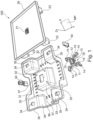
- Figure 1 shows an exploded view of an example of an electrical connection assembly 100 for a wiring harness 210 (see Fig. 3 and 9 ) of a vehicle 200 (see Fig. 9 ).
- Fig. 7 shows an assembled state of the electrical connection assembly 100.
- the electrical connection assembly 100 comprises a connector holder 10 having several portions, namely a main portion 11, attachment portions 14 and spring portions 15. A top view of the connector holder 10 is shown in Fig. 2 .
- the connector holder 10 comprises four attachment portions 14 and four spring portions 15. A different number of attachment portions 14 and spring portions 15 is possible.
- Each one of the spring portions 15 is attached to the main portion 11 located in the center of the connector holder 10. Each one of the four spring portions 15 extends away from the main portion 11 in a different direction and from a different point of the main portion 11. Each one of the attachment portions 14 is located at a respective end of the spring portion 15. In this example, each one of the spring portions 15 is configured as a curved link connecting the main portion 11 with one of the attachment portions 14.
- each of the spring portions 15 extends away from a different corner of a substantially rectangular shape of the main portion 11.
- each one of the spring portions 15 or curved links has an S-formed or S-shaped curvature between the point of connection to the main portion 11 and its respective attachment portion 14.
- the shape of the spring portions 15 may have more curves and generally be meander-formed, which includes any number of curves along the length or longitudinal trajectory of a spring portion 15.
- all spring portions 15 are formed alike.
- the main portion 11 corresponds in shape to the rectangular shape of the first electrical connector 40.
- the main portion 11 of this example has a mount interface 12, which may be designed integral with the main portion 11 or be attached thereto as a separate part.
- the mount interface 12 is designed such that the first electrical connector 40 can be mechanically attached to the connector holder 10.
- the main portion 11 has an interface aperture 13, which enables access for an electrical part such as one or multiple electrical wires to the first electrical connector 40 when the first electrical connector 40 is mounted to the main portion 11 via the mount interface 12.
- different shapes such as circular, oval, octagonal etc. can be used for either one of these or both.
- the connector holder 10 extends in a plane that is spanned by the axes X and Y as shown in Fig. 1 and 2 .
- This plane is also being referred to as a movement plane MP.
- the spring portions 15 extend in the movement plane MP with their length.
- the S- or meander-shape extends in the movement plane MP.
- the spring portions 15 extend along the shown Z axis perpendicular to the axes X and Y and thus perpendicular to the movement plane MP.
- the spring portions 15 have a band or tape shaped profile along the Z axis, as may be taken from Fig. 3
- the attachment portions 14 at the ends of the spring portions 15 are designed as pins. These pins extend in length along the Z axis.
- the pins have support rings 17.
- the support rings 17 have a greater diameter than the pins themselves.
- the support rings 17 are positioned between the ends of the pins and the main portion 11 and/or the spring portions 15. Particularly, the support rings 17 are positioned slightly below a lower edge of the main portion 11 and/or the spring portions 15, which allows for a slim design.
- the connector holder 10 On a base assembly part 30 of the electrical connection assembly 10. Fixing the connector holder 10 to the base assembly part 30 may be performed by inserting the pins into corresponding pin apertures 32 of the base assembly part 30, which is performed along the Z axis, which is also referred to herein as the assembly axis.
- the pin apertures 32 correspond in location and size to the arrangement and size of the pins. Due to the support rings 17, the main portion 11 and the spring portions 15 are being supported on top of the base assembly part 30, more particularly a center portion 33 of the base assembly part 30 that is elevated from a base surface 36 of the base assembly part 30, while being able to move freely in the movement plane MP.
- the center portion 33 comprises a connection aperture 31 corresponding in location to the location of the interface aperture 13. This further allows for accessing the first electrical connector 40 from under the interface aperture 13.
- the main portion also comprises a widened interface aperture 16 underneath the interface aperture 13 at the top side of the main portion seen in Fig. 2 . This allows for easier access to the first electrical connector 40.
- the pins are designed as rotation pins that are being able to rotate within the pin apertures 32.
- the pin apertures 32 are designed to be slightly larger in diameter than the pins. This allows the pins to rotate inside the pin apertures 32.
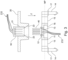
- the assembly of the entire electrical connection assembly 100 can be performed along the assembly axis Z and more particularly along one direction of the assembly axis Z as indicated by the arrow in Fig. 3 .
- the first electrical connector 40 can be mounted onto the connector holder 10 via the indicated direction along assembly axis Z in Fig. 3
- the connector holder 10 can be attached via its pins to the base assembly part 30 in that same direction
- the second electrical connector 50 can be mated with the first electrical connector 40 in that same direction
- the further connector holder 20 can be attached to the base assembly part 30 in that same direction, as will be explained later.
- the assembly axis Z for the other parts of the electrical connection assembly 100 may remain.
- the assembly axis Z may be defined by the mating of the first electrical connector 40 with the second electrical connector 50.
- the second electrical connector 50 may be subjected to a force and transfer that force acting along the X and/or Y axis to the first electrical connector 40.
- the first electrical connector 40 will absorb that force acting in the movement plane MP by means of the spring characteristics of the spring portions 15 of the connector holder 40 and further by means of rotation of the pins inside the pin apertures 32.
- a flexible electrical connection assembly 100 is provided, which, by means of the spring portions 15 and the pins and corresponding pin apertures 32, can react to forces along the chain of electrical connections between two electrical connectors 40, 50. This prevents the electrical connectors 40, 50 from breaking and enables flexibility in designing the wiring harness 210 inside a vehicle 200.
- the electrical connection assembly 100 may comprise a further connector holder 20 as shown in Fig. 1 . While the connector holder 10 is designed to hold the first electrical connector 40, the further connector holder 20 is designed to hold the second electrical connector 50.
- One of the two electrical connectors 40, 50 may be of a plug type, while the respective other one may be of a socket type. In the example of Fig. 1 , the first electrical connector 40 is designed as a plug and the second electrical connector 50 is designed as a socket.
- the further connector holder 20 for the second electrical connector 50 comprises a receptacle connector interface 21 for mounting the second electrical connector 50. This feature can be seen best in the assembly operation shown in Fig. 3 . There, the second electrical connector 50 is inserted into the receptacle connector interface 21 of the further connector holder 20. The further connector holder 20 and the connector holder 10, with the respective electrical connectors 40, 50 mounted, are assembled along the Z axis.
- the receptacle connector interface 21 has a funnel shape 22.
- the funnel shape 22 widens in the direction away from the second electrical connector 50 and towards the first electrical connector 40. This allows for blindly guiding the first electrical connector 40 to the second electrical connector 50 and thereby blind mating the connectors 40, 50.
- the base assembly part 30 and the further connector holder 20 have exemplary rectangular shapes, which substantially correspond in size of their outer dimensions to each other. However, alternative shapes may be used.
- the base assembly part 30 comprises four further attachment portions 23 designed as mounting domes extending along the Z axis. Alternatively, the number of further attachment portions 23 may be different and they may be designed in any other suitable way, such as pins. These further attachment portions 23 are located at the edges of the rectangular shaped further connector holder 20. While the connector holder 10 is flexible by means of its spring portions 15, the further connector holder 20 has no such flexibility and is substantially stiff. This allows for aligning or attaching the further connector holder 20 to the base assembly part 30.
- the base assembly part 30 has attachment apertures 34 located and sized corresponding to the further attachment portions 23 of the further connector holder 20 such that the further attachment portions 23 may be inserted into the attachment apertures 34 thereby attaching the further connector holder 20 to the base assembly part 30.
- the attachment apertures 34 are located on respective edge portions 35 that are elevated from the base surface 36 of the base assembly part 30.
- the base surface 36 is provided with attachment recesses 37. Via the attachment recesses 37, the base assembly part 30 can be conveniently attached to the vehicle 200. Of course, other means of attachment, such as adhesion or form fit may be used in the alternative.
- both electrical connectors 40, 50 are connected to a wiring harness 210 inside the vehicle 200 as depicted exemplary in Fig. 9 .
- the wiring harness 210 is schematically illustrated by means of multiple wires in Fig. 3 .
- one or both electrical connectors 40, 50 may be connected to or be part of an electrical component 60 such as the one shown in Figs. 4 to 6 .
- Figs. 4 to 6 show different examples of alternatives to the upper part of the electrical connection assembly 100 in Fig. 3 , namely the second electrical connector 50 and/or the further connector holder 20.
- an electrical component 60 is formed by the second electrical connector 50 and a printed circuit board 61.
- the second electrical connector 50 is exemplary formed by means of multiple electrical connection pins 51.
- the second electrical connector 50 in this example does not have a connector housing, while the second electrical connector 50 in the example of Fig. 5 has a connector housing 52 surrounding the electrical connection pins 51.
- the electrical component 60 may be any vehicle electrical component, such as a vehicle control unit, for example.
- the funnel shape 22 for guiding the first electrical connector 40 to the second electrical connector 50 is provided on the connector housing 52 of the second electrical connector 50 rather than the receptacle connector interface 21 of the further connector holder 20.
- Fig. 7 depicts the electrical connection assembly 100 as explained with reference to Figs. 1 to 3 in the assembled state.
- the further connector holder 20 is illustrated as a transparent part.
- the connector holder 10 can react to that force by corresponding movement in the movement plane MP, effectively preventing any damage to the connection between the electrical connectors 40, 50 and possibly to the wiring harness 210 and/or electrical components 60 attached thereto.
- the funnel shape 22 due to the funnel shape 22, a fast and easy mating of the electrical connectors 40, 50 is possible.
- the entire assembly may be performed along a single direction of the assembly axis Z.
- Fig. 8 shows a cross section of the electrical connection assembly 100 for a detail where the electric connectors 40, 50 are electrically connected to each other.
- the first electrical connector 40 is mechanically fixed via the mount interface 12 to the connector holder 10.
- the further connector holder 20 has the second electrical connector 50 mounted thereto. From underneath the first electrical connector 40, via the interface aperture 13 and the connection aperture 31, access is given for electrically connecting the wiring harness 210 to the first electrical connector 40.
- Fig. 9 schematically depicts an example of a vehicle 200, in which the described assembled electrical connection assembly 100 is used in the connection of a wiring harness 210. Additionally, or alternatively, the electrical connection assembly 100 may be used to connect to one or more electrical component 60, such as previously described, or to connect a wiring harness 210 to such electrical component 60.
Landscapes
- Engineering & Computer Science (AREA)
- Mechanical Engineering (AREA)
- Details Of Connecting Devices For Male And Female Coupling (AREA)
Abstract
The disclosure relates to a connector holder (10) for an electrical connection assembly (100) for a wiring harness (210) of a vehicle (200), the electrical connection assembly (100) and a vehicle (200) having the electrical connection assembly (100). The connector holder (10) comprising a main portion (11) for attaching a first electrical connector (40) of the electrical connection assembly (100) thereto or having the first electrical connector (40) attached thereto, a second electrical connector (50) being connectable to the first electrical connector (40) along an assembly axis (Z), the assembly axis (Z) extending along the attachment of the first electrical connector (40) to the main portion (11). The connector holder (10) comprising at least two attachment portions (14) for attaching the connector holder (10) to a base assembly part (30) of the electrical connection assembly (100), and at least two spring portions (15), each of the spring portions (15) being connected to a respective one of the attachment portions (14) and having a spring characteristic to allow movement of the main portion (11) in a movement plane (MP) oblique to the assembly axis (Z) when the connector holder (10) is attached to the base assembly part (30) by means of the attachment portions (14).
Description
- The present disclosure relates to a connector holder for an electrical connection assembly for a wiring harness of a vehicle, the electrical connection assembly and the vehicle.
- Electrification and demand for more customer functionality leads to a growing number of electrical connectors in vehicles. The wiring harness reaches all parts of the vehicle. Harness assembly in plant and connection of electrical connectors is a large fraction of the total assembly time of vehicles and is almost exclusively performed by manual labor. In addition, electrical connectors often lead to ergonomic issues from high assembly forces and/or assembly in positions that are difficult to reach or lead to inefficient designs to allow for manual assembly.
- Also, meeting the required tolerances is often a problem for the assembly. If the tolerances are not met, electrical failures in the vehicle may occur. Detecting such errors may be very time-consuming and therefore cost-intensive.
- In the automotive industry, wiring harnesses have mostly been designed to circumvent the above issues, e.g., by adding overlength on the harness to allow for manual assembly outside of the intended position with increased cost and assembly time.
- No assembly concept is known which solves the ergonomic issues without technical drawbacks having economic disadvantages, such as overlength or tolerance problems.
- The problem is to provide an electrical connection assembly that at least partially solves at least one of the above problems.
- The problem is at least partially solved or alleviated by the subject matter of the independent claims of the present disclosure, wherein further examples are incorporated in the dependent claims.
- According to a first aspect, there is provided a connector holder for an electrical connection assembly for a wiring harness of a vehicle, the connector holder comprising:
- a main portion for attaching a first electrical connector of the electrical connection assembly thereto or having the first electrical connector attached thereto, the first electrical connector in particular being configured as a plug or a socket, a second electrical connector being connectable to the first electrical connector along an assembly axis, the assembly axis extending along the attachment of the first electrical connector to the main portion or being at least partially determined by the attachment of the first electrical connector to the main portion,
- at least two attachment portions for attaching the connector holder to a base assembly part of the electrical connection assembly, and
- at least two spring portions, each of the spring portions being connected to a respective one of the attachment portions and having a spring characteristic to allow movement of the main portion in a movement plane oblique to the assembly axis when the connector holder is attached to the base assembly part by means of the attachment portions.
- The connector holder having the attachment portions and the spring portions is flexible in the movement plane by allowing elastic deformation of the spring portions. Allowing it to move when forces are being exerted onto the first electrical connector mounted or, in other words, mechanically connected thereto. This allows for greater tolerance ranges because it reduces the risk that the respectively connected electrical connectors or a thereto attached wiring harness and/or electrical component breaks. This advantage may, for example, further be used to use shorter wiring harnesses and to ergonomically improve the assembly process.
- Tolerances are an issue for autodocked connector assembly. In a vehicle installation, a position tolerance of a mechanical part (after e.g. manual assembly) can be in an order of ~1 mm, while a connector for autodocking requires a position tolerance in an order of ~0.1 mm. The connector holder according to the invention may ensure that the connector can be assembled in the correct position even if there is a difference of position tolerances and therefore probably a misalignment between the mechanical part and the connector as it allows for the connector to float. So it may be an enabler for autodocking or automated assembly of connectors.
- While the electrical connection assembly of this disclosure is primarily suggested to be used for a wiring harness of a vehicle, other components inside of the vehicle may be connected via the electrical connection assembly as well, as will be explained in more detail by the example of an electrical component. Also, the electrical connection assembly is not limited to be used in a vehicle, but it can also be used in other applications or devices benefitting from a higher tolerance and ergonomic advantages when electrically connecting wires, electrical components, and so on with one another.
- The electrical connectors may be respectively designed as male and female or socket and plug type connectors such that they can be mated with each other. Any mating or locking mechanism may be used. For example, to simplify disassembly, it is possible to use friction locked electrical connectors. Alternatively, electrical connectors with locking latch may be used.
- Moreover, the electrical connectors may be stand-alone electrical connectors or attached to further components. Particularly, the electrical connectors or at least one of them may be an electrical component having the respective electrical connector. For example, the first electrical connector may be part (integral or removably attached) of an electric component. Accordingly, the connector holder may either hold an electrical connector itself or a more complex part having the electrical connector, such as an electrical component. Accordingly, the flexible properties of the connector holder may be used to move an entire electrical component, if desired.
- The connector holder comprises several portions, namely a main portion, at least two attachment portions and at least two spring portions. These portions are connected to each other. They may be designed monolithically or, in other words, integrally with each other. Also, the herein mentioned mount interface may be designed monolithically with the connector holder. This has the advantage of a very robust connector holder that can absorb high forces in order to ease any tension on the connectors themselves.
- The spring characteristic of the spring portions may be configured by choice of material, shape and dimensions, e.g., thickness, of the spring portions. Material-wise, the connector holder may be made from any material, in particular elastic material, including metals and/or synthetic materials. Regarding the shape, possible examples will be given further below.
- The movement plane is a plane spanned by two axes. The movement of the main portion and thereby the first electrical connector, which is attached to the main portion, is being enabled in the movement plane. This does not limit the main portion to perform movements along the assembly axis if necessary and at least to a certain degree such that tolerances can be made up along the assembly axis as well. The movement plane being oblique to the assembly axis in other words means that the assembly axis is inclined with respect to the movement plane. The oblique orientation or, in other words, inclination may be substantially perpendicular or, in other words, at an angle of substantially 90°, as will be explained later in more detail.
- The main portion may comprise a mount interface for receiving a first electrical connector of the electrical connection assembly along the assembly axis and mounting the first electrical connector to the main portion. In other words, it is possible that the main portion is configured for attaching the first electrical connector of the electrical connection assembly thereto, particularly along the assembly axis. In this case, by means of assembly along the assembly axis, the first electrical connector may be mechanically attached to the main portion of the connector holder. In this case, the assembly axis may be a coinciding axis for the attachment of the first electrical connector to the main portion and for the attachment of the second electrical connector to the first electrical connector. Accordingly, a particularly easy assembly may be provided by matching assembling directions for different assemblies. The first electrical connector can be a separate component mountable to the main portion by means of the mount interface. The mount interface may, for example, be configured with preloaded claws or hooks, between which the first electrical connector can be positioned and locked by means of the preload.
- Alternatively, the mount interface may be omitted and/or the main portion may have the first electrical connector attached thereto, particularly permanently attached thereto. Such attachment may be established by means of the assembly as described or, alternatively, when the mount interface is omitted, by means of an integral design of the main portion and the first electrical connector or parts of it, for example. In such case, the first electrical connector can be at least partially, particularly with its connector housing, designed integrally with the main portion. Particularly in such case, the assembly axis may be at least partially determined or defined by the attachment of the first electrical connector to the main portion. For example, the orientation of the first electrical connector defined by its attachment to the main portion may define along which axis or direction the second electrical connector can be mated with the first electrical connector. Another part in the definition or determination of the assembly axis for connecting the respective electrical connectors with each other may of course be the design of the connector(s) themselves. The integral design has the advantage that less assembly steps are necessary to assemble the electrical connection assembly. However, the connector holder may be more difficult and expensive to manufacture with the first electrical connector being permanently attached thereto.
- The main portion may have an interface aperture enabling access for electrical connection to the first electrical connector when the first electrical connector is attached to the main portion. This interface aperture may be located underneath the mount interface, if present. The interface aperture thereby makes it ergonomically easy to electrically connect the wiring harness, for example, to the first electrical connector.
- The movement plane may be substantially perpendicular to the assembly axis. Thereby, the two axes spanning the movement plane are substantially perpendicular to the assembly axis. Substantially perpendicular includes deviations of a perpendicular orientation of up to 10 degrees in either direction. By having a substantially perpendicular orientation, a tolerance compensation in either of the two axes of the movement plane or the assembly axis may be optimally performed by the connector holder.
- The spring portions may be configured as curved links between the main portion and the attachment portions. The curvature of these links is a simple and cost-effective way to provide the spring characteristics that are needed to compensate for tolerances along the entire electrical connection of a wiring harness.
- The curved links may have an S- or meander-formed curvature. The curvature refers to the extension in length of the links or spring portions in the movement plane, meaning the axes spanning the movement plane. An S-formed curvature is a particularly simple curvature enabling simple yet effective movement of the main portion and thereby the first electrical connector in many different directions. Adding more curves, the S-formed curvature may be transitioned in design to a meander-formed curvature. Such curvature further increases the flexibility of the connector holder.
- The curved links may have a band or tape shaped profile. The band or tape width particularly extends perpendicular to the movement plane or along the assembly axis. The band or tape shape of the profile of the curved links thereby allows for mostly unrestricted movement of the curved links in the movement plane, while limiting the movement range along the assembly axis.
- The attachment portions may be designed as pins. The pins may be extending in length along the assembly axis or substantially perpendicular to the movement plane. Such pins may be inserted into corresponding pin apertures, in particular pin holes, of the base assembly part for attaching the connector holder to the base assembly part. The base assembly part can be fixed to a structure or frame of the vehicle. The pins enable a simple and quick assembly and disassembly with the base assembly part, in particular when they also extend in length along the assembly axis.
- The pins may be designed as rotation pins, the rotation pins being able to rotate within pin apertures of the base assembly part. The pin apertures or pin holes can be designed (slightly) larger in diameter than the rotation pins. Thereby, a rotation of the pins is enabled, which in turn enables greater elastic deformation of the spring portions for more movement of the first electrical connector in any direction of the movement plane. Accordingly, greater tolerances can be compensated for.
- The pins may have circumferentially provided supporting rings for supporting the connector holder on the base assembly part when the pins are inserted into pin apertures of the base assembly part. The diameters of the support rings may be greater than diameters of the pin apertures for this purpose. This means that they may be sized such that the support rings support the connector holder on the base assembly part when the pins are inserted into the pin apertures. More particularly, the support rings may be provided at a distance measured along the assembly axis from the main portion and/or the spring portions. In other words, the support rings may be positioned below a lower edge of the main portion and/or the spring portions. Thereby, the main portion and the spring portions may be lifted or raised atop of the base assembly part. Accordingly, when the main portion is moved when the spring portions are subjected to a force elastically deforming them, the main portion and the spring portions are not obstructed by the base assembly part or the attachment thereto. Accordingly, unobstructed movement of the connector holder in the movement plane is enabled. Also, a certain movement of the connector holder along the assembly axis is enabled. The movement range along the assembly axis is determined by the distance of the support rings to the lower edge of the main portion and spring portions.
- The connector holder may comprise at least four attachment portions and at least four spring portions. While it is possible to have less attachment portions and spring portions, such as three of each, for example, having at least four proved to be advantageous to have a large movement range of the main portion of the connector holder and thereby the first electrical connector.
- According to a second aspect, there is provided an electrical connection assembly for a wiring harness of a vehicle, the electrical connection assembly comprising:
- the connector holder according to the first aspect of this disclosure, and
- the first electrical connector for electrically connecting to a second electrical connector of the electrical connection assembly, the first electrical connector being attached to the connector holder, the second electrical connector in particular being configured as a plug or a socket such that it corresponds for electrically connecting to the first electrical connector.
- Besides having the connector holder and the first electrical connector, the electrical connection assembly may have further parts as described in this disclosure. For example, the electrical connection assembly may further comprise the base assembly part and/or the second electrical connector. Also, the electrical connection assembly may include any number of wires, cables, wiring harnesses and electrical components, which may be electrically connected to each other via the two electrical connectors.
- The respective parts of the electrical connection assembly may be available assembled, i.e., mechanically and/or electrically connected to each other, or unassembled. For example, the connector holder may be mechanically attached to the base assembly part by means of the previously mentioned pins being inserted into the pin apertures, or these parts may be provided in an unassembled state. Of importance is merely whether the corresponding parts for assembly of the electrical connection assembly are provided.
- The electrical connection assembly may comprise a further connector holder, the further connector holder comprising a receptacle connector interface for receiving the second electrical connector along the assembly axis and mounting the second electrical connector to the further connector holder. Using the further connector holder, it is possible to improve the ergonomics for the assembly further. In the alternative, the further connector holder may have the second electrical connector permanently attached thereto, e.g., by means of integral design.
- Particularly, the further connector holder may have at least two further attachment portions, in particular at least four further attachment portions, for attaching the further connector holder to the base assembly part. The further attachment portions may be designed as attachment domes, for example. The base assembly part may comprise corresponding attachment means such as attachment apertures for inserting and fixing the attachment domes therein, particularly by means of a form fit.
- The receptacle connector interface and/or the second electrical connector may have a funnel shape for guiding the first electrical connector for electrical connection to the second electrical connector mounted to the further connector holder. The funnel shape enables autodocking or, in other words, blind mating of the two electrical connectors with each other. This further eases and accelerates the assembly of the electrical connection assembly. The funnel shape may be provided in the receptable connector interface itself or on a connector housing of the second electrical connector, for example. The funnel shape may be widening in the direction, particularly along the assembly axis, towards the first electrical connector or, in other words, away from the second electrical connector, such that the funnel gets narrower when the first electrical connector is guided along it and ultimately mates with the second electrical connector.
- The electrical connection assembly may further comprise an electrical component, the electrical component comprising the second electrical connector and a printed-circuit board connected to the second electrical connector. While it is possible to use the electrical connection assembly for connecting wiring harnesses or portions thereof with each other, it is also possible to directly connect an electrical component, such as a vehicle control unit, for example, with the wiring harness. In this case, the wiring harness may be wired to the first electrical connector and the electrical component may have the second electrical connector mating with the first electrical connector. For the second electrical connector of the electrical component, it is possible that the second electrical connector has exposed electrical connection pins because a type of housing protecting these from being damaged may be formed by the further connector holder, forming a type of a cover of the electrical component. In the alternative, it is possible to provide a separate connector housing for the second electrical connector, adding a further layer of security but also material, weight and cost.
- According to a third aspect, there is provided a vehicle having the electrical connection assembly according to the second aspect of this disclosure, the wiring harness of the vehicle being electrically connected to the first electrical connector and/or the second electrical connector.
- As previously explained, the respective other electrical connector may be connected to the same or another wiring harness or an electrical component, for example.
- The attachment of the electrical connection assembly inside the vehicle may be performed by means of the base assembly part. Such base assembly part may be attached to a structure or frame inside the vehicle. For example, the base assembly part may comprise attachment recesses, through which the base assembly part may be bolted to the vehicle structure or frame. Adhesion or form fit are alternative exemplary options of attachment to structures of the vehicle.
- It should be noted that the above examples may be combined with each other irrespective of the aspect involved. Accordingly, the connector holder may be combined with the electrical connection assembly and vice versa.
- These and other aspects of the present disclosure will become apparent from and elucidated with reference to the examples described hereinafter.
- Examples of the disclosure will be described in the following with reference to the following drawings:
- Fig. 1
- shows an exploded view of an example of an electrical connection assembly for a wiring harness of a vehicle in an unassembled state,
- Fig. 2
- shows a top view of a connector holder of the electrical connection assembly of
Fig. 1 , - Fig. 3
- shows a cross-sectional view of the electrical connection assembly of
Fig. 1 while carrying out assembly of the electrical connection assembly, - Fig. 4
- shows a cross-sectional view of a first example of an electrical component in part of the electrical connection assembly of
Fig. 3 , - Fig. 5
- shows a cross-sectional view of a second example of the electrical component according to
Fig. 4 , - Fig. 6
- shows a cross-sectional view of a third example of the electrical component according to
Fig. 4 , - Fig. 7
- shows a perspective view of the electrical connection assembly of
Fig. 1 in an assembled state, - Fig. 8
- shows a cross-sectional view of a detail of the assembled electrical connection assembly, and
- Fig. 9
- shows a perspective transparent view of an example of a vehicle comprising the electrical connection assembly of
Fig. 1 . - The figures are merely schematic representations and serve only to illustrate examples of the disclosure. Identical or equivalent elements are in principle provided with the same reference signs.
-
Figure 1 shows an exploded view of an example of anelectrical connection assembly 100 for a wiring harness 210 (seeFig. 3 and9 ) of a vehicle 200 (seeFig. 9 ). Here, different parts of theelectrical connection assembly 100, as they will be explained with more detail in the following, are not assembled.Fig. 7 shows an assembled state of theelectrical connection assembly 100. - The
electrical connection assembly 100 comprises aconnector holder 10 having several portions, namely amain portion 11,attachment portions 14 andspring portions 15. A top view of theconnector holder 10 is shown inFig. 2 . In this example of theconnector holder 10, theconnector holder 10 comprises fourattachment portions 14 and fourspring portions 15. A different number ofattachment portions 14 andspring portions 15 is possible. - Each one of the
spring portions 15 is attached to themain portion 11 located in the center of theconnector holder 10. Each one of the fourspring portions 15 extends away from themain portion 11 in a different direction and from a different point of themain portion 11. Each one of theattachment portions 14 is located at a respective end of thespring portion 15. In this example, each one of thespring portions 15 is configured as a curved link connecting themain portion 11 with one of theattachment portions 14. - More particularly, each of the
spring portions 15 extends away from a different corner of a substantially rectangular shape of themain portion 11. In this example, each one of thespring portions 15 or curved links has an S-formed or S-shaped curvature between the point of connection to themain portion 11 and itsrespective attachment portion 14. However, the shape of thespring portions 15 may have more curves and generally be meander-formed, which includes any number of curves along the length or longitudinal trajectory of aspring portion 15. In this example, allspring portions 15 are formed alike. However, it is possible to have different forms or sizes of thespring portions 15 in order to affect the overall spring characteristic of theconnector holder 10 in different directions. - In this example, the
main portion 11 corresponds in shape to the rectangular shape of the firstelectrical connector 40. Themain portion 11 of this example has amount interface 12, which may be designed integral with themain portion 11 or be attached thereto as a separate part. Themount interface 12 is designed such that the firstelectrical connector 40 can be mechanically attached to theconnector holder 10. In addition, themain portion 11 has aninterface aperture 13, which enables access for an electrical part such as one or multiple electrical wires to the firstelectrical connector 40 when the firstelectrical connector 40 is mounted to themain portion 11 via themount interface 12. Despite themain portion 11 and the firstelectrical connector 40 being shown with rectangular shape, different shapes, such as circular, oval, octagonal etc. can be used for either one of these or both. - Generally, the
connector holder 10 extends in a plane that is spanned by the axes X and Y as shown inFig. 1 and2 . This plane is also being referred to as a movement plane MP. Thespring portions 15 extend in the movement plane MP with their length. The S- or meander-shape extends in the movement plane MP. In width, thespring portions 15 extend along the shown Z axis perpendicular to the axes X and Y and thus perpendicular to the movement plane MP. Particularly, thespring portions 15 have a band or tape shaped profile along the Z axis, as may be taken fromFig. 3 - The
attachment portions 14 at the ends of thespring portions 15 are designed as pins. These pins extend in length along the Z axis. The pins have support rings 17. The support rings 17 have a greater diameter than the pins themselves. The support rings 17 are positioned between the ends of the pins and themain portion 11 and/or thespring portions 15. Particularly, the support rings 17 are positioned slightly below a lower edge of themain portion 11 and/or thespring portions 15, which allows for a slim design. - It is possible to place the
connector holder 10 on abase assembly part 30 of theelectrical connection assembly 10. Fixing theconnector holder 10 to thebase assembly part 30 may be performed by inserting the pins into correspondingpin apertures 32 of thebase assembly part 30, which is performed along the Z axis, which is also referred to herein as the assembly axis. For this purpose, thepin apertures 32 correspond in location and size to the arrangement and size of the pins. Due to the support rings 17, themain portion 11 and thespring portions 15 are being supported on top of thebase assembly part 30, more particularly acenter portion 33 of thebase assembly part 30 that is elevated from abase surface 36 of thebase assembly part 30, while being able to move freely in the movement plane MP. This is because thespring portions 15 and themain portion 11 do not contact thebase assembly part 30. Instead, the pins with their support rings 17 raise theconnector holder 10 to a height above thebase assembly part 30. Moreover, thecenter portion 33 comprises aconnection aperture 31 corresponding in location to the location of theinterface aperture 13. This further allows for accessing the firstelectrical connector 40 from under theinterface aperture 13. As can further be seen fromFig. 3 , the main portion also comprises a widenedinterface aperture 16 underneath theinterface aperture 13 at the top side of the main portion seen inFig. 2 . This allows for easier access to the firstelectrical connector 40. - The pins are designed as rotation pins that are being able to rotate within the
pin apertures 32. For this purpose, thepin apertures 32 are designed to be slightly larger in diameter than the pins. This allows the pins to rotate inside thepin apertures 32. - As can be seen from
Fig. 1 andFig. 3 , the assembly of the entireelectrical connection assembly 100 can be performed along the assembly axis Z and more particularly along one direction of the assembly axis Z as indicated by the arrow inFig. 3 . The firstelectrical connector 40 can be mounted onto theconnector holder 10 via the indicated direction along assembly axis Z inFig. 3 , theconnector holder 10 can be attached via its pins to thebase assembly part 30 in that same direction, the secondelectrical connector 50 can be mated with the firstelectrical connector 40 in that same direction and, finally, thefurther connector holder 20 can be attached to thebase assembly part 30 in that same direction, as will be explained later. - Instead of assembling the first
electrical connector 40 and theconnector holder 10 with each other it may be provided that they are designed integrally with one another. However, the assembly axis Z for the other parts of theelectrical connection assembly 100 may remain. In particular, the assembly axis Z may be defined by the mating of the firstelectrical connector 40 with the secondelectrical connector 50. - Coming back to the example of the Figures, when the first
electrical connector 40 is mounted to theconnector holder 10, and the firstelectrical connector 40 is further connected to the secondelectrical connector 50, the secondelectrical connector 50 may be subjected to a force and transfer that force acting along the X and/or Y axis to the firstelectrical connector 40. The firstelectrical connector 40 will absorb that force acting in the movement plane MP by means of the spring characteristics of thespring portions 15 of theconnector holder 40 and further by means of rotation of the pins inside thepin apertures 32. Accordingly, a flexibleelectrical connection assembly 100 is provided, which, by means of thespring portions 15 and the pins andcorresponding pin apertures 32, can react to forces along the chain of electrical connections between twoelectrical connectors electrical connectors wiring harness 210 inside avehicle 200. - Besides the two
electrical connectors connector holder 10 and thebase assembly part 30, theelectrical connection assembly 100 may comprise afurther connector holder 20 as shown inFig. 1 . While theconnector holder 10 is designed to hold the firstelectrical connector 40, thefurther connector holder 20 is designed to hold the secondelectrical connector 50. One of the twoelectrical connectors Fig. 1 , the firstelectrical connector 40 is designed as a plug and the secondelectrical connector 50 is designed as a socket. - The
further connector holder 20 for the secondelectrical connector 50 comprises areceptacle connector interface 21 for mounting the secondelectrical connector 50. This feature can be seen best in the assembly operation shown inFig. 3 . There, the secondelectrical connector 50 is inserted into thereceptacle connector interface 21 of thefurther connector holder 20. Thefurther connector holder 20 and theconnector holder 10, with the respectiveelectrical connectors - As can be seen best in
Fig. 3 , thereceptacle connector interface 21 has afunnel shape 22. Thefunnel shape 22 widens in the direction away from the secondelectrical connector 50 and towards the firstelectrical connector 40. This allows for blindly guiding the firstelectrical connector 40 to the secondelectrical connector 50 and thereby blind mating theconnectors - The
base assembly part 30 and thefurther connector holder 20 have exemplary rectangular shapes, which substantially correspond in size of their outer dimensions to each other. However, alternative shapes may be used. Thebase assembly part 30 comprises fourfurther attachment portions 23 designed as mounting domes extending along the Z axis. Alternatively, the number offurther attachment portions 23 may be different and they may be designed in any other suitable way, such as pins. Thesefurther attachment portions 23 are located at the edges of the rectangular shapedfurther connector holder 20. While theconnector holder 10 is flexible by means of itsspring portions 15, thefurther connector holder 20 has no such flexibility and is substantially stiff. This allows for aligning or attaching thefurther connector holder 20 to thebase assembly part 30. For this reason, thebase assembly part 30 hasattachment apertures 34 located and sized corresponding to thefurther attachment portions 23 of thefurther connector holder 20 such that thefurther attachment portions 23 may be inserted into theattachment apertures 34 thereby attaching thefurther connector holder 20 to thebase assembly part 30. In this example, theattachment apertures 34 are located onrespective edge portions 35 that are elevated from thebase surface 36 of thebase assembly part 30. - To secure the
base assembly part 30 inside avehicle 200, particularly to some vehicle frame or structure, along which awire harness 210 may be provided, thebase surface 36 is provided with attachment recesses 37. Via the attachment recesses 37, thebase assembly part 30 can be conveniently attached to thevehicle 200. Of course, other means of attachment, such as adhesion or form fit may be used in the alternative. - As shown in
Fig. 3 , bothelectrical connectors wiring harness 210 inside thevehicle 200 as depicted exemplary inFig. 9 . Thewiring harness 210 is schematically illustrated by means of multiple wires inFig. 3 . Alternatively, one or bothelectrical connectors electrical component 60 such as the one shown inFigs. 4 to 6 . -
Figs. 4 to 6 show different examples of alternatives to the upper part of theelectrical connection assembly 100 inFig. 3 , namely the secondelectrical connector 50 and/or thefurther connector holder 20. - In
Fig. 4 , anelectrical component 60 is formed by the secondelectrical connector 50 and a printedcircuit board 61. The secondelectrical connector 50 is exemplary formed by means of multiple electrical connection pins 51. The secondelectrical connector 50 in this example does not have a connector housing, while the secondelectrical connector 50 in the example ofFig. 5 has aconnector housing 52 surrounding the electrical connection pins 51. Theelectrical component 60 may be any vehicle electrical component, such as a vehicle control unit, for example. - In the example of
Fig. 6 , thefunnel shape 22 for guiding the firstelectrical connector 40 to the secondelectrical connector 50 is provided on theconnector housing 52 of the secondelectrical connector 50 rather than thereceptacle connector interface 21 of thefurther connector holder 20. -
Fig. 7 depicts theelectrical connection assembly 100 as explained with reference toFigs. 1 to 3 in the assembled state. Thefurther connector holder 20 is illustrated as a transparent part. In the assembled state of theelectrical connection assembly 100, when thefurther connector holder 20 and/or the secondelectrical connector 50 are subjected to a force, theconnector holder 10 can react to that force by corresponding movement in the movement plane MP, effectively preventing any damage to the connection between theelectrical connectors wiring harness 210 and/orelectrical components 60 attached thereto. Moreover, due to thefunnel shape 22, a fast and easy mating of theelectrical connectors -
Fig. 8 shows a cross section of theelectrical connection assembly 100 for a detail where theelectric connectors electrical connector 40 is mechanically fixed via themount interface 12 to theconnector holder 10. Thefurther connector holder 20 has the secondelectrical connector 50 mounted thereto. From underneath the firstelectrical connector 40, via theinterface aperture 13 and theconnection aperture 31, access is given for electrically connecting thewiring harness 210 to the firstelectrical connector 40. -
Fig. 9 schematically depicts an example of avehicle 200, in which the described assembledelectrical connection assembly 100 is used in the connection of awiring harness 210. Additionally, or alternatively, theelectrical connection assembly 100 may be used to connect to one or moreelectrical component 60, such as previously described, or to connect awiring harness 210 to suchelectrical component 60. - Other variations to the disclosed examples can be understood and effected by those skilled in the art in practicing the claimed disclosure, from the study of the drawings, the disclosure, and the appended claims. In the claims the word "comprising" or "having" does not exclude other elements or steps and the indefinite article "a" or "an" does not exclude a plurality. The mere fact that certain measures are recited in mutually different dependent claims does not indicate that a combination of these measures cannot be used to advantage. Any reference signs in the claims should not be construed as limiting the scope of the claims.
-
- 10
- connector holder
- 11
- main portion
- 12
- mount interface
- 13
- interface aperture
- 14
- attachment portion
- 15
- spring portion
- 16
- widened interface aperture
- 17
- support rings
- 20
- further connector holder
- 21
- receptacle connector interface
- 22
- funnel shape
- 23
- further attachment portion
- 30
- base assembly part
- 31
- connection aperture
- 32
- pin aperture
- 33
- center portion
- 34
- attachement aperture
- 35
- edge portion
- 36
- base surface
- 37
- attachment recess
- 40
- first electrical connector
- 50
- second electrical connector
- 51
- electrical connection pin
- 52
- connector housing
- 60
- electrical component
- 61
- printed circuit board
- 100
- electrical connection assembly
- 200
- vehicle
- 210
- wiring harness
Claims (15)
- A connector holder (10) for an electrical connection assembly (100) for a wiring harness (210) of a vehicle (200), the connector holder (10) comprising:- a main portion (11) for attaching a first electrical connector (40) of the electrical connection assembly (100) thereto or having the first electrical connector (40) attached thereto, a second electrical connector (50) being connectable to the first electrical connector (40) along an assembly axis (Z), the assembly axis (Z) extending along the attachment of the first electrical connector (40) to the main portion (11),- at least two attachment portions (14) for attaching the connector holder (10) to a base assembly part (30) of the electrical connection assembly (100), and- at least two spring portions (15), each of the spring portions (15) being connected to a respective one of the attachment portions (14) and having a spring characteristic to allow movement of the main portion (11) in a movement plane (MP) oblique to the assembly axis (Z) when the connector holder (10) is attached to the base assembly part (30) by means of the attachment portions (14).
- The connector holder (10) according to claim 1, the main portion (11) comprising a mount interface (12) for receiving a first electrical connector (40) of the electrical connection assembly (100) along the assembly axis (Z) and mounting the first electrical connector (40) to the main portion (11).
- The connector holder (10) according to claim 1 or 2, the main portion (11) having an interface aperture (13) enabling access for electrical connection to the first electrical connector (40) when the first electrical connector (40) is attached to the main portion (11).
- The connector holder (10) according to any of the previous claims, the movement plane (MP) being substantially perpendicular to the assembly axis (Z).
- The connector holder (10) according to any of the previous claims, the spring portions (15) being configured as curved links between the main portion (11) and the attachment portions (14).
- The connector holder (10) according to claim 5, the curved links having an S- or meander-formed curvature and/or the curved links having a band or tape shaped profile.
- The connector holder (10) according to any of the previous claims, the attachment portions (14) being designed as pins, the pins particularly extending in length along the assembly axis (Z) or substantially perpendicular to the movement plane (MP).
- The connector holder (10) according to claim 7,- the pins being designed as rotation pins, the rotation pins being able to rotate within pin apertures (32) of the base assembly part (30), and/or- the pins having circumferentially provided supporting rings (17) for supporting the connector holder (10) on the base assembly part (30) when the pins are inserted into pin apertures (32) of the base assembly part (30).
- The connector holder (10) according to any of the previous claims, the connector holder (10) comprising at least four attachment portions (14) and at least four spring portions (15).
- An electrical connection assembly (100) for a wiring harness (210) of a vehicle (200), the electrical connection assembly (100) comprising:- the connector holder (10) according to any of the previous claims, and- the first electrical connector (40) for electrically connecting to a second electrical connector (50) of the electrical connection assembly (100), the first electrical connector (40) being attached to the connector holder (10).
- The electrical connection assembly (100) according to claim 10, the electrical connection assembly (100) comprising a further connector holder (20), the further connector holder (20) comprising a receptacle connector interface (21) for receiving the second electrical connector (50) along the assembly axis (Z) and mounting the second electrical connector (50) to the further connector holder (20).
- The electrical connection assembly (100) according to claim 11, the further connector holder (20) having at least two further attachment portions (23) for attaching the further connector holder (20) to the base assembly part (30).
- The electrical connection assembly (100) according to claim 11 or 12, the receptacle connector interface (21) and/or the second electrical connector (50) having a funnel shape (22) for guiding the first electrical connector (40) for electrical connection to the second electrical connector (50) mounted to the further connector holder (20).
- The electrical connection assembly (100) according to any of claims 10 to 13, the electrical connection assembly (100) comprising an electrical component (60), the electrical component (60) comprising the second electrical connector (50) and a printed-circuit board (61) connected to the second electrical connector (50).
- A vehicle (200) having the electrical connection assembly (100) according to any of claims 10 to 14, the wiring harness (210) of the vehicle (200) being electrically connected to the first electrical connector (40) and/or the second electrical connector (50).
Priority Applications (3)
| Application Number | Priority Date | Filing Date | Title |
|---|---|---|---|
| EP23153537.8A EP4407813A1 (en) | 2023-01-26 | 2023-01-26 | Connector holder for an electrical connection assembly for a wiring harness of a vehicle |
| US18/421,348 US20240253583A1 (en) | 2023-01-26 | 2024-01-24 | Connector holder for an electrical connection assembly for a wiring harness of a vehicle |
| CN202410111241.7A CN118399134A (en) | 2023-01-26 | 2024-01-26 | Connector holder for an electrical connection assembly of a vehicle harness |
Applications Claiming Priority (1)
| Application Number | Priority Date | Filing Date | Title |
|---|---|---|---|
| EP23153537.8A EP4407813A1 (en) | 2023-01-26 | 2023-01-26 | Connector holder for an electrical connection assembly for a wiring harness of a vehicle |
Publications (1)
| Publication Number | Publication Date |
|---|---|
| EP4407813A1 true EP4407813A1 (en) | 2024-07-31 |
Family
ID=85122214
Family Applications (1)
| Application Number | Title | Priority Date | Filing Date |
|---|---|---|---|
| EP23153537.8A Pending EP4407813A1 (en) | 2023-01-26 | 2023-01-26 | Connector holder for an electrical connection assembly for a wiring harness of a vehicle |
Country Status (3)
| Country | Link |
|---|---|
| US (1) | US20240253583A1 (en) |
| EP (1) | EP4407813A1 (en) |
| CN (1) | CN118399134A (en) |
Citations (3)
| Publication number | Priority date | Publication date | Assignee | Title |
|---|---|---|---|---|
| US6390841B1 (en) * | 2001-04-25 | 2002-05-21 | Lear Corporation | Self-aligning electrical connector |
| EP1445840A1 (en) * | 2003-02-10 | 2004-08-11 | Delphi Technologies, Inc. | Electrical Connector |
| CN109473833A (en) * | 2018-12-26 | 2019-03-15 | 四川永贵科技有限公司 | A new energy vehicle power exchange connector socket |
Family Cites Families (3)
| Publication number | Priority date | Publication date | Assignee | Title |
|---|---|---|---|---|
| US2810114A (en) * | 1953-12-31 | 1957-10-15 | Borg Warner | Floating electrical connector for a cabinet door |
| CN107026337B (en) * | 2016-02-01 | 2020-09-08 | 富士康(昆山)电脑接插件有限公司 | Electric connector and conductive terminal thereof |
| CN109565123B (en) * | 2016-08-10 | 2020-12-22 | 京瓷株式会社 | Connector |
-
2023
- 2023-01-26 EP EP23153537.8A patent/EP4407813A1/en active Pending
-
2024
- 2024-01-24 US US18/421,348 patent/US20240253583A1/en active Pending
- 2024-01-26 CN CN202410111241.7A patent/CN118399134A/en active Pending
Patent Citations (3)
| Publication number | Priority date | Publication date | Assignee | Title |
|---|---|---|---|---|
| US6390841B1 (en) * | 2001-04-25 | 2002-05-21 | Lear Corporation | Self-aligning electrical connector |
| EP1445840A1 (en) * | 2003-02-10 | 2004-08-11 | Delphi Technologies, Inc. | Electrical Connector |
| CN109473833A (en) * | 2018-12-26 | 2019-03-15 | 四川永贵科技有限公司 | A new energy vehicle power exchange connector socket |
Also Published As
| Publication number | Publication date |
|---|---|
| CN118399134A (en) | 2024-07-26 |
| US20240253583A1 (en) | 2024-08-01 |
Similar Documents
| Publication | Publication Date | Title |
|---|---|---|
| KR101913550B1 (en) | Terminal fitting | |
| US7351116B2 (en) | Connecting element | |
| US10454194B1 (en) | Card edge connector assembly | |
| US7922510B2 (en) | Electronic module having a prestressed flat plug connection and method for mounting such an electronic module | |
| KR101244431B1 (en) | connector | |
| JP2021190255A (en) | Floating connector | |
| US12355188B2 (en) | Self-aligning electrical connector system | |
| US5934926A (en) | Electrical connector system with pre-staged feature | |
| US11843193B2 (en) | Connector and connector assembly | |
| JPH0617171U (en) | Electrical connector for printed circuit board | |
| EP4407813A1 (en) | Connector holder for an electrical connection assembly for a wiring harness of a vehicle | |
| CN114616723A (en) | connector device | |
| US20080220629A1 (en) | Electrical connector assembly with alignment pin | |
| EP2437356B1 (en) | Connector assembly | |
| TWI713265B (en) | Connector assembly | |
| KR101307483B1 (en) | Connector | |
| JP7806114B2 (en) | Printed Circuit Board (PCB) Housings and PCB Assemblies | |
| US12525742B2 (en) | Electrical connection structures for a signal connector | |
| TWI891140B (en) | Contact type connector | |
| US20250300380A1 (en) | Hybrid floating electrical connector and electronic system thereof | |
| JP4454601B2 (en) | Flexible cable fixing structure | |
| US20240332872A1 (en) | Plug holding device for holding a connection plug, housing of an axle device and system for fastening a connection plug | |
| JP2026058139A (en) | Guide parts | |
| KR20250059852A (en) | Connector assembly | |
| JP2018166087A (en) | Connection auxiliary member, LAN cable, and grommet |
Legal Events
| Date | Code | Title | Description |
|---|---|---|---|
| PUAI | Public reference made under article 153(3) epc to a published international application that has entered the european phase |
Free format text: ORIGINAL CODE: 0009012 |
|
| STAA | Information on the status of an ep patent application or granted ep patent |
Free format text: STATUS: REQUEST FOR EXAMINATION WAS MADE |
|
| 17P | Request for examination filed |
Effective date: 20231108 |
|
| AK | Designated contracting states |
Kind code of ref document: A1 Designated state(s): AL AT BE BG CH CY CZ DE DK EE ES FI FR GB GR HR HU IE IS IT LI LT LU LV MC ME MK MT NL NO PL PT RO RS SE SI SK SM TR |
|
| STAA | Information on the status of an ep patent application or granted ep patent |
Free format text: STATUS: EXAMINATION IS IN PROGRESS |
|
| 17Q | First examination report despatched |
Effective date: 20250228 |