EP4407812A1 - Connector and connector assembly with a rotating cpa device - Google Patents
Connector and connector assembly with a rotating cpa device Download PDFInfo
- Publication number
- EP4407812A1 EP4407812A1 EP24152238.2A EP24152238A EP4407812A1 EP 4407812 A1 EP4407812 A1 EP 4407812A1 EP 24152238 A EP24152238 A EP 24152238A EP 4407812 A1 EP4407812 A1 EP 4407812A1
- Authority
- EP
- European Patent Office
- Prior art keywords
- connector
- counter
- locking
- locking means
- latch
- Prior art date
- Legal status (The legal status is an assumption and is not a legal conclusion. Google has not performed a legal analysis and makes no representation as to the accuracy of the status listed.)
- Pending
Links
Images


Classifications
-
- H—ELECTRICITY
- H01—ELECTRIC ELEMENTS
- H01R—ELECTRICALLY-CONDUCTIVE CONNECTIONS; STRUCTURAL ASSOCIATIONS OF A PLURALITY OF MUTUALLY-INSULATED ELECTRICAL CONNECTING ELEMENTS; COUPLING DEVICES; CURRENT COLLECTORS
- H01R13/00—Details of coupling devices of the kinds covered by groups H01R12/70 or H01R24/00 - H01R33/00
- H01R13/62—Means for facilitating engagement or disengagement of coupling parts or for holding them in engagement
- H01R13/627—Snap or like fastening
- H01R13/6275—Latching arms not integral with the housing
-
- H—ELECTRICITY
- H01—ELECTRIC ELEMENTS
- H01R—ELECTRICALLY-CONDUCTIVE CONNECTIONS; STRUCTURAL ASSOCIATIONS OF A PLURALITY OF MUTUALLY-INSULATED ELECTRICAL CONNECTING ELEMENTS; COUPLING DEVICES; CURRENT COLLECTORS
- H01R13/00—Details of coupling devices of the kinds covered by groups H01R12/70 or H01R24/00 - H01R33/00
- H01R13/62—Means for facilitating engagement or disengagement of coupling parts or for holding them in engagement
- H01R13/629—Additional means for facilitating engagement or disengagement of coupling parts, e.g. aligning or guiding means, levers, gas pressure electrical locking indicators, manufacturing tolerances
- H01R13/62933—Comprising exclusively pivoting lever
-
- H—ELECTRICITY
- H01—ELECTRIC ELEMENTS
- H01R—ELECTRICALLY-CONDUCTIVE CONNECTIONS; STRUCTURAL ASSOCIATIONS OF A PLURALITY OF MUTUALLY-INSULATED ELECTRICAL CONNECTING ELEMENTS; COUPLING DEVICES; CURRENT COLLECTORS
- H01R13/00—Details of coupling devices of the kinds covered by groups H01R12/70 or H01R24/00 - H01R33/00
- H01R13/62—Means for facilitating engagement or disengagement of coupling parts or for holding them in engagement
- H01R13/629—Additional means for facilitating engagement or disengagement of coupling parts, e.g. aligning or guiding means, levers, gas pressure electrical locking indicators, manufacturing tolerances
- H01R13/62933—Comprising exclusively pivoting lever
- H01R13/6295—Pivoting lever comprising means indicating incorrect coupling of mating connectors
-
- H—ELECTRICITY
- H01—ELECTRIC ELEMENTS
- H01R—ELECTRICALLY-CONDUCTIVE CONNECTIONS; STRUCTURAL ASSOCIATIONS OF A PLURALITY OF MUTUALLY-INSULATED ELECTRICAL CONNECTING ELEMENTS; COUPLING DEVICES; CURRENT COLLECTORS
- H01R13/00—Details of coupling devices of the kinds covered by groups H01R12/70 or H01R24/00 - H01R33/00
- H01R13/62—Means for facilitating engagement or disengagement of coupling parts or for holding them in engagement
- H01R13/629—Additional means for facilitating engagement or disengagement of coupling parts, e.g. aligning or guiding means, levers, gas pressure electrical locking indicators, manufacturing tolerances
- H01R13/62933—Comprising exclusively pivoting lever
- H01R13/62955—Pivoting lever comprising supplementary/additional locking means
-
- H—ELECTRICITY
- H01—ELECTRIC ELEMENTS
- H01R—ELECTRICALLY-CONDUCTIVE CONNECTIONS; STRUCTURAL ASSOCIATIONS OF A PLURALITY OF MUTUALLY-INSULATED ELECTRICAL CONNECTING ELEMENTS; COUPLING DEVICES; CURRENT COLLECTORS
- H01R13/00—Details of coupling devices of the kinds covered by groups H01R12/70 or H01R24/00 - H01R33/00
- H01R13/62—Means for facilitating engagement or disengagement of coupling parts or for holding them in engagement
- H01R13/639—Additional means for holding or locking coupling parts together, after engagement, e.g. separate keylock, retainer strap
-
- H—ELECTRICITY
- H01—ELECTRIC ELEMENTS
- H01R—ELECTRICALLY-CONDUCTIVE CONNECTIONS; STRUCTURAL ASSOCIATIONS OF A PLURALITY OF MUTUALLY-INSULATED ELECTRICAL CONNECTING ELEMENTS; COUPLING DEVICES; CURRENT COLLECTORS
- H01R13/00—Details of coupling devices of the kinds covered by groups H01R12/70 or H01R24/00 - H01R33/00
- H01R13/64—Means for preventing incorrect coupling
- H01R13/641—Means for preventing incorrect coupling by indicating incorrect coupling; by indicating correct or full engagement
Definitions
- the invention relates to the field of connectors, and more particularly to the field of automotive connectors.
- the connectors may be equipped with a Connector Position Assurance device, also known as CPA device.
- a Connector Position Assurance device also known as CPA device.
- CPA device is used to inform about the mating or coupling status of a connector with a counter-connector. For example, the CPA device can be moved from an unlocking position to a locking position only if the connector and the counter-connector are fully, efficiently and functionally mated. If the connector and the counter-connector are not properly mated, the CPA device is blocked in its unlocking position. An operator is then warned that there is a problem. Further, the CPA can be used to provide locking means, or additional locking means, between the connector and the counter-connector.
- a CPA mounted on the connector is configured to engage a specific and dedicated feature of the counter-connector when the connector and the counter-connector are properly mated so as to release the CPA device from its unlocking position. Then, the CPA device can be moved toward the locked position where it can provide locking means or additional locking means.
- the aim of this disclosure is to provide this function while keeping manufacturing costs of connector assemblies as low as possible.
- the present disclosure aims at providing a connector assembly according to claim 1.
- a rotatable latch does not require a movement of the latch parallel to the mating direction.
- an element is required on the counter-connector to engage the latch. Therefore, adding a CPA function to a connector assembly requires a new design of both the connector and the counter-connector.
- the connector assembly according to the present disclosure differs from prior art connector assemblies by the fact that it provides a CPA function, without redesigning both the connector and the counter-connector.
- the connector can be the only component of the connector assembly to be changed for integrating secondary locking means. Therefore, the mold and the other element of the manufacturing and assembly line for the counter-connector can remain unchanged.
- the disclosure also relates to a connector, for example, that of the above-mentioned connector assembly.
- a connector assembly 1 is described below.
- This connector assembly 1 comprises a connector 2 (see figures 2 and 3 , for example) and a counter-connector 3 (see figure 1 , for example).
- the connector 2 is a male connector and the counter-connector 3 is a female connector.
- the connector 2 and counter-connector 3 are two-way connectors.
- this disclosure can be transposed to one-way connectors or connectors comprising more than two ways.
- the connector 2 comprises a housing 4 in which two electrically conductive male terminals (not shown in the figures) are housed and the counter-connector 3 comprises a housing 5 in which two electrically conductive female terminals (not shown in the figures) are housed.
- the male terminals of the connector 2 are housed in cylindrical cavities 46. More particularly, each cavity 46 has an outer wall 47 (see figure 3 ) which is substantially cylindrical.
- the housings 4 and 5 are made by moulding an insulating plastic material.
- the connector 2 and the counter-connector 3 are configured to be mated with each other, along a mating direction M, so that their respective terminals establish an electrical connection.
- the male and female terminals respectively have a contact portion essentially extending parallel to the mating direction M.
- the counter-connector 3 is equipped with a coupling aid lever 6 (also called mate assist lever).
- the lever 6 is rotatably mounted, on the housing 5 of the counter-connector 3, about an axis of rotation A perpendicular to the mating direction M.
- the lever 6 is configured to rotate about the axis of rotation A, between an open position (see figure 1 ) in which the connector 2 and the counter-connector 3 are not mated, and a closed position in which the connector 2 and the counter-connector 3 are fully mated ( figures 8 to 12 ).
- the counter-connector 3 may be originally designed to be mounted on a header (not shown) which does not necessarily include a CPA (Connector Position Assurance) device. However, in the context of the present disclosure, it is desired that the connector 2 includes such a CPA device to ensure that the connector 2 and the counter-connector 3 are actually positioned relative to each other, in a position corresponding to a complete coupling and that this position is maintained locked when the connector assembly 1 is to be functional.
- CPA Connector Position Assurance
- the connector 2 is designed with a CPA device 7 that provides the above functions (ensuring full mating of the connector 2 and counter-connector 3 and locking the connector 2 and counter-connector 3 in the fully mated position).
- the CPA device 7 comprises a latch 8 and a holder 9 for the latch 8.
- the latch 8 is movably mounted in the holder 9.
- the holder 9 is integral with the housing 4 of the connector 2.
- the latch 8 is rotatable about an axis of rotation R essentially parallel to the mating direction M between an unlocking position ( Figures 2, 3 , 6, 7 , 8 and 10 ) and a locking position ( Figures 9 , 11 and 12 ).
- the latch 8 has a latch portion 10 and a guide portion 11 (See figure 4 ).
- the latch portion 10 itself has an actuating portion 12 and a locking portion 13.
- the guide portion 11 and the holder 9 have a curved shape about the axis of rotation R which essentially follows the curvature of one of the outer walls 47 of the cavities 46.
- the actuating portion 12 is configured to be manipulated and/or pressed by an operator to move the latch 8 from the unlocking position to the locking position, and vice versa.
- the actuating portion 12 extends radially outwardly from the connector 2, from the guide portion 11.
- the actuating portion 12 is very ergonomic. Its operation is very intuitive.
- the locking portion 13 extends substantially, from the actuating portion 12, in the mating direction M. In other words, the locking portion 13 extends parallel to the mating direction M, in extension of the actuating portion 12. Therefore, the latch portion 10 is quite simple, compact, robust and easy to mold.
- the locking portion 13, as described below, is configured to interfere with the lever 6 when the latter is in the closed position.
- the guide portion 11 is essentially in the form of a curved plate 14 (like a tile) which is curved around the rotation axis R of the latch 8.
- the guide portion 11 comprises CPA activating means 15 (i.e. means for activating the CPA device 7), locking means 16 (i.e. means for locking the latch 8 in the unlocking position), and guiding and retaining means 17 (i.e. means for guiding and retaining the latch 8 in the holder 9).
- the guide portion 11 comprises a flexible tab 18.
- This flexible tab 18 extends essentially over a curved portion, essentially, with the same radius of curvature as the curved plate 14, between a free end 19 remote from the actuating portion 12 and a joining zone 20 closer to the actuating portion 12.
- the free end 19 is provided with an activating lug 21 and a locking lug 22.
- the activation means 15 of the CPA device thus comprises the activating lug 21 and the flexible tab 18.
- the locking means 16 of the latch 8 in the unlocking position therefore comprises the locking lug 22 and the flexible tab 18.
- the activating lug 21 extends from the free end 19, in the mating direction M, passes through a slot 23 provided in an abutment wall 24 of the holder 9 (this abutment wall 24 extending substantially perpendicularly to the mating direction M), and protrudes (in the mating direction M) from an outer face 25 of this abutment wall 24 (see figure 6 ).
- a clearance space 30 is provided between the flexible tab 18 and the remainder of the curved plate 14.
- the locking lug 22 extends from the free end 19, substantially in a radial direction with respect to the axis of rotation R, into the interior of a cavity 40 formed in the holder 9 (see figure 7 ).
- the locking lug 22 has an abutment surface 26 configured to cooperate with a counter abutment surface 27 formed on a protrusion 28 projecting (in the opposite direction to the mating direction M) from an inner face 29 of the abutment wall 24 (see Figure 7 ).
- the locking lug 22 and the protrusion 28 maintain the latch 9 in the unlocking position when the abutment surface 26 is locked behind the counter abutment surface 27.
- the guiding and retaining means 17 comprise a bridge 31 (see figure 5 ).
- This bridge 31 extends in an arc above the curved plate 14, with a radius of curvature smaller than that of the curved plate 14.
- the bridge 31 has a projection 32.
- This projection 32 extends in a radial direction with respect to the axis of rotation R, from an upper surface 33 of the bridge 31.
- the projection 32 has a bevelled surface 34 (see Figure 5 ) and an abutment surface 35 (see Figure 4 ).
- the abutment surface 35 is oriented substantially in a direction opposite to the mating direction M.
- the projection 32 is configured to enter a slot 36 in a guiding and protecting wall 37 of the holder 9 (see Figure 6 ).
- the projection 32 and this slot 36 are configured to allow the movement of the projection 32 into the slot 36, when the latch 8 is moved from its locking position to its unlocking position, and vice versa.
- the position in the slot 36 of the projection 32 (which is visible through the slot 36) provides an index about the position (locking or unlocking position) of the CPA device 7 and its latch 8.
- the holder 9 comprises the abutment wall 24, the guiding and protecting wall 37, a sliding surface 38 and a blocking wall 39 (see figure 7 ). Together these elements define the cavity 40 in which the major part of the guide portion 11 of the latch 8 is accommodated (see Figure 8 ).
- the abutment wall 24 extends substantially perpendicular to the mating direction M. It includes the slot 23, as well as an opening 41 configured to allow the locking portion 13 to pass through the abutment wall 24 (see Figure 6 ).
- the sliding surface 38 may be formed on an outer face of the housing 4 of the connector 2.
- the sliding surface 38 and the curved plate 14 are configured to slide on each other when the latch 8 is moved from its locking position to its unlocking position, and vice versa.
- the guiding and protecting wall 37 is configured to cover the major part of the curved plate 14. More particularly, the flexible tab 18 and the locking lug 22 are covered by the guiding and protecting wall 37. In a cross-section perpendicular to the mating direction M (see Figures 8 and 9 ), the sliding surface 38 and the guiding and protecting wall 37 extend over curves which are substantially parallel to each other on either side of the cavity 40. The radial distance between the sliding surface 38 and the guiding and protecting wall 37 is greater than the height of the locking lug 22 (this height being considered to also include the thickness of the curved plate 14).
- the locking lug 22 does not hinder the movement of the latch 8 from its locking position to its unlocking position, and vice versa (except when it cooperates, in the unlocking position, with the protrusion 28).
- the radial distance between the sliding surface 38 and the guiding and protecting wall 37 is smaller than the height of the bridge 31 and the projection 32.
- the bridge 31 and the projection 32 do not hinder the movement of the latch 8 from its locking position to its unlocking position, and vice versa.
- the blocking wall 39 is configured to cooperate with the actuating portion 12, when the latch 8 is in the locking position (see Figure 9 ).
- the latch 8 is inserted into the cavity 40 essentially parallel to the mating direction M, with the front portion of the latch 8 (i.e. the portion carrying the flexible tab 18) being presented into the cavity 40 first.
- the height of the activating lug 21 allows the insertion of this front portion (i.e. the flexible tab 18) between the sliding surface 38 and the guiding and protecting wall 37.
- the curved plate 14 is further inserted between the sliding surface 38 and the guiding and protecting wall 37, until the bridge 31 and the projection 32 are retained at the entrance to the cavity 40.
- the bridge 31 is sufficiently flexible so that the friction of the bevelled surface 34 on the guiding and protecting wall 37 causes it to bend, which allows it to retract under the guiding and protecting wall 37, when a sufficient force is exerted onto the latch 8, in the mating direction M.
- the bridge 31 reaches the slot 36, it can resume its original shape (without mechanical stress and without deformation).
- the abutment surface 35 then cooperates with an edge of the slot 36 to prevent the latch 8 from being removed from the holder 9 (e.g. if pulled in a direction opposite to the mating direction M).
- the connector 2 is delivered with the latch 8 in the unlocking position.
- the latch 8 is held in this unlocking position by the co-operation of the abutment surface 26 of the locking lug 22, with the counter abutment surface 27 of the protrusion 28.
- the latch 8 is in this unlocking position, an operator can see that the latch portion 10 is properly positioned so as not to interfere with the closing of the lever 6.
- the position of the projection 32 in the slot 36 provides an index that can also be used to check that the latch 8 is in the unlocking position.
- the position of the activating lug 21 in the slot 23 may also allow this verification.
- the counter-connector 3 In order to couple the connector 2 with the counter-connector 3, these are presented with their coupling face facing each other. A relative movement of the connector 2 and the counter-connector 3 parallel to the mating direction M is then carried out until the housing 5 of the counter-connector 3 comes to rest on the abutment wall 24. This movement is assisted by the lever 6 which then moves from its open position (allowing the coupling of the connector 2 with the counter-connector 3) to its closed position, in which the connector 2 and the counter-connector 3 are completely and correctly coupled and mated.
- the counter-connector 3 it comprises a lever 6 with a hook 42 and a housing 5 with a latch 43 (see figures and 12).
- the hook 42 When the lever 6 is rotated to its locking position, the hook 42, which has a certain flexibility, is deformed to hook onto the latch 43.
- the hook 42 (or more particularly. the lever 6 with hook 42) and the latch 43 form the primary locking means of the lever 6 and, consequently, of the connector assembly 1.
- the housing 5 of the counter-connector 3 presses the activating lug 21 in a direction opposite to the mating direction M, causing the flexible tab 18 to move back into the clearance space 30.
- the activating lug 21 configured to engage a portion and/or a surface of the counter-connector 3, to unlock the latch 8 from its unlocking position, when the connector 2 is fully mated to the counter-connector 3.
- the locking lug 22 escapes the protrusion 28. This releases the latch 8 from its unlocking position.
- the latch 8 can then be moved to its locking position, in which the actuating portion 12 cooperates with the blocking wall 39, to prevent movement of the latch 8 beyond this locking position.
- the locking portion 13 co-operates with the lever 6 to retain the lever 6 in the closed position.
- the locking portion 13 is disposed above the hook 42 to prevent the hook 42 from deforming and releasing from the latch 43.
- the latch 8 thus provides secondary locking means of the lever 6 (See figure 12 ).
- the abutment wall 24 has a reinforcing beam 44 above the opening 41 which prevents the locking portion 13 from moving upwards (upwards in Figure 12 ) if the lever 6 is pulled from its closed to its open position.
- a ramp 45 (see Figure 7 ) cooperates with the locking lug 22 to hold the latch 8 in the locking position (elastically due to the restoring force exerted by the flexible tab 18).
- the position of the projection 32 in the slot 36 also makes it possible to check that the latch 8 is in the locking position.
- the position of the activating lug 21 (if still visible) in the slot 23 may also allow this verification.
- the latch 8 Conversely, to uncouple the connector 2 and the counter-connector 3, the latch 8 is moved from its locking position to its unlocking position. The lever 6 is then released. An operator can move it from its closed position to its open position, thus causing a relative displacement of the connector 2 and the counter-connector 3 corresponding to their unmating.
- the CPA device 7 provides several advantages such as:
Landscapes
- Details Of Connecting Devices For Male And Female Coupling (AREA)
Abstract
A connector assembly (1) comprising a connector (2) and a counter-connector (3) mated to each other. The counter-connector (3) comprises primary locking means (42, 43) comprising a rotatable coupling aid lever (6). The lever (6) being in a closed position when the connector (2) and counter-connector are fully coupled. The connector (2) comprises secondary locking means rotatably movable about an axis of rotation, between a locking position and an unlocking position and configured to cooperate, in the locking position, with the primary locking means (42, 43) to lock the lever (6) in the closed position.
Description
- The invention relates to the field of connectors, and more particularly to the field of automotive connectors.
- The connectors may be equipped with a Connector Position Assurance device, also known as CPA device. Such a CPA device is used to inform about the mating or coupling status of a connector with a counter-connector. For example, the CPA device can be moved from an unlocking position to a locking position only if the connector and the counter-connector are fully, efficiently and functionally mated. If the connector and the counter-connector are not properly mated, the CPA device is blocked in its unlocking position. An operator is then warned that there is a problem. Further, the CPA can be used to provide locking means, or additional locking means, between the connector and the counter-connector.
- In connectors of the state of the art, a CPA mounted on the connector is configured to engage a specific and dedicated feature of the counter-connector when the connector and the counter-connector are properly mated so as to release the CPA device from its unlocking position. Then, the CPA device can be moved toward the locked position where it can provide locking means or additional locking means.
- There are connector assembly that have been designed without CPA device. However, in some cases, it may be worthwhile providing this function.
- The aim of this disclosure is to provide this function while keeping manufacturing costs of connector assemblies as low as possible.
- The present disclosure aims at providing a connector assembly according to
claim 1. - A rotatable latch does not require a movement of the latch parallel to the mating direction. In the prior art, to unlock the latch of a CPA device, an element is required on the counter-connector to engage the latch. Therefore, adding a CPA function to a connector assembly requires a new design of both the connector and the counter-connector.
- On the contrary, the connector assembly according to the present disclosure differs from prior art connector assemblies by the fact that it provides a CPA function, without redesigning both the connector and the counter-connector. The connector can be the only component of the connector assembly to be changed for integrating secondary locking means. Therefore, the mold and the other element of the manufacturing and assembly line for the counter-connector can remain unchanged.
- Other advantages are provided by one or several other features listed in the
dependant claims 2 to 9, considered independently of each other or in combination of one or several others. - The disclosure also relates to a connector, for example, that of the above-mentioned connector assembly.
-
-
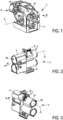
Figure 1 schematically shows in perspective an example of embodiment of a counter-connector; -
Figure 2 schematically shows in perspective an example of embodiment of a connector to be mated with the counter-connector offigure 1 ; -
Figure 3 schematically shows in perspective the connector offigure 2 viewed from another perspective angle; -
Figure 4 schematically shows in perspective a latch to be mounted on the connector offigures 2 and 3 ; -
Figure 5 schematically shows in perspective the latch offigure 4 viewed from another perspective angle; -
Figure 6 schematically shows in perspective a portion of the connector offigures 2 and 3 , on which the latch offigures 4 and 5 is mounted, the latch being in its unlocking position; -
Figure 7 is similar tofigure 6 , with a portion of the guiding and protecting wall partially removed; -
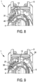
Figure 8 is a schematic transversal cross-section of the connector assembly comprising the connector offigures 2 and 3 and the counter-connector offigure 1 , the latch being in its unlocking position; -
Figure 9 is similar tofigure 8 , the latch being in its locking position; -
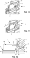
Figure 10 is a schematic perspective view of a longitudinal cross-section of the connector assembly comprising the connector offigures 2 and 3 and the counter-connector offigure 1 , the latch being in its unlocking position; -
Figure 11 is similar tofigure 10 , the latch being in its locking position; and -
Figure 12 is also a longitudinal cross-section of the connector assembly comprising the connector offigures 2 and 3 and the counter-connector offigure 1 , the latch being in its locking position. - A
connector assembly 1 is described below. Thisconnector assembly 1 comprises a connector 2 (seefigures 2 and 3 , for example) and a counter-connector 3 (seefigure 1 , for example). For example, theconnector 2 is a male connector and thecounter-connector 3 is a female connector. For example, theconnector 2 andcounter-connector 3 are two-way connectors. However, this disclosure can be transposed to one-way connectors or connectors comprising more than two ways. Thus, according to this example, theconnector 2 comprises ahousing 4 in which two electrically conductive male terminals (not shown in the figures) are housed and thecounter-connector 3 comprises ahousing 5 in which two electrically conductive female terminals (not shown in the figures) are housed. According to the example of an embodiment shown in the figures, the male terminals of theconnector 2 are housed incylindrical cavities 46. More particularly, eachcavity 46 has an outer wall 47 (seefigure 3 ) which is substantially cylindrical. - The
housings - The
connector 2 and thecounter-connector 3 are configured to be mated with each other, along a mating direction M, so that their respective terminals establish an electrical connection. In other words, the male and female terminals respectively have a contact portion essentially extending parallel to the mating direction M. To ease and secure the coupling of theconnector 2 and thecounter-connector 3, thecounter-connector 3 is equipped with a coupling aid lever 6 (also called mate assist lever). Thelever 6 is rotatably mounted, on thehousing 5 of thecounter-connector 3, about an axis of rotation A perpendicular to the mating direction M. Thelever 6 is configured to rotate about the axis of rotation A, between an open position (seefigure 1 ) in which theconnector 2 and thecounter-connector 3 are not mated, and a closed position in which theconnector 2 and thecounter-connector 3 are fully mated (figures 8 to 12 ). - The
counter-connector 3 may be originally designed to be mounted on a header (not shown) which does not necessarily include a CPA (Connector Position Assurance) device. However, in the context of the present disclosure, it is desired that theconnector 2 includes such a CPA device to ensure that theconnector 2 and thecounter-connector 3 are actually positioned relative to each other, in a position corresponding to a complete coupling and that this position is maintained locked when theconnector assembly 1 is to be functional. - Thus, without changing the existing design of the
counter-connector 3, theconnector 2 is designed with aCPA device 7 that provides the above functions (ensuring full mating of theconnector 2 andcounter-connector 3 and locking theconnector 2 andcounter-connector 3 in the fully mated position). - The
CPA device 7 comprises alatch 8 and aholder 9 for thelatch 8. Thelatch 8 is movably mounted in theholder 9. For example, theholder 9 is integral with thehousing 4 of theconnector 2. Thelatch 8 is rotatable about an axis of rotation R essentially parallel to the mating direction M between an unlocking position (Figures 2, 3 ,6, 7 ,8 and10 ) and a locking position (Figures 9 ,11 and 12 ). - The
latch 8 has alatch portion 10 and a guide portion 11 (Seefigure 4 ). Thelatch portion 10 itself has an actuatingportion 12 and alocking portion 13. - The
guide portion 11 and theholder 9 have a curved shape about the axis of rotation R which essentially follows the curvature of one of theouter walls 47 of thecavities 46. - The actuating
portion 12 is configured to be manipulated and/or pressed by an operator to move thelatch 8 from the unlocking position to the locking position, and vice versa. The actuatingportion 12 extends radially outwardly from theconnector 2, from theguide portion 11. The actuatingportion 12 is very ergonomic. Its operation is very intuitive. Thelocking portion 13 extends substantially, from the actuatingportion 12, in the mating direction M. In other words, thelocking portion 13 extends parallel to the mating direction M, in extension of the actuatingportion 12. Therefore, thelatch portion 10 is quite simple, compact, robust and easy to mold. The lockingportion 13, as described below, is configured to interfere with thelever 6 when the latter is in the closed position. - The
guide portion 11 is essentially in the form of a curved plate 14 (like a tile) which is curved around the rotation axis R of thelatch 8. Theguide portion 11 comprises CPA activating means 15 (i.e. means for activating the CPA device 7), locking means 16 (i.e. means for locking thelatch 8 in the unlocking position), and guiding and retaining means 17 (i.e. means for guiding and retaining thelatch 8 in the holder 9). - More particularly, according to an embodiment example, the
guide portion 11 comprises aflexible tab 18. Thisflexible tab 18 extends essentially over a curved portion, essentially, with the same radius of curvature as thecurved plate 14, between afree end 19 remote from the actuatingportion 12 and a joiningzone 20 closer to the actuatingportion 12. - More particularly also, according to an embodiment example, the
free end 19 is provided with an activatinglug 21 and a lockinglug 22. The activation means 15 of the CPA device thus comprises the activatinglug 21 and theflexible tab 18. The locking means 16 of thelatch 8 in the unlocking position therefore comprises the lockinglug 22 and theflexible tab 18. The activatinglug 21 extends from thefree end 19, in the mating direction M, passes through aslot 23 provided in anabutment wall 24 of the holder 9 (thisabutment wall 24 extending substantially perpendicularly to the mating direction M), and protrudes (in the mating direction M) from anouter face 25 of this abutment wall 24 (seefigure 6 ). Aclearance space 30 is provided between theflexible tab 18 and the remainder of thecurved plate 14. Thus, when a force is exerted on the activatinglug 21 in a direction opposite to the mating direction M, the flexible tab 18 (and more particularly its free end 19) can move back into theclearance space 30. - The locking
lug 22 extends from thefree end 19, substantially in a radial direction with respect to the axis of rotation R, into the interior of acavity 40 formed in the holder 9 (seefigure 7 ). The lockinglug 22 has anabutment surface 26 configured to cooperate with acounter abutment surface 27 formed on aprotrusion 28 projecting (in the opposite direction to the mating direction M) from aninner face 29 of the abutment wall 24 (seeFigure 7 ). The lockinglug 22 and theprotrusion 28 maintain thelatch 9 in the unlocking position when theabutment surface 26 is locked behind thecounter abutment surface 27. - More particularly also, according to an embodiment example, the guiding and retaining means 17 comprise a bridge 31 (see
figure 5 ). Thisbridge 31 extends in an arc above thecurved plate 14, with a radius of curvature smaller than that of thecurved plate 14. Thebridge 31 has aprojection 32. Thisprojection 32 extends in a radial direction with respect to the axis of rotation R, from anupper surface 33 of thebridge 31. Theprojection 32 has a bevelled surface 34 (seeFigure 5 ) and an abutment surface 35 (seeFigure 4 ). Theabutment surface 35 is oriented substantially in a direction opposite to the mating direction M. Theprojection 32 is configured to enter aslot 36 in a guiding and protectingwall 37 of the holder 9 (seeFigure 6 ). Theprojection 32 and thisslot 36 are configured to allow the movement of theprojection 32 into theslot 36, when thelatch 8 is moved from its locking position to its unlocking position, and vice versa. The position in theslot 36 of the projection 32 (which is visible through the slot 36) provides an index about the position (locking or unlocking position) of theCPA device 7 and itslatch 8. - According to the embodiment example described here, the
holder 9 comprises theabutment wall 24, the guiding and protectingwall 37, a slidingsurface 38 and a blocking wall 39 (seefigure 7 ). Together these elements define thecavity 40 in which the major part of theguide portion 11 of thelatch 8 is accommodated (seeFigure 8 ). As mentioned above, theabutment wall 24 extends substantially perpendicular to the mating direction M. It includes theslot 23, as well as anopening 41 configured to allow the lockingportion 13 to pass through the abutment wall 24 (seeFigure 6 ). The slidingsurface 38 may be formed on an outer face of thehousing 4 of theconnector 2. The slidingsurface 38 and thecurved plate 14 are configured to slide on each other when thelatch 8 is moved from its locking position to its unlocking position, and vice versa. The guiding and protectingwall 37 is configured to cover the major part of thecurved plate 14. More particularly, theflexible tab 18 and the lockinglug 22 are covered by the guiding and protectingwall 37. In a cross-section perpendicular to the mating direction M (seeFigures 8 and 9 ), the slidingsurface 38 and the guiding and protectingwall 37 extend over curves which are substantially parallel to each other on either side of thecavity 40. The radial distance between the slidingsurface 38 and the guiding and protectingwall 37 is greater than the height of the locking lug 22 (this height being considered to also include the thickness of the curved plate 14). Thus, the lockinglug 22 does not hinder the movement of thelatch 8 from its locking position to its unlocking position, and vice versa (except when it cooperates, in the unlocking position, with the protrusion 28). On the other hand, the radial distance between the slidingsurface 38 and the guiding and protectingwall 37 is smaller than the height of thebridge 31 and theprojection 32. However, thanks to theslot 36, thebridge 31 and theprojection 32 do not hinder the movement of thelatch 8 from its locking position to its unlocking position, and vice versa. - According to the embodiment example described here, the blocking
wall 39 is configured to cooperate with the actuatingportion 12, when thelatch 8 is in the locking position (seeFigure 9 ). - To mount the
latch 8 in theholder 9, thelatch 8 is inserted into thecavity 40 essentially parallel to the mating direction M, with the front portion of the latch 8 (i.e. the portion carrying the flexible tab 18) being presented into thecavity 40 first. As mentioned above, the height of the activatinglug 21 allows the insertion of this front portion (i.e. the flexible tab 18) between the slidingsurface 38 and the guiding and protectingwall 37. As thelatch 8 is further inserted into thecavity 40, thecurved plate 14 is further inserted between the slidingsurface 38 and the guiding and protectingwall 37, until thebridge 31 and theprojection 32 are retained at the entrance to thecavity 40. However, thebridge 31 is sufficiently flexible so that the friction of the bevelledsurface 34 on the guiding and protectingwall 37 causes it to bend, which allows it to retract under the guiding and protectingwall 37, when a sufficient force is exerted onto thelatch 8, in the mating direction M. When thebridge 31 reaches theslot 36, it can resume its original shape (without mechanical stress and without deformation). Theabutment surface 35 then cooperates with an edge of theslot 36 to prevent thelatch 8 from being removed from the holder 9 (e.g. if pulled in a direction opposite to the mating direction M). - The
connector 2 is delivered with thelatch 8 in the unlocking position. Thelatch 8 is held in this unlocking position by the co-operation of theabutment surface 26 of the lockinglug 22, with thecounter abutment surface 27 of theprotrusion 28. When thelatch 8 is in this unlocking position, an operator can see that thelatch portion 10 is properly positioned so as not to interfere with the closing of thelever 6. As already mentioned, the position of theprojection 32 in theslot 36 provides an index that can also be used to check that thelatch 8 is in the unlocking position. The position of the activatinglug 21 in theslot 23 may also allow this verification. - In order to couple the
connector 2 with thecounter-connector 3, these are presented with their coupling face facing each other. A relative movement of theconnector 2 and the counter-connector 3 parallel to the mating direction M is then carried out until thehousing 5 of thecounter-connector 3 comes to rest on theabutment wall 24. This movement is assisted by thelever 6 which then moves from its open position (allowing the coupling of theconnector 2 with the counter-connector 3) to its closed position, in which theconnector 2 and the counter-connector 3 are completely and correctly coupled and mated. According to an embodiment example of the counter-connector 3, it comprises alever 6 with ahook 42 and ahousing 5 with a latch 43 (see figures and 12). When thelever 6 is rotated to its locking position, thehook 42, which has a certain flexibility, is deformed to hook onto thelatch 43. Thus, the hook 42 (or more particularly. thelever 6 with hook 42) and thelatch 43 form the primary locking means of thelever 6 and, consequently, of theconnector assembly 1. - In the closed position of the
lever 6, thehousing 5 of the counter-connector 3 presses the activatinglug 21 in a direction opposite to the mating direction M, causing theflexible tab 18 to move back into theclearance space 30. One can note that there is no need to change the design of thecounter-connector 3 and/or to add a feature to it. It is enough to have the activatinglug 21 configured to engage a portion and/or a surface of the counter-connector 3, to unlock thelatch 8 from its unlocking position, when theconnector 2 is fully mated to thecounter-connector 3. The lockinglug 22 escapes theprotrusion 28. This releases thelatch 8 from its unlocking position. Thelatch 8 can then be moved to its locking position, in which theactuating portion 12 cooperates with the blockingwall 39, to prevent movement of thelatch 8 beyond this locking position. When thelatch 8 is in the locking position, the lockingportion 13 co-operates with thelever 6 to retain thelever 6 in the closed position. In particular, the lockingportion 13 is disposed above thehook 42 to prevent thehook 42 from deforming and releasing from thelatch 43. Thelatch 8 thus provides secondary locking means of the lever 6 (Seefigure 12 ). - In addition, the
abutment wall 24 has a reinforcingbeam 44 above theopening 41 which prevents the lockingportion 13 from moving upwards (upwards inFigure 12 ) if thelever 6 is pulled from its closed to its open position. - A ramp 45 (see
Figure 7 ) cooperates with the lockinglug 22 to hold thelatch 8 in the locking position (elastically due to the restoring force exerted by the flexible tab 18). - The position of the
projection 32 in theslot 36 also makes it possible to check that thelatch 8 is in the locking position. The position of the activating lug 21 (if still visible) in theslot 23 may also allow this verification. - Conversely, to uncouple the
connector 2 and thecounter-connector 3, thelatch 8 is moved from its locking position to its unlocking position. Thelever 6 is then released. An operator can move it from its closed position to its open position, thus causing a relative displacement of theconnector 2 and the counter-connector 3 corresponding to their unmating. - One can note that thank to its rotatable configuration, the
CPA device 7 provides several advantages such as: - its ease of handling thanks to its large gripping surfaces over the actuating
portion 12; - its simplicity of use because of its rotary movement which is very intuitive;
- the fact that it can be used with connectors for which the dimension parallel to the mating direction M must remain relatively short; indeed, CPA devices actuated, between the locking and unlocking positions, along a stroke parallel to the mating direction M require a stroke that is not required by CPA devices rotatably actuated about an axis parallel to this mating direction M;
- there is no need to change the design of the counter-connector 3 to provide the connector assembly with secondary locking means.
Claims (10)
- A connector assembly (1) comprising a connector (2) and a counter-connector (3) mated to each other parallel to a mating direction (M), wherein- the counter-connector (3) comprises primary locking means (42, 43) comprising a coupling aid lever (6) rotatable, about an axis of rotation (A) perpendicular to the mating direction (M), between an open position and a closed position, the lever (6) being in the closed position when the connector (2) and counter-connector are fully coupled,- the connector (2) comprises secondary locking means (7) movable between a locking position and an unlocking position and configured to cooperate, in the locking position, with the primary locking means (42, 43) to lock the lever (6) in the closed position, characterised in that the secondary locking means (7) comprises a latch (8) rotatable about an axis of rotation (R) parallel to the mating direction, between the unlocking position and the locking position.
- The connector assembly (1) according to claim 1, wherein the secondary locking means (7) comprises an actuating portion (12) with an actuating surface extending radially from the axis of rotation (R) and configured to be manipulated in rotation about the axis of rotation (R), by an operator to move the latch (8) from the unlocking position to the locking position, and vice versa.
- The connector assembly (1) according to claim 2, wherein the secondary locking means (7) comprises a locking portion (13) extending parallel to the mating direction (M), in extension of the actuating portion (12), the locking portion (13) blocking the lever (6) in the closed position, whereas the connector (2) and the counter-connector (3) are mated.
- The connector assembly (1) according to claim 3, wherein the secondary locking means (7) comprises a reinforcing beam (44) configured to limit a deformation of the locking portion (13) if the rotation of the lever (6) is forced from the closed position towards the open position.
- The connector assembly (1) according to any preceding claim, wherein the secondary locking means (7) comprises an activating lug (21) configured to engage the counter-connector (3), to unlock the latch (8) from its unlocking position, when the connector (2) is mated to the counter-connector (3).
- The connector assembly (1) according to any preceding claim, wherein the connector comprises a housing (4) and the secondary locking means (7) comprises locking means (22) configured to cooperate with an abutment surface (27) fixed relative to the housing (4), the cooperation of the locking means (22) with the abutment surface (27) blocking the latch (8) in the unlocking position.
- The connector assembly (1) according to claim 6, wherein the secondary locking means (7) comprises activating means (21) located on flexible means (18), the activating means (21) being configured to cooperate with the counter-connector (3) and to deflect the flexible means (18) to release the locking means (22) from the abutment surface (27), when the connector (2) and the counter-connector (3) are mated.
- Connector assembly (1) according to any preceding claim, wherein the flexible means (18) and the locking means (22) are at least partially covered by a guiding and protecting wall (37).
- The connector assembly (1) according to any preceding claim, comprising indexing means (17, 36) to visually indicate whether the secondary locking means (7) are in the unlocking position or the locking position.
- A connector (2) having a housing (4) with at least one cavity (46) for accommodating a terminal, said terminal having a contact portion extending in a mating direction (M), and secondary locking (7) being rotatably mounted on the housing (4) between a locking position and an unlocking position,
characterised in that the secondary locking means (7) comprises a latch (8) rotatable about an axis of rotation (R) parallel to the mating direction (M), between the unlocking position and the locking position.
Priority Applications (1)
| Application Number | Priority Date | Filing Date | Title |
|---|---|---|---|
| US18/654,392 US20250233357A1 (en) | 2023-01-27 | 2024-05-03 | Connector and connector assembly with a rotating connector position assurance device |
Applications Claiming Priority (1)
| Application Number | Priority Date | Filing Date | Title |
|---|---|---|---|
| EP23153725 | 2023-01-27 |
Publications (1)
| Publication Number | Publication Date |
|---|---|
| EP4407812A1 true EP4407812A1 (en) | 2024-07-31 |
Family
ID=85132948
Family Applications (1)
| Application Number | Title | Priority Date | Filing Date |
|---|---|---|---|
| EP24152238.2A Pending EP4407812A1 (en) | 2023-01-27 | 2024-01-16 | Connector and connector assembly with a rotating cpa device |
Country Status (2)
| Country | Link |
|---|---|
| US (1) | US20250233357A1 (en) |
| EP (1) | EP4407812A1 (en) |
Citations (4)
| Publication number | Priority date | Publication date | Assignee | Title |
|---|---|---|---|---|
| KR20090022372A (en) * | 2007-08-30 | 2009-03-04 | 한국단자공업 주식회사 | Connector assembly |
| US20130065412A1 (en) * | 2011-09-12 | 2013-03-14 | Yazaki Corporation | Connector engagement body |
| DE102011056556A1 (en) * | 2011-12-16 | 2013-06-20 | Tyco Electronics Amp Gmbh | Housing for an optical or electrical connector for use with and without lever and modular system with such a housing |
| US9748693B1 (en) * | 2016-02-10 | 2017-08-29 | Yazaki North America, Inc. | Connector position assurance with identification feature |
-
2024
- 2024-01-16 EP EP24152238.2A patent/EP4407812A1/en active Pending
- 2024-05-03 US US18/654,392 patent/US20250233357A1/en active Pending
Patent Citations (4)
| Publication number | Priority date | Publication date | Assignee | Title |
|---|---|---|---|---|
| KR20090022372A (en) * | 2007-08-30 | 2009-03-04 | 한국단자공업 주식회사 | Connector assembly |
| US20130065412A1 (en) * | 2011-09-12 | 2013-03-14 | Yazaki Corporation | Connector engagement body |
| DE102011056556A1 (en) * | 2011-12-16 | 2013-06-20 | Tyco Electronics Amp Gmbh | Housing for an optical or electrical connector for use with and without lever and modular system with such a housing |
| US9748693B1 (en) * | 2016-02-10 | 2017-08-29 | Yazaki North America, Inc. | Connector position assurance with identification feature |
Also Published As
| Publication number | Publication date |
|---|---|
| US20250233357A1 (en) | 2025-07-17 |
Similar Documents
| Publication | Publication Date | Title |
|---|---|---|
| EP2218149B1 (en) | Electrical connector assembly having connector position assurance device | |
| US10276977B2 (en) | Electrical connector with lever and method for operating same | |
| KR100875066B1 (en) | Lever type electrical connector with slide member with double latching and feedback function | |
| US5681184A (en) | Connector with secondary locking and coupling mechanisms | |
| US8297992B2 (en) | Electrical connector assembly having locking device | |
| JP2002352903A (en) | Lever-type connector | |
| EP0889555B1 (en) | Electrical connector assembly | |
| EP1571734B1 (en) | Connector apparatus with a mating detecting member called connector position assurance | |
| EP0976175B1 (en) | Connector with secondary locking and coupling mechanism | |
| EP2863490A1 (en) | Connector assembly with CPA member | |
| KR20210001980A (en) | Electrical connector with mate assist having feedback | |
| US20250233357A1 (en) | Connector and connector assembly with a rotating connector position assurance device | |
| EP2362974B1 (en) | Mate-assist with an off-centre lever | |
| EP3975345A1 (en) | Connector assembly comprising module with integrated terminal position assurance means | |
| EP1050087B1 (en) | Connector arrangement with an actuating slide | |
| JP7719887B2 (en) | plug socket | |
| EP0971454B1 (en) | Electrical connector with actuating device | |
| JP4158686B2 (en) | Lock structure | |
| EP4726936A1 (en) | Right-angle electrical connector with a mate assist system | |
| JP7715473B2 (en) | Connector with connector position assurance mechanism | |
| EP4340138A1 (en) | Secured high power connector assembly and process of assembly | |
| US20260051700A1 (en) | Electrical connector assembly | |
| EP4459812A1 (en) | Dual locking system | |
| JP2024170307A (en) | Housing assemblies for connectors, connectors and connection assemblies | |
| CN117999711A (en) | Connectors and connector components |
Legal Events
| Date | Code | Title | Description |
|---|---|---|---|
| PUAI | Public reference made under article 153(3) epc to a published international application that has entered the european phase |
Free format text: ORIGINAL CODE: 0009012 |
|
| STAA | Information on the status of an ep patent application or granted ep patent |
Free format text: STATUS: THE APPLICATION HAS BEEN PUBLISHED |
|
| AK | Designated contracting states |
Kind code of ref document: A1 Designated state(s): AL AT BE BG CH CY CZ DE DK EE ES FI FR GB GR HR HU IE IS IT LI LT LU LV MC ME MK MT NL NO PL PT RO RS SE SI SK SM TR |
|
| RAP3 | Party data changed (applicant data changed or rights of an application transferred) |
Owner name: APTIV TECHNOLOGIES AG |
|
| STAA | Information on the status of an ep patent application or granted ep patent |
Free format text: STATUS: REQUEST FOR EXAMINATION WAS MADE |
|
| 17P | Request for examination filed |
Effective date: 20250121 |