EP4407786A2 - Dualpolarisierte hochleistungsantennenspeisekette - Google Patents
Dualpolarisierte hochleistungsantennenspeisekette Download PDFInfo
- Publication number
- EP4407786A2 EP4407786A2 EP24168516.3A EP24168516A EP4407786A2 EP 4407786 A2 EP4407786 A2 EP 4407786A2 EP 24168516 A EP24168516 A EP 24168516A EP 4407786 A2 EP4407786 A2 EP 4407786A2
- Authority
- EP
- European Patent Office
- Prior art keywords
- horn
- cross
- polarizer
- feed
- interest
- Prior art date
- Legal status (The legal status is an assumption and is not a legal conclusion. Google has not performed a legal analysis and makes no representation as to the accuracy of the status listed.)
- Pending
Links
Images




Classifications
-
- H—ELECTRICITY
- H01—ELECTRIC ELEMENTS
- H01P—WAVEGUIDES; RESONATORS, LINES, OR OTHER DEVICES OF THE WAVEGUIDE TYPE
- H01P1/00—Auxiliary devices
- H01P1/16—Auxiliary devices for mode selection, e.g. mode suppression or mode promotion; for mode conversion
- H01P1/161—Auxiliary devices for mode selection, e.g. mode suppression or mode promotion; for mode conversion sustaining two independent orthogonal modes, e.g. orthomode transducer
-
- H—ELECTRICITY
- H01—ELECTRIC ELEMENTS
- H01Q—ANTENNAS, i.e. RADIO AERIALS
- H01Q13/00—Waveguide horns or mouths; Slot antennas; Leaky-waveguide antennas; Equivalent structures causing radiation along the transmission path of a guided wave
- H01Q13/02—Waveguide horns
- H01Q13/025—Multimode horn antennas; Horns using higher mode of propagation
- H01Q13/0258—Orthomode horns
-
- H—ELECTRICITY
- H01—ELECTRIC ELEMENTS
- H01Q—ANTENNAS, i.e. RADIO AERIALS
- H01Q19/00—Combinations of primary active antenna elements and units with secondary devices, e.g. with quasi-optical devices, for giving the antenna a desired directional characteristic
- H01Q19/06—Combinations of primary active antenna elements and units with secondary devices, e.g. with quasi-optical devices, for giving the antenna a desired directional characteristic using refracting or diffracting devices, e.g. lens
- H01Q19/08—Combinations of primary active antenna elements and units with secondary devices, e.g. with quasi-optical devices, for giving the antenna a desired directional characteristic using refracting or diffracting devices, e.g. lens for modifying the radiation pattern of a radiating horn in which it is located
-
- H—ELECTRICITY
- H01—ELECTRIC ELEMENTS
- H01Q—ANTENNAS, i.e. RADIO AERIALS
- H01Q13/00—Waveguide horns or mouths; Slot antennas; Leaky-waveguide antennas; Equivalent structures causing radiation along the transmission path of a guided wave
- H01Q13/02—Waveguide horns
- H01Q13/0208—Corrugated horns
-
- H—ELECTRICITY
- H01—ELECTRIC ELEMENTS
- H01Q—ANTENNAS, i.e. RADIO AERIALS
- H01Q19/00—Combinations of primary active antenna elements and units with secondary devices, e.g. with quasi-optical devices, for giving the antenna a desired directional characteristic
- H01Q19/10—Combinations of primary active antenna elements and units with secondary devices, e.g. with quasi-optical devices, for giving the antenna a desired directional characteristic using reflecting surfaces
Definitions
- the present disclosure relates generally to antennas, and more specifically to antenna feed chains.
- RF antennas may be suitable for transmitting, receiving, or transmitting and receiving a signal.
- RF antennas may include a feed horn and a polarizer.
- a feed horn and a polarizer comprise an antenna feed chain.
- the cross-polarization performance of an antenna feed chain may impact the antennas performance.
- Antenna performance may impact the performance of a communication system using the antenna. Accordingly, antenna performance may impact the ability of a communication to successfully send, successfully receive, or successfully send and receive signals.
- an antenna feed chain includes a feed horn having a first cross-polarization performance over a solid angle of interest and a frequency band of interest.
- the antenna feed chain includes a polarizer having a second cross-polarization performance over the frequency band of interest.
- the polarizer is coupled to the feed horn.
- the first cross-polarization performance of the feed horn compensates for the second cross-polarization performance of the polarizer over the solid angle of interest and the frequency band of interest.
- a method of designing an antenna feed chain includes determining an initial design for each of a feed horn having a first cross-polarization performance and a polarizer having a second cross-polarization performance. The method also includes using the first cross-polarization performance of the feed horn to compensate for the second cross-polarization performance of the polarizer over a frequency band of interest. Additionally, the method includes coupling the feed horn to the polarizer to form the antenna feed chain.
- an antenna feed chain includes a feed horn and a polarizer coupled to the feed horn.
- the feed horn has a cross-polarization performance over an angle of interest and a frequency band of interest (CP performance) that is worse than a reference feed horn CP performance of a reference feed horn (of the same kind, aperture diameter, and length as the feed horn).
- the antenna feed chain nonetheless has a CP performance that is better than a reference antenna feed chain CP performance of a reference antenna feed chain comprising the reference feed horn and the polarizer.
- An antenna feed chain may include a feed horn and a polarizer.
- the feed horn and the polarizer may each have a cross-polarization performance.
- a combination of the feed horn and the polarizer may have a cross-polarization performance.
- a feed horn may be designed to maximize a performance characteristic such as cross-polarization performance.
- a polarizer may be designed to maximize a performance characteristic such as cross-polarization performance. The feed horn and the polarizer may then be coupled together to form an antenna feed chain.
- such a combination may generally not provide for the best performance of the feed chain, i.e., as defined by the chosen performance characteristic, e.g., cross-polarization performance. Rather, independently "optimizing" the design of the each component may result in, for example, the poorest performance of each component occurring at or near the same frequencies. Accordingly, frequency ranges with poor performance may have those poor performances add together to provide degraded performance for the combined device at those frequencies.
- antenna performance may impact the ability of a communication to successfully send, successfully receive, or successfully send and receive signals.
- it may be beneficial to improve cross-polarization performance in an antenna feed chain.
- an antenna feed chain may provide improved performance over a wide bandwidth.
- a feed horn of an antenna feed chain may be designed to compensate for the performance of a polarizer of the feed chain.
- An antenna feed chain includes a feed horn having a first cross-polarization performance over a solid angle of interest and a frequency band of interest.
- a solid angle is a measure of the amount of the field of view from some particular point that a given object covers. That is, the solid angle may be a measure of how large the object appears to an observer looking from that point, i.e., the apex.
- the antenna feed chain also includes a polarizer having a second cross-polarization performance over the frequency band of interest. The polarizer is coupled to the feed horn. The first cross-polarization performance of the feed horn compensates for the second cross-polarization performance of the polarizer over the solid angle of interest and the frequency band of interest.
- a polarizer of an antenna feed chain may be designed to compensate for the performance of a feed horn of the feed chain.
- the design of the feed horn and the design of the polarizer interact such that performance of the feed chain may be set by the combination of each design.
- the design of the feed horn may compensate for the performance of a polarizer and the design of the polarizer may compensate for the performance of a feed horn.
- designing a feed horn to compensate for a polarizer may include designing a polarizer to compensate for a feed horn.
- Designing a polarizer to compensate for a feed horn may include designing a feed horn to compensate for a polarizer.
- designing a feed horn to compensate for a polarizer and/or designing a polarizer to compensate for a feed horn may include iteratively modifying one or more of the feed horn and or the polarizer.
- the feed horn may be designed such that cross-polarization performance of the feed horn may be higher at frequencies where the cross-polarization performance of the polarizer is lower.
- the feed horn may be designed such that the cross-polarization performance of the feed horn may be lower at frequencies where the cross-polarization performance of the polarizer is higher.
- the cross-polarization performance of the feed chain may be improved, e.g., over frequencies and/or phases of interest.
- the cross-polarization performance of the antenna feed chain may be "collectively" maximized over the operating frequency band(s) of the antenna by leveling out the cross-polarization performance across the operating frequency band(s).
- the maximum of the performance metric denotes a relative maximum value over the operating frequency band(s) of the antenna or an individual component.
- the performance metric may vary from embodiment to embodiment.
- performance metric refers to any metric for which a higher value indicates better performance.
- the maximum of the "performance metric” is achieved by minimizing a parameter for which a lower value indicates better performance.
- the maximum cross-polarization performance is achieved by minimizing cross-polarization. Examples are described herein that use cross-polarization performance as the performance metric.
- performance metrics include, but are not limited to return loss, port-to-port isolation, axial ratio, higher-order mode suppression, and/or radiation characteristics such as, peak co-polarized gain, sidelobe level suppression, beam shape, minimum cross-polarized radiation within a solid angle or other radiation characteristics.
- FIG. 1 is a diagram illustrating an example of an antenna feed chain 100 as described herein.
- the example antenna feed chain 100 includes a feed horn 102 (also referred to as a "horn" herein) and a polarizer 104.
- the feed horn 102 includes a lens 106.
- the feed horn 102 may be a lens horn 108.
- the polarizer 104 may be a septum polarizer ortho-mode transducer (SP/OMT).
- SP/OMT septum polarizer ortho-mode transducer
- the feed horn 102 may include an aperture at a first end and a second end opposite the first end.
- the polarizer 104 may include a first end and a second end.
- the second end of the feed horn 102 is connected to the first end of the polarizer 104 for passing signals between the aperture of the feed horn and an input/output at the second end of the polarizer.
- a waveguide is provided coupling the feed horn to the polarizer, the waveguide may be terminated at the feed horn and may be configured to have cross-sectional dimensions to predominantly propagate a dominant field mode. Accordingly, the systems and methods described herein may help eliminate unneeded or unwanted modes in favor of a dominant field mode.
- a reflector (not shown) may be configured to reflect signals from the feed horn 102.
- an antenna feed chain 100 may include a feed horn 102 having a first cross-polarization performance over a solid angle of interest and a frequency band of interest.
- the antenna feed chain 100 may also include a polarizer 104 having a second cross-polarization performance over the frequency band of interest.
- the polarizer may be coupled to the feed horn.
- the first cross-polarization performance of the feed horn may compensate for the second cross-polarization performance of the polarizer over the solid angle of interest and the frequency band of interest.
- the antenna feed chain 100 includes the lens horn 108 and the SP/OMT
- the systems and methods described herein may be applied to any horn and any polarizer.
- the feed horn may a pyramidal horn, a sectoral horn, an E-plane horn, an H-plane horn, a sectoral horn flared in the direction of the magnetic or H-field in a waveguide, a conical horn, an exponential horn, a corrugated horn, a dual-mode conical horn, a diagonal horn, a ridged horn, a septum horn, or aperture-limited horn, to name a few examples.
- the feed horn when the feed horn is corrugated, the feed horn may be axial corrugated or otherwise corrugated.
- the feed horn may include at least one of a smoothly flared horn, a discontinuous flared horn, or a combination of the smoothly flared horn and the discontinuous flared horn.
- the polarizer 104 may be a linear polarizer, an absorptive polarizer, a beamsplitting polarizer, or another polarizer.
- the polarizer may be a septum polarizer.
- the feed horn in the example of FIG. 1 includes a lens and an axially-corrugated horn. In other embodiments, the antenna feed chain may be different.
- the lens 106 may be omitted.
- the lens 106 may be useful, particularly in situations where the application would otherwise necessitate a physically large standalone horn.
- the lens horn may achieve desired RF characteristics, such as peak gain, of the standalone horn in an appreciably smaller volume.
- a feed horn of a modest size provides a portion of the desired gain
- a lens, located in, or near, the feed horn aperture provides the remaining part of the desired gain.
- design modifications of the lens 106 or lens horn 108 may be preferable to design modifications of the polarizer 104.
- Design modifications of the lens 106 or lens horn 108 may be preferable to design modifications of the polarizer 104 because of the extra degrees of freedom in the design of the lens 106 or lens horn 108.
- a lens horn 108 may be preferable to a standalone feed horn 102.
- the lens horn 108 may be preferable to a standalone feed horn 102 because of the extra degrees of freedom and more dimensions of the design space, that the lens horn 108 offers in comparison with the standalone feed horn 102.
- the lens 106 brings in the lens' two surfaces. The surfaces may be shaped toward achieving performance characteristics that a standalone feed horn 102 may have difficulty achieving, e.g., the lens may be used to form the shape of the main lobe beyond what is feasible with the standalone feed horn 102.
- the antenna feed chain includes the septum polarizer/ortho-mode transducer (SP/OMT) (polarizer 104).
- the type of polarizer may be different and may include a dedicated OMT.
- the SP/OMT (polarizer 104) may provide the following benefits, such as component simplicity.
- the SP/OMT may provide the functionality of a polarizer and an OMT in a single device.
- Other combinations of a dedicated polarizer and a dedicated OMT may be more complex, bulkier, heavier and considerably more expensive to mass-produce, in some examples.
- SP/OMT housings may be produced by die casting in split block, and the septa may be stamped from sheet metal in some examples.
- the SP/OMT may have some limitations due to wave propagation in waveguides, however.
- the two dominant modes in the square waveguide, TE 10 , and TE 01 may have the same cutoff frequency, f c1 .
- the waveguide attenuation approaches infinity.
- a practically achievable relative bandwidth for the septum polarizer in the square waveguide operating with dominant modes only is about 15%. (The relative bandwidth of the septum polarizer in the circular waveguide operating with dominant modes only is even smaller.)
- the composite bandwidth of 17.3-31.0 GHz corresponds to a relative bandwidth of 56.7%.
- a composite bandwidth corresponding to a relative bandwidth of 56.7% implies that the excitation of higher-order modes in the SP/OMT may be inevitable above the 17.3-21.2 GHz band.
- FIG. 2 is a diagram 200 illustrating an example of computed excitation levels of higher-order modes in an example septum polarizer/OMT (polarizer 104).
- Frequency in GHz runs along the x-axis.
- Magnitude of S-parameters in dB run along the y-axis.
- TM11 dashed line
- TE11 solid line
- the cutoff frequency for TE11 and TM11 is noted as well as the receive band and the transmit band for an example communication.
- the space segment of a K a -band satellite communication systems transmits in the lower (17.7-21.2 or 17.3-21.2 GHz) frequency band and receives in the higher (27.5-31.0 GHz) frequency band.
- the frequency allocation may be opposite.
- the regulatory requirements on the operation of satellite communication systems apply to the transmit functionality, with the goal of ensuring that one piece of equipment does not interfere with another piece of equipment.
- the goal of ensuring that equipment does not interfere means that the ground segment equipment may be particularly adversely affected by the excitation of higher-order modes in the ground segment equipment's SP/OMT's in the transmit band.
- the electromagnetic field distributions of the TE 11 and TM 11 modes in the square waveguide compared to those of the TE 10 and TE 01 modes are such that the excitation of the higher-order modes in the SP/OMT increases the cross-polarized field components of the device, and hence also the overall feed chain.
- Increasing the cross-polarized field components of the device and hence also the overall feed chain may make it more difficult to achieve adequate cross-polarized radiation performance in the ground segment feed chains and overall antenna systems.
- the regulators for reasons of avoiding interference with other satellite operators, may set limits for the off-boresight cross-polarized radiation of antennas, and the interference-free operation of one's own satellite may dictate a limit on the cross-polarized radiation at the antenna boresight. Accordingly, limiting the cross-polarized radiation of ground segment satellite communication antennas is particularly important.
- Waveguides are generally operated with dominant modes only. That is, cross-sectional dimensions of the waveguide are chosen such that only the dominant field mode, e.g., TE 10 or TE 11 in the rectangular or circular waveguide, respectively, may propagate in the waveguide in a desired operating frequency band, e.g., the waveguide's cross-sectional dimensions are too small for supporting propagation of higher-order modes.
- the dominant field mode e.g., TE 10 or TE 11 in the rectangular or circular waveguide, respectively.
- the waveguide When a waveguide is required to radiate to free space or illuminate a reflector, for example, while providing a larger peak gain than that of the open-ended waveguide, the waveguide is terminated with a feed horn (e.g., feed horn 102 of FIG. 1 ).
- the feed horn is a waveguiding structure that flares out to an aperture that is sized to provide a required peak gain.
- the feed horn flares open - either gradually (smoothly) or in steps (discontinuities) or combinations thereof - the increased cross-section of the feed horn enables the generation of higher-order field modes in the feed horn.
- the modes listed in Table 1 get excited in the feed horn, depending on the diameter of the feed horn's radiating aperture. Exciting the modes of Table 1 in the feed horn as described above, at a point along the feed horn where the feed horn's diameter is 2.5 wavelengths, for example, the TM 11 , TE 12 , and TM 12 modes are excited in addition to the dominant (TE 11 ) mode, since the cut-off guide diameter of these modes is smaller than 2.5 wavelengths.
- Table 1 is a table of dominant and higher-order modes in circular waveguides. Because cut-off guide diameter increases with the mode order, the excitation amplitudes and phases of the higher-order modes in the feed horn may be controlled by shaping the inside profile of the feed horn. When, for example, a higher content of a field mode is desired in the radiating aperture of the feed horn, the feed horn may be shaped to (1) increase the excitation amplitude of the mode in the feed horn and (2) guide the mode to the radiating aperture (as opposed to trapping the mode by preventing the mode from propagating or converting the mode to another farther down the length of the feed horn). Conversely, the excitation amplitude of a mode that is not wanted in the feed horn aperture may be minimized by reshaping the feed horn profile.
- a feed chain may include a polarizer and a feed horn, and the feed chain may be designed the following way:
- FIG 3 is a diagram 300 illustrating an example amplitude of cross-polarized radiation of a conventionally designed feed chain. Frequency runs along the x-axis. Amplitude of the cross-polarized radiation runs along the y-axis. The amplitude of the cross-polarized radiation, such as the maximum cross-polarized radiation within a solid angle of interest (which, for example, may correspond to the illumination cone of a reflector that the feed chain illuminates), of the feed chain designed conventionally may look like that illustrated in FIG. 3 . In FIG.
- the total cross-polarized radiation (dashed line) 302 includes two contributions: the cross-polarized radiation of the polarizer (dashed line) 306 and the cross-polarized radiation of the feed horn (dash-dotted line) 304.
- the total cross-polarized radiation 302 of the feed chain results from the vector addition of the two contributions.
- the feed horn 102 as described herein may be designed the following way:
- the feed horn 102 may be optimized in the full feed chain (antenna feed chain 100 of FIG. 1 ) arrangement, e.g., including the imperfect polarizer 104.
- an antenna feed chain 100 may include a feed horn 102 having a first cross-polarization performance over a solid angle of interest and a frequency band of interest.
- the antenna feed chain 100 may also include a polarizer 104 having a second cross-polarization performance over the frequency band of interest.
- the polarizer may be coupled to the feed horn.
- the first cross-polarization performance of the feed horn may compensate for the second cross-polarization performance of the polarizer over the solid angle of interest and the frequency band of interest.
- the compensation may be due to changing (1) the shapes of the lens surfaces, (2) the position of the lens, and/or (3) all, or a subset of, dimensions of the feed horn. Any or all of these physical changes may help optimize or improve the cross-polarization performance of the full feed chain.
- the purpose of the optimization/compensation-changes may be to distribute the cross-polarization properties of the feed horn 102 unevenly across the operating frequency bands, so that the feed horn 102 vector-adds only minimal cross-polarized radiation at the frequencies where the polarizer 104 is the least polarization-clean, e.g., has the lowest polarization performance (may be a relative or local low) at the price of vector-adding more cross-polarized radiation at the frequencies where the polarizer 104 is the most polarization-clean, e.g., has the highest polarization performance (may be a relative or local high).
- the design process may yield an antenna feed chain 100 with a fairly leveled cross-polarization performance across the operating frequency bands of the antenna. ( See FIGS. 4 and 5 )
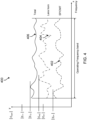
- FIG. 4 is a diagram 400 illustrating an example amplitude of cross-polarized radiation of a feed chain designed according to the systems and methods described herein. Frequency runs along the x-axis. Amplitude of the cross-polarized radiation runs along the y-axis. As illustrated in FIG. 4 , the amplitude of cross-polarized radiation (e.g., maximum cross-polarized radiation within an illumination cone of reflector) of a feed chain 100 may include the vector summation of the cross-polarized contribution from polarizer 104 (see dashed line 402) plus the cross-polarized contribution from the feed horn 102 (see dash-dot line 404). The total cross-polarized radiation of the feed chain 100 may be represented by solid line 406.
- FIG. 4 An example "fairly leveled" cross-polarization is illustrated in FIG. 4 .
- the cross-polarized radiation from the polarizer 104 may be the same as that in FIG. 3 .
- the polarizer 104 may be optimized relative to the feed chain.
- the feed horn 102 may be synthesized differently than the conventional design, the cross-polarized radiation produced by the feed horn 102 may differ from that in FIG. 3 .
- the cross-polarized radiation produced by the feed horn 102 may feature higher local maxima (
- the maximum amplitude of the total cross-polarized radiation of the feed chain may be lower (
- the amplitude may be more leveled than that in FIG. 3 .
- the difference between the highest cross-polarization value and the lowest cross-polarization value over the operating frequency band may be smaller.
- the standard deviation for the cross-polarization values over the operating frequency band of the solid angle of interest may be lower.
- the feed horn 102 synthesized according to the principles of the present disclosure may include (1) manipulating the amplitudes and phases of the field modes excited and guided in the lens horn and (2) exploiting the property of vector addition to lower the amplitude of the total cross-polarized radiation when two vectors are out of phase or close to out of phase.
- transmit-band performance of the feed chain may be given carefully chosen priority over performance in the receive band.
- the goal of such optimization is to produce a feed chain design that leads to an antenna that is compliant with regulatory requirements, which apply only in the transmit band, yet has adequate RF performance also in the receive band.
- the design process may be different than the example steps described above.
- the step [B4] may include that the feed horn 102 and the polarizer 104 may both be optimized in the full feed chain arrangement, i.e., including the polarizer.
- the feed horn 102 and the polarizer 104 may both be optimized in the full feed chain arrangement, i.e., including the polarizer.
- one or more of the following features may be modified to change the characteristics of the polarizer: (1) the shapes of the lens surfaces, (2) the position of the lens, (3) all, or a judiciously chosen subset of, dimensions of the feed horn, and (4) all, or a judiciously chosen subset of, dimensions of the polarizer may then be optimized in the full feed chain arrangement.
- the purpose of the optimization may be to distribute the cross-polarization properties of the lens horn 108 unevenly across the operating frequency bands, so that the lens horn 108 adds only minimal cross-polarized radiation at the frequencies where the polarizer is the least polarization-clean, at the price of adding more cross-polarized radiation at the frequencies where the polarizer is the most polarization-clean.
- the design process may yield a feed chain with fairly level cross-polarization performance across the operating frequency bands of the antenna.
- FIG 5 is a diagram of the examples of FIGS. 3 and 4 overlaid together to illustrate a plot of the amplitude of cross-polarized radiation of a feed chain designed conventionally overlaid on a plot of the amplitude of cross-polarized radiation of a feed chain designed according to the systems and methods described herein.
- the total cross-polarized radiation 302 includes two contributions: the cross-polarized radiation of the polarizer (see dashed line 306) and the cross-polarized radiation of the feed horn (see dash-dotted line 304).
- the total cross-polarized radiation 302 of the feed chain results from the vector addition of the two contributions. As illustrated in FIGS.
- the amplitude of cross-polarized radiation of a feed chain 100 may include the vector summation of the cross-polarized contribution from polarizer 104 (see dashed line 402) plus the cross-polarized contribution from the feed horn 102 (see dash-dot line 404).
- the total cross-polarized radiation of the feed chain 100 may also be represented by solid line (e.g., solid line 406).
- the improvement in cross-polarized radiation of the feed chain may be defined as the maximum amplitude of the total cross-polarized radiation (
- the cross-polarization performance of an antenna feed chain may impact the antennas performance. Accordingly, cross-polarization performance of an antenna feed chain may impact the performance of a communication system using the antenna. Thus, antenna performance may impact the ability of a communication to successfully send, successfully receive, or successfully send and receive signals. Accordingly, lowering total cross-polarized radiation may be beneficial to improve cross-polarization performance in an antenna feed chain.
- the feed chain 100 may perform better than a feed chain designed conventionally at least because the maximum amplitude of the total cross-polarization radiation of the feed chain 100 in a frequency band of interest may be lower than the maximum amplitude of the total cross-polarization radiation of the feed chain designed conventionally in the frequency band of interest.
- the improvement may be in that the total cross-polarized radiation of the feed chain 100, represented by solid line 406, is much "flatter” as compared to the total cross-polarized radiation 302 (dashed line) that may represent total cross-polarization radiation of a conventional feed chain.
- being flatter may be defined as a case when the amplitude of the cross-polarized radiation of the antenna feed chain has a lower standard deviation than the amplitude of the cross-polarization of an antenna feed chain that does not compensate for the cross-polarization of the polarizer.
- an absolute difference between the minimum amplitude and maximum amplitude of the total cross-polarized radiation for the antenna feed chain with compensation may be lower than that for a conventionally designed feed chain ( ⁇ E for dashed line 302).
- the performance of a first component may have a certain variation.
- a first component e.g., a polarizer
- the design of the polarizer may be fixed, as indicated by the single dashed line 306, 402.
- the performance of a second component e.g., a horn, may have certain variations, depending on the particular design of the lens horn.
- the lens horn performance represented by dash-dotted line 304 may be designed to have a low cross-polarized radiation for the individual component, e.g., the lens horn alone may have a low cross-polarized radiation.
- the lens horn may be designed to compensate for the polarizer.
- areas of generally good performance of the second component may be selected or designed to correspond to areas of generally not as good performance by the first component.
- the best performance of the second component may correspond to the worst performance of the first component.
- the cross-polarization radiation of the first component may have a certain range of values over an operating frequency.
- the design of the polarizer may be fixed.
- the cross-polarization radiation of the second component e.g., a horn, may have a certain range of values, depending on the particular design of the horn. (See, for example, lines 304, 404.)
- the lens horn performance represented by dash-dotted line 304 may be designed to have a low cross-polarized radiation for the individual component, e.g., the lens horn alone.
- the lens horn may be designed to compensate for the polarizer. Accordingly, because of the compensation, e.g., areas of generally good performance selected to correspond to areas of generally not as good performance, the range of values of the total (solid line 406) may have a much lower range of values as compared to the range of values of the total (dashed line 302). For example, an absolute difference between the minimum amplitude and maximum amplitude of the total cross-polarized radiation for the antenna feed chain with compensation ( ⁇ E for solid line 406) may be lower than that for a conventionally designed feed chain ( ⁇ E for dashed line 302).
- the polarizer may be fixed and the lens horn may vary. It will be understood that in another example, the lens horn may be fixed and the polarizer may vary. Furthermore, in some examples, the design may be iterative. For example, initially, the polarizer may be fixed and the lens horn may be varied. Then, the updated lens horn may be fixed and the polarizer may be varied. The iterations may be performed a number of times.
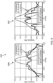
- FIG. 6 is a diagram 600 illustrating an example of receive performance of a feed chain designed as described herein as compared to a feed chain designed a conventional way.
- FIG. 6 includes typical receive-band far-field gain radiation patterns.
- the diagram 600 includes receive plots of amplitude in dB for examples of both conventional feed chain designs 602 and designs according to the systems and methods described herein 604 over spatial angles from -90.0 degrees to +90.0 degrees. The amplitude is along the y-axis and the angles measured from the feed chain boresight are along the x-axis.
- the receive plots feature lower cross-polarized radiation for a feed chain designed according to the systems and methods described herein as compared to conventional designs.
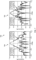
- FIG. 7 is a diagram 700 illustrating an example of transmit performance of a feed chain 704 designed as described herein as compared to a feed chain 702 designed a conventional way.
- FIG. 7 includes typical transmit-band far-field gain radiation patterns.
- the diagram 700 includes transmit plots of amplitude in dB for examples of both conventional feed chain designs and designs according to the systems and methods described herein over spatial angles from -90.0 degrees to +90.0 degrees. The amplitude is along the y-axis and the angles measured from the feed chain boresight are along the x-axis.
- the transmit plots feature lower cross-polarized radiation for a feed chain designed according to the systems and methods described herein as compared to conventional designs.
- FIG. 8 is a flow chart for an example method 800 disclosed herein.
- the example method 800 is a method of designing an antenna feed chain.
- the method includes determining an initial design for each of a feed horn having a first cross-polarization performance and a polarizer having a second cross-polarization performance (802).
- an initial design may attempt to optimize or select adequate design parameters for both the feed horn and the polarizer.
- Optimizing or selecting adequate design parameters for the individual feed horn and polarizer may each be based on maximizing or increasing some indication of performance for the design of the individual component (such as cross-polarization performance as described herein).
- the systems and methods described herein may also be applied to one or more indication of performance discussed herein, or generally to other indications of performance of an antenna system.
- the method 800 may further include using the first cross-polarization performance of the feed horn to compensate for the second cross-polarization performance of the polarizer over a solid angle of interest and a frequency band of interest (804).
- the feed horn 102 may be optimized in the full feed chain (antenna feed chain 100 of FIG. 1 ). This may involve deviating from the initial design of the feed horn.
- the feed horn 102 may have a first cross-polarization performance over a solid angle of interest and a frequency band of interest. But the subsequent design may result in the feed horn having a second cross-polarization performance over the solid angle of interest and the frequency band of interest.
- the new, second, cross-polarization performance of the feed horn may compensate for a cross-polarization performance of the polarizer over the frequency band of interest. Stated another way, the subsequent design may degrade the cross-polarization performance characteristic of the feed horn from that of the initial design, standing alone, but at the same time improve the cross-polarization performance characteristic of the antenna feed chain.
- using the first cross-polarization performance of the feed horn to compensate for the second cross-polarization performance of the polarizer over a frequency band of interest may include using the cross-polarization performance of the polarizer to compensate for the cross-polarization performance of the feed horn over a solid angle of interest and a frequency band of interest.
- an initial design of one or more of the feed-horn or the polarizer may be modified improve the performance of the combination of the feed horn and the polarizer coupled together.
- optimize generally refers to improving the design of a component (e.g., the feed horn or the polarizer) or a group of components (e.g., the feed horn coupled to the polarizer) based on some improvement of one or more selected indicators of performance for the particular component (e.g., the feed horn or the polarizer) or group of components (e.g., the feed horn and the polarizer coupled together).
- Optimizing does not necessarily mean creating the best possible design, but rather, refers to increasing relative performance of the design using the systems and methods described herein.
- the systems and methods described herein may also be applied to one or more indication of performance discussed herein, or generally to other indications of performance of an antenna system.
- the method 800 further includes coupling the feed horn to the polarizer to form the antenna feed chain (806).
- the first cross-polarization performance of the feed horn and the second cross-polarization performance of the polarizer are such that the feed horn and the polarizer cooperate in providing improved cross-polarization performance of the antenna feed chain when the polarizer is coupled to the feed horn.
- the improved cross-polarization performance is relative to an antenna feed chain having a feed horn that has not been configured to compensate for the polarizer over the frequency band of interest.
- an improvement (as determined by a selected indicator of performance) of the combined components when coupled together is the goal of the systems and methods described herein.
- method 800 may include coupling an ortho-mode transducer to the polarizer (step 808). Accordingly, the systems and methods described herein may be applied to a polarizer, e.g., coupled to a lens horn.
- the maximal amplitude of cross-polarized radiation of the antenna feed chain within the solid angle of interest and over the frequency band of interest is smaller based on the feed horn being configured to compensate for the cross-polarization of the polarizer than the maximum amplitude of cross-polarized radiation of the antenna feed chain that does not have the feed horn configured to compensate for the cross-polarization of the polarizer.
- an amplitude of cross-polarized radiation of the antenna feed chain, within the solid angle of interest and over the frequency band of interest, is flatter within the solid angle of interest and over the frequency band of interest, based on the feed horn being configured to compensate for the cross-polarization of the polarizer than the amplitude of cross-polarized radiation of the antenna feed chain that does not have the feed horn configured to compensate for the cross-polarization of the polarizer.
- an amplitude of cross-polarized radiation of the antenna feed chain being flatter comprises the amplitude of the cross-polarized radiation of the antenna feed chain having a lower standard deviation than the amplitude of the cross-polarization of an antenna feed chain that does not compensate for the cross-polarization of the polarizer.
- method 800 further includes providing a lens coupled to the feed horn (step 810) and configuring both the lens and the feed horn to compensate for the cross-polarization of the polarizer (step 812).
- a lens may be used to improve the design.
- the first cross-polarization performance of the feed horn 102 and the second cross-polarization performance of the polarizer 104 are such that the feed horn 102 and the polarizer 104 cooperate in providing an increase in cross-polarization performance when the polarizer 104 is coupled to the feed horn 102.
- polarizer 104 is an SP/OMT.
- the polarizer may be a combination of a separate ortho-mode transducer coupled to the polarizer.
- the maximum amplitude of cross-polarized radiation of the antenna feed chain 100 is lower within the solid angle of interest and over the frequency band of interest, based on the feed horn 102 being configured to compensate for the cross-polarization of the polarizer than the maximum amplitude of cross-polarized radiation of an antenna feed chain that does not have the feed horn configured to compensate for the cross-polarization of the polarizer. ( See FIGS. 4 and 5 .)
- an antenna feed chain comprises: a feed horn; and a polarizer coupled to the feed horn, the feed horn having a cross-polarization performance over an angle of interest and a frequency band of interest (XP performance) that is worse than a reference feed horn XP performance of a reference feed horn (of the same kind, aperture diameter, and length as the feed horn).
- the antenna feed chain nonetheless has a XP performance that is better than a reference antenna feed chain XP performance of a reference antenna feed chain comprising the reference feed horn and the polarizer.
- worse means that the maximum amplitude of the feedhorn cross-polarized radiation (
- a numerical range of "about 1 to 5" should be interpreted to include not only the explicitly recited values of about 1 to about 5, but also include individual values and sub-ranges within the indicated range. Thus, included in this numerical range are individual values such as 2, 3 and 4 and sub-ranges such as 1-3, 2-4 and 3-5, etc. This same principle applies to ranges reciting only one numerical value (e.g., "greater than about 1") and should apply regardless of the breadth of the range or the characteristics being described.
- a plurality of items may be presented in a common list for convenience. However, these lists should be construed as though each member of the list is individually identified as a separate and unique member.
- the disclosure comprises the following items:
Landscapes
- Waveguide Aerials (AREA)
- Aerials With Secondary Devices (AREA)
- Variable-Direction Aerials And Aerial Arrays (AREA)
Applications Claiming Priority (3)
| Application Number | Priority Date | Filing Date | Title |
|---|---|---|---|
| US201862727841P | 2018-09-06 | 2018-09-06 | |
| EP19773271.2A EP3847716B1 (de) | 2018-09-06 | 2019-09-06 | Antennenspeisekette |
| PCT/US2019/049963 WO2020051459A1 (en) | 2018-09-06 | 2019-09-06 | High-performance dual-polarized antenna feed chain |
Related Parent Applications (2)
| Application Number | Title | Priority Date | Filing Date |
|---|---|---|---|
| EP19773271.2A Division EP3847716B1 (de) | 2018-09-06 | 2019-09-06 | Antennenspeisekette |
| EP19773271.2A Division-Into EP3847716B1 (de) | 2018-09-06 | 2019-09-06 | Antennenspeisekette |
Publications (2)
| Publication Number | Publication Date |
|---|---|
| EP4407786A2 true EP4407786A2 (de) | 2024-07-31 |
| EP4407786A3 EP4407786A3 (de) | 2024-10-30 |
Family
ID=68000112
Family Applications (2)
| Application Number | Title | Priority Date | Filing Date |
|---|---|---|---|
| EP19773271.2A Active EP3847716B1 (de) | 2018-09-06 | 2019-09-06 | Antennenspeisekette |
| EP24168516.3A Pending EP4407786A3 (de) | 2018-09-06 | 2019-09-06 | Dualpolarisierte hochleistungsantennenspeisekette |
Family Applications Before (1)
| Application Number | Title | Priority Date | Filing Date |
|---|---|---|---|
| EP19773271.2A Active EP3847716B1 (de) | 2018-09-06 | 2019-09-06 | Antennenspeisekette |
Country Status (3)
| Country | Link |
|---|---|
| US (1) | US11557840B2 (de) |
| EP (2) | EP3847716B1 (de) |
| WO (1) | WO2020051459A1 (de) |
Families Citing this family (3)
| Publication number | Priority date | Publication date | Assignee | Title |
|---|---|---|---|---|
| US11804658B2 (en) * | 2018-11-09 | 2023-10-31 | Hughes Network Systems, Llc | Mitigation of polarization mismatch between reflector and feed antennas by feed predistortion |
| IT202000007681A1 (it) * | 2020-04-09 | 2021-10-09 | Picosats S R L | Trasduttore ortomodo per antenna e antenna per satelliti |
| US20250132502A1 (en) * | 2023-10-24 | 2025-04-24 | Hughes Network Systems, Llc | Integrated High Frequency Horn and Ridge Polarizer |
Family Cites Families (3)
| Publication number | Priority date | Publication date | Assignee | Title |
|---|---|---|---|---|
| JP3692273B2 (ja) | 2000-02-03 | 2005-09-07 | アルプス電気株式会社 | 一次放射器 |
| AU2002951799A0 (en) * | 2002-10-01 | 2002-10-17 | Commonwealth Scientific And Industrial Research Organisation | Shaped-reflector multibeam antennas |
| US7239285B2 (en) * | 2004-05-18 | 2007-07-03 | Probrand International, Inc. | Circular polarity elliptical horn antenna |
-
2019
- 2019-09-06 WO PCT/US2019/049963 patent/WO2020051459A1/en not_active Ceased
- 2019-09-06 EP EP19773271.2A patent/EP3847716B1/de active Active
- 2019-09-06 US US17/273,185 patent/US11557840B2/en active Active
- 2019-09-06 EP EP24168516.3A patent/EP4407786A3/de active Pending
Also Published As
| Publication number | Publication date |
|---|---|
| EP3847716A1 (de) | 2021-07-14 |
| US20210305707A1 (en) | 2021-09-30 |
| EP4407786A3 (de) | 2024-10-30 |
| EP3847716B1 (de) | 2024-05-15 |
| WO2020051459A1 (en) | 2020-03-12 |
| US11557840B2 (en) | 2023-01-17 |
Similar Documents
| Publication | Publication Date | Title |
|---|---|---|
| EP1152484B1 (de) | Leistungsstarker Mehrmodenhornstrahler | |
| Thomas et al. | Design of wide-band corrugated conical horns for Cassegrain antennas | |
| US7187340B2 (en) | Simultaneous multi-band ring focus reflector antenna-broadband feed | |
| EP3460907A1 (de) | Gruppenantennenvorrichtung | |
| CN110289483B (zh) | 双频双圆极化导航测控天线馈源 | |
| US11557840B2 (en) | High-performance dual-polarized antenna feed chain | |
| US10135156B2 (en) | Multi-mode composite antenna | |
| US20160218408A1 (en) | System for feeding high-frequency waves to deployment structure | |
| US11936117B2 (en) | Dual-band multimode antenna feed | |
| CN113488769B (zh) | 一种平行板波导功率分配器及cts天线 | |
| Akgiray et al. | Ultrawideband square and circular quad-ridge horns with near-constant beamwidth | |
| CN112086755A (zh) | 双圆极化、宽波束、高极化纯度介质的喇叭天线阵元 | |
| Addamo et al. | A Ku-K dual-band compact circular corrugated horn for satellite communications | |
| Solak et al. | The design of a high gain dual-polarized quad-ridged circular horn antenna for wideband EMC test applications | |
| Kim et al. | Wideband scalable probe for spherical near-field antenna measurements | |
| Vincent et al. | A comparative study of horn antennas suitable for the transmitting antenna array module of MELISSA architecture | |
| Khan et al. | A wideband low-profile phase correcting metasurface to improve directive radiation characteristics of resonant cavity antennas | |
| Ridho et al. | Design of corrugated horn antenna with wire medium addition as parabolic feeder for Ku-band very small aperture terminal (VSAT) application | |
| JP3026711B2 (ja) | 偏波共用給電装置 | |
| Bayer et al. | A compact planar feed structure for Ka-band satcom-on-the-move tracking antennas | |
| GB2479151A (en) | A hollow ridge dual channel waveguide that is operable using at least two bands comprising at least a first waveguide and a second waveguide. | |
| JPH05267928A (ja) | 反射鏡アンテナ | |
| Yang et al. | 12 to 40 GHz quad-ridged horn antenna design and optimization | |
| Moon et al. | The design of broadband probe for efficient near field measurements | |
| Menon et al. | Guided and leaky mode characteristics of solid dielectric horn: Analytical and numerical solutions |
Legal Events
| Date | Code | Title | Description |
|---|---|---|---|
| PUAI | Public reference made under article 153(3) epc to a published international application that has entered the european phase |
Free format text: ORIGINAL CODE: 0009012 |
|
| STAA | Information on the status of an ep patent application or granted ep patent |
Free format text: STATUS: THE APPLICATION HAS BEEN PUBLISHED |
|
| AC | Divisional application: reference to earlier application |
Ref document number: 3847716 Country of ref document: EP Kind code of ref document: P |
|
| AK | Designated contracting states |
Kind code of ref document: A2 Designated state(s): AL AT BE BG CH CY CZ DE DK EE ES FI FR GB GR HR HU IE IS IT LI LT LU LV MC MK MT NL NO PL PT RO RS SE SI SK SM TR |
|
| PUAL | Search report despatched |
Free format text: ORIGINAL CODE: 0009013 |
|
| AK | Designated contracting states |
Kind code of ref document: A3 Designated state(s): AL AT BE BG CH CY CZ DE DK EE ES FI FR GB GR HR HU IE IS IT LI LT LU LV MC MK MT NL NO PL PT RO RS SE SI SK SM TR |
|
| RIC1 | Information provided on ipc code assigned before grant |
Ipc: H01Q 19/10 20060101ALI20240925BHEP Ipc: H01Q 19/08 20060101ALI20240925BHEP Ipc: H01Q 13/02 20060101ALI20240925BHEP Ipc: H01P 1/161 20060101AFI20240925BHEP |
|
| STAA | Information on the status of an ep patent application or granted ep patent |
Free format text: STATUS: REQUEST FOR EXAMINATION WAS MADE |
|
| 17P | Request for examination filed |
Effective date: 20250415 |
|
| GRAP | Despatch of communication of intention to grant a patent |
Free format text: ORIGINAL CODE: EPIDOSNIGR1 |
|
| STAA | Information on the status of an ep patent application or granted ep patent |
Free format text: STATUS: GRANT OF PATENT IS INTENDED |
|
| INTG | Intention to grant announced |
Effective date: 20260225 |