EP4407777A1 - Battery module and assembling method of the same - Google Patents
Battery module and assembling method of the same Download PDFInfo
- Publication number
- EP4407777A1 EP4407777A1 EP24153770.3A EP24153770A EP4407777A1 EP 4407777 A1 EP4407777 A1 EP 4407777A1 EP 24153770 A EP24153770 A EP 24153770A EP 4407777 A1 EP4407777 A1 EP 4407777A1
- Authority
- EP
- European Patent Office
- Prior art keywords
- filler
- busbar
- cell
- assembly
- tab
- Prior art date
- Legal status (The legal status is an assumption and is not a legal conclusion. Google has not performed a legal analysis and makes no representation as to the accuracy of the status listed.)
- Pending
Links
Images


Classifications
-
- H—ELECTRICITY
- H01—ELECTRIC ELEMENTS
- H01M—PROCESSES OR MEANS, e.g. BATTERIES, FOR THE DIRECT CONVERSION OF CHEMICAL ENERGY INTO ELECTRICAL ENERGY
- H01M50/00—Constructional details or processes of manufacture of the non-active parts of electrochemical cells other than fuel cells, e.g. hybrid cells
- H01M50/20—Mountings; Secondary casings or frames; Racks, modules or packs; Suspension devices; Shock absorbers; Transport or carrying devices; Holders
- H01M50/258—Modular batteries; Casings provided with means for assembling
-
- H—ELECTRICITY
- H01—ELECTRIC ELEMENTS
- H01M—PROCESSES OR MEANS, e.g. BATTERIES, FOR THE DIRECT CONVERSION OF CHEMICAL ENERGY INTO ELECTRICAL ENERGY
- H01M10/00—Secondary cells; Manufacture thereof
- H01M10/60—Heating or cooling; Temperature control
- H01M10/65—Means for temperature control structurally associated with the cells
- H01M10/658—Means for temperature control structurally associated with the cells by thermal insulation or shielding
-
- H—ELECTRICITY
- H01—ELECTRIC ELEMENTS
- H01M—PROCESSES OR MEANS, e.g. BATTERIES, FOR THE DIRECT CONVERSION OF CHEMICAL ENERGY INTO ELECTRICAL ENERGY
- H01M50/00—Constructional details or processes of manufacture of the non-active parts of electrochemical cells other than fuel cells, e.g. hybrid cells
- H01M50/60—Arrangements or processes for filling or topping-up with liquids; Arrangements or processes for draining liquids from casings
- H01M50/609—Arrangements or processes for filling with liquid, e.g. electrolytes
-
- H—ELECTRICITY
- H01—ELECTRIC ELEMENTS
- H01M—PROCESSES OR MEANS, e.g. BATTERIES, FOR THE DIRECT CONVERSION OF CHEMICAL ENERGY INTO ELECTRICAL ENERGY
- H01M10/00—Secondary cells; Manufacture thereof
- H01M10/04—Construction or manufacture in general
- H01M10/0404—Machines for assembling batteries
-
- H—ELECTRICITY
- H01—ELECTRIC ELEMENTS
- H01M—PROCESSES OR MEANS, e.g. BATTERIES, FOR THE DIRECT CONVERSION OF CHEMICAL ENERGY INTO ELECTRICAL ENERGY
- H01M10/00—Secondary cells; Manufacture thereof
- H01M10/60—Heating or cooling; Temperature control
- H01M10/61—Types of temperature control
- H01M10/613—Cooling or keeping cold
-
- H—ELECTRICITY
- H01—ELECTRIC ELEMENTS
- H01M—PROCESSES OR MEANS, e.g. BATTERIES, FOR THE DIRECT CONVERSION OF CHEMICAL ENERGY INTO ELECTRICAL ENERGY
- H01M10/00—Secondary cells; Manufacture thereof
- H01M10/60—Heating or cooling; Temperature control
- H01M10/64—Heating or cooling; Temperature control characterised by the shape of the cells
- H01M10/647—Prismatic or flat cells, e.g. pouch cells
-
- H—ELECTRICITY
- H01—ELECTRIC ELEMENTS
- H01M—PROCESSES OR MEANS, e.g. BATTERIES, FOR THE DIRECT CONVERSION OF CHEMICAL ENERGY INTO ELECTRICAL ENERGY
- H01M10/00—Secondary cells; Manufacture thereof
- H01M10/60—Heating or cooling; Temperature control
- H01M10/65—Means for temperature control structurally associated with the cells
- H01M10/653—Means for temperature control structurally associated with the cells characterised by electrically insulating or thermally conductive materials
-
- H—ELECTRICITY
- H01—ELECTRIC ELEMENTS
- H01M—PROCESSES OR MEANS, e.g. BATTERIES, FOR THE DIRECT CONVERSION OF CHEMICAL ENERGY INTO ELECTRICAL ENERGY
- H01M10/00—Secondary cells; Manufacture thereof
- H01M10/60—Heating or cooling; Temperature control
- H01M10/65—Means for temperature control structurally associated with the cells
- H01M10/655—Solid structures for heat exchange or heat conduction
- H01M10/6551—Surfaces specially adapted for heat dissipation or radiation, e.g. fins or coatings
-
- H—ELECTRICITY
- H01—ELECTRIC ELEMENTS
- H01M—PROCESSES OR MEANS, e.g. BATTERIES, FOR THE DIRECT CONVERSION OF CHEMICAL ENERGY INTO ELECTRICAL ENERGY
- H01M50/00—Constructional details or processes of manufacture of the non-active parts of electrochemical cells other than fuel cells, e.g. hybrid cells
- H01M50/10—Primary casings; Jackets or wrappings
- H01M50/147—Lids or covers
- H01M50/148—Lids or covers characterised by their shape
- H01M50/15—Lids or covers characterised by their shape for prismatic or rectangular cells
-
- H—ELECTRICITY
- H01—ELECTRIC ELEMENTS
- H01M—PROCESSES OR MEANS, e.g. BATTERIES, FOR THE DIRECT CONVERSION OF CHEMICAL ENERGY INTO ELECTRICAL ENERGY
- H01M50/00—Constructional details or processes of manufacture of the non-active parts of electrochemical cells other than fuel cells, e.g. hybrid cells
- H01M50/20—Mountings; Secondary casings or frames; Racks, modules or packs; Suspension devices; Shock absorbers; Transport or carrying devices; Holders
- H01M50/204—Racks, modules or packs for multiple batteries or multiple cells
- H01M50/207—Racks, modules or packs for multiple batteries or multiple cells characterised by their shape
- H01M50/209—Racks, modules or packs for multiple batteries or multiple cells characterised by their shape adapted for prismatic or rectangular cells
-
- H—ELECTRICITY
- H01—ELECTRIC ELEMENTS
- H01M—PROCESSES OR MEANS, e.g. BATTERIES, FOR THE DIRECT CONVERSION OF CHEMICAL ENERGY INTO ELECTRICAL ENERGY
- H01M50/00—Constructional details or processes of manufacture of the non-active parts of electrochemical cells other than fuel cells, e.g. hybrid cells
- H01M50/20—Mountings; Secondary casings or frames; Racks, modules or packs; Suspension devices; Shock absorbers; Transport or carrying devices; Holders
- H01M50/204—Racks, modules or packs for multiple batteries or multiple cells
- H01M50/207—Racks, modules or packs for multiple batteries or multiple cells characterised by their shape
- H01M50/211—Racks, modules or packs for multiple batteries or multiple cells characterised by their shape adapted for pouch cells
-
- H—ELECTRICITY
- H01—ELECTRIC ELEMENTS
- H01M—PROCESSES OR MEANS, e.g. BATTERIES, FOR THE DIRECT CONVERSION OF CHEMICAL ENERGY INTO ELECTRICAL ENERGY
- H01M50/00—Constructional details or processes of manufacture of the non-active parts of electrochemical cells other than fuel cells, e.g. hybrid cells
- H01M50/20—Mountings; Secondary casings or frames; Racks, modules or packs; Suspension devices; Shock absorbers; Transport or carrying devices; Holders
- H01M50/233—Mountings; Secondary casings or frames; Racks, modules or packs; Suspension devices; Shock absorbers; Transport or carrying devices; Holders characterised by physical properties of casings or racks, e.g. dimensions
- H01M50/24—Mountings; Secondary casings or frames; Racks, modules or packs; Suspension devices; Shock absorbers; Transport or carrying devices; Holders characterised by physical properties of casings or racks, e.g. dimensions adapted for protecting batteries from their environment, e.g. from corrosion
-
- H—ELECTRICITY
- H01—ELECTRIC ELEMENTS
- H01M—PROCESSES OR MEANS, e.g. BATTERIES, FOR THE DIRECT CONVERSION OF CHEMICAL ENERGY INTO ELECTRICAL ENERGY
- H01M50/00—Constructional details or processes of manufacture of the non-active parts of electrochemical cells other than fuel cells, e.g. hybrid cells
- H01M50/20—Mountings; Secondary casings or frames; Racks, modules or packs; Suspension devices; Shock absorbers; Transport or carrying devices; Holders
- H01M50/244—Secondary casings; Racks; Suspension devices; Carrying devices; Holders characterised by their mounting method
-
- H—ELECTRICITY
- H01—ELECTRIC ELEMENTS
- H01M—PROCESSES OR MEANS, e.g. BATTERIES, FOR THE DIRECT CONVERSION OF CHEMICAL ENERGY INTO ELECTRICAL ENERGY
- H01M50/00—Constructional details or processes of manufacture of the non-active parts of electrochemical cells other than fuel cells, e.g. hybrid cells
- H01M50/20—Mountings; Secondary casings or frames; Racks, modules or packs; Suspension devices; Shock absorbers; Transport or carrying devices; Holders
- H01M50/289—Mountings; Secondary casings or frames; Racks, modules or packs; Suspension devices; Shock absorbers; Transport or carrying devices; Holders characterised by spacing elements or positioning means within frames, racks or packs
- H01M50/293—Mountings; Secondary casings or frames; Racks, modules or packs; Suspension devices; Shock absorbers; Transport or carrying devices; Holders characterised by spacing elements or positioning means within frames, racks or packs characterised by the material
-
- H—ELECTRICITY
- H01—ELECTRIC ELEMENTS
- H01M—PROCESSES OR MEANS, e.g. BATTERIES, FOR THE DIRECT CONVERSION OF CHEMICAL ENERGY INTO ELECTRICAL ENERGY
- H01M50/00—Constructional details or processes of manufacture of the non-active parts of electrochemical cells other than fuel cells, e.g. hybrid cells
- H01M50/50—Current conducting connections for cells or batteries
- H01M50/502—Interconnectors for connecting terminals of adjacent batteries; Interconnectors for connecting cells outside a battery casing
- H01M50/503—Interconnectors for connecting terminals of adjacent batteries; Interconnectors for connecting cells outside a battery casing characterised by the shape of the interconnectors
-
- H—ELECTRICITY
- H01—ELECTRIC ELEMENTS
- H01M—PROCESSES OR MEANS, e.g. BATTERIES, FOR THE DIRECT CONVERSION OF CHEMICAL ENERGY INTO ELECTRICAL ENERGY
- H01M50/00—Constructional details or processes of manufacture of the non-active parts of electrochemical cells other than fuel cells, e.g. hybrid cells
- H01M50/50—Current conducting connections for cells or batteries
- H01M50/502—Interconnectors for connecting terminals of adjacent batteries; Interconnectors for connecting cells outside a battery casing
- H01M50/507—Interconnectors for connecting terminals of adjacent batteries; Interconnectors for connecting cells outside a battery casing comprising an arrangement of two or more busbars within a container structure, e.g. busbar modules
-
- H—ELECTRICITY
- H01—ELECTRIC ELEMENTS
- H01M—PROCESSES OR MEANS, e.g. BATTERIES, FOR THE DIRECT CONVERSION OF CHEMICAL ENERGY INTO ELECTRICAL ENERGY
- H01M50/00—Constructional details or processes of manufacture of the non-active parts of electrochemical cells other than fuel cells, e.g. hybrid cells
- H01M50/50—Current conducting connections for cells or batteries
- H01M50/572—Means for preventing undesired use or discharge
-
- H—ELECTRICITY
- H01—ELECTRIC ELEMENTS
- H01M—PROCESSES OR MEANS, e.g. BATTERIES, FOR THE DIRECT CONVERSION OF CHEMICAL ENERGY INTO ELECTRICAL ENERGY
- H01M50/00—Constructional details or processes of manufacture of the non-active parts of electrochemical cells other than fuel cells, e.g. hybrid cells
- H01M50/60—Arrangements or processes for filling or topping-up with liquids; Arrangements or processes for draining liquids from casings
-
- H—ELECTRICITY
- H01—ELECTRIC ELEMENTS
- H01M—PROCESSES OR MEANS, e.g. BATTERIES, FOR THE DIRECT CONVERSION OF CHEMICAL ENERGY INTO ELECTRICAL ENERGY
- H01M2220/00—Batteries for particular applications
- H01M2220/20—Batteries in motive systems, e.g. vehicle, ship, plane
-
- Y—GENERAL TAGGING OF NEW TECHNOLOGICAL DEVELOPMENTS; GENERAL TAGGING OF CROSS-SECTIONAL TECHNOLOGIES SPANNING OVER SEVERAL SECTIONS OF THE IPC; TECHNICAL SUBJECTS COVERED BY FORMER USPC CROSS-REFERENCE ART COLLECTIONS [XRACs] AND DIGESTS
- Y02—TECHNOLOGIES OR APPLICATIONS FOR MITIGATION OR ADAPTATION AGAINST CLIMATE CHANGE
- Y02E—REDUCTION OF GREENHOUSE GAS [GHG] EMISSIONS, RELATED TO ENERGY GENERATION, TRANSMISSION OR DISTRIBUTION
- Y02E60/00—Enabling technologies; Technologies with a potential or indirect contribution to GHG emissions mitigation
- Y02E60/10—Energy storage using batteries
Definitions
- the present disclosure relates to a battery module, which is a collection of secondary batteries or battery cells, and a method of assembling the battery module. More specifically, it relates to a battery module that delays thermal propagation of battery cells and a method of assembling the battery module.
- lithium secondary batteries Recently, due to fire or explosion accidents occurring during the use of lithium secondary batteries, social concerns about the safety of battery use are increasing. Based on these social concerns, one of the recent major developmental tasks of lithium secondary batteries is to eliminate instabilities such as fire and explosion caused by thermal runaway of battery cells.
- a typical battery module only considers a gap between a tab of any one battery cell and a tab of another adjacent battery cell, but does not consider the height of battery cells. In this case, there is a problem that it is impossible to prevent a gas generated from a battery cell in which thermal runaway has occurred from escaping through an empty space in a tab direction.
- a technical problem that one aspect of the present disclosure is intended to solve is to prevent or mitigate escape of a high-temperature gas generated from a battery cell in which thermal runaway has occurred, among one or more battery cells provided inside a battery module, in a tab direction of the battery cell.
- a technical problem that another aspect of the present disclosure is intended to solve is to vente a high-temperature gas generated from a battery cell in which thermal runaway has occurred, in an intended path.
- a technical problem that still another aspect of the present disclosure is intended to solve is to add a process of positioning a filler portion between tabs of a busbar assembly and a battery to an existing battery module assembly process.
- a battery module according to the present disclosure can be widely applied in the field of green technology, such as electric vehicles, battery charging stations, energy storage systems (ESS), solar power generation (photovoltaics), and wind power generation using batteries.
- a battery module according to the present disclosure can be used in eco-friendly mobility including electric vehicles and hybrid vehicles to prevent climate change by suppressing air pollution and greenhouse gas emissions.
- a filler made of a flame-retardant and heat-resistant material is positioned in an empty space of a battery module, specifically between a battery cell and a busbar assembly.
- a battery module may include: a cell assembly including a plurality of battery cells and a busbar assembly for electrically connecting the plurality of battery cells; a case defining a cell accommodating space for accommodating the cell assembly therein; and a filler portion provided between the plurality of battery cells and the busbar assembly inside the case and including a flame-retardant material.
- the plurality of battery cells may each include: a cell body portion generating or storing electrical energy; and a tab portion protruding from the cell body portion toward the busbar assembly and electrically connecting the cell body portion and the busbar assembly, wherein the filler portion may be positioned in a filler space defined between one side face of the cell body portion from which the tab portion protrudes and the busbar assembly.
- the tab portion may include a first tab and a second tab protruding from the cell body portion toward the busbar assembly any one direction among directions perpendicular to the height direction of the case, wherein the busbar assembly may include: a first busbar electrically connected to the first tab and a first busbar frame supporting the first busbar; and a second busbar electrically connected to the second tab and a second busbar frame supporting the second busbar, and wherein the filler space may include: a first filler space provided between a part in which the first tab is positioned and the first busbar frame; and a second filler space provided between a part in which the second tab is positioned and the second busbar frame.
- the length of the first filler space may be different from the length of the second filler space.
- the battery module may further include: a heat dissipating portion positioned between the cell assembly and a bottom surface of the cell accommodating space to dissipate heat generated from the plurality of battery cells to the outside through the case, wherein the heat dissipating portion may be positioned between the first filler space and the second filler space.
- the filler portion may be formed of a polymer material that is cured after being injected into the filler space.
- the filler portion may be filled in the filler space in a liquid form.
- the filler portion may include: a body portion including an insertion groove extending along the height direction of the case to insert the tab portion and electrically connect the tab portion to the busbar assembly; and a connecting portion extending from one side of the body portion in a direction toward the busbar assembly.
- the battery module may further include: a first insulation cover positioned in a direction from the outside of the first busbar frame to one side face of the case which is positioned closer to the first busbar frame, among both side faces facing the first busbar frame, to insulate between the first busbar and the case; and a second insulation cover positioned in a direction from the second busbar frame to the other face of the case to insulate between the second busbar and the case.
- the cell assembly may further include a first end plate and a second end plate respectively connected to the first insulation cover and the second insulation cover to surround the plurality of battery cells.
- the battery module may further include a module cover coupled to the first insulation cover, the second insulation cover, the first end plate, and the second end plate.
- the maximum height of the filler portion may be more than half of the maximum height of the plurality of battery cells positioned in the cell accommodating space.
- the case may include: a module body including an opening portion in an upper portion thereof, extending along a first direction, which is any one direction among directions perpendicular to the height direction of the case, and formed in a U-shape of which both side faces perpendicular to the first direction are open; and a module cover coupled to the module body to close the opening portion.
- the battery module may further include a heat dissipating portion positioned between the cell assembly and a bottom face of the cell accommodating space to dissipate heat generated from the plurality of battery cells to the outside through the case.
- the filler portion may further include a heat-resistant material.
- a method of assembling a battery module which is a method of assembling a battery module including a cell assembly including a plurality of battery cells and a busbar assembly for electrically connecting the plurality of battery cells; a case forming a cell accommodating space for accommodating the cell assembly therein, may include: a step of coupling a module cover coupled with one face of the case with the cell assembly; a step of inverting the cell assembly coupled with the module cover; and a step of forming a filler portion between the busbar assembly and the one or more battery cell.
- the filler portion may be moved toward the inverted cell assembly to face an inner side of the bus bar assembly.
- the filler portion in a liquid state may be injected to be filled between the plurality of battery cells and the busbar assembly.
- the method of assembling a battery module may further include a step of coupling a module body defining the cell accommodating space together with the module cover with the module cover, after forming of the filler portion.
- the method of assembling the battery module may further include a step of re-inverting the module body after coupling the module body to the module cover.
- escape of a gas generated from a battery cell in which thermal runaway has occurred, among a plurality of battery cells provided inside a battery module, in a tab direction of the battery cell may be prevented or mitigated.
- the stability of the battery module may be improved.
- a high-temperature gas generated from a battery cell in which thermal runaway has occurred may be vented in an intended path.
- a process of positioning a filler portion may be added to an existing battery module assembly process without making a significant change.
- a battery cell described in the present specification refers to a basic unit of a lithium secondary battery, specifically a lithium-ion battery, that can be used by charging and discharging electrical energy.
- the main components of the battery cell are a cathode, an anode, a separator, and an electrolyte, and the battery cell is manufactured by putting these main components into a case (or pouch).
- the battery cell may include a tab that is each connected to the cathode and the anode for electrical connection to the outside and protrudes to the outside of the pouch.
- a battery module described in the present specification refers to a battery assembly in which the battery cells are bundled in one or more numbers and put into a case to protect them from external shock, heat, vibration, or the like.
- the plurality of battery cells may supply electricity to the outside or receive electricity from the outside through a busbar assembly that is electrically connected.
- a battery pack refers to a set in which a preset number of battery modules are gathered together and electrically connected to achieve a final desired voltage or power.
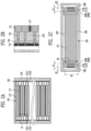
- FIG. 1 is an exploded view of a battery module 200.
- the battery module 200 may include a plurality of battery cells 110 and a busbar assembly 150 electrically connected to the plurality of battery cells 110.
- the busbar assembly 150 may be electrically connected to the outside to store (or charge) electric energy in the plurality of battery cells 110, or supply the electric energy stored in the plurality of battery cells 110 to the outside (or discharge).
- the battery module 200 may further include a case 210 defining a cell accommodating space 280 for accommodating the cell assembly 100.
- the case 210 is intended to protect the cell assembly 100 from the outside.
- the case 210 may include a module body 219 accommodating the cell assembly 100 and a module cover 211 coupled to the module body 219 to define the cell accommodating space 280.
- the module body 219 may be provided in a channel shape or a U-shape in which an upper portion of the cell accommodating space 280 is opened. Therefore, among the side faces of the module body 219, both side faces 2197, 2198 facing each other may also be opened. For example, referring to FIG. 1 , among the side faces of the module body 219, both side faces extending along the X-direction may be open.
- the height direction of a case 210 was set to the +Z direction.
- the +Z direction is a direction assuming that a module cover 211 is at an upper portion a module body 219.
- the -Z direction is a direction assuming that the case 210 is turned over and the module cover 211 is positioned at a lower portion of the module body 219.
- the X-direction is one direction among directions perpendicular to the height direction of the case 210, and when the case 210 has a hexahedral shape, among four side faces forming side faces of the case, two side faces facing each other will extend along the X-direction, and the other two facing side face 2191, 2192 of among the four side faces will extend along the Y-direction.
- a direction parallel to a long edge of the case was set as the Y-direction
- a direction parallel to a short edge of the case was set as the X-direction.
- the cell assembly 100 may further include a buffering member 117 provided between at least a part of the plurality of battery cells 110. Therefore, the cell assembly 100 may include one or more of the buffer members 117.
- the buffering member 117 may be positioned between the battery cells 110, or after the plurality of battery cells 110 are grouped into a preset number, it may be positioned between the grouped battery cells.
- the buffer member 117 is intended to reduce the pressure exerted on other battery cells 110 when the battery cell 110 is swelling. Therefore, the cell assembly 100 may include one or more buffering members 117.
- the plurality of battery cells 110 and the buffering member 117 may be provided at preset positions and stacked. For example, referring to FIG. 1 , an example is shown in which long edges of the plurality of battery cells 110 are arranged side by side in the X-direction. Therefore, the plurality of battery cells 110 and the buffering member 117 will be positioned to overlap in the X-direction.
- the cell assembly 100 may further include end portions 180 at both ends of the cell assembly 100, that is, when the plurality of battery cells 110 are stacked, on exposed faces of the battery cells 110 positioned at the first and last ends.
- the end portion 180 is intended to prevent both side faces of the cell assembly 100 from being exposed to the outside.
- the battery module 200 may further include an insulating cover 170 coupled to both side faces among the side faces the cell assembly except for the side faces where the end portion 180 is positioned. That is, the end portion 180 and the insulating cover 170 may be connected perpendicularly to each other.
- the insulating cover 170 will extend side by side to the busbar assembly 150, and both ends of the insulating cover 170 will be connected to the end portion 180.
- each of the plurality of battery cells 110 may include a rectangular parallelepiped-shaped cell body portion 115 (see FIG. 2C ) that produces or stores electrical energy; and a tab portion 119 (see FIG. 2C ) protruding from the cell body portion 115 along the X-direction (first direction).
- the tab portion 119 may include: a first tab 119a (see FIG. 2C ) and a second tab 119b (see FIG. 2C ) protruding from both side faces of the cell body portion 115 in a direction away from the cell body portion 115. This is an example, and both of the tab portions 119 may be provided on a single side face.
- the cell assembly 100 may include a busbar assembly 150 into which the first tab 119a and the second tab 119b are each inserted and electrically connected.
- the busbar assembly 150 may include: a first busbar 1511 (see FIG. 2A ) electrically connected to the first tab 119a and a first busbar frame 1551 supporting the first busbar 1511 (see FIG. 2A ); and a second busbar 1512 (see FIG. 2A ) electrically connected to the second tab 119b and a second busbar frame 1552 supporting the second busbar 1512.
- first busbar 1511 and the second busbar 1512 which are electrically connected to the first tab 119a and the second tab 119b, respectively, will also be positioned on the side faces on which the first tab 119a and the second tab 119b are disposed.
- first busbar frame 1551 and the second busbar frame 1552 may also be positioned on the side face on which the first tab 119a and the second tab 119b are positioned.
- the busbar assembly 150 may further include a frame connecting portion 155 connecting the first busbar frame 1551 and the second busbar frame 1552 to each other and supporting the same.
- the cell assembly 100 may further include a wire (not shown) provided on the frame connecting portion 155 to electrically connect the busbar assembly 150 to the outside.
- end portion 180 may be provided with a first end plate 181 and a second end plate 182 coupled to both side faces of the cell assembly, among the side faces of the cell assembly, which are provided side by side in a direction from the first tab 119a toward the second tab 119b.
- the plurality of battery cells 110 and the buffering member 117 will be positioned between the first end plate 181 and the second end plate 182.
- the insulating cover 170 When the insulating cover 170 is coupled to the first end plate 181 and the second end plate 182, it may further include: a first insulating cover 171 provided outside the first busbar 1551 and the first busbar frame 1551; and a second insulating cover 172 provided outside the second busbar 1512 and the second busbar frame 1552.
- the first end plate 181, the second end plate 182, the first insulating cover 171, and the second insulating cover 172 will have a form including the one or more battery cells 110 therein.
- the case 210 may further include: a base panel forming a bottom face of the cell accommodating space 280, that is, a lower face of the module body 219; and a first side panel 2191 and a second side panel 2192 bent at both edges provided in parallel with the Y-direction, among the edges of the base panel 2194, to extend toward the module cover 211.
- the module body 219 may be in the form of a U-shaped channel in which both faces along the X-direction are open and the upper face is open.
- the battery module 200 may further include a heat dissipating portion 295 provided between the module body 219 and the cell assembly 100 to be in contact with the cell assembly 100.
- the heat dissipating portion 295 is intended to radiate heat that is generated from the cell assembly 100 to the outside.
- the heat dissipating portion 295 may be provided in the form of a heat dissipating pad or thermal adhesive with excellent thermal conductivity.
- FIG. 2A shows an example of a cross-section of the battery module. That is, FIG. 2A is an example of a cross-section of the battery module 200 viewed from above.
- the cell assembly 100 may be in the form of a stack of a plurality of battery cells 110 and a shock absorbing member 117. Each of the plurality of battery cells 110 may include the first tab 119a (see FIG. 2C ) and the second tab 119b (see FIG. 2C ) provided at both end areas of the battery cell 110.
- the cell assembly 100 may include a busbar assembly 150 into which the first tab 119a and the second tab 119b are each inserted and electrically connected.
- the busbar assembly 150 may include: a first busbar 1511 electrically connected to the first tab 119a and a first busbar frame 1551 supporting the first busbar 1511; and a second busbar 1551 electrically connected to the second tab 119b and a second busbar frame 1552 supporting the second busbar 1512.
- FIG. 2B shows an enlarged diagram of S1 part, which is a part of the cross-section of FIG. 2A.
- FIG. 2C shows an example of a cross-section of the battery module viewed from another direction.
- the cell accommodating space 280 in which the cell assembly 100 is accommodated may be subdivided into several spaces.
- the subdivided space may include: an installation space 281 in which the cell assembly 100 is positioned; a first space 285 provided outside the first busbar 1511 and the first busbar frame 1551; a second space 286 provided outside the second busbar 1512 and the second busbar frame 1552; and a cover space 287 provided between an upper portion of the cell assembly 100 and the module cover 211 (see FIG. 1 ).
- an empty space may also be defined between the plurality of battery cells 110 and the busbar assembly 150.
- an empty space may also be positioned between a side face of the cell body portion 115 where the first tab 119a is positioned and the first busbar frame 1551, and between a side face of the cell body portion 115 where the second tab 119b is positioned and a second busbar frame 1552. This is because at least a portion of the first tab 119a and the second tab 119b are inserted into the first bus ar 1511 and the second busbar 1512 and are electrically connected, so that an empty space may be formed therebetween.
- the battery module 200 may further include a filler space 288 defined between the plurality of battery cells 110 and the busbar assembly 150.
- the battery module 200 include a first filler space 2881 and a second filler space 2882 between one side face of each cell body portion 115 of any one of the plurality of battery cells 110 and the first busbar frame 1551 and between the other side face of each cell body portion 115 of any one of the plurality of battery cells 110 and the second busbar frame 1552, respectively.
- One side face of the cell body portion 115 may be a side face on which the first tab 119a is positioned, and the other side face of the cell body portion 115 may be a side face on which the second tab 119b is positioned.
- both the first filler space 2881 and the second filler space 2882 may be communicated.
- the battery module 200 may include a filler portion 270 that is positioned in the filler space 288 and made of a material having heat-resistance and/or flame-retardance.
- the materials of the filler portions 270 positioned in the first filler space 2881 and the second filler space 2882 may be different from each other.
- the length of the first filler space 2881 and the length of the filler space 288 along the direction from the first tab 119a to the second tab 119b, that is, the X-direction may be different from each other. This is intended to use a filler portion 270 with a desired function at a desired position for more efficient space utilization.
- the battery module 200 may include a heat dissipating portion 295 at a lower portion of the cell assembly 100, that is, between the cell assembly 100 and the base panel 2194 (see FIG. 1 ).
- the heat dissipating portion 295 is intended to transfer heat generated from the cell assembly 100 to the outside.
- the heat dissipating portion 295 may be positioned below the first filler space 2881 and the second filler space 2882. This is because a part that requires heat transfer from the battery cell 100 to the outside is the cell body portion 115.
- the filler portion 270 when the filler portion 270 is made of a liquid material, the filler portion 270 may also enter between the plurality of stacked battery cells 110 and the buffering member 117. This is because, even when the plurality of battery cells 110 and the buffering member 117 are in contact with each other without a gap, the filler portion 270 may enter into a gap that is not visible to the naked eye due to a capillary phenomenon.
- the filler portion 270 when the filler portion 270 is in a liquid form, considering the viscosity of the filler portion 270, the amount entering the gap will not be very large. Likewise, even when the filler portion 270 is in a liquid state, the heat dissipating portion 295 and the filler portion 270 may be separated so that they may be distinguished rather than mixed. This is because the density and viscosity of the filler portion 270 and the heat dissipating portion 295 are different from each other.
- the length B1 of the first space 285 may be different from the length L1 of the first filler space 2881.
- the length B2 of the second space 286 may be different from the length L2 of the second filler space 2882.
- the length B1 of the first space 285 may the same as the length L1 of the first filler space 2881.
- the length L1 of the first filler space 2881 may be different from the length L2 of the second filler space 2882.
- the height H2 of the battery cell 110 may be different from the height of the filler portion 270.
- the height H2 of the battery cell 110 may be smaller than the height of the filler portion 270. This is due to the height of the heat dissipating portion 295.
- the maximum height H1 of the filler portion 270 may be different from the maximum height of the plurality of battery cells 110 positioned in the cell accommodating space 280.
- the maximum height H1 of the filler portion 270 will be equal to or greater than the maximum height of the plurality of battery cells 110 positioned in the cell accommodating space 280.
- functions of the filler portion 270 described in the present disclosure may be performed.
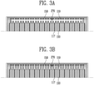
- FIGS. 3A and 3B show another example of a filler portion 270.
- the filler portion 270 may include a heat-resistant and/or flame-retardant material. Therefore, as long as the material is a heat-resistant and/or flame-retardant material, the phase of the filler portion 270 may be liquid or solid.
- the filler portion 270 may be a composite material made of several materials rather than a single material. Some materials may be provided to satisfy heat-resistance, and other materials may be provided for flame-retardancy. In addition, rather than being mixed and provided as one integrated form, the various materials may be separated and have a stacked form.
- a high-temperature gas or smoke trapped inside may be discharged in a direction where the tab portion 119 is positioned. This may be referred to as thermal runaway. This may cause a high-temperature gas or smoke to be discharged in an unintended direction, thereby accelerating heat propagation to other adjacent battery cells 110.
- the filler portion 270 may prevent a joint portion of the tab portion 119 and the cell body portion 115 (see FIG. 2C ) from gaping, thereby preventing a high-temperature gas or smoke from being discharged in a direction where the tab portion 119 is positioned.
- the filler portion 270 may mitigate discharge of the high-temperature gas or smoke in a direction where the tab portion 119 is positioned through a joint portion of the tab portion 119 and the cell body portion 115 (see FIG. 2C ).
- the filler portion 270 may be provided in a solid form. That is, the filler portion 270 may be molded into a desired shape in advance before being assembled into the cell assembly 100.
- the buffering member 117 is each provided between battery cells 110 grouped in pairs. This is just one example, and the buffering member 117 does not need to be disposed between the battery cells in an equally set interval.
- FIG. 3B shows an example in which the filler portion 270 is provided in a liquid state and filled in the filler space 288 (see FIG. 2C ). Even when it is in a liquid state, considering the viscosity, which will be described later, the filler portion 270 may remain in the filler space 288 even after time passes.
- the filler portion 270 may include a heat-resistant and/or flame-retardant material.
- the filler portion 270 may be formed of a solid, liquid, or post-cured liquid type material.
- the filler portion 270 may include a silicone resin, an epoxy resin, or a urethane resin.
- the filler portion 270 may have a 5% weight loss temperature of 400 °C or higher in a thermogravimetric analysis (TGA), or an 800 °C remaining weight of 70% by weight or higher. Due to these characteristics, the stability of the battery module at high temperatures can be further improved. In the thermogravimetric analysis (TGA), measurement may be performed within a range of 25 °C to 800 °C at a temperature increase rate of 20 °C/min in a nitrogen (N 2 ) environment of 60 cm 3 /min.
- TGA thermogravimetric analysis
- the filler portion 270 may also perform a function of securing the plurality of battery cells 110.
- a solid state filler portion 270 or a filler portion 270 which is injected in a liquid state and then cured, may prevent the tab portion 119 from being deformed by an external shock or the like, after the tab portion 119 is inserted into the busbar assembly 150.
- a liquid state filler portion 270 will also be able to prevent deformation of the tab portion 119 to some extent due to the viscosity thereof.
- a filler portion 270 which is injected in a liquid state and then cured, specifically includes an acrylic resin, an epoxy resin, a urethane resin, an olefin resin, an ethylene vinyl acetate (EVA) resin, a silicone resin, or the like.
- an acrylic resin an epoxy resin, a urethane resin, an olefin resin, an ethylene vinyl acetate (EVA) resin, a silicone resin, or the like.
- a liquid state filler portion 270 or a cured type filler portion 270 may further include a viscosity modifying agent, for example, a thixotropic agent, a diluent, a dispersant, a face treatment agent, or a coupling agent, in order to control the viscosity in a liquid state.
- a viscosity modifying agent for example, a thixotropic agent, a diluent, a dispersant, a face treatment agent, or a coupling agent, in order to control the viscosity in a liquid state.
- the thixotropic agent may adjust the viscosity of a resin composition according to the shear force to ensure that the manufacturing process of the battery module is carried out effectively.
- Examples of applicable thixotropic agents include fumed silica or the like.
- the viscosity of the filler portion 270 may be 100 cPs (centi-poise) or more and 600 (cPs) or less based on 25 °C.
- a diluent or a dispersant is usually used to lower the viscosity of a resin composition, and various types known in the industry may be used without limitation as long as they can exhibit the abovementioned effect.
- a face treatment agent is for face treatment of a filler introduced into the filler portion 270, and various types known in the industry can be used without limitation as long as they can exhibit the abovementioned effect.
- the filler portion 270 may include a flame-retardant material.
- a flame-retardant material refers to a material that is difficult to melt at high temperatures.
- various known flame-retardants may be applied as a flame-retardant material without any particular limitation, and for example, flame-retardants in the form of a solid filler or liquid flame-retardants may be applied.
- Flame-retardants include, for example, organic flame-retardants such as melamine cyanurate and inorganic flame-retardants such as magnesium hydroxide, but are not limited thereto.
- a flame-retardant material may mean a polymer material that has a V-0 class in the 94V test (vertical burning test) of Underwriter's Laboratory (UL), which is a flame-retardant standard for polymer materials.
- V-0 class in the 94V test vertical burning test
- UL Underwriter's Laboratory
- the filler portion 270 may further include a heat-resistant or flame-retardant material.
- the heat-resistant or flame-retardant material include phosphorus-based, halogen-based, and inorganic flame-retardants, and a phosphorus-based flame-retardant material may preferably include a phosphate compound, a phosphonate compound, a phosphinate compound, a phosphine oxide compound, a phosphazene compound, and a metal salt thereof. These may be used individually or in combination of two or more types.
- a temperature range in which the filler portion 270 has the intended heat resistance and flame-retardancy may be -60 °C or higher and 120 °C or lower.
- the solid or cured filler portion 270 may preferably have appropriate hardness. That is, this is to ensure the impact resistance and vibration resistance of the filler portion 270 without high brittleness of the filler portion 270 so that the filler portion 270 has improved durability.
- the hardness of the filler portion 270 may be 35 or more and 45 or less.
- the filler portion 270 may include an electrically insulating material.
- the dielectric strength of the pillar portion 270 may preferably be at least 3.0 (kV/mm).
- the thermal conductivity of the filler portion 270 may preferably be 0.05 (W/m-K) or less. Considering that the filler portion 270 is a heat-resistant material, the thermal conductivity of the filler portion 270 will be smaller than that of the heat dissipating portion 295.
- the foam density of the foam material may be 0.1 (g/cm 3 ) or more and 0.2 (g/cm 3 ) or less upon free rise.
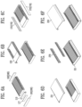
- FIG. 4A shows an example of a filler portion 270 molded into a preset shape
- FIG. 4B shows an enlarged diagram of a part of the filler portion 270.
- the filler portion 270 may be in a solid form. That is, the filler portion 270 may be molded into a preset shape before being coupled to the cell assembly 100. Preferably, the filler portion 270 may be provided in the form of a foam.
- the filler portion 270 may be coupled after inverting the battery module 200 being assembled.
- the module cover 211 may be coupled before the module body 219 (see FIG. 1 ). Therefore, to insert the filler portion 270 between the plurality of battery cells 110 and the busbar assembly 150 in a state in which the module cover 211 is coupled, the battery module 200 being assembled will be inverted, and then the filler portion 270 will be inserted.
- the filler portion 270 may include: a first filler portion 2701 accommodated in the first filler space 2881 (see FIG. 2C ); and a second filler portion 2702 accommodated in the second filler space 2882 (see FIG. 2C ).
- FIG. 4B is an enlarged view of S2 region in FIG. 4A .
- a direction toward the cell assembly 100 is determined as front (F)
- a direction toward the plurality of battery cells 110 is indicated as rear (R).
- the Z-direction is indicated downward, which is intended to emphasize that the module cover 211 is below the cell assembly 100, as the battery module 200 being assembled is inverted.
- the filler portion 270 may be provided in an individual form to be inserted between tab portions 119 of each of any one battery cell 110 (see FIG. 1 ) and another adjacent battery cell 110.
- the assembly time may be long, and a lot of empty space may remain between the plurality of battery cells 110 and the busbar assembly 150.
- the filler portion 270 may further include: a body portion 2701b inserted between tab portions 119 of each of the plurality of battery cells 110; and a connecting portion 2701c positioned at one end positioned farther from the module cover 211, among both ends of the body portion 2701b, and connecting the body portion 2701b.
- the plurality of body portions 2701b may be spaced in a constant interval and further include inserting portions 2701a in the form of a hole or a groove between the plurality of body portions.
- the positions of the insertion portions 2701a will be arranged to correspond to the positions of the tab portions 119.
- the connecting portion 2701c is caught on the tab portion 119 and thus it may play the role of a stopper upon the installation of the filler portion 270.
- connecting portion 2701c may be provided in a form extending toward the rear where the busbar assembly 150 is positioned. This is intended to fill a space between the busbar assembly 150 and the base panel 2194 (see FIG. 1 ).
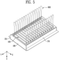
- FIG. 5 shows an example of a method of injecting a filler portion 270 injected in a liquid form. Referring to FIG. 5 , the Z-direction is indicated downward, which is intended to emphasize that the module cover 211 is below the cell assembly 100, as the battery module 200 being assembled is inverted.
- the battery module 200 being assembled shown in FIG. 5 , has an end portion 180 and an insulating cover 170 coupled, and after the module cover 211 is coupled, the battery module 200 being assembled is in an inverted form. Therefore, it can be seen that the end portion 180 and the insulating cover 170 play the role of side faces, and the module cover 211 plays the role of a bottom face so that a type container that can contain a liquid is formed by the module cover 211, the end portion 180, and the insulating cover 170.
- the inverted battery module 200 may accommodate a liquid filler portion 270 in a filler space 288.
- FIG. 5 shows an example of an injecting portion 900 injecting a filler portion 270 of a liquid form into a first filler space 2881 and a second filler space 2882.
- the injecting portion 900 may include dispensers each disposed between a tab portion 119 (see FIG. 2C ) and another tab portion 119 of a plurality of battery cells 110. Through this, the injection portion 900 will be able to inject a liquid filler portion 270 into all filler spaces 288 simultaneously.
- FIG. 5 does not show all of the injection portions 900, but only shows them sparsely in a few places.
- the injection portions 900 may be disposed one by one in the first filler spaces 2881 (see FIG. 2C ) and the second filler spaces 2882 ( FIG. 2C ) to sequentially fill each filler space 288 with a liquid filler portion 270.
- the time required to fill the filler spaces 288 with a filler portion 270 it may be preferable to fill the filler spaces 288 simultaneously.
- FIGS. 6A and 6B briefly show an example of a method of assembling the battery module 200.
- FIG. 7 shows a flowchart of an example of the method of assembling the battery module 200.
- the assembling method of the present disclosure includes a step S100 of assembling a cell assembly 100 including the plurality of battery cells 110 and a busbar assembly 150 electrically connected to the plurality of battery cells 110.
- the step S100 of assembling a cell assembly 100 may include a stacking step S110 of stacking the plurality of battery cells 110 and a buffering member 117 positioned between the plurality of battery cells 110.
- the stacking step S110 may include stacking each of a first end plate 181 and a second end plate 182 at the first and last in a perpendicular direction of the busbar assembly 150 or in a direction in which the plurality of battery cells 110 are stacked.
- the step S100 of assembling a cell assembly 100 may further include a step S150 of connecting a busbar assembly 150 to the stacked battery cells 110, after the stacking step S110.
- the busbar assembly 150 may also include: a first busbar 1511 and a first busbar frame 1551 coupled to one face to which the first tab 119a (see FIG. 2C ) is coupled; and a second busbar 1512 and a second busbar frame 1552 coupled to one face to which the second tab 119b (see FIG. 2C ) is coupled.
- the first tab 119a may be electrically connected to the first busbar 1511
- the second tab 119b may be electrically connected to the second busbar 1512.
- the assembling method of the present disclosure may further include a step S210 of coupling an insulating cover 170 provided in a parallel direction to the busbar assembly 150 to the cell assembly 100.
- a first insulating cover 171 among the insulating covers 170 may be coupled in a direction in which the first busbar 1511 is positioned, and a second insulating cover 172 among the insulating covers 170 may be coupled in a direction in which the second busbar 1512 is positioned.
- the first insulating cover 171 and the second insulating cover 172 will be coupled to the first end plate 181 and the second end plate 182.
- the assembling method of the present disclosure may include a step S250 of coupling the module cover 211 to the cell assembly 100.
- the reason for assembling the module cover 211 before the module body 219 is to protect the busbar assembly 150 during the assembly process.
- the assembling method of the present disclosure may go through a first inverting step S300 of inverting the battery module 200 being assembled.
- the reason for inverting the battery module 200 being assembled is to locate the filler portion 270 into the first filler space 2881 (see FIG. 2C ) and the second filler space 2882 (see FIG. 2C ). Since it is difficult to insert the filler portion 270 from above due to the already assembled module cover 211, the battery module 200 being assembled is inverted to locate the filler portion 270.
- the assembling method of the present disclosure may include a step S400 of forming the filler portion 270 after the first inverting step S300.
- the filler portion 270 When the filler portion 270 has a preset shape in a solid state, like an example shown in FIG. 6E , the filler portion 270 may be caused to approach the module cover 211 from an opposite direction of the module cover 211 to locate the filler portion 270 to the filler space 288.
- the filler portion 270 When the filler portion 270 is in a liquid state or a type that is injected as a liquid and then cured, like an example shown in FIG. 5 , the filler portion 270 may be formed by filling the same into the filler space 288 using the injection portion 900.
- the assembling method of the present disclosure may further include a step S550 of coupling the module body 219 to the module cover 211.
- the module body 219 may be caused to approach the module cover 211 in a direction from top to bottom for coupling S550 to the module cover 211.
- the battery module 200 may further include a heat dissipating portion 295 on a base panel 2194 (see FIG. 1 ), which is a lower face of the module body 219, or on a bottom face of the cell accommodating space 280.
- the assembling method of the present disclosure may include a step of forming the heat dissipating portion 295 on the base panel 2194 by injecting or coating the heat dissipating portion before coupling S550 the module body 219 to the module cover 211.
- the assembling method of the present disclosure may include a second inverting step S600 of re-inverting the battery module 200 so that the module cover 211 may be positioned on top. This is for inspecting S700 of the battery module 200 in a normal state.
Landscapes
- Chemical & Material Sciences (AREA)
- Chemical Kinetics & Catalysis (AREA)
- Electrochemistry (AREA)
- General Chemical & Material Sciences (AREA)
- Engineering & Computer Science (AREA)
- Manufacturing & Machinery (AREA)
- Battery Mounting, Suspending (AREA)
- Secondary Cells (AREA)
Abstract
The present disclosure relates to a battery module and an assembling method of the same including: a cell assembly including a plurality of battery cells and a busbar assembly for electrically connecting the plurality of battery cells; a case forming a cell accommodating space for accommodating the cell assembly therein; and a filler portion provided between the plurality of battery cells and the busbar assembly inside the case and including a flame-retardant material.
Description
- The present disclosure relates to a battery module, which is a collection of secondary batteries or battery cells, and a method of assembling the battery module. More specifically, it relates to a battery module that delays thermal propagation of battery cells and a method of assembling the battery module.
- Recently, due to fire or explosion accidents occurring during the use of lithium secondary batteries, social concerns about the safety of battery use are increasing. Based on these social concerns, one of the recent major developmental tasks of lithium secondary batteries is to eliminate instabilities such as fire and explosion caused by thermal runaway of battery cells.
- In particular, a typical battery module only considers a gap between a tab of any one battery cell and a tab of another adjacent battery cell, but does not consider the height of battery cells. In this case, there is a problem that it is impossible to prevent a gas generated from a battery cell in which thermal runaway has occurred from escaping through an empty space in a tab direction.
- First, a technical problem that one aspect of the present disclosure is intended to solve is to prevent or mitigate escape of a high-temperature gas generated from a battery cell in which thermal runaway has occurred, among one or more battery cells provided inside a battery module, in a tab direction of the battery cell.
- Second, a technical problem that another aspect of the present disclosure is intended to solve is to vente a high-temperature gas generated from a battery cell in which thermal runaway has occurred, in an intended path.
- Third, a technical problem that still another aspect of the present disclosure is intended to solve is to add a process of positioning a filler portion between tabs of a busbar assembly and a battery to an existing battery module assembly process.
- Meanwhile, a battery module according to the present disclosure can be widely applied in the field of green technology, such as electric vehicles, battery charging stations, energy storage systems (ESS), solar power generation (photovoltaics), and wind power generation using batteries. In addition, a battery module according to the present disclosure can be used in eco-friendly mobility including electric vehicles and hybrid vehicles to prevent climate change by suppressing air pollution and greenhouse gas emissions.
- To solve the above-described problem, in a battery module according to the present disclosure, a filler made of a flame-retardant and heat-resistant material is positioned in an empty space of a battery module, specifically between a battery cell and a busbar assembly.
- More specifically, a battery module according to the present disclosure may include: a cell assembly including a plurality of battery cells and a busbar assembly for electrically connecting the plurality of battery cells; a case defining a cell accommodating space for accommodating the cell assembly therein; and a filler portion provided between the plurality of battery cells and the busbar assembly inside the case and including a flame-retardant material.
- The plurality of battery cells may each include: a cell body portion generating or storing electrical energy; and a tab portion protruding from the cell body portion toward the busbar assembly and electrically connecting the cell body portion and the busbar assembly, wherein the filler portion may be positioned in a filler space defined between one side face of the cell body portion from which the tab portion protrudes and the busbar assembly.
- The tab portion may include a first tab and a second tab protruding from the cell body portion toward the busbar assembly any one direction among directions perpendicular to the height direction of the case, wherein the busbar assembly may include: a first busbar electrically connected to the first tab and a first busbar frame supporting the first busbar; and a second busbar electrically connected to the second tab and a second busbar frame supporting the second busbar, and wherein the filler space may include: a first filler space provided between a part in which the first tab is positioned and the first busbar frame; and a second filler space provided between a part in which the second tab is positioned and the second busbar frame.
- Along a direction from the first filler space to the second filler space, the length of the first filler space may be different from the length of the second filler space.
- The battery module may further include: a heat dissipating portion positioned between the cell assembly and a bottom surface of the cell accommodating space to dissipate heat generated from the plurality of battery cells to the outside through the case, wherein the heat dissipating portion may be positioned between the first filler space and the second filler space.
- The filler portion may be formed of a polymer material that is cured after being injected into the filler space.
- The filler portion may be filled in the filler space in a liquid form.
- The filler portion may include: a body portion including an insertion groove extending along the height direction of the case to insert the tab portion and electrically connect the tab portion to the busbar assembly; and a connecting portion extending from one side of the body portion in a direction toward the busbar assembly.
- The battery module may further include: a first insulation cover positioned in a direction from the outside of the first busbar frame to one side face of the case which is positioned closer to the first busbar frame, among both side faces facing the first busbar frame, to insulate between the first busbar and the case; and a second insulation cover positioned in a direction from the second busbar frame to the other face of the case to insulate between the second busbar and the case.
- The cell assembly may further include a first end plate and a second end plate respectively connected to the first insulation cover and the second insulation cover to surround the plurality of battery cells.
- The battery module may further include a module cover coupled to the first insulation cover, the second insulation cover, the first end plate, and the second end plate.
- Based on a bottom face of the cell accommodating space, the maximum height of the filler portion may be more than half of the maximum height of the plurality of battery cells positioned in the cell accommodating space.
- Meanwhile, the case may include: a module body including an opening portion in an upper portion thereof, extending along a first direction, which is any one direction among directions perpendicular to the height direction of the case, and formed in a U-shape of which both side faces perpendicular to the first direction are open; and a module cover coupled to the module body to close the opening portion.
- The battery module may further include a heat dissipating portion positioned between the cell assembly and a bottom face of the cell accommodating space to dissipate heat generated from the plurality of battery cells to the outside through the case.
- The filler portion may further include a heat-resistant material.
- Meanwhile, a method of assembling a battery module according to the present disclosure, which is a method of assembling a battery module including a cell assembly including a plurality of battery cells and a busbar assembly for electrically connecting the plurality of battery cells; a case forming a cell accommodating space for accommodating the cell assembly therein, may include: a step of coupling a module cover coupled with one face of the case with the cell assembly; a step of inverting the cell assembly coupled with the module cover; and a step of forming a filler portion between the busbar assembly and the one or more battery cell.
- In the step of forming a filler portion, the filler portion may be moved toward the inverted cell assembly to face an inner side of the bus bar assembly.
- In the step of forming a filler portion, the filler portion in a liquid state may be injected to be filled between the plurality of battery cells and the busbar assembly.
- The method of assembling a battery module may further include a step of coupling a module body defining the cell accommodating space together with the module cover with the module cover, after forming of the filler portion.
- In addition, the method of assembling the battery module may further include a step of re-inverting the module body after coupling the module body to the module cover.
- First, according to one embodiment of the present disclosure, escape of a gas generated from a battery cell in which thermal runaway has occurred, among a plurality of battery cells provided inside a battery module, in a tab direction of the battery cell may be prevented or mitigated. Through this, the stability of the battery module may be improved.
- Second, according to another embodiment of the present disclosure, a high-temperature gas generated from a battery cell in which thermal runaway has occurred may be vented in an intended path.
- Third, according to still another embodiment of the present disclosure, a process of positioning a filler portion may be added to an existing battery module assembly process without making a significant change.
-
-
FIG. 1 shows an exploded view of a battery module. -
FIG. 2A shows an example of a cross-section of the battery module;FIG. 2B shows an enlarged diagram of a part of the cross-section ofFIG. 2A; and FIG. 2C shows an example of a cross-section of the battery module viewed from another direction. -
FIGS. 3A and 3B show another example of a filler portion. -
FIG. 4A shows an example of a filler portion molded into a preset shape; andFIG. 4B shows an enlarged diagram of a part of the filler portion. -
FIG. 5 shows an example of a method of injecting a filler portion injected in a liquid form. -
FIGS. 6A to 6F briefly show an example of a method of assembling the battery module. -
FIG. 7 shows a flowchart of an example of the method of assembling the battery module. - Hereinafter, preferred embodiments of the present disclosure will be described in detail with reference to the attached drawings. The configuration or control method of the device described below is only for explaining the embodiments of the present disclosure and is not intended to limit the scope of the present disclosure, and the same reference numerals used throughout the specification indicate the same components.
- Specific terms used in the present specification are merely for convenience of explanation and are not used to limit the illustrated embodiments.
- A battery cell described in the present specification refers to a basic unit of a lithium secondary battery, specifically a lithium-ion battery, that can be used by charging and discharging electrical energy. The main components of the battery cell are a cathode, an anode, a separator, and an electrolyte, and the battery cell is manufactured by putting these main components into a case (or pouch). The battery cell may include a tab that is each connected to the cathode and the anode for electrical connection to the outside and protrudes to the outside of the pouch.
- Meanwhile, a battery module described in the present specification refers to a battery assembly in which the battery cells are bundled in one or more numbers and put into a case to protect them from external shock, heat, vibration, or the like. The plurality of battery cells may supply electricity to the outside or receive electricity from the outside through a busbar assembly that is electrically connected.
- In addition, a battery pack refers to a set in which a preset number of battery modules are gathered together and electrically connected to achieve a final desired voltage or power.
-
FIG. 1 is an exploded view of abattery module 200. Referring toFIG. 1 , thebattery module 200 may include a plurality ofbattery cells 110 and abusbar assembly 150 electrically connected to the plurality ofbattery cells 110. In particular, after the plurality ofbattery cells 110 are stacked, they may be electrically connected by thebusbar assembly 150. This is referred to as acell assembly 100. Thebusbar assembly 150 may be electrically connected to the outside to store (or charge) electric energy in the plurality ofbattery cells 110, or supply the electric energy stored in the plurality ofbattery cells 110 to the outside (or discharge). - The
battery module 200 may further include acase 210 defining a cellaccommodating space 280 for accommodating thecell assembly 100. Thecase 210 is intended to protect thecell assembly 100 from the outside. - The
case 210 may include amodule body 219 accommodating thecell assembly 100 and amodule cover 211 coupled to themodule body 219 to define the cellaccommodating space 280. - The
module body 219 may be provided in a channel shape or a U-shape in which an upper portion of the cellaccommodating space 280 is opened. Therefore, among the side faces of themodule body 219, both side faces 2197, 2198 facing each other may also be opened. For example, referring toFIG. 1 , among the side faces of themodule body 219, both side faces extending along the X-direction may be open. - In the present disclosure, the height direction of a
case 210 was set to the +Z direction. The +Z direction is a direction assuming that amodule cover 211 is at an upper portion amodule body 219. On the other hand, the -Z direction is a direction assuming that thecase 210 is turned over and themodule cover 211 is positioned at a lower portion of themodule body 219. - In addition, in the present disclosure, the X-direction is one direction among directions perpendicular to the height direction of the
case 210, and when thecase 210 has a hexahedral shape, among four side faces forming side faces of the case, two side faces facing each other will extend along the X-direction, and the other two facingside face - The
cell assembly 100 may further include abuffering member 117 provided between at least a part of the plurality ofbattery cells 110. Therefore, thecell assembly 100 may include one or more of thebuffer members 117. The bufferingmember 117 may be positioned between thebattery cells 110, or after the plurality ofbattery cells 110 are grouped into a preset number, it may be positioned between the grouped battery cells. Thebuffer member 117 is intended to reduce the pressure exerted onother battery cells 110 when thebattery cell 110 is swelling. Therefore, thecell assembly 100 may include one ormore buffering members 117. - The plurality of
battery cells 110 and thebuffering member 117 may be provided at preset positions and stacked. For example, referring toFIG. 1 , an example is shown in which long edges of the plurality ofbattery cells 110 are arranged side by side in the X-direction. Therefore, the plurality ofbattery cells 110 and thebuffering member 117 will be positioned to overlap in the X-direction. - The
cell assembly 100 may further includeend portions 180 at both ends of thecell assembly 100, that is, when the plurality ofbattery cells 110 are stacked, on exposed faces of thebattery cells 110 positioned at the first and last ends. - The
end portion 180 is intended to prevent both side faces of thecell assembly 100 from being exposed to the outside. - The
battery module 200 may further include an insulatingcover 170 coupled to both side faces among the side faces the cell assembly except for the side faces where theend portion 180 is positioned. That is, theend portion 180 and the insulatingcover 170 may be connected perpendicularly to each other. - The insulating
cover 170 will extend side by side to thebusbar assembly 150, and both ends of the insulatingcover 170 will be connected to theend portion 180. - Meanwhile, each of the plurality of
battery cells 110 may include a rectangular parallelepiped-shaped cell body portion 115 (seeFIG. 2C ) that produces or stores electrical energy; and a tab portion 119 (seeFIG. 2C ) protruding from thecell body portion 115 along the X-direction (first direction). - Specifically, the
tab portion 119 may include: afirst tab 119a (seeFIG. 2C ) and asecond tab 119b (seeFIG. 2C ) protruding from both side faces of thecell body portion 115 in a direction away from thecell body portion 115. This is an example, and both of thetab portions 119 may be provided on a single side face. - Referring to
FIGS. 1 and2C , thecell assembly 100 may include abusbar assembly 150 into which thefirst tab 119a and thesecond tab 119b are each inserted and electrically connected. Specifically, thebusbar assembly 150 may include: a first busbar 1511 (seeFIG. 2A ) electrically connected to thefirst tab 119a and afirst busbar frame 1551 supporting the first busbar 1511 (seeFIG. 2A ); and a second busbar 1512 (seeFIG. 2A ) electrically connected to thesecond tab 119b and asecond busbar frame 1552 supporting thesecond busbar 1512. - In other words, since the
first tab 119a and thesecond tab 119b are disposed on both sides of thecell body portion 115, corresponding thereto, thefirst busbar 1511 and thesecond busbar 1512, which are electrically connected to thefirst tab 119a and thesecond tab 119b, respectively, will also be positioned on the side faces on which thefirst tab 119a and thesecond tab 119b are disposed. Likewise, thefirst busbar frame 1551 and thesecond busbar frame 1552 may also be positioned on the side face on which thefirst tab 119a and thesecond tab 119b are positioned. - The
busbar assembly 150 may further include aframe connecting portion 155 connecting thefirst busbar frame 1551 and thesecond busbar frame 1552 to each other and supporting the same. Thecell assembly 100 may further include a wire (not shown) provided on theframe connecting portion 155 to electrically connect thebusbar assembly 150 to the outside. - In addition, the
end portion 180 may be provided with afirst end plate 181 and asecond end plate 182 coupled to both side faces of the cell assembly, among the side faces of the cell assembly, which are provided side by side in a direction from thefirst tab 119a toward thesecond tab 119b. - Therefore, the plurality of
battery cells 110 and thebuffering member 117 will be positioned between thefirst end plate 181 and thesecond end plate 182. - When the insulating
cover 170 is coupled to thefirst end plate 181 and thesecond end plate 182, it may further include: a first insulatingcover 171 provided outside thefirst busbar 1551 and thefirst busbar frame 1551; and a secondinsulating cover 172 provided outside thesecond busbar 1512 and thesecond busbar frame 1552. - The
first end plate 181, thesecond end plate 182, the first insulatingcover 171, and the second insulatingcover 172 will have a form including the one ormore battery cells 110 therein. - Meanwhile, the
case 210 may further include: a base panel forming a bottom face of the cellaccommodating space 280, that is, a lower face of themodule body 219; and afirst side panel 2191 and asecond side panel 2192 bent at both edges provided in parallel with the Y-direction, among the edges of thebase panel 2194, to extend toward themodule cover 211. Through this, themodule body 219 may be in the form of a U-shaped channel in which both faces along the X-direction are open and the upper face is open. - The
battery module 200 may further include aheat dissipating portion 295 provided between themodule body 219 and thecell assembly 100 to be in contact with thecell assembly 100. Theheat dissipating portion 295 is intended to radiate heat that is generated from thecell assembly 100 to the outside. For example, theheat dissipating portion 295 may be provided in the form of a heat dissipating pad or thermal adhesive with excellent thermal conductivity. -
FIG. 2A shows an example of a cross-section of the battery module. That is,FIG. 2A is an example of a cross-section of thebattery module 200 viewed from above. As described above, thecell assembly 100 may be in the form of a stack of a plurality ofbattery cells 110 and ashock absorbing member 117. Each of the plurality ofbattery cells 110 may include thefirst tab 119a (seeFIG. 2C ) and thesecond tab 119b (seeFIG. 2C ) provided at both end areas of thebattery cell 110. In addition, thecell assembly 100 may include abusbar assembly 150 into which thefirst tab 119a and thesecond tab 119b are each inserted and electrically connected. Specifically, thebusbar assembly 150 may include: afirst busbar 1511 electrically connected to thefirst tab 119a and afirst busbar frame 1551 supporting thefirst busbar 1511; and asecond busbar 1551 electrically connected to thesecond tab 119b and asecond busbar frame 1552 supporting thesecond busbar 1512. -
FIG. 2B shows an enlarged diagram of S1 part, which is a part of the cross-section ofFIG. 2A. FIG. 2C shows an example of a cross-section of the battery module viewed from another direction. - Referring to
FIGS. 2B and 2C , the cellaccommodating space 280 in which thecell assembly 100 is accommodated may be subdivided into several spaces. For example, examples of the subdivided space may include: aninstallation space 281 in which thecell assembly 100 is positioned; afirst space 285 provided outside thefirst busbar 1511 and thefirst busbar frame 1551; asecond space 286 provided outside thesecond busbar 1512 and thesecond busbar frame 1552; and acover space 287 provided between an upper portion of thecell assembly 100 and the module cover 211 (seeFIG. 1 ). - Since the first insulating cover 171 (see
FIG. 1 ) and the second insulating cover 172 (seeFIG. 1 ) may be positioned in thefirst space 285 and thesecond space 286, respectively, the first space and the second space may refer to a space excluding the first insulatingcover 171 and the second insulatingcover 172. - In addition to the subdivided spaces, an empty space may also be defined between the plurality of
battery cells 110 and thebusbar assembly 150. Specifically, an empty space may also be positioned between a side face of thecell body portion 115 where thefirst tab 119a is positioned and thefirst busbar frame 1551, and between a side face of thecell body portion 115 where thesecond tab 119b is positioned and asecond busbar frame 1552. This is because at least a portion of thefirst tab 119a and thesecond tab 119b are inserted into thefirst bus ar 1511 and thesecond busbar 1512 and are electrically connected, so that an empty space may be formed therebetween. - In other words, the
battery module 200 may further include afiller space 288 defined between the plurality ofbattery cells 110 and thebusbar assembly 150. - More specifically, the
battery module 200 include afirst filler space 2881 and asecond filler space 2882 between one side face of eachcell body portion 115 of any one of the plurality ofbattery cells 110 and thefirst busbar frame 1551 and between the other side face of eachcell body portion 115 of any one of the plurality ofbattery cells 110 and thesecond busbar frame 1552, respectively. - One side face of the
cell body portion 115 may be a side face on which thefirst tab 119a is positioned, and the other side face of thecell body portion 115 may be a side face on which thesecond tab 119b is positioned. - When the
cell assembly 100 is installed in thecase 210, since the length of thefirst tab 119a and thesecond tab 119b along the height direction of thecase 210 is shorter than the length of thebattery cell 110, both thefirst filler space 2881 and thesecond filler space 2882 may be communicated. - The
battery module 200 may include afiller portion 270 that is positioned in thefiller space 288 and made of a material having heat-resistance and/or flame-retardance. - Meanwhile, referring to
FIG. 2C , the materials of thefiller portions 270 positioned in thefirst filler space 2881 and thesecond filler space 2882 may be different from each other. In addition, the length of thefirst filler space 2881 and the length of thefiller space 288 along the direction from thefirst tab 119a to thesecond tab 119b, that is, the X-direction, may be different from each other. This is intended to use afiller portion 270 with a desired function at a desired position for more efficient space utilization. - The
battery module 200 may include aheat dissipating portion 295 at a lower portion of thecell assembly 100, that is, between thecell assembly 100 and the base panel 2194 (seeFIG. 1 ). Theheat dissipating portion 295 is intended to transfer heat generated from thecell assembly 100 to the outside. - The
heat dissipating portion 295 may be positioned below thefirst filler space 2881 and thesecond filler space 2882. This is because a part that requires heat transfer from thebattery cell 100 to the outside is thecell body portion 115. - Referring to
FIG. 2B , when thefiller portion 270 is made of a liquid material, thefiller portion 270 may also enter between the plurality of stackedbattery cells 110 and thebuffering member 117. This is because, even when the plurality ofbattery cells 110 and thebuffering member 117 are in contact with each other without a gap, thefiller portion 270 may enter into a gap that is not visible to the naked eye due to a capillary phenomenon. - However, when the
filler portion 270 is in a liquid form, considering the viscosity of thefiller portion 270, the amount entering the gap will not be very large. Likewise, even when thefiller portion 270 is in a liquid state, theheat dissipating portion 295 and thefiller portion 270 may be separated so that they may be distinguished rather than mixed. This is because the density and viscosity of thefiller portion 270 and theheat dissipating portion 295 are different from each other. - In addition, in the
battery module 200, based on a direction from thefirst tab 119a to thesecond tab 119b, the length B1 of thefirst space 285 may be different from the length L1 of thefirst filler space 2881. Likewise, the length B2 of thesecond space 286 may be different from the length L2 of thesecond filler space 2882. - In general, in the
battery module 200, based on a direction from thefirst tab 119a to thesecond tab 119b, the length B1 of thefirst space 285 may the same as the length L1 of thefirst filler space 2881. However, not being limited thereto, the length L1 of thefirst filler space 2881 may be different from the length L2 of thesecond filler space 2882. - In addition, based on the height direction of the
case 210, the height H2 of thebattery cell 110 may be different from the height of thefiller portion 270. For example, based on the height direction of thecase 210, the height H2 of thebattery cell 110 may be smaller than the height of thefiller portion 270. This is due to the height of theheat dissipating portion 295. - In other words, referring to
FIG. 2C , based on the bottom face of the cellaccommodating space 280, the maximum height H1 of thefiller portion 270 may be different from the maximum height of the plurality ofbattery cells 110 positioned in the cellaccommodating space 280. - Preferably, based on the bottom face of the cell
accommodating space 280, the maximum height H1 of thefiller portion 270 will be equal to or greater than the maximum height of the plurality ofbattery cells 110 positioned in the cellaccommodating space 280. However, not being limited thereto, based on the bottom face of the cellaccommodating space 280, when the maximum height H1 of thefiller portion 270 is provided to be half the maximum height of thebattery cell 110 or greater, functions of thefiller portion 270 described in the present disclosure may be performed. -
FIGS. 3A and 3B show another example of afiller portion 270. Thefiller portion 270 may include a heat-resistant and/or flame-retardant material. Therefore, as long as the material is a heat-resistant and/or flame-retardant material, the phase of thefiller portion 270 may be liquid or solid. - In addition, the
filler portion 270 may be a composite material made of several materials rather than a single material. Some materials may be provided to satisfy heat-resistance, and other materials may be provided for flame-retardancy. In addition, rather than being mixed and provided as one integrated form, the various materials may be separated and have a stacked form. - When thermal runaway occurs at a
specific battery cell 110 of thecell assembly 100, the temperature will rise rapidly. As a result, an electrolyte or the like provided inside thebattery cell 110 where thermal runaway has occurred may be evaporated to generate a gas, which may cause a swelling phenomenon in thebattery cell 110. When a swelling phenomenon occurs, a j oint portion of thetab portion 119 may be gaped. - In other words, as a joint portion of the
tab portion 119 is gaped, a high-temperature gas or smoke trapped inside may be discharged in a direction where thetab portion 119 is positioned. This may be referred to as thermal runaway. This may cause a high-temperature gas or smoke to be discharged in an unintended direction, thereby accelerating heat propagation to otheradjacent battery cells 110. - Therefore, when thermal runaway occurs, the
filler portion 270 may prevent a joint portion of thetab portion 119 and the cell body portion 115 (seeFIG. 2C ) from gaping, thereby preventing a high-temperature gas or smoke from being discharged in a direction where thetab portion 119 is positioned. - Alternatively, the
filler portion 270 may mitigate discharge of the high-temperature gas or smoke in a direction where thetab portion 119 is positioned through a joint portion of thetab portion 119 and the cell body portion 115 (seeFIG. 2C ). - Referring to
FIG. 3A , thefiller portion 270 may be provided in a solid form. That is, thefiller portion 270 may be molded into a desired shape in advance before being assembled into thecell assembly 100. - Meanwhile, referring to
FIG. 3A , an example is shown in which thebuffering member 117 is each provided betweenbattery cells 110 grouped in pairs. This is just one example, and thebuffering member 117 does not need to be disposed between the battery cells in an equally set interval. -
FIG. 3B shows an example in which thefiller portion 270 is provided in a liquid state and filled in the filler space 288 (seeFIG. 2C ). Even when it is in a liquid state, considering the viscosity, which will be described later, thefiller portion 270 may remain in thefiller space 288 even after time passes. - As described above, the
filler portion 270 may include a heat-resistant and/or flame-retardant material. Preferably, thefiller portion 270 may be formed of a solid, liquid, or post-cured liquid type material. - For heat-resistance, the
filler portion 270 may include a silicone resin, an epoxy resin, or a urethane resin. Preferably, thefiller portion 270 may have a 5% weight loss temperature of 400 °C or higher in a thermogravimetric analysis (TGA), or an 800 °C remaining weight of 70% by weight or higher. Due to these characteristics, the stability of the battery module at high temperatures can be further improved. In the thermogravimetric analysis (TGA), measurement may be performed within a range of 25 °C to 800 °C at a temperature increase rate of 20 °C/min in a nitrogen (N2) environment of 60 cm3/min. - In addition, the
filler portion 270 may also perform a function of securing the plurality ofbattery cells 110. For example, a solidstate filler portion 270 or afiller portion 270, which is injected in a liquid state and then cured, may prevent thetab portion 119 from being deformed by an external shock or the like, after thetab portion 119 is inserted into thebusbar assembly 150. A liquidstate filler portion 270 will also be able to prevent deformation of thetab portion 119 to some extent due to the viscosity thereof. - In particular, a
filler portion 270, which is injected in a liquid state and then cured, specifically includes an acrylic resin, an epoxy resin, a urethane resin, an olefin resin, an ethylene vinyl acetate (EVA) resin, a silicone resin, or the like. - As described above, for the functions of the
filler portion 270, various materials may be mixed. In addition, a liquidstate filler portion 270 or a curedtype filler portion 270, may further include a viscosity modifying agent, for example, a thixotropic agent, a diluent, a dispersant, a face treatment agent, or a coupling agent, in order to control the viscosity in a liquid state. - The thixotropic agent may adjust the viscosity of a resin composition according to the shear force to ensure that the manufacturing process of the battery module is carried out effectively. Examples of applicable thixotropic agents include fumed silica or the like. Preferably, the viscosity of the
filler portion 270 may be 100 cPs (centi-poise) or more and 600 (cPs) or less based on 25 °C. - A diluent or a dispersant is usually used to lower the viscosity of a resin composition, and various types known in the industry may be used without limitation as long as they can exhibit the abovementioned effect. A face treatment agent is for face treatment of a filler introduced into the
filler portion 270, and various types known in the industry can be used without limitation as long as they can exhibit the abovementioned effect. - The
filler portion 270 may include a flame-retardant material. A flame-retardant material refers to a material that is difficult to melt at high temperatures. For example, various known flame-retardants may be applied as a flame-retardant material without any particular limitation, and for example, flame-retardants in the form of a solid filler or liquid flame-retardants may be applied. Flame-retardants include, for example, organic flame-retardants such as melamine cyanurate and inorganic flame-retardants such as magnesium hydroxide, but are not limited thereto. - For example, in the present specification, a flame-retardant material may mean a polymer material that has a V-0 class in the 94V test (vertical burning test) of Underwriter's Laboratory (UL), which is a flame-retardant standard for polymer materials.
- Specifically, the
filler portion 270 may further include a heat-resistant or flame-retardant material. The heat-resistant or flame-retardant material include phosphorus-based, halogen-based, and inorganic flame-retardants, and a phosphorus-based flame-retardant material may preferably include a phosphate compound, a phosphonate compound, a phosphinate compound, a phosphine oxide compound, a phosphazene compound, and a metal salt thereof. These may be used individually or in combination of two or more types. - Preferably, a temperature range in which the
filler portion 270 has the intended heat resistance and flame-retardancy may be -60 °C or higher and 120 °C or lower. - In addition, the solid or cured
filler portion 270 may preferably have appropriate hardness. That is, this is to ensure the impact resistance and vibration resistance of thefiller portion 270 without high brittleness of thefiller portion 270 so that thefiller portion 270 has improved durability. Preferably, the hardness of thefiller portion 270 may be 35 or more and 45 or less. - In addition, the
filler portion 270 may include an electrically insulating material. Through this, the dielectric strength of thepillar portion 270 may preferably be at least 3.0 (kV/mm). - In addition, the thermal conductivity of the
filler portion 270 may preferably be 0.05 (W/m-K) or less. Considering that thefiller portion 270 is a heat-resistant material, the thermal conductivity of thefiller portion 270 will be smaller than that of theheat dissipating portion 295. - When the
filler portion 270 is a foam material, which is injected in a liquid state and then cured, considering the thermal conductivity and use temperature range required for thefiller portion 270, the foam density of the foam material may be 0.1 (g/cm3) or more and 0.2 (g/cm3) or less upon free rise. -
FIG. 4A shows an example of afiller portion 270 molded into a preset shape; andFIG. 4B shows an enlarged diagram of a part of thefiller portion 270. - Referring to
FIG. 4A , thefiller portion 270 may be in a solid form. That is, thefiller portion 270 may be molded into a preset shape before being coupled to thecell assembly 100. Preferably, thefiller portion 270 may be provided in the form of a foam. - The
filler portion 270 may be coupled after inverting thebattery module 200 being assembled. In the conventional process, in the cell assembly 100 (seeFIG. 1 ), themodule cover 211 may be coupled before the module body 219 (seeFIG. 1 ). Therefore, to insert thefiller portion 270 between the plurality ofbattery cells 110 and thebusbar assembly 150 in a state in which themodule cover 211 is coupled, thebattery module 200 being assembled will be inverted, and then thefiller portion 270 will be inserted. - Specifically, the
filler portion 270 may include: afirst filler portion 2701 accommodated in the first filler space 2881 (seeFIG. 2C ); and asecond filler portion 2702 accommodated in the second filler space 2882 (seeFIG. 2C ). -
FIG. 4B is an enlarged view of S2 region inFIG. 4A . For explanation, a direction toward the cell assembly 100 (seeFIG. 1 ) is determined as front (F), and a direction toward the plurality of battery cells 110 (seeFIG. 1 ) is indicated as rear (R). In addition, referring toFIG. 4A , the Z-direction is indicated downward, which is intended to emphasize that themodule cover 211 is below thecell assembly 100, as thebattery module 200 being assembled is inverted. - In order to be accommodated between the plurality of
battery cells 110 and thebusbar assembly 150, thefiller portion 270 may be provided in an individual form to be inserted betweentab portions 119 of each of any one battery cell 110 (seeFIG. 1 ) and anotheradjacent battery cell 110. However, in this case, the assembly time may be long, and a lot of empty space may remain between the plurality ofbattery cells 110 and thebusbar assembly 150. - To this end, the
filler portion 270 may further include: abody portion 2701b inserted betweentab portions 119 of each of the plurality ofbattery cells 110; and a connectingportion 2701c positioned at one end positioned farther from themodule cover 211, among both ends of thebody portion 2701b, and connecting thebody portion 2701b. - When the
body portions 2701b are provided in a plural number, in order that thefiller portion 270 may not interfere with electrical connection of each of thetab portions 119 to thebusbar assembly 150, the plurality ofbody portions 2701b may be spaced in a constant interval and further include insertingportions 2701a in the form of a hole or a groove between the plurality of body portions. The positions of theinsertion portions 2701a will be arranged to correspond to the positions of thetab portions 119. - When the
filler portion 270 is positioned in the filler space 288 (seeFIG. 2C ), the connectingportion 2701c is caught on thetab portion 119 and thus it may play the role of a stopper upon the installation of thefiller portion 270. - In addition, the connecting
portion 2701c may be provided in a form extending toward the rear where thebusbar assembly 150 is positioned. This is intended to fill a space between thebusbar assembly 150 and the base panel 2194 (seeFIG. 1 ). -
FIG. 5 shows an example of a method of injecting afiller portion 270 injected in a liquid form. Referring toFIG. 5 , the Z-direction is indicated downward, which is intended to emphasize that themodule cover 211 is below thecell assembly 100, as thebattery module 200 being assembled is inverted. - The
battery module 200 being assembled, shown inFIG. 5 , has anend portion 180 and an insulatingcover 170 coupled, and after themodule cover 211 is coupled, thebattery module 200 being assembled is in an inverted form. Therefore, it can be seen that theend portion 180 and the insulatingcover 170 play the role of side faces, and themodule cover 211 plays the role of a bottom face so that a type container that can contain a liquid is formed by themodule cover 211, theend portion 180, and the insulatingcover 170. - Therefore, the
inverted battery module 200 may accommodate aliquid filler portion 270 in afiller space 288.FIG. 5 shows an example of an injectingportion 900 injecting afiller portion 270 of a liquid form into afirst filler space 2881 and asecond filler space 2882. - The injecting
portion 900 may include dispensers each disposed between a tab portion 119 (seeFIG. 2C ) and anothertab portion 119 of a plurality ofbattery cells 110. Through this, theinjection portion 900 will be able to inject aliquid filler portion 270 into allfiller spaces 288 simultaneously. For understanding,FIG. 5 does not show all of theinjection portions 900, but only shows them sparsely in a few places. - In contrast, the
injection portions 900 may be disposed one by one in the first filler spaces 2881 (seeFIG. 2C ) and the second filler spaces 2882 (FIG. 2C ) to sequentially fill eachfiller space 288 with aliquid filler portion 270. However, considering the time required to fill thefiller spaces 288 with afiller portion 270, it may be preferable to fill thefiller spaces 288 simultaneously. -
FIGS. 6A and 6B briefly show an example of a method of assembling thebattery module 200.FIG. 7 shows a flowchart of an example of the method of assembling thebattery module 200. - Referring to
FIGS. 6A and7 , the assembling method of the present disclosure includes a step S100 of assembling acell assembly 100 including the plurality ofbattery cells 110 and abusbar assembly 150 electrically connected to the plurality ofbattery cells 110. - Specifically, referring to
FIGS. 6A and7 , the step S100 of assembling acell assembly 100 may include a stacking step S110 of stacking the plurality ofbattery cells 110 and abuffering member 117 positioned between the plurality ofbattery cells 110. In addition, the stacking step S110 may include stacking each of afirst end plate 181 and asecond end plate 182 at the first and last in a perpendicular direction of thebusbar assembly 150 or in a direction in which the plurality ofbattery cells 110 are stacked. - Referring to
FIGS. 6B and7 , the step S100 of assembling acell assembly 100 may further include a step S150 of connecting abusbar assembly 150 to the stackedbattery cells 110, after the stacking step S110. - Since the
tab portions 119 of the plurality ofbattery cells 110 are positioned in an opposite direction with each other, thebusbar assembly 150 may also include: afirst busbar 1511 and afirst busbar frame 1551 coupled to one face to which thefirst tab 119a (seeFIG. 2C ) is coupled; and asecond busbar 1512 and asecond busbar frame 1552 coupled to one face to which thesecond tab 119b (seeFIG. 2C ) is coupled. Thefirst tab 119a may be electrically connected to thefirst busbar 1511, and thesecond tab 119b may be electrically connected to thesecond busbar 1512. - Referring to
FIGS. 6C and7 , thereafter, the assembling method of the present disclosure may further include a step S210 of coupling an insulatingcover 170 provided in a parallel direction to thebusbar assembly 150 to thecell assembly 100. - A first insulating
cover 171 among the insulatingcovers 170 may be coupled in a direction in which thefirst busbar 1511 is positioned, and a secondinsulating cover 172 among the insulatingcovers 170 may be coupled in a direction in which thesecond busbar 1512 is positioned. The firstinsulating cover 171 and the second insulatingcover 172 will be coupled to thefirst end plate 181 and thesecond end plate 182. - Thereafter, referring to
FIGS. 6D and7 , after coupling the first insulatingcover 171 and the second insulatingcover 172, the assembling method of the present disclosure may include a step S250 of coupling themodule cover 211 to thecell assembly 100. The reason for assembling themodule cover 211 before the module body 219 (seeFIG. 6F ) is to protect thebusbar assembly 150 during the assembly process. - Thereafter, the assembling method of the present disclosure may go through a first inverting step S300 of inverting the
battery module 200 being assembled. The reason for inverting thebattery module 200 being assembled is to locate thefiller portion 270 into the first filler space 2881 (seeFIG. 2C ) and the second filler space 2882 (seeFIG. 2C ). Since it is difficult to insert thefiller portion 270 from above due to the already assembledmodule cover 211, thebattery module 200 being assembled is inverted to locate thefiller portion 270. - Referring to
FIGS. 6E and7 , the assembling method of the present disclosure may include a step S400 of forming thefiller portion 270 after the first inverting step S300. - When the
filler portion 270 has a preset shape in a solid state, like an example shown inFIG. 6E , thefiller portion 270 may be caused to approach themodule cover 211 from an opposite direction of themodule cover 211 to locate thefiller portion 270 to thefiller space 288. - When the
filler portion 270 is in a liquid state or a type that is injected as a liquid and then cured, like an example shown inFIG. 5 , thefiller portion 270 may be formed by filling the same into thefiller space 288 using theinjection portion 900. - Referring to
FIGS. 6F and7 , the assembling method of the present disclosure may further include a step S550 of coupling themodule body 219 to themodule cover 211. - Since the
battery module 200 being assembled has already been inverted, themodule body 219 may be caused to approach themodule cover 211 in a direction from top to bottom for coupling S550 to themodule cover 211. - Meanwhile, as described above, the
battery module 200 may further include aheat dissipating portion 295 on a base panel 2194 (seeFIG. 1 ), which is a lower face of themodule body 219, or on a bottom face of the cellaccommodating space 280. To this end, the assembling method of the present disclosure may include a step of forming theheat dissipating portion 295 on thebase panel 2194 by injecting or coating the heat dissipating portion before coupling S550 themodule body 219 to themodule cover 211. - After the
module body 219 and themodule cover 211 are coupled, the assembling method of the present disclosure may include a second inverting step S600 of re-inverting thebattery module 200 so that themodule cover 211 may be positioned on top. This is for inspecting S700 of thebattery module 200 in a normal state. - The present disclosure may be modified and implemented in various forms, and its scope is not limited to the embodiments described above. Therefore, if a modified embodiment includes components of the present disclosure, it should be regarded as falling within the scope of the rights of the present disclosure.
Claims (15)
- A battery module comprising:a cell assembly including a plurality of battery cells and a busbar assembly for electrically connecting the plurality of battery cells;a case defining a cell accommodating space for accommodating the cell assembly therein; anda filler portion provided between the plurality of battery cells and the busbar assembly inside the case and including a flame-retardant material.
- The battery module according to claim 1, wherein the plurality of battery cells each include: a cell body portion generating or storing electrical energy; and a tab portion protruding from the cell body portion toward the busbar assembly and electrically connecting the cell body portion and the bus bar assembly, and
wherein the filler portion is positioned in a filler space defined between one side face of the cell body portion from which the tab portion protrudes and the busbar assembly. - The battery module according to claim 2, wherein the tab portion includes a first tab and a second tab protruding from the cell body portion toward the busbar assembly along any one direction among directions perpendicular to the height direction of the case,wherein the busbar assembly includes: a first busbar electrically connected to the first tab and a first busbar frame supporting the first busbar; and a second busbar electrically connected to the second tab and a second busbar frame supporting the second busbar, andwherein the filler space includes: a first filler space provided between a part in which the first tab is positioned and the first busbar frame; and a second filler space provided between a part in which the second tab is positioned and the second busbar frame,preferably wherein along a direction from the first filler space to the second filler space, the length of the first filler space is different from the length of the second filler space.
- The battery module according to claim 2 or 3, wherein the filler portion is defined by any one or a combination of (i) to (iii):(i) the filler portion is formed of a polymer material that is cured after being injected into the filler space;(ii) the filler portion is filled in the filler space in a liquid form;(iii) the filler portion further includes a heat-resistant material.
- The battery module according to any one of claims 2 to 4, wherein the filler portion includes: a body portion including an insertion groove extending along the height direction of the case to insert the tab portion and electrically connect the tab portion to the bus bar assembly; and a connecting portion extending in a direction from one side of the body portion toward the busbar assembly.
- The battery module according to any one of claims 3 to 5, further comprising: a first insulation cover positioned in a direction from the outside of the first busbar frame to one side face of the case which is positioned closer to the first busbar frame, among both side faces facing the first busbar frame, to insulate between the first busbar and the case; and a second insulation cover positioned in a direction from the second busbar frame to the other face of the case to insulate between the second busbar and the case
- The battery module according to claim 6, wherein the cell assembly further includes a first end plate and a second end plate respectively connected to the first insulation cover and the second insulation cover to surround the plurality of battery cells
- The battery module according to claim 7, further comprising: a module cover coupled to the first insulation cover, the second insulation cover, the first end plate, and the second end plate.
- The battery module according to any one of the preceding claims, wherein, based on a bottom face of the cell accommodating space, the maximum height of the filler portion is more than half of the maximum height of the plurality of battery cells positioned in the cell accommodating space.
- The battery module according to any one of the preceding claims, wherein the case includes: a module body including an opening portion in an upper portion thereof, extending along a first direction, which is any one direction among directions perpendicular to the height direction of the case, and formed in a U-shape of which both side faces perpendicular to the first direction are open; and a module cover coupled to the module body to close the opening portion.
- The battery module according to claim 10, further comprising: a heat dissipating portion positioned between the cell assembly and a bottom face of the cell accommodating space to dissipate heat generated from the plurality of battery cells to the outside through the case, wherein the heat dissipating portion is positioned between the first filler space and the second filler space.
- A method of assembling a battery module comprising a cell assembly including a plurality of battery cells and a busbar assembly for electrically connecting the plurality of battery cells; and a case defining a cell accommodating space for accommodating the cell assembly therein, the method comprising:a step of coupling a module cover coupled with one face of the case with the cell assembly;a step of inverting the cell assembly coupled with the module cover; anda step of forming a filler portion between the busbar assembly and the plurality of battery cells .
- The method of assembling a battery module according to claim 12 in the step of forming a filler portion, wherein the filler portion is moved toward the inverted cell assembly to face an inner side of the bus bar assembly, and/or the filler portion in a liquid state is injected to be filled between the plurality of battery cells and the busbar assembly.
- The method of assembling a battery module according to claim 12 or 13, further comprising a step of coupling a module body defining the cell accommodating space together with the module cover with the module cover, after the step of forming of the filler portion.
- The method of assembling a battery module according to claim 14, further comprising: a step of re-inverting the module body after coupling the module body to the module cover.
Applications Claiming Priority (1)
| Application Number | Priority Date | Filing Date | Title |
|---|---|---|---|
| KR1020230009650A KR20240117376A (en) | 2023-01-25 | 2023-01-25 | Battery Module and The Assembling Method of the Same |
Publications (1)
| Publication Number | Publication Date |
|---|---|
| EP4407777A1 true EP4407777A1 (en) | 2024-07-31 |
Family
ID=89715887
Family Applications (1)
| Application Number | Title | Priority Date | Filing Date |
|---|---|---|---|
| EP24153770.3A Pending EP4407777A1 (en) | 2023-01-25 | 2024-01-24 | Battery module and assembling method of the same |
Country Status (4)
| Country | Link |
|---|---|
| US (1) | US12401103B2 (en) |
| EP (1) | EP4407777A1 (en) |
| KR (1) | KR20240117376A (en) |
| CN (2) | CN222072001U (en) |
Families Citing this family (1)
| Publication number | Priority date | Publication date | Assignee | Title |
|---|---|---|---|---|
| EP4478514A1 (en) | 2023-06-02 | 2024-12-18 | SK On Co., Ltd. | Battery assembly and method of assembling the same |
Citations (3)
| Publication number | Priority date | Publication date | Assignee | Title |
|---|---|---|---|---|
| EP3451407A1 (en) * | 2017-08-31 | 2019-03-06 | Contemporary Amperex Technology Co., Limited | Frame and battery module |
| EP4002554A1 (en) * | 2019-10-04 | 2022-05-25 | Lg Energy Solution, Ltd. | Battery module, battery pack including battery module, and vehicle including battery pack |
| EP4152500A1 (en) * | 2021-09-16 | 2023-03-22 | SK On Co., Ltd. | Battery module |
Family Cites Families (10)
| Publication number | Priority date | Publication date | Assignee | Title |
|---|---|---|---|---|
| KR101941117B1 (en) | 2015-02-27 | 2019-01-23 | 주식회사 엘지화학 | Battery module |
| KR101943542B1 (en) | 2015-09-21 | 2019-01-29 | 주식회사 엘지화학 | Battery module and battery pack comprising the same |
| KR102128588B1 (en) | 2017-12-26 | 2020-07-08 | 에스케이이노베이션 주식회사 | Battery module and its manufacturing method |
| US11114719B2 (en) * | 2018-02-16 | 2021-09-07 | H.B. Fuller Company | Electric cell potting compound and method of making |
| WO2020214389A2 (en) * | 2019-04-15 | 2020-10-22 | Robert Bosch Gmbh | Pressure management device for battery pack |
| US11721875B2 (en) * | 2020-03-02 | 2023-08-08 | Toyota Motor Engineering & Manufacturing North America, Inc. | Battery pack assemblies having elongated terminal connectors and vehicles having the same |
| EP4152550A4 (en) | 2020-07-25 | 2023-07-19 | Huawei Digital Power Technologies Co., Ltd. | Non-current-sharing ups apparatus, shunting method, and ups parallel connection system |
| KR102881339B1 (en) | 2020-09-02 | 2025-11-07 | 에스케이온 주식회사 | Battery module comprising thermal barrier and pack |
| KR20230118078A (en) * | 2020-12-04 | 2023-08-10 | 로저스코포레이션 | Multi-layer sheet to prevent thermal runaway |
| KR20240173160A (en) | 2023-06-02 | 2024-12-10 | 에스케이온 주식회사 | A Battery Assembly And Assembling Method Of The Same |
-
2023
- 2023-01-25 KR KR1020230009650A patent/KR20240117376A/en active Pending
-
2024
- 2024-01-19 CN CN202420131325.2U patent/CN222072001U/en active Active
- 2024-01-19 CN CN202410077587.XA patent/CN118398995A/en active Pending
- 2024-01-22 US US18/418,523 patent/US12401103B2/en active Active
- 2024-01-24 EP EP24153770.3A patent/EP4407777A1/en active Pending
Patent Citations (3)
| Publication number | Priority date | Publication date | Assignee | Title |
|---|---|---|---|---|
| EP3451407A1 (en) * | 2017-08-31 | 2019-03-06 | Contemporary Amperex Technology Co., Limited | Frame and battery module |
| EP4002554A1 (en) * | 2019-10-04 | 2022-05-25 | Lg Energy Solution, Ltd. | Battery module, battery pack including battery module, and vehicle including battery pack |
| EP4152500A1 (en) * | 2021-09-16 | 2023-03-22 | SK On Co., Ltd. | Battery module |
Also Published As
| Publication number | Publication date |
|---|---|
| US12401103B2 (en) | 2025-08-26 |
| CN222072001U (en) | 2024-11-26 |
| CN118398995A (en) | 2024-07-26 |
| KR20240117376A (en) | 2024-08-01 |
| US20240250395A1 (en) | 2024-07-25 |
Similar Documents
| Publication | Publication Date | Title |
|---|---|---|
| US12355090B2 (en) | Battery module including base plate having gas discharge passage, and battery pack and energy storage system including the same | |
| JP7592354B2 (en) | Battery module with partitions and thermal insulation for fire suppression | |
| US11342627B2 (en) | Method of manufacturing a battery module | |
| US20230268581A1 (en) | Battery module and battery pack | |
| CN116261806B (en) | Battery module and battery pack including the battery module | |
| US20230170576A1 (en) | Battery Module | |
| US20230282929A1 (en) | Battery module and battery pack including the same | |
| EP4407777A1 (en) | Battery module and assembling method of the same | |
| KR20230016532A (en) | Battery module, battery pack and vehicle comprising the battery module | |
| KR20240042714A (en) | Battery pack having a structure capable of venting gas while preventing flame emission | |
| US20260066395A1 (en) | Battery assembly | |
| US12469916B2 (en) | Battery module and assembly method thereof | |
| US20250253478A1 (en) | Battery assembly | |
| EP4579885A1 (en) | Battery module and battery pack with thermally conductive polymer | |
| KR102960242B1 (en) | Battery module and battery pack including the same | |
| EP4700915A2 (en) | Battery assembly | |
| KR20260025457A (en) | Battery module and battery pack and vehicle including the same | |
| KR20240021501A (en) | Battery module having a structure capable of venting gas while preventing flame emission | |
| JP2026512203A (en) | Busbar assembly and battery pack containing it | |
| KR20250154703A (en) | Battery module for delaying thermal propagation | |
| KR20250146423A (en) | Battery module and battery pack including the same and vehicle including the same | |
| KR20250138557A (en) | Battery module and battery pack including the same and vehicle including the same | |
| KR20250165015A (en) | Battery module and battery pack including the same | |
| CN121548897A (en) | Battery modules with fire-resistant structures and battery packs including them | |
| JP2026506590A (en) | Busbar assembly and battery pack including same |
Legal Events
| Date | Code | Title | Description |
|---|---|---|---|
| PUAI | Public reference made under article 153(3) epc to a published international application that has entered the european phase |
Free format text: ORIGINAL CODE: 0009012 |
|
| STAA | Information on the status of an ep patent application or granted ep patent |
Free format text: STATUS: REQUEST FOR EXAMINATION WAS MADE |
|
| 17P | Request for examination filed |
Effective date: 20240124 |
|
| AK | Designated contracting states |
Kind code of ref document: A1 Designated state(s): AL AT BE BG CH CY CZ DE DK EE ES FI FR GB GR HR HU IE IS IT LI LT LU LV MC ME MK MT NL NO PL PT RO RS SE SI SK SM TR |