EP4407705A1 - Verbundpartikel für eine wiederaufladbare batterie und wiederaufladbare batterie damit - Google Patents
Verbundpartikel für eine wiederaufladbare batterie und wiederaufladbare batterie damit Download PDFInfo
- Publication number
- EP4407705A1 EP4407705A1 EP24152704.3A EP24152704A EP4407705A1 EP 4407705 A1 EP4407705 A1 EP 4407705A1 EP 24152704 A EP24152704 A EP 24152704A EP 4407705 A1 EP4407705 A1 EP 4407705A1
- Authority
- EP
- European Patent Office
- Prior art keywords
- equal
- composite particles
- mass
- less
- positive electrode
- Prior art date
- Legal status (The legal status is an assumption and is not a legal conclusion. Google has not performed a legal analysis and makes no representation as to the accuracy of the status listed.)
- Pending
Links
Images

Classifications
-
- H—ELECTRICITY
- H01—ELECTRIC ELEMENTS
- H01M—PROCESSES OR MEANS, e.g. BATTERIES, FOR THE DIRECT CONVERSION OF CHEMICAL ENERGY INTO ELECTRICAL ENERGY
- H01M4/00—Electrodes
- H01M4/02—Electrodes composed of, or comprising, active material
- H01M4/13—Electrodes for accumulators with non-aqueous electrolyte, e.g. for lithium-accumulators; Processes of manufacture thereof
-
- H—ELECTRICITY
- H01—ELECTRIC ELEMENTS
- H01M—PROCESSES OR MEANS, e.g. BATTERIES, FOR THE DIRECT CONVERSION OF CHEMICAL ENERGY INTO ELECTRICAL ENERGY
- H01M4/00—Electrodes
- H01M4/02—Electrodes composed of, or comprising, active material
- H01M4/62—Selection of inactive substances as ingredients for active masses, e.g. binders, fillers
-
- H—ELECTRICITY
- H01—ELECTRIC ELEMENTS
- H01M—PROCESSES OR MEANS, e.g. BATTERIES, FOR THE DIRECT CONVERSION OF CHEMICAL ENERGY INTO ELECTRICAL ENERGY
- H01M10/00—Secondary cells; Manufacture thereof
- H01M10/05—Accumulators with non-aqueous electrolyte
- H01M10/052—Li-accumulators
- H01M10/0525—Rocking-chair batteries, i.e. batteries with lithium insertion or intercalation in both electrodes; Lithium-ion batteries
-
- H—ELECTRICITY
- H01—ELECTRIC ELEMENTS
- H01M—PROCESSES OR MEANS, e.g. BATTERIES, FOR THE DIRECT CONVERSION OF CHEMICAL ENERGY INTO ELECTRICAL ENERGY
- H01M10/00—Secondary cells; Manufacture thereof
- H01M10/42—Methods or arrangements for servicing or maintenance of secondary cells or secondary half-cells
- H01M10/4235—Safety or regulating additives or arrangements in electrodes, separators or electrolyte
-
- H—ELECTRICITY
- H01—ELECTRIC ELEMENTS
- H01M—PROCESSES OR MEANS, e.g. BATTERIES, FOR THE DIRECT CONVERSION OF CHEMICAL ENERGY INTO ELECTRICAL ENERGY
- H01M4/00—Electrodes
- H01M4/02—Electrodes composed of, or comprising, active material
- H01M4/13—Electrodes for accumulators with non-aqueous electrolyte, e.g. for lithium-accumulators; Processes of manufacture thereof
- H01M4/131—Electrodes based on mixed oxides or hydroxides, or on mixtures of oxides or hydroxides, e.g. LiCoOx
-
- H—ELECTRICITY
- H01—ELECTRIC ELEMENTS
- H01M—PROCESSES OR MEANS, e.g. BATTERIES, FOR THE DIRECT CONVERSION OF CHEMICAL ENERGY INTO ELECTRICAL ENERGY
- H01M4/00—Electrodes
- H01M4/02—Electrodes composed of, or comprising, active material
- H01M4/13—Electrodes for accumulators with non-aqueous electrolyte, e.g. for lithium-accumulators; Processes of manufacture thereof
- H01M4/139—Processes of manufacture
- H01M4/1391—Processes of manufacture of electrodes based on mixed oxides or hydroxides, or on mixtures of oxides or hydroxides, e.g. LiCoOx
-
- H—ELECTRICITY
- H01—ELECTRIC ELEMENTS
- H01M—PROCESSES OR MEANS, e.g. BATTERIES, FOR THE DIRECT CONVERSION OF CHEMICAL ENERGY INTO ELECTRICAL ENERGY
- H01M4/00—Electrodes
- H01M4/02—Electrodes composed of, or comprising, active material
- H01M4/36—Selection of substances as active materials, active masses, active liquids
- H01M4/362—Composites
- H01M4/364—Composites as mixtures
-
- H—ELECTRICITY
- H01—ELECTRIC ELEMENTS
- H01M—PROCESSES OR MEANS, e.g. BATTERIES, FOR THE DIRECT CONVERSION OF CHEMICAL ENERGY INTO ELECTRICAL ENERGY
- H01M4/00—Electrodes
- H01M4/02—Electrodes composed of, or comprising, active material
- H01M4/36—Selection of substances as active materials, active masses, active liquids
- H01M4/48—Selection of substances as active materials, active masses, active liquids of inorganic oxides or hydroxides
- H01M4/52—Selection of substances as active materials, active masses, active liquids of inorganic oxides or hydroxides of nickel, cobalt or iron
- H01M4/525—Selection of substances as active materials, active masses, active liquids of inorganic oxides or hydroxides of nickel, cobalt or iron of mixed oxides or hydroxides containing iron, cobalt or nickel for inserting or intercalating light metals, e.g. LiNiO2, LiCoO2 or LiCoOxFy
-
- H—ELECTRICITY
- H01—ELECTRIC ELEMENTS
- H01M—PROCESSES OR MEANS, e.g. BATTERIES, FOR THE DIRECT CONVERSION OF CHEMICAL ENERGY INTO ELECTRICAL ENERGY
- H01M4/00—Electrodes
- H01M4/02—Electrodes composed of, or comprising, active material
- H01M2004/021—Physical characteristics, e.g. porosity, surface area
-
- H—ELECTRICITY
- H01—ELECTRIC ELEMENTS
- H01M—PROCESSES OR MEANS, e.g. BATTERIES, FOR THE DIRECT CONVERSION OF CHEMICAL ENERGY INTO ELECTRICAL ENERGY
- H01M4/00—Electrodes
- H01M4/02—Electrodes composed of, or comprising, active material
- H01M2004/026—Electrodes composed of, or comprising, active material characterised by the polarity
- H01M2004/028—Positive electrodes
-
- Y—GENERAL TAGGING OF NEW TECHNOLOGICAL DEVELOPMENTS; GENERAL TAGGING OF CROSS-SECTIONAL TECHNOLOGIES SPANNING OVER SEVERAL SECTIONS OF THE IPC; TECHNICAL SUBJECTS COVERED BY FORMER USPC CROSS-REFERENCE ART COLLECTIONS [XRACs] AND DIGESTS
- Y02—TECHNOLOGIES OR APPLICATIONS FOR MITIGATION OR ADAPTATION AGAINST CLIMATE CHANGE
- Y02E—REDUCTION OF GREENHOUSE GAS [GHG] EMISSIONS, RELATED TO ENERGY GENERATION, TRANSMISSION OR DISTRIBUTION
- Y02E60/00—Enabling technologies; Technologies with a potential or indirect contribution to GHG emissions mitigation
- Y02E60/10—Energy storage using batteries
Definitions
- This disclosure relates to composite particles for a non-aqueous electrolyte rechargeable battery and a non-aqueous electrolyte rechargeable battery including the same.
- Non-aqueous electrolyte rechargeable batteries including rechargeable lithium ion batteries are widely used as power sources for smart phones, notebook computers, and the like, and recently are also used for large-sized batteries such as those for vehicles.
- the rechargeable lithium ion batteries have advantages of high energy density, but since they use non-aqueous electrolytes, sufficient measures are required for safety. Also, with the recent increase in the size of batteries, securing safety has become more important.
- Patent Document 1 Japanese Patent Publication No. 2011-159484
- Patent Document 2 Japanese Patent Publication No. 2016-162528
- Patent Document 3 Japanese Patent Publication No. 2011-258481 .
- the present inventors also realize that the cycle characteristics of the battery may deteriorate by adding heat suppressing additives such as endothermic particles or radical scavengers as described above.
- the present invention has been made in view of the above-mentioned problems, and its purpose is to provide composite particles for non-aqueous electrolyte rechargeable batteries that can sufficiently suppress an increase in an internal temperature of a battery and suppress a decline in battery performance such as cycle characteristics.
- the present invention includes the following configurations.
- the composite particles for non-aqueous electrolyte rechargeable batteries configured in this way not only have both the radical trapping ability due to the flame retardant (e.g. phosphoric acid compound) and the endothermic ability due to the metal hydroxide, but they also have the optimal particle diameter when made of composite particles, it is possible to sufficiently suppress the increase in internal temperature in the non-aqueous electrolyte rechargeable battery and suppress the decline in battery performance.
- the flame retardant e.g. phosphoric acid compound
- layer herein includes not only a shape formed on the whole surface when viewed from a plan view, but also a shape formed on a partial surface.
- the particle diameter may be an average particle diameter and the average particle diameter may be measured by a method well known to those skilled in the art, for example, may be measured by a particle size analyzer, or may be measured by a transmission electron microscopic image or a scanning electron microscopic image.
- the average particle diameter may mean the diameter (D 50 ) of particles having a cumulative volume of 50 volume% in the particle size distribution.
- the average particle diameter means a diameter (D 50 ) of particles having a cumulative volume of 50 volume% in the particle size distribution that is obtained by measuring the size (diameter or length of the long axis) of about 20 particles at random in a scanning electron microscope image.
- Metal is interpreted as a concept including ordinary metals, transition metals and metalloids (semi-metals).
- the non-aqueous electrolyte rechargeable battery according to this embodiment is a rechargeable lithium ion battery equipped with a positive electrode, a negative electrode, a separator, and a non-aqueous electrolyte.
- the shape of the rechargeable lithium ion battery is not particularly limited, and may be, for example, cylindrical, square, laminate, or button.
- the positive electrode includes a positive electrode current collector and a positive electrode mixture layer on the positive electrode current collector.
- the positive electrode current collector may be any material as long as it is a conductor, and is, for example, plate-shaped or thin, and may be made of aluminium, stainless steel, nickel coated steel, or the like.
- the positive electrode mixture layer may include at least a positive electrode active material, and may further include a conductive agent and a positive electrode binder.
- the positive electrode active material may be, for example, a transition metal oxide or a solid solution oxide including lithium, and is not particularly limited as long as it is a material that can electrochemically intercalate and deintercalate lithium ions.
- the transition metal oxide including lithium may include Li 1.0 Ni 0.88 Co 0.1 Al 0.01 Mg 0.01 O 2 , etc.
- Li ⁇ Co composite oxides such as LiCoO 2 and Li ⁇ Ni ⁇ Co-Mn-based composite oxides such as LiNi x Co y Mn z O 2 , Li-Ni-based composite oxide such as LiNiO 2 , or Li-Mn-based composite oxides such as LiMn 2 O 4 , and the like are examples of the transition metal oxide including lithium.
- Examples of the solid solution oxide may include Li a Mn x Co y Ni z O 2 (1.150 ⁇ a ⁇ 1.430, 0.45 ⁇ x ⁇ 0.6, 0.10 ⁇ y ⁇ 0.15, 0.20 ⁇ z ⁇ 0.28), or LiMn 1.5 Ni 0.5 O 4 .
- a content (content ratio) of the positive electrode active material is not particularly limited, as long as it is applicable to the positive electrode mixture layer of a non-aqueous electrolyte rechargeable battery. Moreover, these compounds may be used alone or may be used in mixture of plural types.
- the conductive agent is not particularly limited as long as it is for increasing the conductivity of the positive electrode.
- Examples of the conductive agent may include those including at least one selected from among carbon black, natural graphite, artificial graphite, fibrous carbon, and sheet-like carbon.
- Examples of the carbon black may include furnace black, channel black, thermal black, ketjen black, and acetylene black.
- Examples of the fibrous carbon may include carbon nanotubes and carbon nanofibers, and examples of the sheet-like carbon include graphene and the like.
- a content of the conductive agent in the positive electrode mixture layer is not particularly limited, but may be greater than or equal to about 0.1 mass% and less than or equal to about 5 mass%, greater than or equal to about 0.5 mass% and less than or equal to about 3 mass% based on the total amount of the positive electrode mixture layer, from the viewpoint of achieving both conductivity and battery capacity.
- the positive electrode binder may include, for example, a fluoro-containing resin such as polyvinylidene fluoride, an ethylene-containing resin such as styrene-butadiene rubber, an ethylene-propylene diene terpolymer, an acrylonitrile-butadiene rubber, a fluoro rubber, polyvinyl acetate, polymethylmethacrylate, polyethylene, polyvinyl alcohol, carboxymethyl cellulose, a carboxymethyl cellulose derivative (a salt of carboxymethyl cellulose, etc.), nitrocellulose, and the like.
- the positive electrode binder may be any material capable of binding the positive electrode active material and the conductive agent onto the positive electrode current collector, and is not particularly limited.
- the negative electrode includes a negative current collector and a negative electrode mixture layer on the negative current collector.
- the negative current collector may be anything as long as it is a conductor, and may be plate-shaped or thin, and may be made of copper, stainless steel, nickel-plated steel, or the like.
- the negative electrode mixture layer may include a negative electrode active material, and may further include a conductive agent and a negative electrode binder.
- the negative electrode active material is not particularly limited as long as it can electrochemically intercalate and deintercalate lithium ions, but, may be, for example, a graphite active material (artificial graphite, natural graphite, a mixture of artificial graphite and natural graphite, natural graphite coated with artificial graphite), a Si-based active material, or a Sn-based active material (e.g., a mixture of fine particles of silicon (Si) or tin (Sn) or a mixture of oxides thereof and a graphite active material, particulates of silicon or tin, an alloy including silicon or tin as a base material), metallic lithium, and a titanium oxide compound such as Li 4 Ti 5 O 12 , lithium nitride, and the like.
- a graphite active material artificial graphite, natural graphite, a mixture of artificial graphite and natural graphite, natural graphite coated with artificial graphite
- Si-based active material e.g., a
- the conductive agent is not particularly limited as long as it is for increasing the conductivity of the negative electrode, and, for example, the same conductive agent as described in the section of the positive electrode may be used.
- a content of the conductive agent in the negative electrode mixture layer is not particularly limited, but may be greater than or equal to about 0.1 mass% and less than or equal to about 5 mass%, or greater than or equal to about 0.5 mass% and less than or equal to about 3 mass% based on the total weight of the negative electrode mixture layer, from the viewpoint of achieving both conductivity and battery capacity.
- the negative electrode binder may be one capable of binding the negative electrode active material and the conductive agent on the negative current collector, and is not particularly limited.
- the negative electrode binder may be, for example, polyvinylidene fluoride (PVDF), polytetrafluoroethylene (PTFE), polyacrylic acid (PAA), a styrene-butadiene-based copolymer (SBR), a metal salt of carboxymethyl cellulose (CMC), etc.
- PVDF polyvinylidene fluoride
- PTFE polytetrafluoroethylene
- PAA polyacrylic acid
- SBR styrene-butadiene-based copolymer
- CMC carboxymethyl cellulose
- the separator is not particularly limited, and any separator may be used as long as it is used as a separator for a rechargeable lithium ion battery.
- the separator may be a porous film, nonwoven fabric, or the like that exhibits excellent high-rate discharge performance alone or in combination.
- the resin constituting the separator may be, for example, a polyolefin-based resin such as polyethylene, polypropylene, etc., a polyester resin such as polyethylene terephthalate, polybutylene terephthalate, etc., polyvinylidene difluoride, a vinylidene difluoride-hexafluoropropylene copolymer, a vinylidene difluoride-perfluorovinyl ether copolymer, a vinylidene difluoride-tetrafluoroethylene copolymer, a vinylidene difluoride-trifluoroethylene copolymer, a vinylidene difluoride-hexafluoroacetone copolymer, a vinylidene difluoride-ethylene copolymer, a vinylidene difluoride-propylene copolymer, a vinylidene difluoride-trifluoro propylene copolymer, a vinyl
- the separator may further include a surface layer covering the surface of the porous film or non-woven fabric described above.
- the surface layer may include an adhesive for immobilizing the battery element by adhering to the electrode.
- the adhesive may include a vinylidene fluoride-hexafluoropropylene copolymer, an acid-modified product of vinylidene fluoride polymers, and a styrene-(meth)acrylic acid ester copolymer.
- non-aqueous electrolyte the same non-aqueous electrolyte that has conventionally been used for rechargeable lithium ion batteries may be used without particular limitation.
- the non-aqueous electrolyte has a composition in which an electrolyte salt is included in a non-aqueous solvent, which is a solvent for the electrolyte.
- non-aqueous solvent may include cyclic carbonate esters such as propylene carbonate, ethylene carbonate, butylene carbonate, chloroethylene carbonate, fluoroethylene carbonate, and vinylene carbonate, cyclic esters such as ⁇ -butyrolactone and ⁇ -valerolactone, chain carbonates such as dimethyl carbonate, diethyl carbonate, or ethylmethyl carbonate, chain esters such as methylformate, methylacetate, methylbutyrate, ethyl propionate, propyl propionate, ethers such as tetrahydrofuran or a derivative thereof, 1,3-dioxane, 1,4-dioxane, 1,2-dimethoxyethane, 1,4-dibutoxyethane, or methyldiglyme, ethylene glycol monopropyl ether, or propylene glycol monopropyl ether, nitriles such as acetonitrile and benzonitrile
- a concentration of the electrolyte salt may be the same as that of a non-aqueous electrolyte used in a conventional rechargeable lithium ion battery, and is not particularly limited. In an embodiment, it is desirable to use a non-aqueous electrolyte including the aforementioned lithium compound (electrolytic salt) at a concentration of greater than or equal to about 0.8 mol/L and less than or equal to about 1.5 mol/L.
- additives may be added to the non-aqueous electrolyte.
- additives may include negative electrode-acting additives, positive electrode-acting additives, ester additives, carbonate ester additives, sulfuric acid ester additives, phosphoric acid ester additives, boric acid ester additives, acid anhydride additives, and electrolyte additives.
- negative electrode-acting additives positive electrode-acting additives
- ester additives carbonate ester additives
- sulfuric acid ester additives sulfuric acid ester additives
- phosphoric acid ester additives boric acid ester additives
- acid anhydride additives acid anhydride additives
- electrolyte additives one of these may be added to the non-aqueous electrolyte, and a plurality of types of additives may be added.
- the positive electrode mixture layer of the non-aqueous electrolyte rechargeable battery according to the present embodiment includes composite particles for non-aqueous electrolyte rechargeable batteries (also simply referred to as composite particles) that function as a heat suppressing additive to suppress internal temperature increase of the battery.
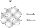
- These composite particles are composite particles in which a metal hydroxide capable of absorbing heat through an endothermic reaction and a flame retardant having a radical trapping ability are combined. As shown in FIG. 1 , these composite particles are combined after the metal hydroxide particles and the flame retardant are mixed as uniformly as possible. For example, a plurality of metal hydroxide particles including the flame retardant on the surface and inside are gathered together.
- the composite means, for example, a state in which a plurality of particles are formed into one aggregate by chemically bonding to each other through the functional groups (for example, hydroxyl and phosphate groups) possessed by each particle.
- the chemical bond herein includes not only covalent bonds but also various bonds such as ionic bonds, coordination bonds, and metallic bonds.
- the bonding state between particles can be confirmed by, for example, X-ray photoelectron spectroscopy.
- the particle diameter of the composite particles may be such that the integrated value of 50% (D 50 ) of the volume-based particle size distribution may be greater than or equal to about 0.1 ⁇ m and less than or equal to about 8 ⁇ m.
- the D 50 of the composite particle may be greater than or equal to about 0.5 ⁇ m and less than or equal to about 6 ⁇ m, and, for example, greater than or equal to about 1 ⁇ m and less than or equal to about 5 ⁇ m.
- the particle diameter of the composite particles can be controlled by the preparing conditions of the composite particles. For example, if the temperature for preparing composite particles is increased or the stirring speed is increased, the particle diameter of the composite particles tends to become smaller. For example, it is possible to make the particle diameter of the composite particles smaller than the particle diameter of the metal hydroxide that is the starting material.
- the metal hydroxide particles may be any endothermic material capable of causing an endothermic reaction and are not particularly limited.
- the metal hydroxides include aluminium hydroxide, pseudo-boehmite, boehmite, alumina, and kaolinite. These may be used alone, or two or more types may be used together.
- the integrated value of 50% (D 50 ) of the volume-based particle size distribution of the metal hydroxide particles may be greater than or equal to about 10 nm and less than or equal to about 10 ⁇ m, and, for example, greater than or equal to about 50 nm and less than or equal to about 5 ⁇ m.
- the flame retardant may be any that has a radical trapping ability to capture radicals such as oxygen radicals generated in the positive electrode mixture layer, and may include, for example, at least one type selected from phosphoric acid, phosphoric acid ester (such as phenyl phosphate and diphenyl phosphate), phosphonic acid (such as methyl phosphonic acid and phenyl phosphonic acid), and phosphinic acid (such as methyl phosphinic acid), which can form a functional group including a phosphorus (P) element by combining with the metal hydroxide.
- phosphoric acid ester such as phenyl phosphate and diphenyl phosphate
- phosphonic acid such as methyl phosphonic acid and phenyl phosphonic acid
- phosphinic acid such as methyl phosphinic acid
- a content of the metal hydroxide particles in the composite particles may be in the range of greater than or equal to about 1 mass% and less than or equal to about 50 mass%, greater than or equal to about 5 mass% and less than or equal to about 30 mass%, or greater than or equal to about 10 mass% and less than or equal to about 20 mass% based on the total weight of the composite particles (100 mass%).
- a content of the flame retardant in the composite particles may be in the range of greater than or equal to about 0.1 mass% and less than or equal to about 90 mass%, greater than or equal to about 1 mass% and less than or equal to about 85 mass%, or greater than or equal to about 10 mass% and less than or equal to about 80 mass% based on a total weight of the composite particles (100 mass%).
- a content of composite particles in the positive electrode mixture layer may be in the range of greater than or equal to about 0.1 mass% and less than or equal to about 5 mass%, greater than or equal to about 0.2 mass% and less than or equal to about 3 mass%, or greater than or equal to about 0.5 mass% and less than or equal to about 2 mass% based on a total weight of the positive electrode mixture layer.
- the content of the composite particles for a non-aqueous electrolyte rechargeable battery based on a total non-aqueous electrolyte rechargeable battery varies depending on the use of the non-aqueous electrolyte rechargeable battery and is not limited to the range below, but, for example, when the overall mass of the rechargeable battery is 100 mass%, the content of composite particles for non-aqueous electrolyte rechargeable batteries included in the non-aqueous electrolyte rechargeable battery may be greater than or equal to about 0.01 mass% and less than or equal to about 5.0 mass%, greater than or equal to about 0.02 mass% and less than or equal to about 2.0 mass%, or greater than or equal to about 0.1 mass% and less than or equal to about 0.5 mass%.
- the composite particles for a non-aqueous electrolyte rechargeable battery according to the present embodiment can be prepared by mixing metal hydroxide particles and a flame retardant and heating them.
- the mixing may be performed, for example, by dispersing the metal hydroxide particles and the flame retardant in an appropriate solvent and stirring them.
- the stirring speed may be greater than or equal to about 50 m/min and less than or equal to about 500 m/min, or, for example, greater than or equal to about 100 m/min and less than or equal to about 400 m/min.
- the composite particles can be obtained by heating the dispersion to a temperature of, for example, greater than or equal to about 40 °C and less than or equal to about 100 °C, reacting at this temperature for greater than or equal to about 1 hour and less than or equal to about 48 hours, and then filtering it with filter paper.
- the solvent may be water, or a mixture of water and an alcohol-based organic solvent such as ethanol or 2-propanol.
- the heating temperature may be greater than or equal to about 60 °C and less than or equal to about 80 °C, and the heating time (reaction time) may be greater than or equal to about 5 hours and less than or equal to about 30 hours.
- the fact that the particles produced as described above have become the target composite particles may be confirmed, for example, by an amount of various degassing due to various modifying groups being in the following range.
- the amount of P 2 gas desorbed from the composite particles measured by TDS-MS (referred to as MS1) may be greater than or equal to about 200 ⁇ 10 -6 mol/g and less than or equal to about 2500 ⁇ 10 -6 mol/g and the amount of desorbed H 2 O (referred to as MS2) may be greater than or equal to about 50 ⁇ 10 -6 mol/g and less than or equal to about 1000 ⁇ 10 -6 mol/g.
- MS1 may be greater than or equal to about 300 ⁇ 10 -6 mol/g and less than or equal to about 2000 ⁇ 10 -6 mol/g, or greater than or equal to about 400 ⁇ 10 -6 mol/g and less than or equal to about 1800 ⁇ 10 -6 mol/g.
- MS2 may be greater than or equal to about 100 ⁇ 10 -6 mol/g and less than or equal to about 950 ⁇ 10 -6 mol/g, or and greater than or equal to about 300 ⁇ 10 -6 mol/g and less than or equal to about 900 ⁇ 10 -6 mol/g.
- a ratio (M1/M2) of the amounts of these desorbed gases may be greater than or equal to about 0.5 and less than or equal to about 10.0, greater than or equal to about 0.5 and less than or equal to about 5.0, or greater than or equal to about 0.8 and less than or equal to about 3.0.
- a ratio of the amounts of desorbed gases may satisfy Formula (1): 0.5 ⁇ (MS1/MS2) ⁇ 10.0...(1).
- a specific surface area of the composite particles calculated by the adsorption isotherm measured by adsorbing nitrogen to the composite particles may be greater than or equal to about 8 m 2 /g and less than or equal to about 150 m 2 /g, greater than or equal to about 8 m 2 /g and less than or equal to about 80 m 2 /g, greater than or equal to about 10 m 2 /g and less than or equal to about 75 m 2 /g, or greater than or equal to about 15 m 2 /g and less than or equal to about 75 m 2 /g.
- the composite particles including flame retardant that is more modified to the metal hydroxide it is desirable to use a metal hydroxide as a starting material with as large a specific surface area as possible and to mix the metal hydroxide with a relatively large specific surface area with a flame retardant to set the specific surface area of the composite particles in the above-mentioned range.
- the specific surface area of the composite particles tends to decrease when the amount of flame retardant added to the metal hydroxide is increased or the reaction time when combining the metal hydroxide and flame retardant is lengthened.
- the specific surface area of the composite particles can be adjusted by changing these conditions, and thus the specific surface area of the metal hydroxide as the starting material is not particularly limited, but the specific surface area of the metal hydroxide may be, for example, greater than or equal to about 100 m 2 /g and less than or equal to about 500 m 2 /g.
- the content of Al (aluminium) element and P (phosphorus) element measured by inductively coupled plasma emission spectroscopy (ICP-AES) is within the following range.
- the content of Al element in the composite particles may be greater than or equal to about 1 mass% and less than or equal to about 50 mass%, greater than or equal to about 3 mass% and less than or equal to about 40 mass%, or greater than or equal to about 5 mass% and less than or equal to about 30 mass%.
- the content of P element in the composite particles may be greater than or equal to about 1 mass% and less than or equal to about 50 mass%, greater than or equal to about 3 mass% and less than or equal to about 40 mass%, or greater than or equal to about 5 mass% and less than or equal to about 30 mass%.
- the composite particles may be modified with functional groups such as CH 3 groups and CH 2 OH groups.
- a degree of modification by these functional groups may be evaluated by the following desorption amounts of various gases derived from these functional groups, in the same way as the degree of modification by functional groups including the phosphorus (P) element (e.g., phosphonic acid). It is desirable that the desorption amounts of various gases satisfy the following ranges. On the other hand, the desorption amounts of various gases can be adjusted depending on the type and content of the metal hydroxide and flame retardant used in preparing the composite particles.
- the amount (referred to as MS3) of desorbed CH 4 gas measured by TDS-MS which is the amount of CH 4 gas desorbed from the composite particle when the composite particle is heated from about 80 °C to about 1400 °C, may be 0, but it may exceed 0 and be less than or equal to about 1000 ⁇ 10 -6 mol/g, greater than or equal to about 10 ⁇ 10 -6 mol/g and less than or equal to about 700 ⁇ 10 -6 mol/g, or greater than or equal to about 30 ⁇ 10 -6 mol/g and less than or equal to about 500 ⁇ 10 -6 mol/g.
- the amount of desorbed CHsOH (referred to as MS4) measured may be 0, but it may exceed 0 and be less than or equal to about 4000 ⁇ 10 -6 mol/g, greater than or equal to about 200 ⁇ 10 -6 mol/g and less than or equal to about 3000 ⁇ 10 -6 mol/g, or greater than or equal to about 500 ⁇ 10 -6 mol/g and less than or equal to about 3000 ⁇ 10 -6 mol/g.
- the composite particles are modified with a functional group including a phenyl group, it is easy to disperse the metal hydroxide particles in the solvent when preparing a slurry using a non-aqueous solvent such as N-methyl-2-pyrrolidone (NMP).
- NMP N-methyl-2-pyrrolidone
- the amount (referred to as MS5) of desorbed C 6 H 6 from about 80 °C to about 1400 °C by TDS-MS of the metal hydroxide particles may be 0, but may be greater than 0 and less than or equal to about 4000 ⁇ 10 -6 mol/g, greater than or equal to about 10 ⁇ 10 -6 mol/g and less than or equal to about 3000 ⁇ 10 -6 mol/g, or greater than or equal to about 100 ⁇ 10 -6 mol/g and less than or equal to about 3000 ⁇ 10 -6 mol/g.
- the total content of modified molecules in the composite particles may be in the range of greater than or equal to about 10 mass% and less than or equal to about 99 mass%, greater than or equal to about 20 mass% and less than or equal to about 97 mass%, or greater than or equal to about 30 mass% and less than or equal to about 95 mass% based on 100 mass% of the total composite particles.
- the positive electrode is produced as follows. First, a positive electrode slurry is formed by dispersing a mixture of a positive electrode active material, a conductive agent, a positive electrode binder, and composite particles in a desired ratio in a solvent for a positive electrode slurry. Next, this positive electrode slurry is coated on the positive electrode current collector and dried to form a positive electrode mixture layer.
- the coating method is not particularly limited. The coating method may include a knife coater method, a gravure coater method, a reverse roll coater, a slit die coater, and the like. Each of the following coating processes is also performed by the same method. Subsequently, the positive electrode material mixture layer is pressed by a press to have a desired density. Thus, a positive electrode is manufactured.
- the negative electrode is also produced in the same way as the positive electrode.
- a negative electrode slurry is prepared by dispersing a mixture of materials constituting the negative electrode mixture layer in a solvent for a negative electrode slurry.
- a negative electrode mixture layer is formed by coating the negative electrode slurry on the negative current collector and drying it.
- the negative electrode material mixture layer is pressed by a press machine so as to have a desired density.
- a negative electrode is manufactured.
- an electrode structure is manufactured by placing a separator between the positive electrode and the negative electrode. Then, the electrode structure may be processed into a desired shape (e.g., cylindrical shape, prismatic shape, laminated shape, button shape, etc.) and inserted into a container of the above shape. Subsequently, a non-aqueous electrolyte is inserted into the corresponding container to impregnate the electrolyte into each pore in the separator or a gap between the positive electrode and negative electrode. Accordingly, a rechargeable lithium ion battery is manufactured.
- a desired shape e.g., cylindrical shape, prismatic shape, laminated shape, button shape, etc.
- the increase in the internal temperature of the non-aqueous electrolyte rechargeable battery may be sufficiently suppressed, electrical resistance of the non-aqueous electrolyte rechargeable battery may be suppressed to a small level, and cycle characteristics may be improved.
- the positive electrode includes the composite particles according to the present invention
- the negative electrode may also include the composite particles.
- composite particles may be included in the electrolyte, or may be included in multiple locations in the positive electrode, negative electrode, and electrolyte.
- a content of the composite particles for a non-aqueous electrolyte rechargeable battery based on a total negative electrode may be in the same range as that for the positive electrode.
- a content of the composite particles for a non-aqueous electrolyte rechargeable battery when the mass of the total electrolyte is 100 mass% may be in the range of about 0.1 mass% to about 10.0 mass%.
- Composite particles B were obtained in the same manner as in Example 1, except that 1.0 g of activated alumina (D 50 : 3 ⁇ m, BET: 300 m 2 /g, Manufacturer: Zibo Yinghe Chemical Co., Ltd.) and 5.0 g of methyl phosphonic acid were used as starting materials.
- Composite particles C were obtained in the same manner as in Example 1, except that 1.0 g of pseudo-boehmite (D 50 : 1.8 ⁇ m, BET: 384 m 2 /g, Manufacturer: Zibo Linxi Chemical Co., Ltd.) and 5.0 g of diphenyl phosphate were used as starting materials.
- Composite particles D were obtained in the same manner as in Example 1, except that 1.0 g of kaolinite (Al 2 Si 2 O 5 (OH) 4 , D 50 : 1 ⁇ m, BET: 120 m 2 /g, Manufacturer: Hebei Jinshi New Materials Technology Co., Ltd.) and 5.0 g of phenyl phosphate were used as starting materials.
- 1.0 g of kaolinite (Al 2 Si 2 O 5 (OH) 4 , D 50 : 1 ⁇ m, BET: 120 m 2 /g, Manufacturer: Hebei Jinshi New Materials Technology Co., Ltd.) and 5.0 g of phenyl phosphate were used as starting materials.
- Composite particles E were obtained in the same manner as in Example 1, except that 1.0 g of pseudo-boehmite (D 50 : 1.8 ⁇ m, BET: 384 m 2 /g, Manufacturer: Zibo Linxi Chemical Co., Ltd.) and 5.0 g of phenyl phosphonic acid were used as starting materials.
- Composite particles F were obtained in the same manner as in Example 1, except that 1.0 g of pseudo-boehmite (D 50 : 1.8 ⁇ m, BET: 384 m 2 /g, Manufacturer: Zibo Linxi Chemical Co., Ltd.) and 1.0 g of diphenyl phosphate were used as starting materials.
- Composite particles F were obtained in the same manner as in Example 1, except that 1.0 g of pseudo-boehmite (D 50 : 1.8 ⁇ m, BET: 384 m 2 /g, Manufacturer: Zibo Linxi Chemical Co., Ltd.) and 1.0 g of phenyl phosphate were used as starting materials.
- Composite particles H were obtained in the same manner as in Example 1, except that 1.0 g of pseudo-boehmite (D 50 : 1.8 ⁇ m, BET: 384 m 2 /g, Manufacturer: Zibo Linxi Chemical Co., Ltd.) and 5.0 g of methyl phosphinic acid were used as starting materials.
- Composite particles I were obtained in the same manner as in Example 1, except that 1.0 g of pseudo-boehmite (D 50 : 1.8 ⁇ m, BET: 384 m 2 /g, Manufacturer: Zibo Linxi Chemical Co., Ltd.) and 5.0 g of phosphoric acid were used as starting materials.
- Composite particles J were obtained in the same manner as in Example 1, except that 1.0 g of kaolinite (Al 2 Si 2 O 5 (OH) 4 , D 50 : 1 ⁇ m, BET: 120 m 2 /g, Manufacturer: Hebei Jinshi New Materials Technology Co., Ltd.) and 5.0 g of phenyl phosphonic acid were used as starting materials.
- Composite particles K were obtained in the same manner as in Example 1, except that 1.0 g of kaolinite (Al 2 Si 2 O 5 (OH) 4 , D 50 : 1 ⁇ m, BET: 120 m 2 /g, Manufacturer: Hebei Jinshi New Materials Technology Co., Ltd.) and 5.0 g of methyl phosphonic acid were used as starting materials.
- Composite particles L were obtained in the same manner as in Example 1, except that 1.0 g of kaolinite (Al 2 Si 2 O 5 (OH) 4 , D 50 : 1 ⁇ m, BET: 120 m 2 /g, Manufacturer: Hebei Jinshi New Materials Technology Co., Ltd.) and 5.0 g of methyl phosphinic acid were used as starting materials.
- Composite particles M were obtained in the same manner as in Example 1, except that 1.0 g of aluminium hydroxide (D 50 : 3 ⁇ m, BET: 205 m 2 /g, Manufacturer: Iwatani Chemical Industry Co., Ltd.) and 5.0 g of methyl phosphonic acid were used as starting materials.
- Composite particles N were obtained in the same manner as in Example 1, except that 1.0 g of aluminium hydroxide (D 50 : 3 ⁇ m, BET: 205 m 2 /g, Manufacturer: Iwatani Chemical Industry Co., Ltd.) and 5.0 g of phenyl phosphonic acid were used as starting materials.
- Composite particles O were obtained in the same manner as in Example 1, except that 1.0 g of activated alumina (D 50 : 3 ⁇ m, BET: 300 m 2 /g, Manufacturer: Zibo Yinghe Chemical Co., Ltd.) and 5.0 g of methyl phosphinic acid were used as starting materials.
- Composite particles P were obtained in the same manner as in Example 1, except that 1.0 g of activated alumina (D 50 : 3 ⁇ m, BET: 300 m 2 /g, Manufacturer: Zibo Yinghe Chemical Co., Ltd.) and 5.0 g of phenyl phosphonic acid were used as starting materials.
- Composite particles Q were obtained in the same manner as in Example 1, except that 1.0 g of aluminium hydroxide (D 50 : 18 ⁇ m, BET: 125 m 2 /g, Manufacturer: Iwatani Chemical Industry Co., Ltd.) and 2.0 g of methyl phosphonic acid were used as starting materials.
- LiCoO 2 , acetylene black, and polyvinylidene fluoride the composite particles, endothermic particles, particle mixtures, or radical scavengers listed in Table 1 (composite particles, endothermic particles, particle mixtures, or radical scavengers are collectively referred to as heat suppressing additives), and polyvinylidene fluoride as a binder were dispersed and mixed in a form of dry powders (solid content) including no solvent in N-methyl-2-pyrrolidone solvent to prepare positive electrode mixture slurries.
- the slurry is coated on one surface or both surfaces of the aluminium current collector so that the mixture application amount (surface density) after drying is 20.0 mg/cm 2 on one surface, dried, and then pressed with a roll press machine so that the positive electrode mixture layer density was 4.15 g/cc to form a positive electrode mixture layer.
- a positive electrode was manufactured in the same manner as in Example 1, except that LiCoO 2 , acetylene black, and polyvinylidene fluoride were dispersed and mixed in N-methyl-2-pyrrolidone solvent in a mass ratio of 97.7:1.0:1.3 as a dry powder (solid content) including no solvent to prepare a positive electrode mixture slurry.
- a plurality of the positive electrodes and a plurality of the negative electrode were stacked with a polypropylene porous separator between the positive and negative electrodes to have battery design capacity of 300 mAh, manufacturing an electrode stack.
- a mixture layer formed on both surfaces of the current collector were used, and for the positive electrode or negative electrode disposed on the outermost layer, a mixture layer formed on only one surface was used.
- a positive electrode with an electrode plate area of 8.5 cm 2 (both surfaces, 5 sheets) and a negative electrode with an electrode plate area of 10.0 cm 2 (4 sheets of both surfaces and 2 sheets of one surface) were manufactured.
- a rechargeable battery cell before the initial charge was manufactured by welding nickel and aluminium lead wires respectively to the negative and positive electrodes of the electrode stack, housing the electrode stack in an aluminium laminate film with the lead wires externally pulled out, injecting an electrolyte thereinto, and sealing the aluminium laminate film under a reduced pressure.
- the electrolyte was prepared by dissolving 1.3 M LiPF 6 and 1 mass% of vinylene carbonate in a mixed solvent of ethylene carbonate / dimethyl carbonate / fluoroethylene carbonate in a volume ratio of 15/80/5.
- the specific surface area (BET calculated based on the adsorption isotherm measured by adsorbing water vapor) of the inorganic particles or composite particles was measured using a gas adsorption amount measuring device (BELSORP manufactured by Microtrac Bell), according to JIS K6217-2.
- TDS-MS Thermal desorption gas mass spectrometry
- the sample materials were set by using a sample stage made of quartz and a sample dish made of SiC.
- the temperature increase rate was 60 °C/min.
- the temperature increase was controlled by monitoring a temperature on the sample surface.
- a weight of the sample was 1 mg, which was corrected by an actual weight.
- a quadruple mass spectrometer was used for a detection, and a voltage applied thereto was 1000 V.
- TDS was used to measure an amount ( ⁇ mol/g) of each gas desorbed from the inorganic particles or composite particles during the temperature increase from 80 °C to 1400° C.
- the mass number [M/z] used for analyzing the measurements was 15 for CH 4 , 18 for H 2 O, 31 for CHsOH, 62 for P 2 , and 78 for C 6 H 6 , wherein gases corresponding to the mass numbers were all each of the aforementioned substances.
- gas amount of H 2 O an integrated value only from 80 °C to 200 °C out of the entire temperature range was used to obtain the desorbed H 2 O amount (MS2).
- the particle diameter of the composite particle, endothermic particle, or particle mixture was evaluated as D 50 , 50% of the integrated value of the particle size distribution based on the particle diameter volume in the particle size distribution obtained by laser diffraction/scattering method. D 50 was measured using the following equipment and conditions.
- the rechargeable battery cells according to Examples 1 to 16 and Comparative Examples 1 to 7 were charged under a constant current to 4.3 V at 0.1 CA of design capacity and charged under a constant voltage to 0.05 CA still at 4.3 V in a 25 °C thermostat. Subsequently, the cells were discharged under a constant current to 3.0 V at 0.1 CA. In addition, the cells were measured with respect to initial discharge capacity after the 1 st cycle through a constant current charge at 0.2 CA, a constant voltage charge at 0.05 CA, and a constant current discharge at 0.2 CA under conditions of a charge cut-off voltage of 4.3 V and a discharge cut-off voltage of 3.0 V in the 25 °C thermostat.
- the rechargeable battery cells were 100 cycles charged and discharged through a constant current charge at 0.5 CA, a constant voltage charge at 0.05 CA, and a constant current discharge 0.5 CA under conditions of a charge cut-off voltage of 4.3 V and a discharge cut-off voltage of 3.0 V at 45 °C to test a cycle-life. After the 100 cycles, discharge capacity at a constant current charge of 0.2 CA, a constant voltage charge of 0.05 CA, and a discharge at 0.2 CA of the cells was measured and was divided by the initial discharge capacity to obtain capacity retention after the 100 cycles.
- the rechargeable battery cells according to Examples 1 to 16 and Comparative Examples 1 to 7 were charged under a constant current to 4.3 V at design capacity of 0.1 CA and charged under a constant voltage at 4.3 V to 0.05 CA in the 25 °C thermostat. Subsequently, the cells were discharged to 3.0 V at 0.1 CA under a constant current. In addition, in the 25 °C thermostat, after performing a constant current charge at 0.2 CA, a constant voltage charge at 0.05 CA, and a constant current discharge at 0.2 CA under conditions of a charge cut-off voltage of 4.3 V and a discharge cut-off voltage of 3.0 V as 1 cycle, the cells were charged again under a constant current/constant voltage to 4.42 V, which were regarded as initial cells.
- a nail penetration test was conducted by penetrating the aforementioned initial cells in the center with a nail having a diameter of 3 mm at 1 mm/s.
- a case where an external temperature of a battery cell reached 50 °C or higher 5 seconds after being penetrated with the nail was regarded as "abnormal occurrence," and an abnormal occurrence rate was evaluated in 10 individual battery tests.
- Composite particle A 3.5 21 17 20 1210 571 2.1 35 267 11 Ex. 2 Composite particle B 7.0 68 11 26 1613 851 1.9 35 267 12 Ex. 3 Composite particle C 1.8 58 8 9 583 721 0.8 418 2941 2841 Ex. 4 Composite particle D 1.1 48 6 15 904 751 1.2 209 1612 1475 Ex. 5 Composite particle E 0.2 28 7 16 987 734 1.3 209 1601 1473 Ex. 6 Composite particle F 1.5 74 21 12 740 871 0.8 35 267 10 Ex. 7 Composite particle G 1.6 51 6 15 910 721 1.3 221 1588 1489 Ex. 8 Composite particle H 1.7 21 17 20 1189 621 1.9 45 281 21 Ex.
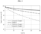
- FIG. 2 a graph of the discharge capacity retention rates for the rechargeable battery cells manufactured in Example 6, Comparative Example 1, Comparative Example 3, and Comparative Example 4 shown in Tables 1 and 2 is shown in FIG. 2 .
- Example 2 The initial cells of the fully charged rechargeable battery cells manufactured in Example 2 and Comparative Example 1 shown in Table 1 and Table 2 were disassembled in a glove box, and the positive electrodes were washed with dimethyl carbonate solvent and dried, and the obtained positive electrodes were used as a "charged positive electrode.”
- Comparative Example 5 which includes composite particles as a heat suppressing additive but has a D 50 of 13 ⁇ m
- Comparative Examples 6 and 7 which include a particle mixture including the same components as the composite particles according to the present invention
- composite particles having both an endothermic effect and radical scavenging ability are made, and the D 50 range of the composite particles is appropriately adjusted to increase the density of the positive electrode active material particles in the positive electrode mixture layer as much as possible. It is possible to arrange as many composite particles as possible around the positive electrode active material particles without deterioration. As a result, oxygen and radicals generated from the positive electrode active material are captured in the temperature range of 150 °C to 300 °C, and the decomposition reaction of the electrolyte is effectively suppressed, thereby sufficiently suppressing the increase in the internal temperature of the battery and suppressing deterioration of battery performance such as cycle characteristics.
- a battery management system (BMS) device and/or any other relevant devices or components according to embodiments of the present disclosure described herein may be implemented utilizing any suitable hardware, firmware (e.g., an application-specific integrated circuit), software, or a combination of software, firmware, and hardware.
- the various components of the device may be formed on one integrated circuit (IC) chip or on separate IC chips.
- the various components of the device may be implemented on a flexible printed circuit film, a tape carrier package (TCP), a printed circuit board (PCB), or formed on one substrate.
- the various components of the device may be a process or thread, running on one or more processors, in one or more computing devices, executing computer program instructions and interacting with other system components for performing the various functionalities described herein.
- the computer program instructions are stored in a memory which may be implemented in a computing device using a standard memory device, such as, for example, a random access memory (RAM).
- the computer program instructions may also be stored in other non-transitory computer readable media such as, for example, a CD-ROM, flash drive, or the like.
- a person of skill in the art should recognize that the functionality of various computing devices may be combined or integrated into a single computing device, or the functionality of a particular computing device may be distributed across one or more other computing devices without departing from the scope of the present disclosure.
Landscapes
- Chemical & Material Sciences (AREA)
- Chemical Kinetics & Catalysis (AREA)
- Electrochemistry (AREA)
- General Chemical & Material Sciences (AREA)
- Engineering & Computer Science (AREA)
- Composite Materials (AREA)
- Materials Engineering (AREA)
- Manufacturing & Machinery (AREA)
- Inorganic Chemistry (AREA)
- Battery Electrode And Active Subsutance (AREA)
- Secondary Cells (AREA)
Applications Claiming Priority (1)
| Application Number | Priority Date | Filing Date | Title |
|---|---|---|---|
| JP2023005601A JP2024101606A (ja) | 2023-01-18 | 2023-01-18 | 非水電解質二次電池用複合粒子及び非水電解質二次電池 |
Publications (1)
| Publication Number | Publication Date |
|---|---|
| EP4407705A1 true EP4407705A1 (de) | 2024-07-31 |
Family
ID=89661216
Family Applications (1)
| Application Number | Title | Priority Date | Filing Date |
|---|---|---|---|
| EP24152704.3A Pending EP4407705A1 (de) | 2023-01-18 | 2024-01-18 | Verbundpartikel für eine wiederaufladbare batterie und wiederaufladbare batterie damit |
Country Status (4)
| Country | Link |
|---|---|
| US (1) | US20240243254A1 (de) |
| EP (1) | EP4407705A1 (de) |
| JP (1) | JP2024101606A (de) |
| KR (1) | KR20240115197A (de) |
Cited By (1)
| Publication number | Priority date | Publication date | Assignee | Title |
|---|---|---|---|---|
| EP4510243A1 (de) * | 2023-08-14 | 2025-02-19 | Samsung Sdi Co., Ltd. | Kompositpartikel für wiederaufladbare batterien mit nichtwässrigem elektrolyt, verfahren zu ihrer herstellung, positive elektroden und wiederaufladbare batterien mit nichtwässrigem elektrolyt |
Citations (6)
| Publication number | Priority date | Publication date | Assignee | Title |
|---|---|---|---|---|
| JP2011159484A (ja) | 2010-02-01 | 2011-08-18 | Hitachi Ltd | リチウム二次電池 |
| JP2011258481A (ja) | 2010-06-11 | 2011-12-22 | Hitachi Ltd | リチウムイオン電池 |
| JP2016162528A (ja) | 2015-02-27 | 2016-09-05 | ソニー株式会社 | 電解質、電池、電池パック、電子機器、電動車両、蓄電装置および電力システム |
| EP3675230A1 (de) * | 2018-05-15 | 2020-07-01 | Lg Chem, Ltd. | Mikrokapseln, separator damit und elektrochemische vorrichtung damit |
| CN111916637A (zh) * | 2020-07-31 | 2020-11-10 | 江苏厚生新能源科技有限公司 | 具有阻燃涂层的聚烯烃微孔膜及其制备方法、锂电池 |
| EP4254546A1 (de) * | 2022-03-31 | 2023-10-04 | Samsung SDI Co., Ltd. | Verbundpartikel für wiederaufladbare batterie mit nichtwässrigem elektrolyt, herstellungsverfahren, positive und negative elektroden und wiederaufladbare batterie mit nichtwässrigem elektrolyt |
-
2023
- 2023-01-18 JP JP2023005601A patent/JP2024101606A/ja active Pending
-
2024
- 2024-01-18 US US18/416,685 patent/US20240243254A1/en active Pending
- 2024-01-18 EP EP24152704.3A patent/EP4407705A1/de active Pending
- 2024-01-18 KR KR1020240008389A patent/KR20240115197A/ko active Pending
Patent Citations (6)
| Publication number | Priority date | Publication date | Assignee | Title |
|---|---|---|---|---|
| JP2011159484A (ja) | 2010-02-01 | 2011-08-18 | Hitachi Ltd | リチウム二次電池 |
| JP2011258481A (ja) | 2010-06-11 | 2011-12-22 | Hitachi Ltd | リチウムイオン電池 |
| JP2016162528A (ja) | 2015-02-27 | 2016-09-05 | ソニー株式会社 | 電解質、電池、電池パック、電子機器、電動車両、蓄電装置および電力システム |
| EP3675230A1 (de) * | 2018-05-15 | 2020-07-01 | Lg Chem, Ltd. | Mikrokapseln, separator damit und elektrochemische vorrichtung damit |
| CN111916637A (zh) * | 2020-07-31 | 2020-11-10 | 江苏厚生新能源科技有限公司 | 具有阻燃涂层的聚烯烃微孔膜及其制备方法、锂电池 |
| EP4254546A1 (de) * | 2022-03-31 | 2023-10-04 | Samsung SDI Co., Ltd. | Verbundpartikel für wiederaufladbare batterie mit nichtwässrigem elektrolyt, herstellungsverfahren, positive und negative elektroden und wiederaufladbare batterie mit nichtwässrigem elektrolyt |
Cited By (1)
| Publication number | Priority date | Publication date | Assignee | Title |
|---|---|---|---|---|
| EP4510243A1 (de) * | 2023-08-14 | 2025-02-19 | Samsung Sdi Co., Ltd. | Kompositpartikel für wiederaufladbare batterien mit nichtwässrigem elektrolyt, verfahren zu ihrer herstellung, positive elektroden und wiederaufladbare batterien mit nichtwässrigem elektrolyt |
Also Published As
| Publication number | Publication date |
|---|---|
| US20240243254A1 (en) | 2024-07-18 |
| KR20240115197A (ko) | 2024-07-25 |
| JP2024101606A (ja) | 2024-07-30 |
Similar Documents
| Publication | Publication Date | Title |
|---|---|---|
| EP3226331B1 (de) | Positivelektrodenaktivmaterial für sekundärbatterie mit wasserfreiem elektrolyten und herstellungsverfahren dafür und sekundärbatterie mit wasserfreiem elektrolyten mit verwendung des besagten positivelektrodenaktivmaterials | |
| EP2819226A1 (de) | Positivelektrodenmaterial für eine sekundärbatterie mit wasserfreiem elektrolyt, herstellungsverfahren dafür und sekundärbatterie mit wasserfreiem elektrolyt mit diesem positivelektrodenmaterial | |
| EP4254546A1 (de) | Verbundpartikel für wiederaufladbare batterie mit nichtwässrigem elektrolyt, herstellungsverfahren, positive und negative elektroden und wiederaufladbare batterie mit nichtwässrigem elektrolyt | |
| EP3951940A1 (de) | Verfahren zur herstellung eines kathodenaktivmaterials für eine lithiumsekundärbatterie und nach dem herstellungsverfahren hergestelltes kathodenaktivmaterial | |
| KR20240014046A (ko) | 복합체 입자, 부극 합제층 및 리튬 이온 이차 전지 | |
| EP4404309A1 (de) | Positive elektrode für wiederaufladbare batterie mit nichtwässrigem elektrolyt und wiederaufladbare batterie mit nichtwässrigem elektrolyt damit | |
| EP3780175B1 (de) | Positivelektrodenaktivmaterial für sekundärbatterie mit wasserfreiem elektrolyt | |
| CN116830310A (zh) | 非水电解质电池及电池包 | |
| US20210193399A1 (en) | Positive electrode for power storage device and power storage device | |
| EP4407705A1 (de) | Verbundpartikel für eine wiederaufladbare batterie und wiederaufladbare batterie damit | |
| EP4207371A1 (de) | Positivelektrode, elektrochemische vorrichtung und elektronische vorrichtung | |
| EP4148832A1 (de) | Negativelektrodenmaterial für eine lithium-ionen-sekundärbatterie, negativelektrode für eine lithium-ionen-sekundärbatterie und lithium-ionen-sekundärbatterie | |
| US20250183289A2 (en) | Positive electrode for non-aqueous electrolyte, rechargeable battery, and non-aqueous electrolyte rechargeable battery | |
| EP4020634A1 (de) | Poröse anorganische teilchen und batterie damit | |
| EP4270540A1 (de) | Negativelektrodenmaterial, elektrodenplatte mit dem negativelektrodenmaterial und elektrochemische vorrichtung | |
| EP4471904A1 (de) | Sekundärbatterie und elektronische vorrichtung | |
| EP4510243A1 (de) | Kompositpartikel für wiederaufladbare batterien mit nichtwässrigem elektrolyt, verfahren zu ihrer herstellung, positive elektroden und wiederaufladbare batterien mit nichtwässrigem elektrolyt | |
| EP4276932A1 (de) | Endotherme partikel für wiederaufladbare batterie mit nichtwässrigem elektrolyt und wiederaufladbare batterie mit nichtwässrigem elektrolyt | |
| EP4700840A1 (de) | Positive elektrode für eine wiederaufladbare batterie mit nichtwässrigem elektrolyt und wiederaufladbare batterie mit nichtwässrigem elektrolyt | |
| EP4704168A1 (de) | Positivelektrode für eine sekundärbatterie mit wasserfreiem elektrolyt und verfahren zur herstellung einer positivelektrode für eine sekundärbatterie mit wasserfreiem elektrolyt | |
| KR20260029241A (ko) | 비수전해질 이차 전지용 양극 및 비수전해질 이차 전지 | |
| KR20250025310A (ko) | 비수전해질 이차 전지용 복합 입자 및 비수전해질 이차 전지 | |
| EP4576390A1 (de) | Separator und sekundärbatterie damit | |
| EP4074659A2 (de) | Kathodenaktivmaterial für eine lithiumsekundärbatterie, kathode damit und lithiumsekundärbatterie damit | |
| JP2023150446A (ja) | 非水電解質二次電池用複合粒子及び非水電解質二次電池 |
Legal Events
| Date | Code | Title | Description |
|---|---|---|---|
| PUAI | Public reference made under article 153(3) epc to a published international application that has entered the european phase |
Free format text: ORIGINAL CODE: 0009012 |
|
| STAA | Information on the status of an ep patent application or granted ep patent |
Free format text: STATUS: REQUEST FOR EXAMINATION WAS MADE |
|
| 17P | Request for examination filed |
Effective date: 20240118 |
|
| AK | Designated contracting states |
Kind code of ref document: A1 Designated state(s): AL AT BE BG CH CY CZ DE DK EE ES FI FR GB GR HR HU IE IS IT LI LT LU LV MC ME MK MT NL NO PL PT RO RS SE SI SK SM TR |