EP4407447A1 - Verfahren und vorrichtung zur erzeugung von zuordnungsbeziehungen und speichermedium - Google Patents
Verfahren und vorrichtung zur erzeugung von zuordnungsbeziehungen und speichermedium Download PDFInfo
- Publication number
- EP4407447A1 EP4407447A1 EP21960968.2A EP21960968A EP4407447A1 EP 4407447 A1 EP4407447 A1 EP 4407447A1 EP 21960968 A EP21960968 A EP 21960968A EP 4407447 A1 EP4407447 A1 EP 4407447A1
- Authority
- EP
- European Patent Office
- Prior art keywords
- mapping relationship
- communication connector
- node
- network domain
- information
- Prior art date
- Legal status (The legal status is an assumption and is not a legal conclusion. Google has not performed a legal analysis and makes no representation as to the accuracy of the status listed.)
- Pending
Links
Images



Classifications
-
- H—ELECTRICITY
- H04—ELECTRIC COMMUNICATION TECHNIQUE
- H04L—TRANSMISSION OF DIGITAL INFORMATION, e.g. TELEGRAPHIC COMMUNICATION
- H04L41/00—Arrangements for maintenance, administration or management of data switching networks, e.g. of packet switching networks
- H04L41/12—Discovery or management of network topologies
-
- H—ELECTRICITY
- H04—ELECTRIC COMMUNICATION TECHNIQUE
- H04L—TRANSMISSION OF DIGITAL INFORMATION, e.g. TELEGRAPHIC COMMUNICATION
- H04L41/00—Arrangements for maintenance, administration or management of data switching networks, e.g. of packet switching networks
- H04L41/50—Network service management, e.g. ensuring proper service fulfilment according to agreements
-
- G—PHYSICS
- G06—COMPUTING OR CALCULATING; COUNTING
- G06F—ELECTRIC DIGITAL DATA PROCESSING
- G06F9/00—Arrangements for program control, e.g. control units
- G06F9/06—Arrangements for program control, e.g. control units using stored programs, i.e. using an internal store of processing equipment to receive or retain programs
- G06F9/44—Arrangements for executing specific programs
Definitions
- This application relates to the field of intelligent vehicles, and in particular, to a mapping relationship generation method and apparatus, and a storage medium.
- An automotive open system architecture (automotive open system architecture, AUTOSAR) is an open and de facto standardized software architecture developed to reduce development risks of automotive software.
- AUTOSAR automotive open system architecture
- a vehicle that integrates a plurality of auxiliary functions such as sensing, planning and control, and automatic cruise is a typical high-tech complex. Therefore, the vehicle is increasingly intelligent and electronic, and a software structure of the vehicle is increasingly complex.
- An adaptive platform (Adaptive Platform) is developed in the AUTOSAR based on an original classic platform (Classic Platform).
- Communication management (communication management, CM) is a top priority of the AUTOSAR adaptive platform.
- CM communication management
- a series of mapping relationships usually need to be established for a communication service after the communication service is instantiated.
- a common case is to establish a mapping relationship manually for each instance one by one. This is complex and inefficient.
- mapping relationship generation method and apparatus and a storage medium are proposed.
- an embodiment of this application provides a mapping relationship generation method.
- the method includes: obtaining information about a mapping relationship between a communication connector on a node and a network domain; obtaining information about a mapping relationship between a process and the node, where the information about the mapping relationship between the process and the node includes a software component corresponding to the process, and the software component includes at least one port prototype; and creating, based on the information about the mapping relationship between the communication connector on the node and the network domain and the information about the mapping relationship between the process and the node, a service instance for the port prototype used by the process in the network domain, and creating a mapping relationship between the service instance and a target communication connector on the node.
- the service instance is created for the port prototype used by the process in the network domain, to create the mapping relationship between the service instance and the target communication connector on the node.
- the mapping relationship can be established between the service instance created in the network domain and the target communication connector without a manual operation, so that a corresponding node can communicate with the service instance, and the mapping relationship does not need to be manually established. This simplifies a configuration procedure and improves configuration efficiency.
- the method further includes: creating the network domain, and configuring the information about the mapping relationship between the communication connector on the node and the network domain.
- the method further includes: configuring the mapping relationship between the process and the node, and allocating the corresponding software component to the process.
- an association relationship between the process and the software component can be determined, so that the mapping relationship between the service instance in the network domain and the target communication connector can be automatically created subsequently.
- the method further includes: configuring the port prototype used by the process to communicate with another process in the network domain.
- the creating the network domain, and configuring the information about the mapping relationship between the communication connector on the node and the network domain includes: determining an ID of the network domain.
- the creating, based on the information about the mapping relationship between the communication connector on the node and the network domain and the information about the mapping relationship between the process and the node, a service instance for the port prototype used by the process in the network domain, and creating a mapping relationship between the service instance and a target communication connector on the node includes: when a communication protocol of the service instance is a data distribution service DDS, determining that a network domain ID associated with the service instance is the ID.
- the ID of the network domain is determined, so that when the communication protocol is the DDS, the service instance can be associated with the network domain ID without a need of manual setting. This simplifies a configuration process and improves configuration efficiency.
- each communication connector is associated with an internet protocol IP address.
- the node can communicate with another configured object through the communication connector.
- the creating, based on the information about the mapping relationship between the communication connector on the node and the network domain and the information about the mapping relationship between the process and the node, a service instance for the port prototype used by the process in the network domain, and creating a mapping relationship between the service instance and a target communication connector on the node includes: determining, based on the information about the mapping relationship between the communication connector on the node and the network domain, a first communication connector information set corresponding to the network domain, where the first communication connector information set includes at least one communication connector on the node; determining, based on information about a mapping relationship between the service instance and the port prototype of the software component, a second communication connector information set corresponding to the port prototype of the software component, where the second communication connector information set includes at least one communication connector on a target node; and determining the mapping relationship between the service instance and the target communication connector based on the first
- two communication connector information sets are determined, to determine the target communication connector, and the target communication connector does not need to be manually searched for, so that the mapping relationship between the service instance and the target communication connector can be established in a configuration process, and the mapping relationship does not need to be manually established, to implement mapping from the service instance to the node. This simplifies the configuration procedure and improves efficiency.
- the creating the mapping relationship between the service instance and the target communication connector based on the first communication connector information set and the second communication connector information set includes: determining the target communication connector based on an intersection set of the first communication connector information set and the second communication connector information set; and creating the mapping relationship between the service instance and the target communication connector.
- mapping relationship between the service instance and the target communication connector can be determined without a need of manually searching for the target communication connector corresponding to the service instance, to implement communication between the service instance and the target node. This simplifies the configuration procedure and improves efficiency.
- the method is used to configure a communication service in an automotive open system architecture AUTOSAR adaptive platform.
- this method can be applied to a vehicle, so that configuration of communication management CM can be more efficiently implemented on the AUTOSAR adaptive platform, to apply a corresponding communication service.
- an embodiment of this application provides a mapping relationship generation apparatus.
- the apparatus includes: a first obtaining module, configured to obtain information about a mapping relationship between a communication connector on a node and a network domain; a second obtaining module, configured to obtain information about a mapping relationship between a process and the node, where the information about the mapping relationship between the process and the node includes a software component corresponding to the process, and the software component includes at least one port prototype; and a creating module, configured to: create, based on the information about the mapping relationship between the communication connector on the node and the network domain and the information about the mapping relationship between the process and the node, a service instance for the port prototype used by the process in the network domain, and create a mapping relationship between the service instance and a target communication connector on the node.
- the apparatus further includes: a first configuration module, configured to: create the network domain, and configure the information about the mapping relationship between the communication connector on the node and the network domain.
- the apparatus further includes: a second configuration module, configured to: configure the mapping relationship between the process and the node, and allocate the corresponding software component to the process.
- the apparatus further includes: a third configuration module, configured to configure the port prototype used by the process to communicate with another process in the network domain.
- the first configuration module includes: determining an ID of the network domain; and the creating module includes: when a communication protocol of the service instance is a data distribution service DDS, determining that a network domain ID associated with the service instance is the ID.
- each communication connector is associated with an internet protocol IP address.
- the creating module includes: determining, based on the information about the mapping relationship between the communication connector on the node and the network domain, a first communication connector information set corresponding to the network domain, where the first communication connector information set includes at least one communication connector on the node; determining, based on information about a mapping relationship between the service instance and the port prototype of the software component, a second communication connector information set corresponding to the port prototype of the software component, where the second communication connector information set includes at least one communication connector on a target node; and creating the mapping relationship between the service instance and the target communication connector based on the first communication connector information set and the second communication connector information set.
- creating the mapping relationship between the service instance and the target communication connector based on the first communication connector information set and the second communication connector information set includes: determining the target communication connector based on an intersection set of the first communication connector information set and the second communication connector information set; and creating the mapping relationship between the service instance and the target communication connector.
- the apparatus is configured to configure a communication service in an automotive open system architecture AUTOSAR adaptive platform.
- an embodiment of this application provides a mapping relationship generation apparatus.
- the apparatus includes a processor, and a memory configured to store instructions executable by the processor.
- the processor is configured to execute the instructions, the mapping relationship generation method according to the first aspect or one or more of the plurality of possible implementations of the first aspect is implemented.
- an embodiment of this application provides a non-volatile computer-readable storage medium.
- the non-volatile computer-readable storage medium stores computer program instructions.
- the mapping relationship generation method according to the first aspect or one or more of the plurality of possible implementations of the first aspect is implemented.
- an embodiment of this application provides a terminal device.
- the terminal device may perform the mapping relationship generation method according to the first aspect or one or more of the plurality of possible implementations of the first aspect.
- an embodiment of this application provides a computer program product.
- the computer program product includes computer-readable code or a non-volatile computer-readable storage medium carrying a computer-readable code.
- a processor in the electronic device performs the mapping relationship generation method according to the first aspect or one or more of the possible implementations of the first aspect.
- example herein means “used as an example, embodiment or illustration”. Any embodiment described as “example” is not necessarily explained as being superior or better than other embodiments.
- FIG. 1 is a schematic diagram of an application scenario according to an embodiment of this application.
- a mapping relationship generation method in this application may be used in a process of configuring communication management on an AUTOSAR adaptive platform.
- an architecture of the AUTOSAR adaptive platform may include an application layer, a service layer, and a hardware layer.
- the application layer may include software used to implement an application function, for example, a software component (software component, SWC).
- the service layer may provide various background services for the application layer, such as communication management CM and a core type (core type) used to provide a data structure definition service.
- the hardware layer may include each node, and the node may be a vehicle chip equipped in a vehicle, for example, a micro control unit (microcontroller unit, MCU), or may be a domain controller including an MCU, an in-vehicle infotainment, and the like.
- MCU microcontroller unit
- a communication service usually needs to be instantiated in CM.
- a service instance service instance
- a series of mapping relationships are established for the communication service, to establish a mapping relationship between the service instance and a node (which may be referred to as a machine) at the hardware layer, so that the software component SWC at the application layer can apply the communication service corresponding to the service instance.
- a mapping relationship is manually established for each service instance one by one, the process will be very complex.
- mapping relationship generation method in this application, the service instance is created in a network domain, and a mapping relationship between the network domain and a communication connector (connector) on each node is determined (equivalent to establishing the mapping relationship between the service instance and the node), so that a series of mapping relationships can be established in the process of configuring CM. Finally, mapping between the service instance and a target communication connector can be implemented without a manual operation. This improves efficiency in the configuration process.
- mapping relationship generation method in embodiments of this application by using FIG. 2 to FIG. 7 .
- FIG. 2 is a flowchart of a mapping relationship generation method according to an embodiment of this application. As shown in FIG. 2 , the method may be applied to a processor, and the method includes the following steps.
- Step S201 Create the network domain.
- the network domain may be a virtual network domain.
- a communication protocol bound to a service interface deployment is a data distribution service (data distribution service, DDS)
- DDS data distribution service
- domain ID domain identifier
- Step S202 Configure the node.
- a process of configuring the node may include: configuring an Ethernet cluster (Ethernet cluster).
- Ethernet cluster an Ethernet cluster
- a network configuration for example, an IP address or a subnet mask, of the Ethernet may be defined.
- the process may further include: configuring a node design (machine design).
- a node design machine design
- an Ethernet communication connector (Ethernet communication connector, namely, the foregoing communication connector) on the node may be defined, to implement association between the node and the communication connector.
- Each communication connector on the node may allocate an IP address to the node, to implement communication between the node and another network domain, service instance, or the like.
- Corresponding different communication connectors may be defined for different communication protocols.
- a service discovery IP address may also be defined, so that an IP address of a corresponding service can be determined when the corresponding service is accessed.
- mapping relationship between the network domain and the communication connector on each node may be created.
- a mapping relationship may be established between the network domain and a plurality of nodes.
- a communication connector on the node may be selected to establish a mapping relationship with the network domain.
- Step S203 Configure an application (application).
- a process of configuring the application may include: configuring a software component type, for example, defining an object and attribute of the software component.
- a receive port prototype for example, an R-Port Prototype
- a send port prototype for example, a P-Port Prototype for providing a service or data may also be defined.
- the process may further include: configuring an executable (executable) program.
- executable program When the executable program is configured, related information of the configured software component type may be referenced, to implement association between the executable program and the software component SWC.
- the process may further include: configuring a process design (process design).
- process design process design
- related information of a configured executable program may be referenced.
- the process may further include: configuring a process (process).
- process the related information of the configured executable program and related information of the process design may be referenced, to implement association between the process and the executable program.
- a mapping relationship between the process and the node may be established, and a mapping relationship between the process and the software component is obtained based on the association relationship among the software component, the executable program, and the process, to allocate a corresponding software component to the process.
- Step S204 Create the service instance in the network domain.
- the network domain may be the network domain created in step S201.
- a corresponding service instance may be created for the port prototype of the software component (for example, a service instance is separately created for the P-port prototype and the R-port prototype), to establish a mapping relationship between the port prototype of the software component and the service instance. Then, the service instance may be associated with the configured node based on the mapping relationship between the process and the node.
- FIG. 3 is a schematic diagram of creating a service instance in a network domain according to an embodiment of this application.
- a network domain identifier for example, 30 (the network domain identifier may be modified) may be defaulted.
- a plurality of service instances, for example, a service instance A, a service instance B, a service instance C, and a service instance D in the figure may be created in the network domain.
- an attribute of a network domain identifier (domain ID) of each service instance that may be created in the network domain may be set to a default network domain identifier of the network domain, and manual repeated configuration is not required.
- attributes of network domain identifiers in the service instance A, the service instance B, the service instance C, and the service instance D in a same network domain may be set to 30. In this way, an attribute of the corresponding network domain identifier in the service instance can be configured.
- some other attributes of the service instance may also be automatically configured. This is not limited in this application.
- Step S205 Determine the mapping relationship between the service instance and the node.
- Determining the mapping relationship between the service instance and the node is actually implementing communication between the node and the service instance, and therefore is actually determining the mapping relationship between the service instance and the target communication connector on the node.
- the mapping relationship between the service instance and the target communication connector may be implemented in the following one implementation.
- FIG. 4 is a schematic diagram of determining a mapping relationship according to an embodiment of this application.
- a solid line connection arrow in the figure may indicate that a mapping relationship is established between two parties in a connection.
- a connection arrow between a network domain 1 and a communication connector B may indicate a mapping relationship between a network domain 1 and a communication connector on a node A
- a connection arrow between the network domain 1 and a communication connector C may indicate a mapping relationship between the network domain 1 and a communication connector on a node B.
- a set List A of the communication connectors may be obtained.
- the set includes the communication connector B and the communication connector C, which respectively correspond to the communication connector on the node A and the communication connector on the node B that are configured to connect to the network domain 1.
- a P-port prototype and an R-port prototype may respectively correspond to the port prototype P-port prototype and the R-port prototype of the software component, and a connection arrow between the service instance and the P-port prototype and a connection arrow between the service instance and the R-port prototype may indicate a mapping relationship between the determined service instance and the port prototype of the software component.
- the association relationship among the software component, the executable program, and the process is determined, and the association relationship among the three (the software component, the executable program, and the process) and the node may be implemented by obtaining the mapping relationship between the process and the node.
- an association relationship between the service instance A and a software component corresponding to a P-port prototype of a software component A may be obtained by using the mapping relationship between the service instance (for example, the service instance A) and the port prototype of the software component, so that an association relationship between the service instance A and the executable program A, and an association relationship among the service instance A, the executable program A, and a process A can be obtained, and a node A associated with the service instance is finally determined. Because there is at least one communication connector on the node A, another set List B can be obtained. The set includes two communication connectors on the node A associated with the service instance A: a communication connector A and the communication connector B.
- An intersection set of the List A and the List B may be used to determine a unique communication connector as the target communication connector, namely, the communication connector B. Therefore, a mapping relationship between the service instance A and the communication connector B can be determined. Refer to a dashed line connection arrow between the service instance A and the communication connector B in FIG. 4 . Similarly, for other service instances B, C, and D, refer to corresponding dashed line connection arrows in FIG. 4 .
- a corresponding target communication connector can be found, and a mapping relationship between the service instance and the target communication connector is established, to complete the process of configuring CM.
- a user does not need to manually search, compare, and configure, so that efficiency of the configuration process is improved.
- the processes in step S201 to step S205 may be performed on a visual interface, for example, displayed in a manner of a graph, a table, or the like.
- the user may perform an operation on the visual interface, to modify configured content.
- a graph shown in FIG. 4 is used as an example.
- the user may establish a connection arrow in the initial graph, to determine a mapping relationship of two that corresponds to each other.
- the connection arrow established by the user refer to the solid line connection arrow (for example, an arrow from the P-port prototype to the service instance A) in FIG. 4 .
- the mapping relationship between the service instance and a corresponding target communication connector may be determined according to the foregoing method (as the dashed line connection arrow shown in FIG. 4 , and in this step, no user connection is needed).
- a CM configuration result may be presented in a visual manner like a text, an image, or a video.
- an attribute of an object like a service instance or a node configured during configuration, an established mapping relationship, and the like may be displayed in a domain view (or division of domain CM channel view).
- the object and the attribute thereof may be displayed, and a connection line between objects may indicate the established mapping relationship during configuration.
- step S201 basic data type (data type) definition, service interface (service interface) configuration, and service interface deployment configuration may be completed before step S201.
- a process of defining a basic data type may be implemented by using a service in a core type (core type).
- the data type is, for example, an integer (int) type or a floating point (float) type.
- a communication manner required by a service may be defined.
- an event for example, an event (event), a method (method), and a field (field) are defined in the communication manner.
- a data type for example, corresponding to the basic data type required by each communication manner may be further determined.
- the bound communication protocol may alternatively be a communication protocol like a scalable service-oriented middleware over IP (scalable service-oriented middleware over IP, SOME/IP).
- an execution sequence of the steps shown in FIG. 2 is not unique, and the solutions in embodiments of this application may alternatively be performed in a sequence different from that marked in FIG. 2 .
- an execution sequence of step S205 and step S204 may be exchanged.
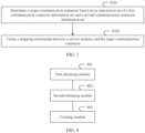
- FIG. 5 is a flowchart of a mapping relationship generation method according to an embodiment of this application. The method may be applied to a processor. As shown in FIG. 5 , the method includes the following steps.
- S501 Obtain information about a mapping relationship between the communication connector on the node and the network domain.
- Step S502 Obtain information about a mapping relationship between a process and the node, where the information about the mapping relationship between the process and the node includes a software component corresponding to the process, and the software component includes at least one port prototype.
- Step S503 Create, based on the information about the mapping relationship between the communication connector on the node and the network domain and the information about the mapping relationship between the process and the node, a service instance for the port prototype used by the process in the network domain, and create a mapping relationship between the service instance and a target communication connector on the node.
- the service instance is created for the port prototype used by the process in the network domain, to create the mapping relationship between the service instance and the target communication connector on the node.
- the mapping relationship can be established between the service instance created in the network domain and the target communication connector without a manual operation, so that a corresponding node can communicate with the service instance, and the mapping relationship does not need to be manually established. This simplifies a configuration procedure and improves configuration efficiency.
- the network domain may be a virtual domain.
- the at least one port prototype may be a plurality of groups of port prototypes, and each group of port prototypes may include a receive port prototype and a send port prototype.
- step S503 For a related example of creating the service instance for the port prototype used by the process in the network domain in step S503, refer to related descriptions in step S204 in FIG. 2 . It should be noted that the creating the service instance for the port prototype used by the process in the network domain may alternatively be associating a service instance with a corresponding port prototype after the service instance is created. For examples of step S501 to step S503, refer to related descriptions in step S205 in FIG. 2 .
- the method is used to configure a communication service in an automotive open system architecture AUTOSAR adaptive platform.
- this method can be applied to a vehicle, so that configuration of communication management CM can be more efficiently implemented on the AUTOSAR adaptive platform, to apply a corresponding communication service.
- FIG. 1 For an architecture of the AUTOSAR adaptive platform, refer to FIG. 1 .
- the method further includes: creating the network domain, and configuring the information about the mapping relationship between the communication connector on the node and the network domain.
- step S201 in FIG. 2 For the process, refer to related descriptions in step S201 in FIG. 2 .
- the method further includes: configuring the mapping relationship between the process and the node, and allocating the corresponding software component to the process.
- an association relationship between the process and the software component can be determined, so that the mapping relationship between the service instance in the network domain and the target communication connector can be automatically created subsequently.
- step S203 in FIG. 2 For the process, refer to related descriptions in step S203 in FIG. 2 .
- the method further includes: configuring a port prototype used by the process to communicate with another process in the network domain.
- step S203 in FIG. 2 For the process, refer to related descriptions in step S203 in FIG. 2 .
- the creating the network domain, and configuring the information about the mapping relationship between the communication connector on the node and the network domain includes: determining an ID of the network domain.
- Creating, based on the information about the mapping relationship between the communication connector on the node and the network domain and the information about the mapping relationship between the process and the node, the service instance for the port prototype used by the process in the network domain, and creating the mapping relationship between the service instance and the target communication connector on the node includes: when a communication protocol of the service instance is a data distribution service DDS, determining that a network domain ID associated with the service instance is the ID.
- the ID of the network domain is determined, so that when the communication protocol is the DDS, the service instance can be associated with the network domain ID without a need of manual setting. This simplifies a configuration process and improves configuration efficiency.
- the ID of the network domain may be the network domain identifier, and the ID may be modified as required.
- step S201 For a related example of creating the network domain, refer to related descriptions in step S201 in FIG. 2 .
- each communication connector is associated with an internet protocol IP address.
- the node can communicate with another configured object through the communication connector.
- FIG. 6 is a flowchart of a mapping relationship generation method according to an embodiment of this application.
- creating, based on information about a mapping relationship between the communication connector on the node and the network domain and information about a mapping relationship between a process and the node, a service instance for a port prototype used by the process in the network domain, and creating a mapping relationship between the service instance and a target communication connector on the node includes the following steps:
- Step S601 Determine, based on the information about the mapping relationship between the communication connector on the node and the network domain, a first communication connector information set corresponding to the network domain, where the first communication connector information set includes at least one communication connector on the node.
- Step S602 Determine, based on information about a mapping relationship between the service instance and the port prototype of the software component, a second communication connector information set corresponding to the port prototype of the software component, where the second communication connector information set includes at least one communication connector on a target node.
- Step S603 Create the mapping relationship between the service instance and the target communication connector based on the first communication connector information set and the second communication connector information set.
- two communication connector information sets are determined, to determine the target communication connector, and the target communication connector does not need to be manually searched for, so that the mapping relationship between the service instance and the target communication connector can be established in a configuration process, and the mapping relationship does not need to be manually established, to implement mapping from the service instance to the node.
- the first communication connector information set may be, for example, the foregoing List A
- the second communication connector information set may be, for example, the foregoing List B.
- FIG. 7 is a flowchart of a mapping relationship generation method according to an embodiment of this application. As shown in FIG. 7 , creating a mapping relationship between the service instance and a target communication connector based on a first communication connector information set and a second communication connector information set includes the following steps:
- Step S701 Determine the target communication connector based on an intersection set of the first communication connector information set and the second communication connector information set.
- Step S702 Create the mapping relationship between the service instance and the target communication connector.
- mapping relationship between the service instance and the target communication connector can be determined without a need of manually searching for the target communication connector corresponding to the service instance, to implement communication between the service instance and the target node. This simplifies a configuration procedure and improves efficiency.
- An intersection set of the first communication connector information set and the second communication connector information set is, for example, an intersection set of the foregoing List A and List B.
- FIG. 8 is a diagram of a structure of a mapping relationship generation apparatus according to an embodiment of this application. As shown in FIG. 8 , the apparatus includes:
- the service instance is created for the port prototype used by the process in the network domain, to create the mapping relationship between the service instance and the target communication connector on the node.
- the mapping relationship can be established between the service instance created in the network domain and the target communication connector without a manual operation, so that a corresponding node can communicate with the service instance, and the mapping relationship does not need to be manually established. This simplifies a configuration procedure and improves configuration efficiency.
- the apparatus is configured to configure a communication service in an automotive open system architecture AUTOSAR adaptive platform.
- this apparatus can be applied to a vehicle, so that configuration of communication management CM can be more efficiently implemented on the AUTOSAR adaptive platform, to apply a corresponding communication service.
- the apparatus further includes: a first configuration module, configured to: create the network domain, and configure the information about the mapping relationship between the communication connector on the node and the network domain.
- the apparatus further includes: a second configuration module, configured to: configure the mapping relationship between the process and the node, and allocate the corresponding software component to the process.
- an association relationship between the process and the software component can be determined, so that the mapping relationship between the service instance in the network domain and the target communication connector can be automatically created subsequently.
- the apparatus further includes a third configuration module, configured to configure the port prototype used by the process to communicate with another process in the network domain.
- the first configuration module includes: determining an ID of the network domain; and the creating module 803 includes: when a communication protocol of the service instance is a data distribution service DDS, determining that a network domain ID associated with the service instance is the ID.
- the ID of the network domain is determined, so that when the communication protocol is the DDS, the service instance can be associated with the network domain ID without a need of manual setting. This simplifies a configuration process and improves configuration efficiency.
- each communication connector is associated with an internet protocol IP address.
- the node can communicate with another configured object through the communication connector.
- the creating module 803 includes: determining, based on the information about the mapping relationship between the communication connector on the node and the network domain, a first communication connector information set corresponding to the network domain, where the first communication connector information set includes at least one communication connector on the node; determining, based on information about a mapping relationship between the service instance and the port prototype of the software component, a second communication connector information set corresponding to the port prototype of the software component, where the second communication connector information set includes at least one communication connector on a target node; and creating the mapping relationship between the service instance and the target communication connector based on the first communication connector information set and the second communication connector information set.
- two communication connector information sets are determined, to determine the target communication connector, and the target communication connector does not need to be manually searched for, so that the mapping relationship between the service instance and the target communication connector can be established in a configuration process, and the mapping relationship does not need to be manually established, to implement mapping from the service instance to the node.
- creating the mapping relationship between the service instance and the target communication connector based on the first communication connector information set and the second communication connector information set includes: determining the target communication connector based on an intersection set of the first communication connector information set and the second communication connector information set; and creating the mapping relationship between the service instance and the target communication connector.
- mapping relationship between the service instance and the target communication connector can be determined without a need of manually searching for the target communication connector corresponding to the service instance, to implement communication between the service instance and the target node. This simplifies a configuration procedure and improves efficiency.
- FIG. 9 is a diagram of a structure of a mapping relationship generation apparatus according to an embodiment of this application.
- the mapping relationship generation apparatus 1100 may be configured to perform the mapping relationship generation method shown in any one of FIG. 2 to FIG. 7 .
- the mapping relationship generation apparatus may be a server, or may be a chip (system) or another part or component that may be disposed inside the server. This is not limited in embodiments of this application.
- the mapping relationship generation apparatus 1100 may include a processor 1101 and a transceiver 1102.
- the mapping relationship generation apparatus 1100 may include a memory 1103.
- the processor 1101 is coupled to the transceiver 1102 and the memory 1103, for example, may be connected through a communication bus.
- mapping relationship generation apparatus 1100 The following describes each part of the mapping relationship generation apparatus 1100 in detail with reference to FIG. 9 .
- the processor 1101 is a control center of the mapping relationship generation apparatus 1100, and may be one processor, or may be a collective name of a plurality of processing elements.
- the processor 1101 may be one or more central processing units (central processing unit, CPU) or an application-specific integrated circuit (application-specific integrated circuit, ASIC), or may be configured as one or more integrated circuits implementing embodiments of this application, for example, one or more microprocessors (digital signal processors, DSPs) or one or more field programmable gate arrays (field programmable gate array, FPGA).
- the processor 1101 may run or execute a software program stored in the memory 1103 and invoke data stored in the memory 1103, to perform various functions of the mapping relationship generation apparatus 1100.
- the processor 1101 may include one or more CPUs, for example, a CPU 0 and a CPU 1 shown in FIG. 9 .
- the mapping relationship generation apparatus 1100 may also include a plurality of processors, for example, a processor 1101 and a processor 1104 shown in FIG. 9 .
- Each of the processors may be a single-core processor (single-core CPU) or a multi-core processor (multi-core CPU).
- the processor herein may be one or more communication devices, circuits, and/or processing cores configured to process data (for example, computer program instructions).
- the transceiver 1102 is configured to communicate with another server.
- the transceiver 1102 may include a receiver and a transmitter (not separately shown in FIG. 9 ).
- the receiver is configured to implement a receiving function
- the transmitter is configured to implement a sending function.
- the transceiver 1102 may be integrated with the processor 1101, or may exist independently, and is coupled to the processor 1101 through an input/output port (not shown in FIG. 9 ) of the mapping relationship generation apparatus 1100. This is not limited in embodiments of this application.
- the memory 1103 may be configured to store a software program for performing the solutions of this application, and the processor 1101 controls execution of the software program.
- the processor 1101 controls execution of the software program.
- the memory 1103 may be a read-only memory (read-only memory, ROM) or another type of static storage communication device that can store static information and instructions, or a random access memory (random access memory, RAM) or another type of dynamic storage communication device that can store information and instructions, or may be an electrically erasable programmable read-only memory (electrically erasable programmable read-only memory, EEPROM), a compact disc read-only memory (compact disc read-only memory, CD-ROM) or another compact disc storage, an optical disc storage (including a compact disc, a laser disc, an optical disc, a digital versatile disc, a Blu-ray optical disc, or the like), a magnetic disk storage medium or another magnetic storage communication device, or any other medium that can be used to carry or store expected program code in a form of instruction or data structure and that can be accessed by a computer.
- ROM read-only memory
- RAM random access memory
- EEPROM electrically erasable programmable read-only memory
- CD-ROM compact disc
- the memory 1103 is not limited thereto. It should be noted that the memory 1103 may be integrated with the processor 1101, or may exist independently, and is coupled to the processor 1101 through an input/output port (not shown in FIG. 9 ) of the mapping relationship generation apparatus 1100. This is not limited in embodiments of this application.
- mapping relationship generation apparatus 1100 shown in FIG. 9 does not constitute a limitation on an implementation of the mapping relationship generation apparatus.
- An actual mapping relationship generation apparatus may include more or fewer parts than those shown in the figure, or combine some parts, or have different part arrangements.
- An embodiment of this application provides a mapping relationship generation apparatus, including a processor and a memory configured to store instructions executable by the processor. When the processor is configured to execute the instructions, the method is implemented.
- An embodiment of this application provides a terminal device, and the terminal device may perform the foregoing methods.
- An embodiment of this application provides a non-volatile computer-readable storage medium, where the non-volatile computer-readable storage medium stores computer program instructions.
- the computer program instructions are executed by a processor, the foregoing methods are implemented.
- An embodiment of this application provides a computer program product, including computer-readable code or a non-volatile computer-readable storage medium carrying a computer-readable code.
- the computer-readable code is run on a processor in an electronic device, the processor in the electronic device performs the foregoing methods.
- the computer-readable storage medium may be a tangible device that may retain and store instructions for use by an instruction execution device.
- the computer-readable storage medium may be, for example, but is not limited to, an electrical storage device, a magnetic storage device, an optical storage device, an electromagnetic storage device, a semiconductor storage device, or any suitable combination thereof.
- the computer-readable storage medium includes: a portable computer disk, a hard disk, a random access memory (Random Access Memory, RAM), a read-only memory (Read-Only Memory, ROM), an erasable programmable read-only memory (Electrically Programmable Read-Only-Memory, EPROM, or flash memory), a static random access memory (Static Random Access Memory, SRAM), a portable compact disc read-only memory (Compact Disc Read-Only Memory, CD-ROM), a digital versatile disc (Digital Video Disc, DVD), a memory stick, a floppy disk, a mechanical coding device, for example, a punching card or a groove protrusion structure that stores instructions, and any suitable combination thereof.
- the computer-readable program instructions or code described herein may be downloaded from the computer-readable storage medium to each computing/processing device, or downloaded to an external computer or an external storage device over a network, for example, the Internet, a local area network, a wide area network, and/or a wireless network.
- the network may include copper transmission cables, optical fiber transmission, wireless transmission, routers, firewalls, switches, gateway computers, and/or edge servers.
- a network adapter card or a network interface in each computing/processing device receives computer-readable program instructions from a network, and forwards the computer-readable program instructions for storage in a computer-readable storage medium in each computing/processing device.
- the computer program instructions used to perform operations in this application may be assembly instructions, instruction set architecture (Instruction Set Architecture, ISA) instructions, machine instructions, machine-related instructions, microcode, firmware instructions, status setting data, or source code or target code written in one or any combination of more programming languages.
- the programming languages include object-oriented programming languages such as Smalltalk and C++, and a conventional procedural programming language like "C" or a similar programming language. All computer-readable program instructions may be executed on a user computer, or some may be executed on a user computer as a standalone software package, or some may be executed on a local computer of a user while some is executed on a remote computer, or all the instructions may be executed on a remote computer or a server.
- the remote computer When the remote computer is involved, the remote computer may be connected to a user computer over any type of network, including a local area network (Local Area Network, LAN) or a wide area network (Wide Area Network, WAN), or may be connected to an external computer (for example, connected by using an Internet service provider over the Internet).
- an electronic circuit for example, a programmable logic circuit, a field programmable gate array (Field-Programmable Gate Array, FPGA), or a programmable logic array (Programmable Logic Array, PLA), is customized by using status information of computer-readable program instructions.
- the electronic circuit may execute the computer-readable program instructions, to implement various aspects of this application.
- These computer-readable program instructions may be provided to a processor of a general-purpose computer, a special-purpose computer, or another programmable data processing apparatus to produce a machine, so that the instructions, when executed by the processor of the computer or the another programmable data processing apparatus, create an apparatus for implementing functions/actions specified in one or more blocks in the flowcharts and/or the block diagrams.
- these computer-readable program instructions may be stored in a computer-readable storage medium. These instructions enable a computer, a programmable data processing apparatus, and/or another device to work in a specific manner. Therefore, the computer-readable medium storing the instructions includes an artifact that includes instructions for implementing various aspects of functions/actions specified in one or more blocks in the flowcharts and/or the block diagrams.
- these computer-readable program instructions may be loaded onto a computer, another programmable data processing apparatus, or another device, so that a series of operation steps are performed on the computer, the another programmable data processing apparatus, or the another device to produce a computer-implemented process. Therefore, the instructions executed on the computer, the another programmable data processing apparatus, or the another device implements functions/actions specified in one or more blocks in the flowcharts and/or the block diagrams.
- each block in the flowcharts or the block diagrams may represent a module, a program segment, or a part of the instructions, where the module, the program segment, or the part of the instructions includes one or more executable instructions for implementing a specified logical function.
- the functions marked in the blocks may also occur in a sequence different from that marked in the accompanying drawings. For example, two consecutive blocks may actually be executed substantially in parallel, and sometimes may be executed in a reverse order, depending on a function involved.
- each block in the block diagrams and/or the flowcharts and a combination of blocks in the block diagrams and/or the flowcharts may be implemented by hardware (for example, a circuit or an ASIC (Application-Specific Integrated Circuit, application-specific integrated circuit)) that performs a corresponding function or action, or may be implemented by a combination of hardware and software, for example, firmware.
- hardware for example, a circuit or an ASIC (Application-Specific Integrated Circuit, application-specific integrated circuit)
- ASIC Application-Specific Integrated Circuit, application-specific integrated circuit
Landscapes
- Engineering & Computer Science (AREA)
- Software Systems (AREA)
- Computer Networks & Wireless Communication (AREA)
- Signal Processing (AREA)
- Theoretical Computer Science (AREA)
- Physics & Mathematics (AREA)
- General Engineering & Computer Science (AREA)
- General Physics & Mathematics (AREA)
- Computer And Data Communications (AREA)
- Stored Programmes (AREA)
Applications Claiming Priority (1)
| Application Number | Priority Date | Filing Date | Title |
|---|---|---|---|
| PCT/CN2021/125308 WO2023065218A1 (zh) | 2021-10-21 | 2021-10-21 | 一种映射关系生成方法、装置和存储介质 |
Publications (2)
| Publication Number | Publication Date |
|---|---|
| EP4407447A1 true EP4407447A1 (de) | 2024-07-31 |
| EP4407447A4 EP4407447A4 (de) | 2024-12-04 |
Family
ID=86058674
Family Applications (1)
| Application Number | Title | Priority Date | Filing Date |
|---|---|---|---|
| EP21960968.2A Pending EP4407447A4 (de) | 2021-10-21 | 2021-10-21 | Verfahren und vorrichtung zur erzeugung von zuordnungsbeziehungen und speichermedium |
Country Status (5)
| Country | Link |
|---|---|
| US (1) | US12549446B2 (de) |
| EP (1) | EP4407447A4 (de) |
| JP (1) | JP7717977B6 (de) |
| CN (1) | CN116324721B (de) |
| WO (1) | WO2023065218A1 (de) |
Families Citing this family (2)
| Publication number | Priority date | Publication date | Assignee | Title |
|---|---|---|---|---|
| CN116684312B (zh) * | 2023-05-31 | 2025-09-16 | 国科础石(重庆)软件有限公司 | 域控制器dds通信网络架构的可视化方法、装置及车辆 |
| CN119902747B (zh) * | 2025-03-28 | 2025-08-15 | 重庆赛力斯凤凰智创科技有限公司 | 软件组件的代理方法、装置、电子设备及存储介质 |
Family Cites Families (16)
| Publication number | Priority date | Publication date | Assignee | Title |
|---|---|---|---|---|
| US8234351B2 (en) * | 2008-07-24 | 2012-07-31 | Go Daddy Operating Company, LLC | Systems for generating and registering enhanced domain names |
| CN102231107B (zh) * | 2011-06-09 | 2013-07-31 | 浙江大学 | 基于autosar的电控单元通信数据格式的自动生成方法 |
| KR20130052330A (ko) * | 2011-11-11 | 2013-05-22 | 한국전자통신연구원 | 오토사 기반 차량 네트워크의 게이트웨이 설정 방법 및 그 장치 |
| US9246773B2 (en) * | 2013-07-30 | 2016-01-26 | Draios Inc. | System, method, and graphical user interface for application topology mapping in hosted computing environments |
| EP3301575B1 (de) * | 2014-05-15 | 2019-07-24 | The MathWorks, Inc. | Verwendung eines elements in einem erste modell zum anrufen eines teils eines zweiten modells |
| KR101628694B1 (ko) * | 2014-12-15 | 2016-06-10 | 현대오트론 주식회사 | 오토사 기반 ecu의 소프트웨어 컴포넌트에 대한 플랫뷰 생성 방법 |
| KR101630729B1 (ko) * | 2015-04-16 | 2016-06-24 | 현대자동차주식회사 | 차량에 최적화된 이더넷 통신 제공 방법 및 시스템 |
| US10798186B2 (en) * | 2016-06-09 | 2020-10-06 | International Business Machines Corporation | Dynamic generation of network routing configuration with service requirements |
| CN106230605B (zh) * | 2016-07-29 | 2019-07-02 | 浙江吉利控股集团有限公司 | 一种基于autosar车载网络的管理系统 |
| EP3652721A1 (de) * | 2017-09-04 | 2020-05-20 | NNG Software Developing and Commercial LLC | Verfahren und vorrichtung zum sammeln und verwenden von sensordaten von einem fahrzeug |
| CN107979493B (zh) * | 2017-11-21 | 2019-10-29 | 平安科技(深圳)有限公司 | 平台即服务paas容器平台的构建方法、服务器及存储介质 |
| CN113196266A (zh) * | 2018-10-02 | 2021-07-30 | 大众汽车股份公司 | 使用车辆的车辆计算单元执行一个或多个车辆应用的方法、车辆计算单元、用于提供用于车辆应用的许可信息清单的方法、用于车辆应用的许可信息清单和计算机程序 |
| KR102275139B1 (ko) * | 2018-12-12 | 2021-07-08 | 현대오트론 주식회사 | Autosar 송신기-수신기 통신을 위한 데이터 매핑 항목 생성 방법 |
| WO2021107179A1 (ko) * | 2019-11-27 | 2021-06-03 | 주식회사 알티스트 | Autosar 기반 응용 소프트웨어의 설정 코드 자동 생성 방법 및 장치 |
| CN111654402B (zh) * | 2020-06-23 | 2023-08-01 | 中国平安财产保险股份有限公司 | 网络拓扑创建方法、装置、设备及存储介质 |
| EP4377817A4 (de) * | 2021-07-26 | 2025-05-28 | Bright Data Ltd. | Emulieren eines webbrowsers in einer dedizierten zwischenbox |
-
2021
- 2021-10-21 JP JP2024523777A patent/JP7717977B6/ja active Active
- 2021-10-21 WO PCT/CN2021/125308 patent/WO2023065218A1/zh not_active Ceased
- 2021-10-21 CN CN202180007810.8A patent/CN116324721B/zh active Active
- 2021-10-21 EP EP21960968.2A patent/EP4407447A4/de active Pending
-
2024
- 2024-04-22 US US18/641,758 patent/US12549446B2/en active Active
Also Published As
| Publication number | Publication date |
|---|---|
| JP2024539191A (ja) | 2024-10-28 |
| EP4407447A4 (de) | 2024-12-04 |
| CN116324721A (zh) | 2023-06-23 |
| US12549446B2 (en) | 2026-02-10 |
| CN116324721B (zh) | 2026-02-17 |
| JP7717977B6 (ja) | 2025-08-21 |
| US20240275688A1 (en) | 2024-08-15 |
| WO2023065218A1 (zh) | 2023-04-27 |
| JP7717977B2 (ja) | 2025-08-04 |
Similar Documents
| Publication | Publication Date | Title |
|---|---|---|
| US12498997B2 (en) | System architecture for implementing DDS communication based on AUTOSAR, communication method, and device | |
| US11895577B2 (en) | Network slice selection method and apparatus | |
| US12549446B2 (en) | Mapping relationship generation method and apparatus, and storage medium | |
| CN104219127B (zh) | 一种虚拟网络实例的创建方法以及设备 | |
| US20140254603A1 (en) | Interoperability for distributed overlay virtual environments | |
| CN114172905B (zh) | 一种集群网络组网的方法、装置、计算机设备及存储介质 | |
| US9614789B2 (en) | Supporting multiple virtual switches on a single host | |
| CN114650223B (zh) | 一种Kubernetes集群的网络配置方法、装置及电子设备 | |
| US11177974B2 (en) | Consistent provision of member node group information on virtual overlay network | |
| US20190173796A1 (en) | Load balancing in data hosting systems | |
| CN111752538B (zh) | 车端场景的生成方法、装置、云端、车端和存储介质 | |
| CN115185647B (zh) | virtio设备直通方法及相关装置 | |
| CN115913937A (zh) | 一种容器多网卡网络配置方法、装置、设备及存储介质 | |
| US11216263B2 (en) | Policy-based automated generation of software-defined storage deployments | |
| CN114070741A (zh) | 一种拓扑图生成方法、系统、设备和存储介质 | |
| US10911371B1 (en) | Policy-based allocation of provider network resources | |
| CN117280320A (zh) | 一种映射关系生成方法、装置和存储介质 | |
| CN113840312B (zh) | 一种5g网络切片业务的配置方法及装置 | |
| US20240364659A1 (en) | Address space recommendation method and apparatus, and related device | |
| CN116431270A (zh) | 配置数据的传输方法及装置、电子设备和可读存储介质 | |
| CN114721766B (zh) | 虚拟机数据存储方法、装置、设备和可读存储介质 | |
| CN121386731B (zh) | 控制器升级方法、电子设备和存储介质 | |
| CN113076128A (zh) | 用于机器人配置的方法、装置、电子设备及存储介质 | |
| CN118802830A (zh) | 分布式系统网络通信的方法及装置、电子设备和存储介质 | |
| CN121098820A (zh) | 智能计算中心云平台的算力服务器网络隧道增强方法及装置 |
Legal Events
| Date | Code | Title | Description |
|---|---|---|---|
| STAA | Information on the status of an ep patent application or granted ep patent |
Free format text: STATUS: THE INTERNATIONAL PUBLICATION HAS BEEN MADE |
|
| PUAI | Public reference made under article 153(3) epc to a published international application that has entered the european phase |
Free format text: ORIGINAL CODE: 0009012 |
|
| STAA | Information on the status of an ep patent application or granted ep patent |
Free format text: STATUS: REQUEST FOR EXAMINATION WAS MADE |
|
| 17P | Request for examination filed |
Effective date: 20240423 |
|
| AK | Designated contracting states |
Kind code of ref document: A1 Designated state(s): AL AT BE BG CH CY CZ DE DK EE ES FI FR GB GR HR HU IE IS IT LI LT LU LV MC MK MT NL NO PL PT RO RS SE SI SK SM TR |
|
| A4 | Supplementary search report drawn up and despatched |
Effective date: 20241105 |
|
| RIC1 | Information provided on ipc code assigned before grant |
Ipc: G06F 9/44 20180101AFI20241029BHEP |
|
| RAP1 | Party data changed (applicant data changed or rights of an application transferred) |
Owner name: SHENZHEN YINWANG INTELLIGENTTECHNOLOGIES CO., LTD. |
|
| DAV | Request for validation of the european patent (deleted) | ||
| DAX | Request for extension of the european patent (deleted) | ||
| STAA | Information on the status of an ep patent application or granted ep patent |
Free format text: STATUS: EXAMINATION IS IN PROGRESS |
|
| 17Q | First examination report despatched |
Effective date: 20251105 |