EP4407397B1 - Remote driving system, remote driving terminal, and method for remote driving - Google Patents
Remote driving system, remote driving terminal, and method for remote driving Download PDFInfo
- Publication number
- EP4407397B1 EP4407397B1 EP23216690.0A EP23216690A EP4407397B1 EP 4407397 B1 EP4407397 B1 EP 4407397B1 EP 23216690 A EP23216690 A EP 23216690A EP 4407397 B1 EP4407397 B1 EP 4407397B1
- Authority
- EP
- European Patent Office
- Prior art keywords
- vehicle
- remote driving
- initial check
- remote
- situation
- Prior art date
- Legal status (The legal status is an assumption and is not a legal conclusion. Google has not performed a legal analysis and makes no representation as to the accuracy of the status listed.)
- Active
Links
Images


Classifications
-
- G—PHYSICS
- G05—CONTROLLING; REGULATING
- G05B—CONTROL OR REGULATING SYSTEMS IN GENERAL; FUNCTIONAL ELEMENTS OF SUCH SYSTEMS; MONITORING OR TESTING ARRANGEMENTS FOR SUCH SYSTEMS OR ELEMENTS
- G05B19/00—Programme-control systems
- G05B19/02—Programme-control systems electric
- G05B19/04—Programme control other than numerical control, i.e. in sequence controllers or logic controllers
- G05B19/042—Programme control other than numerical control, i.e. in sequence controllers or logic controllers using digital processors
- G05B19/0423—Input/output
-
- G—PHYSICS
- G05—CONTROLLING; REGULATING
- G05D—SYSTEMS FOR CONTROLLING OR REGULATING NON-ELECTRIC VARIABLES
- G05D1/00—Control of position, course, altitude or attitude of land, water, air or space vehicles, e.g. using automatic pilots
- G05D1/20—Control system inputs
- G05D1/22—Command input arrangements
- G05D1/221—Remote-control arrangements
- G05D1/227—Handing over between remote control and on-board control; Handing over between remote control arrangements
-
- G—PHYSICS
- G05—CONTROLLING; REGULATING
- G05D—SYSTEMS FOR CONTROLLING OR REGULATING NON-ELECTRIC VARIABLES
- G05D1/00—Control of position, course, altitude or attitude of land, water, air or space vehicles, e.g. using automatic pilots
- G05D1/20—Control system inputs
- G05D1/22—Command input arrangements
- G05D1/221—Remote-control arrangements
- G05D1/225—Remote-control arrangements operated by off-board computers
-
- G—PHYSICS
- G05—CONTROLLING; REGULATING
- G05D—SYSTEMS FOR CONTROLLING OR REGULATING NON-ELECTRIC VARIABLES
- G05D1/00—Control of position, course, altitude or attitude of land, water, air or space vehicles, e.g. using automatic pilots
- G05D1/20—Control system inputs
- G05D1/22—Command input arrangements
- G05D1/221—Remote-control arrangements
- G05D1/222—Remote-control arrangements operated by humans
- G05D1/224—Output arrangements on the remote controller, e.g. displays, haptics or speakers
- G05D1/2244—Optic
- G05D1/2247—Optic providing the operator with simple or augmented images from one or more cameras
-
- G—PHYSICS
- G05—CONTROLLING; REGULATING
- G05D—SYSTEMS FOR CONTROLLING OR REGULATING NON-ELECTRIC VARIABLES
- G05D1/00—Control of position, course, altitude or attitude of land, water, air or space vehicles, e.g. using automatic pilots
- G05D1/20—Control system inputs
- G05D1/24—Arrangements for determining position or orientation
- G05D1/243—Means capturing signals occurring naturally from the environment, e.g. ambient optical, acoustic, gravitational or magnetic signals
-
- G—PHYSICS
- G05—CONTROLLING; REGULATING
- G05D—SYSTEMS FOR CONTROLLING OR REGULATING NON-ELECTRIC VARIABLES
- G05D1/00—Control of position, course, altitude or attitude of land, water, air or space vehicles, e.g. using automatic pilots
- G05D1/60—Intended control result
- G05D1/617—Safety or protection, e.g. defining protection zones around obstacles or avoiding hazards
-
- G—PHYSICS
- G05—CONTROLLING; REGULATING
- G05D—SYSTEMS FOR CONTROLLING OR REGULATING NON-ELECTRIC VARIABLES
- G05D1/00—Control of position, course, altitude or attitude of land, water, air or space vehicles, e.g. using automatic pilots
- G05D1/80—Arrangements for reacting to or preventing system or operator failure
- G05D1/86—Monitoring the performance of the system, e.g. alarm or diagnosis modules
-
- G—PHYSICS
- G05—CONTROLLING; REGULATING
- G05B—CONTROL OR REGULATING SYSTEMS IN GENERAL; FUNCTIONAL ELEMENTS OF SUCH SYSTEMS; MONITORING OR TESTING ARRANGEMENTS FOR SUCH SYSTEMS OR ELEMENTS
- G05B2219/00—Program-control systems
- G05B2219/20—Pc systems
- G05B2219/23—Pc programming
- G05B2219/23051—Remote control, enter program remote, detachable programmer
-
- G—PHYSICS
- G05—CONTROLLING; REGULATING
- G05D—SYSTEMS FOR CONTROLLING OR REGULATING NON-ELECTRIC VARIABLES
- G05D2107/00—Specific environments of the controlled vehicles
- G05D2107/10—Outdoor regulated spaces
- G05D2107/13—Spaces reserved for vehicle traffic, e.g. roads, regulated airspace or regulated waters
-
- G—PHYSICS
- G05—CONTROLLING; REGULATING
- G05D—SYSTEMS FOR CONTROLLING OR REGULATING NON-ELECTRIC VARIABLES
- G05D2109/00—Types of controlled vehicles
- G05D2109/10—Land vehicles
-
- G—PHYSICS
- G05—CONTROLLING; REGULATING
- G05D—SYSTEMS FOR CONTROLLING OR REGULATING NON-ELECTRIC VARIABLES
- G05D2111/00—Details of signals used for control of position, course, altitude or attitude of land, water, air or space vehicles
- G05D2111/10—Optical signals
Definitions
- the present disclosure relates to a technique for performing remote driving of a vehicle.
- Patent Literature 1 discloses a vehicle control device. When a transition from one driving state to another driving state is scheduled, the vehicle control device performs notification of information relating to the transition of the driving state to an occupant and to other vehicles.
- the driving state includes manual driving, autonomous driving, and remote driving.
- US 2021/089024 A1 discloses a method for controlling a motor vehicle remotely.
- Patent Literature 1 Japanese Laid-Open Patent Application No. JP-2021-018486
- a system for remotely driving a vehicle based on an operation amount input to a remote driving terminal by a remote operator is known.
- Such a system is sometimes referred to as a remote driving system.
- the remote driving system starts remote driving when a situation in which the vehicle requires the remote driving occurs. However, at this time, the remote driving system does not immediately start the remote driving.
- the remote driving system first performs an initial check for checking that the remote driving can be started.
- the remote driving system starts the remote driving only after obtaining a good result of the initial check. Therefore, in order to smoothly start the remote driving, it is required to finish the initial check early.
- An object of the present disclosure is to provide a technique for finishing an initial check early and starting remote driving smoothly in a remote driving system.
- the first aspect of the present disclosure relates to a remote driving system that performs remote driving of a vehicle based on an operation amount input to a remote driving terminal.
- the remote driving system includes at least one processor.
- the at least one processor detects a first situation in which the remote driving of the vehicle is required.
- the at least one processor acquires an urgency level of the first situation.
- the at least one processor performs an initial check for checking that the remote driving can be started at the remote driving terminal when the first situation is detected.
- the at least one processor omits a part of the initial check according to the urgency level.
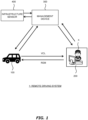
- Fig. 1 is a schematic diagram illustrating a configuration example of a remote driving system 1 according to the present embodiment.
- the remote driving system 1 includes a vehicle 100, a remote driving terminal 200, and a management device 300.
- the vehicle 100, the remote driving terminal 200, and the management device 300 can communicate with each other via a communication network.
- the vehicle 100 receives the remote driving information REM transmitted from the remote driving terminal 200.
- the vehicle 100 controls traveling of the vehicle in accordance with the received remote driving information REM. In this way, the remote driving of the vehicle 100 is performed.
- the remote driving of the vehicle 100 is started by the remote driving system 1 when the first situation is detected. However, the remote driving is not started immediately after the first situation is detected. If the first situation is detected, the remote driving system 1 first performs an "initial check" for checking that the remote driving can be started. Then, the remote driving system 1 starts the remote driving when it is determined that the remote driving can be started in accordance with a result of the initial check.
- "communication establishment check” is performed for checking that communication between the vehicle 100 and the remote driving terminal 200 is normally established. More specifically, in the communication establishment check, it is checked that the vehicle 100 and the remote driving terminal 200 assigned to this vehicle 100 are normally connected to each other and are in a communicable state. For example, the remote driving terminal 200 transmits a test signal for the communication establishment check to the vehicle 100. The test signal may be a ping. Then, when the remote driving terminal 200 normally receives a response signal transmitted from the vehicle 100 in response to the test signal, it is determined that the communication is normally established. When it is determined that the communication is normally established, it means that necessary information can be accurately transmitted and received between the vehicle 100 and the remote driving terminal 200.
- the steering position alignment means bringing a steering angle of the steering operation member of the remote driving terminal 200 in line with a steering angle of the vehicle 100.
- the steering angle of the vehicle 100 is a steering angle of a steering wheel of the vehicle 100.
- the steering angle of the vehicle 100 may be calculated from a steering angle of the wheels of the vehicle 100.
- Information about the steering angle of the steering wheel or the steering angle of the wheels of the vehicle 100 can be acquired from the vehicle information VCL transmitted from the vehicle 100 to the remote driving terminal 200.
- the steering angle of the steering operation member of the remote driving terminal 200 is detected by the sensor installed in the steering operation member.
- the steering position alignment means adjusting the steering angle of the steering operation member such that the two traveling trajectories 221 and 222 come into line with each other.
- the steering position alignment is performed by the remote operator X controlling the steering operation member such that the traveling trajectory 221 and the traveling trajectory 222 come into line with each other.
- the remote operator X uses a button or the like of the remote operation member 230 to input information indicating that the two trajectories come into contact with each other.
- an operation check is performed.
- the operation check is for checking that the operation amount of the remote operator X transmitted to the vehicle 100 as the remote driving information REM is reflected in the operation of the actuator 130, that is, the actuator 130 operates in response to the operation amount of the remote operator X.
- the operation check includes an operation check for the brake and an operation check for the steering. Order of performing the operation check for the brake and performing the operation check for the steering is not limited.
- the remote driving system 1 when detecting the first situation, in which the remote driving of the vehicle 100 is required, acquires an " urgency level," which is an index indicating a degree of urgency of the first situation. Then, the remote driving system 1 omits a part of the initial check according to the urgency level. By omitting a part of the initial check, the time necessary for the initial check can be shortened, and the remote driving can be started early. That is, it is possible to smoothly start the remote driving in consideration of the urgency level of the situation in which the remote driving of the vehicle 100 is required.
- Omitting a part of the initial check means omitting any one or more steps from among the plurality of steps included in the initial check. Which process is omitted is determined based on the urgency level and "priority".
- Fig. 8 is a priority map showing the priority of omission.
- the priority map is stored in any of the memory 170 of the vehicle 100, the memory 270 of the remote driving terminal 200, and the memory 370 of the management device 300.
- a process having high priority is preferentially omitted in accordance with a priority map like this.
- the communication establishment check is a process that is most important to be performed in advance when the remote driving of the vehicle 100 is started. If the communication between the vehicle 100 and the remote driving terminal 200 is not normally established, the vehicle information VCL and the remote driving information REM cannot be transmitted and received between the vehicle 100 and the remote driving terminal 200. If the vehicle information VCL is not normally transmitted from the vehicle 100 to the remote driving terminal 200, the remote operator X cannot obtain information necessary for the remote driving. Further, if the remote driving information REM is not normally transmitted from the remote driving terminal 200 to the vehicle 100, the remote driving cannot be performed in the first place. Therefore, the priority of omission of the communication establishment check is set to be the lowest.
- the steering position alignment is not necessarily required to be performed before the remote driving is started.
- the remote operator X can start to operate the steering operation member with the steering angle of the steering operation member being in line with the steering angle of the wheels, and thus can easily get the feel of the steering.
- the remote operator X can operate the steering operation member to input the operation amount. Therefore, the priority of omission of the steering position alignment is set to be the highest.
- the priority of omission of the operation check for the steering is set to be higher than the priority omission of the operation check for the brake.
- the operation check for the brake is more important to be performed in advance than that for the steering. This is because, it is considered that if a situation in which the vehicle 100 needs to avoid danger urgently, the remote operator X operates the brake first. Therefore, the priority of omission of the operation check for the steering is set to be higher than that for the brake.
- an amount of omission of the initial check is determined based on the urgency level.
- the remote driving is required to be started earlier as the urgency level becomes higher. Therefore, the amount of omission of the initial check is made larger as the urgency level becomes higher, and the amount of omission of the initial check is made smaller as the urgency level becomes lower.
- the urgency level may be calculated based on the deviation amount of the position of the vehicle 100 from the target path. In this case, the urgency level is calculated to be higher as the deviation amount becomes larger.
- the urgency level may be calculated based on a situation that the vehicle 100 is in at the time of detection of the first situation.
- the urgency level may be calculated as follows. When the vehicle 100 is in a dangerous situation, the urgency level is calculated to be the highest. When the vehicle is not in the dangerous situation but in a situation where the vehicle may interfere with other traffic participants, the urgency level is calculated to be the next highest. In the other cases, the urgency level is calculated to be still lower.
- the dangerous situation is, for example, a situation in which it is raining heavily and the vehicle 100 is passing an underpass or is stopped in an underpass.
- the dangerous situation is a situation where an accident such as a fire occurs at a place where the vehicle 100 is located or in the vicinity thereof or a situation where the vehicle 100 is in a railroad crossing and alarm sound is ringing.
- Examples of a situation where the vehicle may interfere with other traffic participants includes a situation where an emergency vehicle is approaching the vehicle 100.
- the remote driving system 1 can determine a situation like these based on information acquired from the infrastructure sensor 400 or the sensor group 120. For example, the remote driving system 1 can detect a situation where it rains heavily based on information acquired from the rainfall sensor of the sensor group 120 or the rainfall sensor of the infrastructure sensor 400. As another example, the remote driving system 1 can determine that the vehicle 100 is passing or stopping in the underpass or the situation around the vehicle 100 including whether the emergency vehicle is approaching based on information acquired from the in-vehicle camera or the infrastructure camera.
- the urgency level in a case where the vehicle 100 is stopped or is expected to stop when the first situation is detected, the urgency level may be calculated based on a stop position of the vehicle 100.
- the urgency level may be calculated as follows. When the stop position of the vehicle 100 is in the dangerous area, the urgency level is calculated to be the highest. When the stop position of the vehicle 100 is not in the dangerous area but in an area where the vehicle 100 may interfere with other traffic participants, the urgency level is calculated to be the next highest. In the other cases, the urgency level is calculated to be still lower.
- the dangerous area mentioned here is a place where the vehicle 100 may be in danger if the vehicle 100 continues to stop in the area.
- Examples of the dangerous area include an area on a track of a streetcar, an area in the railroad crossing, and a stopping prohibited area.
- Examples of the stopping prohibited area include an area in front of a fire station.
- Examples of the area where the vehicle 100 may interfere with other traffic participants include the vicinity of an intersection and a road with a heavy traffic.
- the remote driving system 1 can determine the stop position of the vehicle 100 based on information detected by the infrastructure sensor 400 or the sensor group 120. For example, the remote driving system 1 can determine that the vehicle 100 is stopped in the railroad crossing by acquiring the image captured by the in-vehicle camera or the infrastructure camera. Alternatively, the stop position of the vehicle 100 may be acquired by comparing the map information indicating a location of the railroad, the railroad crossing, or the like and the position information acquired from the GNSS sensor of the sensor group 120. The map information is stored in any of the memory 170 of the vehicle 100, the memory 270 of the remote driving terminal 200, and the memory 370 of the management device 300. The remote driving system 1 may determine whether the traffic is heavy at the stop position of the vehicle 100 based on road traffic information which the management device 300 has, road traffic information acquired from an external server, or the like.
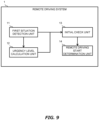
- Fig. 9 is a block diagram illustrating an example of a functional configuration of the remote driving system 1.
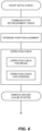
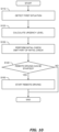
- Fig. 10 is a flowchart illustrating an example of processing executed by the remote driving system 1.
- the remote driving system 1 includes a first situation detection unit 11, an urgency level calculation unit 12, an initial check unit 13, and a remote driving start determination unit 14 as functional blocks.
- the urgency level calculation unit 12 calculates the urgency level.
- a processing entity which realizes the urgency level calculation unit 12 may be the processor 160, the processor 260, or the processor 360. Alternatively, the urgency level calculation unit 12 may be realized by cooperation of these processors.
- the processor 160 of the vehicle 100 acquires information about the stop position of the vehicle 100 from the GNSS sensor of the sensor group 120.
- the processor 160 also acquires information indicating a location of the dangerous area from the map information stored in the memory 170. Then, the processor 160 calculates the urgency level based on whether the stop position of vehicle 100 is included in the dangerous area or not.
- the processor 360 of the management device 300 may detect the traveling position of the vehicle 100 based on the infrastructure information acquired from the infrastructure sensor 400. Then, the processor 160 or the processor 360 may calculate the urgency level by comparing the traveling position of the vehicle 100 with the target path.
- the urgency level calculation unit 12 transmits information about the calculated urgency level to the initial check unit 13, and then the processing proceeds to Step S130.
- Step S130 the initial check unit 13 performs the initial check.
- the initial check unit 13 is realized by the processor 260 of the remote driving terminal 200.
- the initial check unit 13 omits a part of the initial check in accordance with the urgency level calculated by the urgency level calculation unit 12. Which step (steps) of the initial check is omitted is determined in accordance with to the urgency level and the priority as described above.
- the initial check unit 13 transmits the result of the initial check to the remote driving start determination unit 14, and then the processing proceeds to Step S140.
- Step S140 if the result of the initial check indicates that the remote driving can be started (Step S140; Yes), the processing proceeds to Step S150.
- Step S150 the remote driving start determination unit 14 starts the remote driving of the vehicle 100.
- the remote driving is started at time T3 after the initial check is finished.
- the remote driving is started at time T2, which is the time earlier than time T3.
- a part of the initial check is omitted in accordance with the urgency level, and thus the initial check can be finished early.
- the time from when the remote driving is required to when the remote driving is started can be shortened.
- the urgency level is particularly high
- the time until the remote driving is started can be further shortened by increasing the amount of omission.
- which step of the initial check is omitted is determined according to the priority. Since the priority of a particularly important process is set to be low, this process is performed without being omitted, and it is possible to prevent a failure from being found after the remote driving is started. In this way, the remote driving can be started smoothly.
- the autonomous driving vehicle autonomously travels in a factory ground.
- the autonomous driving vehicle assembled in an assembly factory travels from the assembly factory to a yard by autonomously traveling along a predetermined route.
- One or more infrastructure cameras are installed on a road from the assembly factory to the yard. By using the infrastructure camera, the management device 300 of the remote driving system 1 can remotely monitor the autonomous driving vehicle that is autonomously traveling.
- the priority of omission of the side camera check is set to be higher than the priority of omission of the front camera check. It is considered that the remote operator X acquires more information from the image captured by the front camera than from that by the side camera during the remote driving. Therefore, the priority of omission of the side camera check is set to be higher. Similarly, in a case where the in-vehicle cameras include a camera other than the side camera, the priority of omission of the camera check for the camera other than the front camera is set to be higher than the priority of omission of the front camera check.
- Fig. 13 is a block diagram illustrating an example of a functional configuration of the remote driving system 1 according to the second modification.
- the remote driving system 1 includes a vehicle speed limitation unit 15 as a functional block.
- the vehicle speed limitation unit 15 may be included in the vehicle 100.
- the control device 150 controls the vehicle 100 such that the vehicle speed does not exceed the upper limit.
- the vehicle speed limitation unit 15 may be included in the remote driving terminal 200.
- the vehicle speed limitation unit 15 limits the input of the remote operator X such that the vehicle speed does not exceed the upper limit.
- the vehicle speed limitation unit 15 may be included in the management device 300. In this case, information about the vehicle speed set by the management device is transmitted to the vehicle 100 or the remote driving terminal 200.
Landscapes
- Engineering & Computer Science (AREA)
- Physics & Mathematics (AREA)
- General Physics & Mathematics (AREA)
- Automation & Control Theory (AREA)
- Aviation & Aerospace Engineering (AREA)
- Radar, Positioning & Navigation (AREA)
- Remote Sensing (AREA)
- Traffic Control Systems (AREA)
- Control Of Position, Course, Altitude, Or Attitude Of Moving Bodies (AREA)
- Control Of Driving Devices And Active Controlling Of Vehicle (AREA)
Description
- The present disclosure relates to a technique for performing remote driving of a vehicle.
-
Patent Literature 1 discloses a vehicle control device. When a transition from one driving state to another driving state is scheduled, the vehicle control device performs notification of information relating to the transition of the driving state to an occupant and to other vehicles. The driving state includes manual driving, autonomous driving, and remote driving.
US 2021/089024 A1 discloses a method for controlling a motor vehicle remotely. - Patent Literature 1: Japanese Laid-Open Patent Application No.
JP-2021-018486 - A system for remotely driving a vehicle based on an operation amount input to a remote driving terminal by a remote operator is known. Such a system is sometimes referred to as a remote driving system. The remote driving system starts remote driving when a situation in which the vehicle requires the remote driving occurs. However, at this time, the remote driving system does not immediately start the remote driving. For starting the remote driving, the remote driving system first performs an initial check for checking that the remote driving can be started. The remote driving system starts the remote driving only after obtaining a good result of the initial check. Therefore, in order to smoothly start the remote driving, it is required to finish the initial check early.
- An object of the present disclosure is to provide a technique for finishing an initial check early and starting remote driving smoothly in a remote driving system.
- The first aspect of the present disclosure relates to a remote driving system that performs remote driving of a vehicle based on an operation amount input to a remote driving terminal. The remote driving system includes at least one processor. The at least one processor detects a first situation in which the remote driving of the vehicle is required. The at least one processor acquires an urgency level of the first situation. The at least one processor performs an initial check for checking that the remote driving can be started at the remote driving terminal when the first situation is detected. The at least one processor omits a part of the initial check according to the urgency level. The initial check at the remote driving terminal includes: a first initial check that checks communication establishment with the vehicle; a second initial check that checks that a brake actuator of the vehicle operates in response to the operation amount of a brake transmitted to the vehicle; a third initial check that checks that a steering actuator of the vehicle operates in response to the operation amount of a steering; and a fourth initial check that performs steering position alignment between the vehicle and the remote driving terminal.
- The second aspect of the present disclosure relates to a remote driving terminal that performs remote driving of a vehicle based on an operation amount input by a remote operator. The remote driving terminal includes at least one processor. The at least one processor acquires information indicating that a first situation in which the remote driving of the vehicle is required is detected. The at least one processor acquires an urgency level of the first situation. The at least one processor performs an initial check for checking that the remote driving terminal can start the remote driving when the first situation is detected. The at least one processor omits a part of the initial check according to the urgency level. The initial check at the remote driving terminal includes: a first initial check that checks communication establishment with the vehicle; a second initial check that checks that a brake actuator of the vehicle operates in response to the operation amount of a brake transmitted to the vehicle; a third initial check that checks that a steering actuator of the vehicle operates in response to the operation amount of a steering; and a fourth initial check that performs steering position alignment between the vehicle and the remote driving terminal.
- The third aspect of the present disclosure relates to a method for performing remote driving of a vehicle based on an operation amount input into a remote driving terminal. The method includes detecting a first situation in which the remote driving of the vehicle is required, acquiring an urgency level of the first situation, performing an initial check for checking that the remote driving can be started at the remote driving terminal when the first situation is detected, and omitting a part of the initial check according to the urgency level. The initial check at the remote driving terminal includes: a first initial check that checks communication establishment with the vehicle; a second initial check that checks that a brake actuator of the vehicle operates in response to the operation amount of a brake transmitted to the vehicle; a third initial check that checks that a steering actuator of the vehicle operates in response to the operation amount of a steering; and a fourth initial check that performs steering position alignment between the vehicle and the remote driving terminal.
- According to the present disclosure, an urgency level of a situation in which remote driving of a vehicle is required is acquired. Then, a part of an initial check is omitted according to the urgency level. By omitting a part of the initial check, it is possible to finish the initial check early and to smoothly start the remote driving. That is, according to the present disclosure, it is possible to smoothly start the remote driving with the urgency level of the situation in which the remote driving of the vehicle is required taken into consideration.
-
-
Fig. 1 is a schematic diagram illustrating a configuration example of a remote driving system according to a present embodiment. -
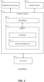
Fig. 2 is a block diagram illustrating a configuration example of a vehicle according to the present embodiment. -
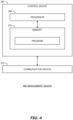
Fig. 3 is a block diagram illustrating a configuration example of a remote driving terminal according to the present embodiment. -
Fig. 4 is a block diagram illustrating a configuration example of a management device according to the present embodiment. -
Fig. 5 is a schematic diagram for explaining deviation from a target path. -
Fig. 6 is a diagram for explaining a specific example of an initial check. -
Fig. 7 is a schematic diagram illustrating steering position alignment. -
Fig. 8 is a diagram illustrating a priority map according to the present embodiment. -
Fig. 9 is a block diagram illustrating an example of a functional configuration of the remote driving system according to the present embodiment. -
Fig. 10 is a flowchart illustrating an example of processing executed by the remote driving system according to the present embodiment. -
Fig. 11 is a time chart for explaining an effect of the processing executed by the remote driving system according to the present embodiment. -
Fig. 12 is a diagram for explaining the first modification. -
Fig. 13 is a block diagram illustrating an example of a functional configuration of the remote driving system according to the second modification. - Embodiments of the present disclosure will be described with reference to the accompanying drawings.
-
Fig. 1 is a schematic diagram illustrating a configuration example of aremote driving system 1 according to the present embodiment. Theremote driving system 1 includes avehicle 100, aremote driving terminal 200, and amanagement device 300. Thevehicle 100, theremote driving terminal 200, and themanagement device 300 can communicate with each other via a communication network. - The
vehicle 100 is a vehicle to be remotely driven by a remote operator X. Thevehicle 100 may be an autonomous driving vehicle. Theremote driving terminal 200 is a terminal device operated by the remote operator X when the remote operator X performs remote driving of thevehicle 100. Theremote driving terminal 200 may be referred to as a remote cockpit. Themanagement device 300 manages theremote driving system 1. Typically, themanagement device 300 is a management server on a cloud. Themanagement device 300 may be composed of a plurality of servers which performs distributed processes. - In addition, the
remote driving system 1 may include aninfrastructure sensor 400. Theinfrastructure sensor 400 includes an infrastructure camera. Theinfrastructure sensor 400 may further include a rainfall sensor or the like. Theinfrastructure sensor 400 is installed in an area where thevehicle 100 travels. Theinfrastructure sensor 400 and themanagement device 300 can communicate with each other via a communication network. Theinfrastructure sensor 400 may communicate with thevehicle 100 and theremote driving terminal 200 directly or via themanagement device 300. -
Figs. 2 to 4 are block diagrams illustrating configuration examples of thevehicle 100, theremote driving terminal 200, and themanagement device 300, respectively. -
Fig. 2 illustrates a configuration example of thevehicle 100. Thevehicle 100 includes acommunication device 110, asensor group 120, anactuator 130, and acontrol device 150. In this example, thevehicle 100 is equipped with an autonomous driving system and can perform autonomous driving. - The
communication device 110 communicates with the outside of thevehicle 100. The communication destination of thecommunication device 110 includes theremote driving terminal 200 and themanagement device 300. - The
sensor group 120 includes a recognition sensor, a vehicle state sensor, a position sensor, and the like. The recognition sensor recognizes (detects) a situation around thevehicle 100. Examples of the recognition sensor include an in-vehicle camera, a laser imaging detection and ranging (LIDAR), and a radar. The vehicle state sensor detects a state of thevehicle 100. The vehicle state sensor includes a speed sensor, an acceleration sensor, a yaw rate sensor, a steering angle sensor, a brake hydraulic pressure sensor, and the like. The position sensor detects a position and a direction of thevehicle 100. The position sensor includes, for example, a global navigation satellite system (GNSS) sensor. Thesensor group 120 may further include a rainfall sensor. - The
actuator 130 includes a steering actuator, a drive actuator, and a brake actuator. The steering actuator steers the wheels. The steering actuator includes, for example, an electric power steering (EPS). The drive actuator is a power source which generates a driving force. Examples of the drive actuator include an engine, an electric motor, and an in-wheel motor. The brake actuator generates a braking force. For example, the brake actuator controls the brake hydraulic pressure to operate the brake. - The
control device 150 is a computer which controls thevehicle 100. Thecontrol device 150 includes at least one processor (processing circuitry) 160 (hereinafter, simply referred to as a processor 160) and at least one memory 170 (hereinafter, simply referred to as a memory 170). Theprocessor 160 executes various processes. For example, theprocessor 160 includes a central processing unit (CPU). Thememory 170 stores various programs and various kinds of information necessary for processing by theprocessor 160. By theprocessor 160 executing the program stored in thememory 170, the function of thecontrol device 150 is realized. Examples of thememory 170 include a volatile memory, a non-volatile memory, a hard disk drive (HDD), and a solid state drive (SSD). Thecontrol device 150 may include at least one electronic control unit (ECU). - The
control device 150 controls theactuator 130 to control traveling of thevehicle 100. Thecontrol device 150 acquires vehicle information VCL from thesensor group 120. The vehicle information VCL includes recognition sensor information showing a result of recognition by the recognition sensor, vehicle state information acquired from the vehicle state sensor, and position information acquired from the position sensor. The recognition sensor information includes an image captured by the in-vehicle camera. The vehicle state information includes speed information, acceleration information, steering angle information, brake hydraulic pressure information, and the like. They are acquired from the speed sensor, the acceleration sensor, the steering angle sensor, the brake hydraulic pressure sensor, and the like. The vehicle information VCL may further include highly accurate position information acquired by localization. Thecontrol device 150 can acquire highly accurate position information by performing the localization using map information and the recognition sensor information stored in thememory 170. The vehicle information VCL acquired by thecontrol device 150 can be used for the autonomous driving or the remote driving of thevehicle 100. - For example, the
control device 150 controls the autonomous driving of thevehicle 100 based on the vehicle information VCL. More specifically, thecontrol device 150 generates a travel plan of thevehicle 100 based on the vehicle information VCL. Further, thecontrol device 150 generates a target path necessary for thevehicle 100 to travel in accordance with the travel plan based on the vehicle information VCL. The target path is a gathering of target positions of thevehicle 100. The target path may be set to extend along the center of the lane. Then, thecontrol device 150 controls traveling of thevehicle 100 such that thevehicle 100 follows the target path. - The
control device 150 can communicate via thecommunication device 110 and transmit the vehicle information VCL to theremote driving terminal 200 and themanagement device 300. At least while the remote driving of thevehicle 100 is performed, the vehicle information VCL is transmitted to theremote driving terminal 200. The vehicle information VCL transmitted to theremote driving terminal 200 is referred to by the remote operator X, and the remote driving is performed. -
Fig. 3 illustrates a configuration example of theremote driving terminal 200. Theremote driving terminal 200 includes acommunication device 210, anoutput device 220, aremote operation member 230, and acontrol device 250. - The
communication device 210 communicates with thevehicle 100 and themanagement device 300. - The
output device 220 outputs various kinds of information and presents the information to the remote operator X. For example, theoutput device 220 includes a display device. The display device displays various kinds of information to the remote operator X. As another example, theoutput device 220 may include a speaker. - The
remote operation member 230 is a member operated by the remote operator X when the remote operator X remotely drives thevehicle 100. Theremote operation member 230 includes, for example, a steering operation member, an accelerator pedal, a brake pedal, a direction indicator, and the like. The steering operation member is, for example, a steering wheel. Theremote operation member 230 may include a touch panel, a button, or the like. An operation amount input by the remote operator X during the remote driving of thevehicle 100 is detected by a sensor installed in theremote operation member 230. - The
control device 250 controls theremote driving terminal 200. Thecontrol device 250 includes at least one processor (processing circuitry) 260 (hereinafter, simply referred to as a processor 260) and at least one memory 270 (hereinafter, simply referred to as a memory 270). Theprocessor 260 executes various processes. For example, theprocessor 260 includes a CPU. Thememory 270 stores various programs and various kinds of information necessary for processing by theprocessor 260. By theprocessor 260 executing the program stored in thememory 270, the function of thecontrol device 250 is realized. Examples of thememory 270 include a volatile memory, a non-volatile memory, an HDD, and an SSD. - The
control device 250 communicates with thevehicle 100 via thecommunication device 210. Thecontrol device 250 receives the vehicle information VCL transmitted from thevehicle 100. Thecontrol device 250 presents the vehicle information VCL to the remote operator X by displaying the vehicle information VCL including the image on the display device. The remote operator X can recognize the state of thevehicle 100, the situation around thevehicle 100, or the like based on the vehicle information VCL displayed on the display device. - In addition, the
control device 250 may acquire infrastructure information detected by theinfrastructure sensor 400 directly or via themanagement device 300. The infrastructure information acquired by thecontrol device 250 may include, for example, an image acquired by the infrastructure camera capturing thevehicle 100 and the surroundings thereof. The acquired infrastructure information is displayed on the display device. The remote operator X may recognize the state of thevehicle 100, the situation around thevehicle 100, or the like by referring to the infrastructure information. By presenting the image captured by the infrastructure camera to the remote operator X in addition to the image captured by the in-vehicle camera, accuracy of the remote driving or usability for the remote operator X can be improved. - The
control device 250 generates remote driving information REM based on the operation amount input by the remote operator X. The remote driving information REM is information for controlling thevehicle 100 by the remote driving. The remote driving information REM includes the operation amount of theremote operation member 230 input by the remote operator X. Thecontrol device 250 transmits the remote driving information REM to thevehicle 100 as necessary. -
Fig. 4 illustrates a configuration example of themanagement device 300. Themanagement device 300 includes acommunication device 310 and acontrol device 350. - The
communication device 310 communicates with thevehicle 100, theremote driving terminal 200, and theinfrastructure sensor 400. - The
control device 350 controls themanagement device 300. Thecontrol device 350 includes at least one processor (processing circuitry) 360 (hereinafter, simply referred to as a processor 360) and at least one memory 370 (hereinafter, simply referred to as a memory 370). Theprocessor 360 executes various processes. For example, theprocessor 360 includes a CPU. Thememory 370 stores various programs and various kinds of information necessary for processing by theprocessor 360. By theprocessor 360 executing the program stored in thememory 370, the function of thecontrol device 350 is realized. Examples of thememory 370 include a volatile memory, a non-volatile memory, an HDD, and an SSD. - The
control device 350 communicates with thevehicle 100 and theremote driving terminal 200 via thecommunication device 310. In addition, thecontrol device 350 communicates with theinfrastructure sensor 400 via thecommunication device 310 as necessary to acquire the infrastructure information. The infrastructure information which thecontrol device 350 acquires from theinfrastructure sensor 400 includes the image captured by the infrastructure camera. - The
remote driving system 1 performs the remote driving of thevehicle 100 based on the operation amount input into theremote driving terminal 200 by the remote operator X. When theremote driving system 1 detects a "first situation", the remote driving of thevehicle 100 is started. The first situation is a situation in which the remote driving of thevehicle 100 is required. The first situation may be detected by thevehicle 100 itself or may be detected by themanagement device 300. - The first situation may be, for example, a situation in which a remote driving request (Request for Operation, RFO) is transmitted from the
vehicle 100 to themanagement device 300. For example, when the autonomous driving system of thevehicle 100 determines that it is difficult to continue the autonomous driving, the remote driving request is transmitted from thevehicle 100 to themanagement device 300. The remote driving request may be transmitted from thevehicle 100 while thevehicle 100 is traveling or may be transmitted while thevehicle 100 is stopped. - Alternatively, the
remote driving system 1 may detect the first situation based on the infrastructure information acquired from theinfrastructure sensor 400. For example, when the rainfall sensor of theinfrastructure sensor 400 shows that average rainfall in a place where thevehicle 100 travels is larger than a threshold value, it is presumed that it is difficult for thevehicle 100 to continue the autonomous driving. As another example, when an abnormal state of thevehicle 100 is detected from the image captured by the infrastructure camera of theinfrastructure sensor 400, it is presumed that thevehicle 100 has difficulty in continuing the autonomous driving. For example, the abnormal state of thevehicle 100 is a state in which thevehicle 100 is meandering. As another example, the abnormal state is a state in which thevehicle 100 is stopped although it should be traveling. Theremote driving system 1 may detect the abnormal state of thevehicle 100 like these as the first situation. - Alternatively, the
remote driving system 1 may detect the first situation based on deviation of thevehicle 100 from the target path during the autonomous driving. As shown inFig. 5 , there is a situation where a traveling position of thevehicle 100 deviates from the target path and a deviation amount becomes larger than a threshold value. Theremote driving system 1 may detect a situation like this as the first situation. The deviation amount can also be referred to as a distance between thevehicle 100 and the target path. Theremote driving system 1 can calculate the deviation amount by comparing the position of thevehicle 100 with the target path. Theremote driving system 1 may acquire the position of thevehicle 100 from the position information of thevehicle 100 acquired from the vehicle information VCL or may acquire the position of thevehicle 100 from the image captured by the infrastructure camera of theinfrastructure sensor 400. Information about the target path to be followed by thevehicle 100 can be acquired from the vehicle information VCL. - When the
remote driving system 1 detects the first situation, themanagement device 300 assigns a certain remote operator X from among a plurality of candidates to thevehicle 100. Themanagement device 300 manages assignment relationship between thevehicle 100 and the remote operator X and provides information about the assignment relationship to thevehicle 100 and theremote driving terminal 200. Thevehicle 100 and theremote driving terminal 200 which have received the information about the assignment relationship establish communication. - While the remote driving is performed, the
vehicle 100 and theremote driving terminal 200 transmit and receive information via the communication network. The communication between thevehicle 100 and theremote driving terminal 200 may be performed directly or via themanagement device 300. - The
vehicle 100 transmits the vehicle information VCL to theremote driving terminal 200. Theremote driving terminal 200 receives the vehicle information VCL transmitted from thevehicle 100 and presents the vehicle information VCL to the remote operator X. For example, theremote driving terminal 200 presents the vehicle information VCL by displaying the image on the display device of theoutput device 220. The remote operator X recognizes the situation around thevehicle 100 by viewing the displayed information and performs the remote driving of thevehicle 100 by operating theremote operation member 230. - The
control device 250 generates the remote driving information REM based on the operation amount of theremote operation member 230 input by the remote operator X. Then, thecontrol device 250 transmits the remote driving information REM to thevehicle 100 via thecommunication device 210. - The
vehicle 100 receives the remote driving information REM transmitted from theremote driving terminal 200. Thevehicle 100 controls traveling of the vehicle in accordance with the received remote driving information REM. In this way, the remote driving of thevehicle 100 is performed. - As described above, the remote driving of the
vehicle 100 is started by theremote driving system 1 when the first situation is detected. However, the remote driving is not started immediately after the first situation is detected. If the first situation is detected, theremote driving system 1 first performs an "initial check" for checking that the remote driving can be started. Then, theremote driving system 1 starts the remote driving when it is determined that the remote driving can be started in accordance with a result of the initial check. -
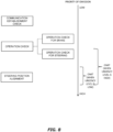
Fig. 6 illustrates a specific example of the initial check. The initial check is performed at theremote driving terminal 200. As illustrated inFig. 6 , the initial check includes several steps. - In the first step of the initial check, "communication establishment check" is performed for checking that communication between the
vehicle 100 and theremote driving terminal 200 is normally established. More specifically, in the communication establishment check, it is checked that thevehicle 100 and theremote driving terminal 200 assigned to thisvehicle 100 are normally connected to each other and are in a communicable state. For example, theremote driving terminal 200 transmits a test signal for the communication establishment check to thevehicle 100. The test signal may be a ping. Then, when theremote driving terminal 200 normally receives a response signal transmitted from thevehicle 100 in response to the test signal, it is determined that the communication is normally established. When it is determined that the communication is normally established, it means that necessary information can be accurately transmitted and received between thevehicle 100 and theremote driving terminal 200. - By the communication establishment check being completed, it is guaranteed that the
remote driving terminal 200 can normally receive the vehicle information VCL from thevehicle 100. The initial check proceeds to the next step, and "steering position alignment" is performed. The steering position alignment means bringing a steering angle of the steering operation member of theremote driving terminal 200 in line with a steering angle of thevehicle 100. The steering angle of thevehicle 100 is a steering angle of a steering wheel of thevehicle 100. Alternatively, the steering angle of thevehicle 100 may be calculated from a steering angle of the wheels of thevehicle 100. Information about the steering angle of the steering wheel or the steering angle of the wheels of thevehicle 100 can be acquired from the vehicle information VCL transmitted from thevehicle 100 to theremote driving terminal 200. The steering angle of the steering operation member of theremote driving terminal 200 is detected by the sensor installed in the steering operation member. -
Fig. 7 is a diagram illustrating an example of an image displayed on the display device of theremote driving terminal 200 when the steering position alignment is performed. A travelingtrajectory 221, which is shown by dotted lines, represents a traveling trajectory of thevehicle 100 calculated from the current steering angle of thevehicle 100. On the other hand, a travelingtrajectory 222, which is shown by solid lines, represents a traveling trajectory of thevehicle 100 calculated from the steering angle of the steering operation member of theremote driving terminal 200. Theremote driving terminal 200 draws the travelingtrajectories remote driving terminal 200 displays the image on which thetravel trajectories trajectories trajectory 221 and the travelingtrajectory 222 come into line with each other. Whether the two trajectories are in line with each other may be automatically determined by theremote driving terminal 200 or may be manually determined by the remote operator X. In the case where the determination is made manually, the remote operator X uses a button or the like of theremote operation member 230 to input information indicating that the two trajectories come into contact with each other. - By the steering position alignment being completed, it is ready to reflect the operation amount of the steering operation member in steering of the wheels of the
vehicle 100. Thereafter, the remote driving information REM can be transmitted from theremote driving terminal 200 to thevehicle 100. - Reference is made again to
Fig. 6 . After the steering position alignment is completed and the steering angle of the steering operation member and the steering angle of the wheels correspond to each other, an operation check is performed. The operation check is for checking that the operation amount of the remote operator X transmitted to thevehicle 100 as the remote driving information REM is reflected in the operation of theactuator 130, that is, theactuator 130 operates in response to the operation amount of the remote operator X. The operation check includes an operation check for the brake and an operation check for the steering. Order of performing the operation check for the brake and performing the operation check for the steering is not limited. - The operation check for the brake is for checking that the operation amount of the brake input into the brake pedal of the
remote operation member 230 by the remote operator X is reflected in operation of the brake actuator of thevehicle 100. Theremote driving terminal 200 transmits a test signal to thevehicle 100 for requesting the brake actuator to operate. For example, theremote driving terminal 200 transmits the remote driving information REM including the operation amount of the brake pedal of the remote operation member 230 (test signal) to thevehicle 100. The brake hydraulic pressure is expected to change normally if the brake actuator operates normally in response to this test signal. Therefore, theremote driving terminal 200 receives the vehicle information VCL from thevehicle 100 and monitors information about the brake hydraulic pressure included in the vehicle information VCL. If the brake hydraulic pressure changes as expected in response to the transmission of the test signal, theremote driving terminal 200 determines that the brake actuator operates normally. If the brake actuator operates normally, the operation check for the brake is finished. - The operation check for the steering is performed for checking that the operation amount input into the steering operation member of the
remote operation member 230 by the remote operator X is reflected in operation of the steering actuator and the wheels of thevehicle 100 steers. Theremote driving terminal 200 transmits a test signal to thevehicle 100 for requesting the steering actuator to operate. For example, theremote driving terminal 200 transmits the remote driving information REM including the operation amount of the steering operation member of the remote operation member 230 (test signal) to thevehicle 100. The steering angle of thevehicle 100 is expected to change normally if the steering actuator operates normally in response to this test signal. Therefore, theremote driving terminal 200 receives the vehicle information VCL from thevehicle 100 and monitors the steering angle information included in the vehicle information VCL. If the steering angle of thevehicle 100 changes as expected in response to the transmission of the test signal, theremote driving terminal 200 determines that the steering actuator operates normally. If the steering actuator operates normally, the operation check for the steering is finished. - The specific example of the initial check is described above. When detecting the first situation, the
remote driving system 1 first performs the initial check exemplified inFig. 6 . Then, after it is checked that the remote driving can be started as a result of the initial check, theremote driving system 1 starts the remote driving. In other words, theremote driving system 1 cannot start the remote driving until the initial check is finished. If the initial check takes a long time, the time when the remote driving is started becomes late accordingly. - However, there is a possibility that the remote driving of the
vehicle 100 is required to start early in a case where the first situation is an urgent situation. For example, in a case where thevehicle 100 stops in a dangerous area, it is required to start the remote driving early. In order to start the remote driving early, it is necessary to finish the initial check early. - Therefore, when detecting the first situation, in which the remote driving of the
vehicle 100 is required, theremote driving system 1 acquires an " urgency level," which is an index indicating a degree of urgency of the first situation. Then, theremote driving system 1 omits a part of the initial check according to the urgency level. By omitting a part of the initial check, the time necessary for the initial check can be shortened, and the remote driving can be started early. That is, it is possible to smoothly start the remote driving in consideration of the urgency level of the situation in which the remote driving of thevehicle 100 is required. - Omitting a part of the initial check means omitting any one or more steps from among the plurality of steps included in the initial check. Which process is omitted is determined based on the urgency level and "priority".
- First, the priority is described. The priority of omission is set for each process included in the initial check in accordance with content of each process.
Fig. 8 is a priority map showing the priority of omission. The priority map is stored in any of thememory 170 of thevehicle 100, thememory 270 of theremote driving terminal 200, and thememory 370 of themanagement device 300. When the initial check is omitted, a process having high priority is preferentially omitted in accordance with a priority map like this. - As shown in the priority map of
Fig. 8 , the priority of omission of the operation check is higher than that of the communication establishment check, and the priority of omission of the steering position alignment is higher than that of the operation check. - The communication establishment check is a process that is most important to be performed in advance when the remote driving of the
vehicle 100 is started. If the communication between thevehicle 100 and theremote driving terminal 200 is not normally established, the vehicle information VCL and the remote driving information REM cannot be transmitted and received between thevehicle 100 and theremote driving terminal 200. If the vehicle information VCL is not normally transmitted from thevehicle 100 to theremote driving terminal 200, the remote operator X cannot obtain information necessary for the remote driving. Further, if the remote driving information REM is not normally transmitted from theremote driving terminal 200 to thevehicle 100, the remote driving cannot be performed in the first place. Therefore, the priority of omission of the communication establishment check is set to be the lowest. - Conversely, the steering position alignment is not necessarily required to be performed before the remote driving is started. In a case where the steering position alignment is performed as the initial check, the remote operator X can start to operate the steering operation member with the steering angle of the steering operation member being in line with the steering angle of the wheels, and thus can easily get the feel of the steering. However, even if the steering angle of the steering operation member is not in line with the steering angle of the wheels, the remote operator X can operate the steering operation member to input the operation amount. Therefore, the priority of omission of the steering position alignment is set to be the highest.
- In addition, among the operation check, the priority of omission of the operation check for the steering is set to be higher than the priority omission of the operation check for the brake. Between the brake and the steering, the operation check for the brake is more important to be performed in advance than that for the steering. This is because, it is considered that if a situation in which the
vehicle 100 needs to avoid danger urgently, the remote operator X operates the brake first. Therefore, the priority of omission of the operation check for the steering is set to be higher than that for the brake. - Next, the urgency level will be described. When a part of the initial check is omitted, an amount of omission of the initial check is determined based on the urgency level. The remote driving is required to be started earlier as the urgency level becomes higher. Therefore, the amount of omission of the initial check is made larger as the urgency level becomes higher, and the amount of omission of the initial check is made smaller as the urgency level becomes lower.
- The following are examples of a method for calculating the urgency level. For example, in a case where a situation in which the position of the
vehicle 100 deviates from the target path is detected as the first situation as shown inFig. 5 , the urgency level may be calculated based on the deviation amount of the position of thevehicle 100 from the target path. In this case, the urgency level is calculated to be higher as the deviation amount becomes larger. - Alternatively, the urgency level may be calculated based on a situation that the
vehicle 100 is in at the time of detection of the first situation. For example, the urgency level may be calculated as follows. When thevehicle 100 is in a dangerous situation, the urgency level is calculated to be the highest. When the vehicle is not in the dangerous situation but in a situation where the vehicle may interfere with other traffic participants, the urgency level is calculated to be the next highest. In the other cases, the urgency level is calculated to be still lower. The dangerous situation is, for example, a situation in which it is raining heavily and thevehicle 100 is passing an underpass or is stopped in an underpass. As other examples, the dangerous situation is a situation where an accident such as a fire occurs at a place where thevehicle 100 is located or in the vicinity thereof or a situation where thevehicle 100 is in a railroad crossing and alarm sound is ringing. Examples of a situation where the vehicle may interfere with other traffic participants includes a situation where an emergency vehicle is approaching thevehicle 100. - The
remote driving system 1 can determine a situation like these based on information acquired from theinfrastructure sensor 400 or thesensor group 120. For example, theremote driving system 1 can detect a situation where it rains heavily based on information acquired from the rainfall sensor of thesensor group 120 or the rainfall sensor of theinfrastructure sensor 400. As another example, theremote driving system 1 can determine that thevehicle 100 is passing or stopping in the underpass or the situation around thevehicle 100 including whether the emergency vehicle is approaching based on information acquired from the in-vehicle camera or the infrastructure camera. - As another example of the method for calculating the urgency level, in a case where the
vehicle 100 is stopped or is expected to stop when the first situation is detected, the urgency level may be calculated based on a stop position of thevehicle 100. For example, the urgency level may be calculated as follows. When the stop position of thevehicle 100 is in the dangerous area, the urgency level is calculated to be the highest. When the stop position of thevehicle 100 is not in the dangerous area but in an area where thevehicle 100 may interfere with other traffic participants, the urgency level is calculated to be the next highest. In the other cases, the urgency level is calculated to be still lower. - The dangerous area mentioned here is a place where the
vehicle 100 may be in danger if thevehicle 100 continues to stop in the area. Examples of the dangerous area include an area on a track of a streetcar, an area in the railroad crossing, and a stopping prohibited area. Examples of the stopping prohibited area include an area in front of a fire station. Examples of the area where thevehicle 100 may interfere with other traffic participants include the vicinity of an intersection and a road with a heavy traffic. - The
remote driving system 1 can determine the stop position of thevehicle 100 based on information detected by theinfrastructure sensor 400 or thesensor group 120. For example, theremote driving system 1 can determine that thevehicle 100 is stopped in the railroad crossing by acquiring the image captured by the in-vehicle camera or the infrastructure camera. Alternatively, the stop position of thevehicle 100 may be acquired by comparing the map information indicating a location of the railroad, the railroad crossing, or the like and the position information acquired from the GNSS sensor of thesensor group 120. The map information is stored in any of thememory 170 of thevehicle 100, thememory 270 of theremote driving terminal 200, and thememory 370 of themanagement device 300. Theremote driving system 1 may determine whether the traffic is heavy at the stop position of thevehicle 100 based on road traffic information which themanagement device 300 has, road traffic information acquired from an external server, or the like. - Processing executed by the
remote driving system 1 will be described with reference toFigs. 9 and10 . -
Fig. 9 is a block diagram illustrating an example of a functional configuration of theremote driving system 1.Fig. 10 is a flowchart illustrating an example of processing executed by theremote driving system 1. Theremote driving system 1 includes a firstsituation detection unit 11, an urgencylevel calculation unit 12, aninitial check unit 13, and a remote driving startdetermination unit 14 as functional blocks. - In Step S110, the first
situation detection unit 11 detects the first situation. The first situation is a situation in which the remote driving of thevehicle 100 is required. A processing entity which realizes the firstsituation detection unit 11 may be theprocessor 160 of thevehicle 100 or theprocessor 360 of themanagement device 300. For example, theprocessor 160 of thevehicle 100 may detect the first situation based on the information acquired from thesensor group 120. Alternatively, theprocessor 360 of themanagement device 300 may detect the first situation based on the information acquired from theinfrastructure sensor 400. The firstsituation detection unit 11 transmits information indicating that the first situation is detected to the urgencylevel calculation unit 12, and then the processing proceeds to Step S120. - In Step S120, the urgency
level calculation unit 12 calculates the urgency level. A processing entity which realizes the urgencylevel calculation unit 12 may be theprocessor 160, theprocessor 260, or theprocessor 360. Alternatively, the urgencylevel calculation unit 12 may be realized by cooperation of these processors. - For example, the
processor 160 of thevehicle 100 acquires information about the stop position of thevehicle 100 from the GNSS sensor of thesensor group 120. Theprocessor 160 also acquires information indicating a location of the dangerous area from the map information stored in thememory 170. Then, theprocessor 160 calculates the urgency level based on whether the stop position ofvehicle 100 is included in the dangerous area or not. As another example, theprocessor 360 of themanagement device 300 may detect the traveling position of thevehicle 100 based on the infrastructure information acquired from theinfrastructure sensor 400. Then, theprocessor 160 or theprocessor 360 may calculate the urgency level by comparing the traveling position of thevehicle 100 with the target path. The urgencylevel calculation unit 12 transmits information about the calculated urgency level to theinitial check unit 13, and then the processing proceeds to Step S130. - In Step S130, the
initial check unit 13 performs the initial check. Theinitial check unit 13 is realized by theprocessor 260 of theremote driving terminal 200. When performing the initial check, theinitial check unit 13 omits a part of the initial check in accordance with the urgency level calculated by the urgencylevel calculation unit 12. Which step (steps) of the initial check is omitted is determined in accordance with to the urgency level and the priority as described above. When the initial check is finished, theinitial check unit 13 transmits the result of the initial check to the remote driving startdetermination unit 14, and then the processing proceeds to Step S140. - In Step S140, the remote driving start
determination unit 14 determines whether the remote driving can be started or not. A processing entity which realizes the remote driving startdetermination unit 14 may be theprocessor 160, theprocessor 260, or theprocessor 360. Alternatively, the remote driving startdetermination unit 14 may be realized by cooperation of these processors. The remote driving startdetermination unit 14 determines whether the remote driving can be started or not according to the result of the initial check received from theinitial check unit 13. If the result of the initial check indicates that the remote driving cannot be started (Step S140; No), the processing ends. - On the other hand, if the result of the initial check indicates that the remote driving can be started (Step S140; Yes), the processing proceeds to Step S150. In Step S150, the remote driving start
determination unit 14 starts the remote driving of thevehicle 100. -
Fig. 11 is a time chart illustrating an effect of omitting a part of the initial check of theremote driving system 1. An upper chart shows a case in a comparative example, and a lower chart shows a case in an example according to the embodiment realized by theremote driving system 1. At time T1, the first situation is detected. It is the same in both the comparative example and the example according to the embodiment that the initial check is started in response to the detection of the first situation. - In the comparative example, the remote driving is started at time T3 after the initial check is finished. On the other hand, in the example according to the embodiment, since a part of the initial check is omitted, the time required for the initial check is shortened. Therefore, the remote driving is started at time T2, which is the time earlier than time T3.
- As described above, according to the
remote driving system 1 of the present embodiment, a part of the initial check is omitted in accordance with the urgency level, and thus the initial check can be finished early. In this way, the time from when the remote driving is required to when the remote driving is started can be shortened. Further, when the urgency level is particularly high, the time until the remote driving is started can be further shortened by increasing the amount of omission. In addition, which step of the initial check is omitted is determined according to the priority. Since the priority of a particularly important process is set to be low, this process is performed without being omitted, and it is possible to prevent a failure from being found after the remote driving is started. In this way, the remote driving can be started smoothly. - As an example of a scene to which the
remote driving system 1 according to the present embodiment is applied, a scene of "autonomous transportation in a factory" is considered. - In the autonomous transportation in the factory, the autonomous driving vehicle autonomously travels in a factory ground. For example, the autonomous driving vehicle assembled in an assembly factory travels from the assembly factory to a yard by autonomously traveling along a predetermined route. One or more infrastructure cameras are installed on a road from the assembly factory to the yard. By using the infrastructure camera, the
management device 300 of theremote driving system 1 can remotely monitor the autonomous driving vehicle that is autonomously traveling. - When a situation in which the automatic driving of the autonomous driving vehicle becomes difficult for some reason and the vehicle deviates from the target route is detected, the initial check is performed to start the remote driving. In a case where a route on which the autonomous driving vehicle travels is determined in advance as in the case of the autonomous transportation in the factory, the
management device 300 can detect such a situation based on the information about the route stored in thememory 370 and the image captured by the infrastructure camera. When the initial check is performed, a part of the initial check is omitted according to the deviation amount from the target route. By omitting a part of the initial check, the remote driving can be quickly started. When the situation in which it is difficult that the autonomous driving vehicle continue to autonomously travel occurs, it is also considered to send a staff to the site and start to drive the vehicle by manual driving, but it takes time and labor. Dealing with the situation by the remote driving is more convenient and reduces time and labor. -
Fig. 12 is a diagram for explaining the first modification. In the first modification, the in-vehicle camera includes a front camera capturing a forward image as seen from thevehicle 100 and a side camera capturing a lateral image as seen from thevehicle 100. The initial check includes a camera check. The camera check is for checking that the in-vehicle camera operates normally. In other words, the camera check is checking that the image captured by the in-vehicle camera is normally acquired. The camera check further includes a front camera check for the front camera and a side camera check for the side camera. - The priority of omission of the side camera check is set to be higher than the priority of omission of the front camera check. It is considered that the remote operator X acquires more information from the image captured by the front camera than from that by the side camera during the remote driving. Therefore, the priority of omission of the side camera check is set to be higher. Similarly, in a case where the in-vehicle cameras include a camera other than the side camera, the priority of omission of the camera check for the camera other than the front camera is set to be higher than the priority of omission of the front camera check.
- As a specific example of an applied scene, a case where the
vehicle 100 is urgently stopped in the railroad crossing is considered. Since the urgency level of the first situation is high, the camera check for the camera other than the front camera is omitted, and in the initial check, it is checked that at least the front camera is normally operating. The remote operator X can start thevehicle 100 traveling by the remote driving referring to at least the image captured by the front camera and can make thevehicle 100 exit from the railroad crossing early. -
Fig. 13 is a block diagram illustrating an example of a functional configuration of theremote driving system 1 according to the second modification. In the second modification, theremote driving system 1 includes a vehiclespeed limitation unit 15 as a functional block. - The vehicle
speed limitation unit 15 acquires information about whether the initial check is omitted or not from theinitial check unit 13. When a part of the initial check is omitted, the vehiclespeed limitation unit 15 sets an upper limit to a vehicle speed of thevehicle 100. The upper limit of the vehicle speed set here may be determined unconditionally or may be set in accordance with where thevehicle 100 is located. For example, the vehicle speed may be set to be a predetermined amount lower than a speed limit of the road on which thevehicle 100 is. - The vehicle
speed limitation unit 15 may be included in thevehicle 100. In this case, thecontrol device 150 controls thevehicle 100 such that the vehicle speed does not exceed the upper limit. Alternatively, the vehiclespeed limitation unit 15 may be included in theremote driving terminal 200. In this case, the vehiclespeed limitation unit 15 limits the input of the remote operator X such that the vehicle speed does not exceed the upper limit. Alternatively, the vehiclespeed limitation unit 15 may be included in themanagement device 300. In this case, information about the vehicle speed set by the management device is transmitted to thevehicle 100 or theremote driving terminal 200. - In this modification, since the vehicle speed is limited, it is possible to improve safety of the traveling of the
vehicle 100 even when a part of the initial check is omitted.
Claims (12)
- A remote driving system (1) that performs remote driving of a vehicle (100) based on an operation amount input into a remote driving terminal (200), the remote driving system (1) comprising at least one processor (160, 260, 360) configured to:detect a first situation in which the remote driving of the vehicle (100) is required; andperform an initial check for checking that the remote driving can be started at the remote driving terminal (200) when the first situation is detected, characterised in thatthe initial check at the remote driving terminal (200) includes:a first initial check that checks communication establishment with the vehicle (100);a second initial check that checks that a brake actuator (130) of the vehicle (100) operates in response to the operation amount of a brake transmitted to the vehicle;a third initial check that checks that a steering actuator (130) of the vehicle (100) operates in response to the operation amount of a steering; anda fourth initial check that performs steering position alignment between the vehicle (100) and the remote driving terminal (200), and whereinat least one processor (160, 260, 360) is further configured to:acquire an urgency level of the first situation; andomit a part of the initial check according to the urgency level.
- The remote driving system (1) according to claim 1, wherein
the at least one processor (160, 260, 360) is further configured to increase an omission amount of the initial check as the urgency level increases. - The remote driving system (1) according to claim 2, whereinthe first situation is a situation in which a deviation amount of the vehicle (100) from a target path exceeds a threshold value, andthe urgency level is higher when the deviation amount is a second amount than when the deviation amount is a first amount smaller than the second amount.
- The remote driving system (1) according to claim 2, whereinthe urgency level in a case where a stop position of the vehicle (100) is in a dangerous area is higher than the urgency level in a case where the stop position is outside the dangerous area, andthe dangerous area includes at least one of an area on a track of a streetcar, an area in a railroad crossing, and a stopping prohibited area.
- The remote driving system (1) according to any one of claims 1 to 4, wherein
the fourth initial check is omitted prior to the first initial check, the second initial check, and the third initial check. - The remote driving system (1) according to claim 5, wherein
at least one of the second initial check and the third initial check is omitted prior to the first initial check. - The remote driving system (1) according to claim 6, wherein
the third initial check is omitted prior to the second initial check. - The remote driving system (1) according to any one of claims 1 to 4, whereinthe initial check at the remote driving terminal (200) further includes at least a camera check for checking that an in-vehicle (100) camera mounted on the vehicle (100) operates normally,the in-vehicle (100) camera includes a front camera capturing a forward image as seen from the vehicle (100) and a side camera capturing a lateral image as seen from the vehicle (100), andthe camera check for the side camera is omitted prior to the camera check for the front camera.
- The remote driving system (1) according to any one of claims 1 to 4, wherein
the at least one processor (160, 260, 360) is further configured to set an upper limit for a vehicle (100) speed of the vehicle (100) when omitting a part of the initial check. - The remote driving system (1) according to any one of claims 1 to 4, wherein
the at least one processor (160, 260, 360) is further configured to:acquire infrastructure information including an image captured by an infrastructure camera installed in an area where the vehicle (100) travels; anddetect the first situation based on the infrastructure information. - A remote driving terminal (200) that performs remote driving of a vehicle (100) based on an operation amount input by a remote operator (X), the remote driving terminal (200) comprising at least one processor (260) configured to:acquire information indicating that a first situation in which the remote driving of the vehicle (100) is required is detected; and
perform an initial check for checking that the remote driving terminal (200) can start the remote driving when the first situation is detected, characterised in thatthe initial check at the remote driving terminal (200) includes:a first initial check that checks communication establishment with the vehicle (100);a second initial check that checks that a brake actuator (130) of the vehicle (100) operates in response to the operation amount of a brake transmitted to the vehicle (100);a third initial check that checks that a steering actuator (130) of the vehicle (100) operates in response to the operation amount of a steering,a fourth initial check that performs steering position alignment between the vehicle (100) and the remote driving terminal (200), and whereinat least one processor (160, 260, 360) is further configured to: acquire an urgency level of the first situation; andomit a part of the initial check according to the urgency level. - A method for performing remote driving of a vehicle (100) based on an operation amount input into a remote driving terminal (200), the method comprising:detecting a first situation in which the remote driving of the vehicle (100) is required; and
performing an initial check for checking that the remote driving can be started at the remote driving terminal (200) when the first situation is detected, characterised in thatthe initial check at the remote driving terminal (200) includes:a first initial check that checks communication establishment with the vehicle (100);a second initial check that checks that a brake actuator (130) of the vehicle (100) operates in response to the operation amount of a brake transmitted to the vehicle (100);a third initial check that checks that a steering actuator (130) of the vehicle (100) operates in response to the operation amount of a steering,a fourth initial check that performs steering position alignment between the vehicle (100) and the remote driving terminal (200), and whereinthe method further comprises:
acquiring an urgency level of the first situation; andomitting a part of the initial check according to the urgency level.
Applications Claiming Priority (1)
| Application Number | Priority Date | Filing Date | Title |
|---|---|---|---|
| JP2023009602A JP7771997B2 (en) | 2023-01-25 | 2023-01-25 | Remote driving system, remote driving terminal, and method for remote driving |
Publications (3)
| Publication Number | Publication Date |
|---|---|
| EP4407397A1 EP4407397A1 (en) | 2024-07-31 |
| EP4407397C0 EP4407397C0 (en) | 2025-07-09 |
| EP4407397B1 true EP4407397B1 (en) | 2025-07-09 |
Family
ID=89223086
Family Applications (1)
| Application Number | Title | Priority Date | Filing Date |
|---|---|---|---|
| EP23216690.0A Active EP4407397B1 (en) | 2023-01-25 | 2023-12-14 | Remote driving system, remote driving terminal, and method for remote driving |
Country Status (5)
| Country | Link |
|---|---|
| US (1) | US20240248479A1 (en) |
| EP (1) | EP4407397B1 (en) |
| JP (1) | JP7771997B2 (en) |
| KR (1) | KR20240117490A (en) |
| CN (1) | CN118393926A (en) |
Family Cites Families (7)
| Publication number | Priority date | Publication date | Assignee | Title |
|---|---|---|---|---|
| CN106030432B (en) * | 2014-02-14 | 2020-04-07 | 山特维克矿山工程机械有限公司 | Arrangement for initiating a remote operation mode |
| JP6706845B2 (en) | 2017-02-28 | 2020-06-10 | パナソニックIpマネジメント株式会社 | Remote control device, remote control method |
| US11292480B2 (en) | 2018-09-13 | 2022-04-05 | Tusimple, Inc. | Remote safe driving methods and systems |
| JP7200864B2 (en) * | 2019-07-17 | 2023-01-10 | トヨタ自動車株式会社 | vehicle controller |
| DE102019214461A1 (en) | 2019-09-23 | 2021-03-25 | Robert Bosch Gmbh | Method for remote control of a motor vehicle |
| JP2022022075A (en) * | 2020-07-22 | 2022-02-03 | 株式会社デンソー | Vehicle control device and vehicle control method |
| CN114981853A (en) | 2020-12-10 | 2022-08-30 | 松下电器(美国)知识产权公司 | Information processing method and information processing system |
-
2023
- 2023-01-25 JP JP2023009602A patent/JP7771997B2/en active Active
- 2023-12-14 EP EP23216690.0A patent/EP4407397B1/en active Active
- 2023-12-22 US US18/394,467 patent/US20240248479A1/en active Pending
-
2024
- 2024-01-19 CN CN202410084444.1A patent/CN118393926A/en active Pending
- 2024-01-23 KR KR1020240010232A patent/KR20240117490A/en active Pending
Also Published As
| Publication number | Publication date |
|---|---|
| KR20240117490A (en) | 2024-08-01 |
| JP7771997B2 (en) | 2025-11-18 |
| EP4407397C0 (en) | 2025-07-09 |
| JP2024105061A (en) | 2024-08-06 |
| US20240248479A1 (en) | 2024-07-25 |
| CN118393926A (en) | 2024-07-26 |
| EP4407397A1 (en) | 2024-07-31 |
Similar Documents
| Publication | Publication Date | Title |
|---|---|---|
| CN112660156B (en) | Vehicle Control Systems | |
| CN110290998B (en) | Control system and control method for vehicle | |
| JP5888407B2 (en) | Driving assistance device | |
| CN114761300B (en) | Driving control method and driving control device | |
| US11755022B2 (en) | Vehicle control device | |
| JP2018180859A (en) | Automatic driving system | |
| US20200168102A1 (en) | Platooning system | |
| CN111758125B (en) | Driving control device, driving control method, and program | |
| US11340090B2 (en) | Vehicle control device | |
| EP4050446A1 (en) | Remote support system and remote support method | |
| JP2019530609A (en) | Modular architecture autonomous vehicle | |
| JPWO2020123143A5 (en) | ||
| EP4407397B1 (en) | Remote driving system, remote driving terminal, and method for remote driving | |
| JP7429111B2 (en) | Traffic control equipment and vehicle control equipment | |
| EP4407401B1 (en) | Remote driving system, remote driving terminal, and method for remote driving | |
| JP7429112B2 (en) | control device | |
| KR20240127433A (en) | Vehicle driving control device, method for obtaining vehicle location information, computer-readable recording medium, and program for obtaining vehicle location information | |
| CN113554864A (en) | System and method for post-processing of highway traffic accidents | |
| CN115071753B (en) | Mobile control system, mobile body and control method | |
| JP2024004281A (en) | vehicle control system | |
| CN121057683A (en) | Driving assistance systems and methods for vehicles | |
| CN116788255A (en) | Method for implementing an at least partially automated driving function | |
| JP2021081962A (en) | Control apparatus |
Legal Events
| Date | Code | Title | Description |
|---|---|---|---|
| PUAI | Public reference made under article 153(3) epc to a published international application that has entered the european phase |
Free format text: ORIGINAL CODE: 0009012 |
|
| STAA | Information on the status of an ep patent application or granted ep patent |
Free format text: STATUS: REQUEST FOR EXAMINATION WAS MADE |
|
| 17P | Request for examination filed |
Effective date: 20231214 |
|
| AK | Designated contracting states |
Kind code of ref document: A1 Designated state(s): AL AT BE BG CH CY CZ DE DK EE ES FI FR GB GR HR HU IE IS IT LI LT LU LV MC ME MK MT NL NO PL PT RO RS SE SI SK SM TR |
|
| GRAP | Despatch of communication of intention to grant a patent |
Free format text: ORIGINAL CODE: EPIDOSNIGR1 |
|
| STAA | Information on the status of an ep patent application or granted ep patent |
Free format text: STATUS: GRANT OF PATENT IS INTENDED |
|
| INTG | Intention to grant announced |
Effective date: 20250428 |
|
| GRAS | Grant fee paid |
Free format text: ORIGINAL CODE: EPIDOSNIGR3 |
|
| GRAA | (expected) grant |
Free format text: ORIGINAL CODE: 0009210 |
|
| STAA | Information on the status of an ep patent application or granted ep patent |
Free format text: STATUS: THE PATENT HAS BEEN GRANTED |
|
| AK | Designated contracting states |
Kind code of ref document: B1 Designated state(s): AL AT BE BG CH CY CZ DE DK EE ES FI FR GB GR HR HU IE IS IT LI LT LU LV MC ME MK MT NL NO PL PT RO RS SE SI SK SM TR |
|
| REG | Reference to a national code |
Ref country code: GB Ref legal event code: FG4D |
|
| REG | Reference to a national code |
Ref country code: CH Ref legal event code: EP |
|
| REG | Reference to a national code |
Ref country code: IE Ref legal event code: FG4D |
|
| REG | Reference to a national code |
Ref country code: DE Ref legal event code: R096 Ref document number: 602023004711 Country of ref document: DE |
|
| U01 | Request for unitary effect filed |
Effective date: 20250805 |
|
| U07 | Unitary effect registered |
Designated state(s): AT BE BG DE DK EE FI FR IT LT LU LV MT NL PT RO SE SI Effective date: 20250813 |
|
| U20 | Renewal fee for the european patent with unitary effect paid |
Year of fee payment: 3 Effective date: 20251110 |
|
| PG25 | Lapsed in a contracting state [announced via postgrant information from national office to epo] |
Ref country code: IS Free format text: LAPSE BECAUSE OF FAILURE TO SUBMIT A TRANSLATION OF THE DESCRIPTION OR TO PAY THE FEE WITHIN THE PRESCRIBED TIME-LIMIT Effective date: 20251109 |
|
| PG25 | Lapsed in a contracting state [announced via postgrant information from national office to epo] |
Ref country code: NO Free format text: LAPSE BECAUSE OF FAILURE TO SUBMIT A TRANSLATION OF THE DESCRIPTION OR TO PAY THE FEE WITHIN THE PRESCRIBED TIME-LIMIT Effective date: 20251009 |
|
| PG25 | Lapsed in a contracting state [announced via postgrant information from national office to epo] |
Ref country code: HR Free format text: LAPSE BECAUSE OF FAILURE TO SUBMIT A TRANSLATION OF THE DESCRIPTION OR TO PAY THE FEE WITHIN THE PRESCRIBED TIME-LIMIT Effective date: 20250709 |
|
| PG25 | Lapsed in a contracting state [announced via postgrant information from national office to epo] |
Ref country code: GR Free format text: LAPSE BECAUSE OF FAILURE TO SUBMIT A TRANSLATION OF THE DESCRIPTION OR TO PAY THE FEE WITHIN THE PRESCRIBED TIME-LIMIT Effective date: 20251010 |
|
| PG25 | Lapsed in a contracting state [announced via postgrant information from national office to epo] |
Ref country code: PL Free format text: LAPSE BECAUSE OF FAILURE TO SUBMIT A TRANSLATION OF THE DESCRIPTION OR TO PAY THE FEE WITHIN THE PRESCRIBED TIME-LIMIT Effective date: 20250709 |
|
| PG25 | Lapsed in a contracting state [announced via postgrant information from national office to epo] |
Ref country code: RS Free format text: LAPSE BECAUSE OF FAILURE TO SUBMIT A TRANSLATION OF THE DESCRIPTION OR TO PAY THE FEE WITHIN THE PRESCRIBED TIME-LIMIT Effective date: 20251009 |
|
| PG25 | Lapsed in a contracting state [announced via postgrant information from national office to epo] |
Ref country code: ES Free format text: LAPSE BECAUSE OF FAILURE TO SUBMIT A TRANSLATION OF THE DESCRIPTION OR TO PAY THE FEE WITHIN THE PRESCRIBED TIME-LIMIT Effective date: 20250709 |