EP4407392A1 - Machining control device, control method for machining control device, and program - Google Patents
Machining control device, control method for machining control device, and program Download PDFInfo
- Publication number
- EP4407392A1 EP4407392A1 EP24154671.2A EP24154671A EP4407392A1 EP 4407392 A1 EP4407392 A1 EP 4407392A1 EP 24154671 A EP24154671 A EP 24154671A EP 4407392 A1 EP4407392 A1 EP 4407392A1
- Authority
- EP
- European Patent Office
- Prior art keywords
- tool
- axis
- mesh data
- workpiece
- contact
- Prior art date
- Legal status (The legal status is an assumption and is not a legal conclusion. Google has not performed a legal analysis and makes no representation as to the accuracy of the status listed.)
- Pending
Links
Images


Classifications
-
- G—PHYSICS
- G05—CONTROLLING; REGULATING
- G05B—CONTROL OR REGULATING SYSTEMS IN GENERAL; FUNCTIONAL ELEMENTS OF SUCH SYSTEMS; MONITORING OR TESTING ARRANGEMENTS FOR SUCH SYSTEMS OR ELEMENTS
- G05B19/00—Programme-control systems
- G05B19/02—Programme-control systems electric
- G05B19/18—Numerical control [NC], i.e. automatically operating machines, in particular machine tools, e.g. in a manufacturing environment, so as to execute positioning, movement or co-ordinated operations by means of programme data in numerical form
- G05B19/406—Numerical control [NC], i.e. automatically operating machines, in particular machine tools, e.g. in a manufacturing environment, so as to execute positioning, movement or co-ordinated operations by means of programme data in numerical form characterised by monitoring or safety
- G05B19/4061—Avoiding collision or forbidden zones
-
- G—PHYSICS
- G05—CONTROLLING; REGULATING
- G05B—CONTROL OR REGULATING SYSTEMS IN GENERAL; FUNCTIONAL ELEMENTS OF SUCH SYSTEMS; MONITORING OR TESTING ARRANGEMENTS FOR SUCH SYSTEMS OR ELEMENTS
- G05B19/00—Programme-control systems
- G05B19/02—Programme-control systems electric
- G05B19/18—Numerical control [NC], i.e. automatically operating machines, in particular machine tools, e.g. in a manufacturing environment, so as to execute positioning, movement or co-ordinated operations by means of programme data in numerical form
- G05B19/406—Numerical control [NC], i.e. automatically operating machines, in particular machine tools, e.g. in a manufacturing environment, so as to execute positioning, movement or co-ordinated operations by means of programme data in numerical form characterised by monitoring or safety
- G05B19/4069—Simulating machining process on screen
-
- G—PHYSICS
- G05—CONTROLLING; REGULATING
- G05B—CONTROL OR REGULATING SYSTEMS IN GENERAL; FUNCTIONAL ELEMENTS OF SUCH SYSTEMS; MONITORING OR TESTING ARRANGEMENTS FOR SUCH SYSTEMS OR ELEMENTS
- G05B2219/00—Program-control systems
- G05B2219/30—Nc systems
- G05B2219/35—Nc in input of data, input till input file format
- G05B2219/35117—Define surface by elements, meshes
Definitions
- the present invention relates to a machining control device, a control method for the machining control device, and a program.
- JP 2021-174152 A discloses a five-axis control machining tool in which a tool and a mounting table for mounting a workpiece are relatively moved by three linear axes and two rotation axes on the basis of numerical control (NC) data.
- NC numerical control
- the workpiece When the workpiece is relatively moved by the five axes of the three linear axes and the two rotation axes and machined by using the tool, the workpiece is rotatable by the two rotation axes, increasing a degree of freedom of machining.
- JP 2021-174152 A does not solve such a problem.
- an object of the present disclosure is to provide a machining control device and the like capable of determining a posture of a tool with respect to a workpiece when the tool and the workpiece are relatively moved by five axes including two rotation axes to perform machining.
- a machining control device configured to perform control of relatively moving a tool and a workpiece by five axes of a first axis and a second axis orthogonal to each other in a horizontal direction, a third axis in a vertical direction, a first rotation axis that rotates about one axis of the first axis and the second axis, and a second rotation axis that rotates about the third axis to machine the workpiece by the tool
- the machining control device comprising: a mesh data acquisition unit configured to acquire mesh data representing a shape of the workpiece using a plurality of triangular meshes; a contact point calculation unit configured to calculate, in the mesh data, a plurality of first contact points where a tip of the tool is to come into contact; a mesh data rotation unit configured to rotate the mesh data so that the tool moves along the third axis when the tool machines the workpiece; and a posture determination unit configured to calculate, for each of the plurality of first contact points and while changing a relative angle of the
- a control method of a machining control device configured to perform control of relatively moving a tool and a workpiece by five axes of a first axis and a second axis orthogonal to each other in a horizontal direction, a third axis in a vertical direction, a first rotation axis that rotates about one axis of the first axis and the second axis, and a second rotation axis that rotates about the third axis to machine the workpiece by the tool
- the control method comprising: acquiring mesh data representing a shape of the workpiece using a plurality of triangular meshes; calculating, in the mesh data, a plurality of first contact points where a tip of the tool is to come into contact; rotating the mesh data so that the tool moves along the third axis when the tool machines the workpiece; and calculating, for each of the plurality of first contact points and while changing a relative angle of the tool with respect to the mesh data for respective predetermined angles, a second contact point where the tip of the tool and
- FIG. 1 is a diagram illustrating an example of a machining control system 100.
- the machining control system 100 includes a server 101, a plurality of machining control devices 102, and a plurality of machine tools 103.
- the server 101 and the machining control devices 102 are connected via a network NW such as the Internet.
- Each machining control device 102 may perform different machining control in accordance with a type of machining performed by the machine tool 103.
- the machining type may be, for example, island milling in which machining is performed so as to leave an island shape, blind hole boring in which a blind hole is formed, or through-hole drilling in which a through-hole is formed.
- the number of the machining control devices 102 and the machine tools 103 included in the machining control system 100 may be one each.
- the server 101 is a server that stores mesh data.
- the server 101 is installed at a predetermined location by, for example, a company that provides the machining control system 100.
- the mesh data is drawing data representing a shape of a machined object (workpiece) using a plurality of triangular meshes.
- the mesh data is described as standard triangulated language (STL) data.
- the mesh data may be desired drawing data other than STL data.
- the mesh data may be data in OBJ format.
- the machining control device 102 is a computer that controls the machine tool 103.
- the machine tool 103 of the present embodiment is a numerical control (NC) machine tool that performs predetermined machining on a workpiece under the control of the machining control device 102.
- NC numerical control
- the machining control device 102 acquires mesh data from the server 101 via the network NW.
- the machining control device 102 is a computer that uses the mesh data to determine, as a posture of the tool, a relative angle of the tool with respect to the workpiece when the tool machines the workpiece. Details of the machining control device 102 will be described below.
- the machining control device 102 may acquire the mesh data from a recording medium such as a portable memory.
- a recording medium such as a portable memory.
- the machining control device 102 may acquire the mesh data from a portable memory in which the mesh data is stored.
- the machining control device 102 controls the machine tool 103.
- the machine tool 103 is provided with a tool.
- the machine tool 103 performs predetermined machining on a workpiece using the tool.
- the machining will be described as cutting.
- the machine tool 103 will be described as a tool that performs scanning line machining.
- the machine tool 103 may perform machining other than cutting, and may perform cutting other than scanning line machining.
- the machine tool 103 brings the tool into contact with a surface of the workpiece to cut the workpiece.
- the machine tool 103 brings the tool into contact with many points on the surface of the workpiece to cut the workpiece.
- the machining control device 102 uses the mesh data to determine, as the posture of the tool, the relative angle of the tool with respect to the workpiece for each point where machining is performed on the surface of the workpiece.
- the machine tool 103 controls the posture of the tool, aligning the posture with a determined posture of the tool.
- FIG. 2 is a diagram illustrating an example of the machine tool 103.
- the machine tool 103 includes a tool 151, a workpiece mounting table 152, an X-axis drive mechanism 153, a Y-axis drive mechanism 154, a Z-axis drive mechanism 155, and a B-axis drive mechanism 156.
- the tool 151 is a tool used to cut the workpiece.
- the tool 151 is, for example, an end mill. However, the tool 151 may be a tool other than an end mill.
- the workpiece mounting table 152 is a table for mounting the workpiece thereon.
- the workpiece mounting table 152 rotates around a C axis (first rotation axis) about the Z axis by drive control of a rotation drive mechanism (not illustrated) attached to the workpiece mounting table 152.
- the X-axis drive mechanism 153 moves the tool 151 linearly in an X-axis (first axis) direction.
- the Y-axis drive mechanism 154 moves the tool 151 linearly in a Y-axis (second axis) direction.
- the X axis and the Y axis are axes orthogonal to each other in the horizontal direction.
- the Z-axis drive mechanism 155 moves the tool 151 in a Z-axis (third axis) direction.
- the Z-axis direction is a vertical direction.
- the machine tool 103 moves the tool 151 downward with respect to the workpiece mounted on the workpiece mounting table 152 to bring a tip of the tool 151 into contact with the workpiece and cut the workpiece.
- the B-axis drive mechanism 156 rotates the workpiece mounting table 152 about the Y axis.
- a position of the tool 151 is controlled by the three linear axes described above. Further, the workpiece is rotated by the two rotation axes of the B axis and the C axis. Therefore, with the five axes of the three linear axes and the two rotation axes, machining can be performed by using the tool 151 at a desired position and a desired angle with respect to the workpiece.
- FIG. 3 is a block diagram illustrating an example of the machining control device 102.
- the machining control device 102 includes a control unit 201, a communication unit 202, a storage unit 203, an operation unit 204, a display unit 205, and an output unit 206.
- the machining control device 102 is not limited to the configuration of FIG. 3 and may include other elements or some of the elements may be omitted.
- the control unit 201 includes a processor and a memory.
- the control unit 201 includes a graphics processing unit (GPU) as a processor. Further, the processor may be a central processing unit (CPU).
- GPU graphics processing unit
- CPU central processing unit
- the communication unit 202 is a network interface connected to the network NW, and transmits and receives information via the network NW in accordance with instructions from the control unit 201.
- the information includes mesh data.
- the storage unit 203 includes, for example, an information recording medium such as a hard disk, a read-only memory (ROM), or a random access memory (RAM).
- the storage unit 203 is an information recording medium that holds a program executed by the processor of the control unit 201.
- the operation unit 204 includes, for example, an interface such as a keyboard, a mouse, and a button, and outputs, in accordance with an instruction operation of a user, the content of the instruction operation to the control unit 201.
- the display unit 205 is, for example, a liquid crystal display, a cathode ray tube (CRT) display, or an organic electroluminescent (EL) display.
- the display unit 205 displays information according to an instruction from the control unit 201.
- the output unit 206 outputs control information for controlling the machine tool 103 to the machine tool 103.
- the control unit 201 includes a mesh data acquisition unit 211, a contact point calculation unit 212, a mesh data rotation unit 213, and a posture determination unit 214.
- a function of the control unit 201 is a software function realized by the processor described above executing a plurality of command sets stored in the memory.
- the mesh data acquisition unit 211 acquires the mesh data representing the shape of the workpiece from the server 101 via the communication unit 202.
- the contact point calculation unit 212 calculates a plurality of contact points (first contact points) where the tip of the tool data representing the tool 151 is brought into contact with the mesh data when the workpiece is machined using the tool 151.
- the first contact point is also a target point where the tip of the tool 151 brought into contact with the workpiece and machining is performed.
- the mesh data rotation unit 213 rotates the mesh data so that tool data representing the tool 151 moves downward in the Z-axis direction.
- the tool 151 is moved downward in the Z-axis direction and brought into contact with the workpiece, thereby machining the workpiece.
- the workpiece is rotated relative to the tool 151 moving in the Z-axis direction. Therefore, the mesh data rotation unit 213 rotates the mesh data relative to the tool data.
- the posture determination unit 214 determines, as the posture of the tool 151 with respect to the workpiece, the relative angle of the tool data with respect to the mesh data when the tool 151 machines the workpiece. As described above, the tool 151 moves downward in the Z-axis direction. At this time, depending on the shape of the workpiece, the tool 151 may come into contact with another area of the workpiece before the tool 151 comes into contact with the first contact point which is the target point. The posture determination unit 214 determines the posture of the tool data that avoids such interference. Details will be described below.
- FIG. 4 is a diagram illustrating an example of division of the mesh data.
- the mesh data acquisition unit 211 acquires mesh data M.
- the contact point calculation unit 212 divides the acquired mesh data M by planes 301 at minute intervals (equal intervals) in the Z-axis direction.
- the plane 301 represented by a two dot chain line is an XY plane orthogonal to the Z-axis direction.
- the mesh data M is data representing the shape of the workpiece using a plurality of triangular meshes.
- the contact point calculation unit 212 sets the plane 301 for each minute interval, and acquires a plurality of intersection points between each plane 301 and the triangular meshes constituting the mesh data M as the first contact points.
- FIG. 5 is a diagram illustrating an example obtained by enlarging a portion of FIG. 4 .
- five triangular meshes M1 to M5 constituting the mesh data M are illustrated.
- the triangular meshes M1 to M5 are shapes of portions of the mesh data M.
- the mesh data M is divided by the planes 301 at minute intervals.
- intersection points of the triangular mesh M1 and the plane 301 are intersection points P1 and P2.
- intersection points of the triangular mesh M2 and the plane 301 are intersection points P3 and P4.
- intersection points of the triangular mesh M3 and the plane 301 are intersection points P5 and P6.
- intersection points of the triangular mesh M1 and the plane 301 are intersection points P7 and P8.
- the contact point calculation unit 212 calculates the respective intersection points P1 to P8 as the first contact points.
- FIG. 6 is a diagram illustrating an example of an outline model. As described above, many intersection points P are set as the first contact points with respect to the mesh data M. From each first contact point, the outer shape of the mesh data M is represented by point cloud data along the Z-axis direction.
- a wide plane is constituted by a triangular mesh having a wide area compared with that of a narrow plane.
- an area of a triangular mesh M10 (triangular mesh indicated by hatching) is wide.
- a distance between an intersection point P11 and an intersection point P12 of the triangular mesh M10 is long.
- the contact point calculation unit 212 sets an intersection point P13 (third intersection point) between the intersection point P11 and the intersection point P12. Accordingly, it is possible to suppress an increase in distance between intersection points. This makes it possible to reproduce the outer shape of the mesh data M in which each first contact point (each intersection point) is set as point cloud data with higher accuracy.
- the contact point calculation unit 212 may set a plurality of intersection points at regular intervals between the intersection points.
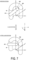
- FIG. 7 is a diagram illustrating an example of C-axis rotation of the mesh data M.
- the mesh data M represents the shape of a portion of the workpiece.
- the mesh data M in FIG. 7 constitutes a three-dimensional shape with a semicircular arc cross section.
- Tool data 401 is data representing the tool 151.
- a tip 402 of the tool data 401 represents the tip of the tool 151 that machines the workpiece.
- the tip of the tool 151 and the workpiece come into point contact with each other.
- a point 403 where the tip 402 of the tool data 401 and the mesh data M corresponding to the workpiece come into contact is referred to as a second contact point.
- the mesh data rotation unit 213 rotates the mesh data M so that a Y component of a vector (hereinafter referred to as a tool vector) in a direction in which the tool data 401 moves becomes 0. During actual machining, this rotation is realized by the machine tool 103 controlling a C-axis drive mechanism (not illustrated) to rotate the workpiece mounting table 152 around the C axis about the Z axis.
- the mesh data rotation unit 213 rotates the mesh data M as described above, the mesh data M changes from the state before rotation to the state after C-axis rotation in FIG. 7 .
- the Y component of the tool vector of the tool data 401 with respect to the mesh data M is 0.
- FIG. 8 is a diagram illustrating an example of B-axis rotation of the mesh data M.
- the after C-axis rotation in FIG. 8 is the same as the after C-axis rotation in FIG. 7 .
- the mesh data rotation unit 213 rotates the mesh data M so that an X component of the tool vector of the tool data 401 becomes 0. During actual machining, this rotation is realized by the machine tool 103 controlling the B-axis drive mechanism 156 to rotate the workpiece mounting table 152 around the B axis about the Y axis.
- the mesh data rotation unit 213 rotates the mesh data M as described above, the X component of the tool vector of the tool data 401 with respect to the mesh data M becomes 0 as illustrated by the after B-axis rotation in FIG. 8 .
- the X component and the Y component of the tool vector of the tool data 401 with respect to the mesh data M become 0.
- the machine tool 103 moves the tool 151 downward in the Z-axis direction, and brings the tip of the tool 151 into contact with the workpiece to machine the workpiece. Therefore, the posture determination unit 214 performs the processing of C-axis rotation and B-axis rotation described above, thereby setting the X component and the Y component of the tool vector of the tool data 401 with respect to the mesh data M to 0.
- the mesh data M (mesh data of a portion of the workpiece) in FIG. 7 and FIG. 8 constitutes a semicircular three-dimensional shape.
- the point to be machined is a first contact point 404 (target point).
- the posture determination unit 214 determines the posture of each first contact point (target point) with respect to the mesh data M of the tool data 401 so as to avoid the interference described above when the tool 151 machines the workpiece. Hereinafter, determination of the posture will be described.
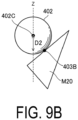
- FIGS. 9A to 9C are diagrams illustrating an example of calculation of the second contact point.
- the mesh data rotation unit 213 rotates the mesh data M so that the X component and the Y component of the tool vector of the tool data 401 with respect to the mesh data M become 0.
- the posture determination unit 214 moves the tool data 401 downward toward the mesh data M after rotation to bring the tool data 401 into contact with the mesh data M after rotation.
- the contact point at this time is the second contact point.
- the mesh data M is constituted by a plurality of triangular meshes.
- the tip 402 of the tool data 401 comes into point contact with a face, a side, or a vertex of one triangular mesh (triangular mesh M20) among the plurality of triangular meshes constituting the mesh data M.
- FIG. 9A is a diagram illustrating an example in which the tip 402 of tool data 401 comes into contact with a face of the triangular mesh M20.
- the tip 402 of the tool data 401 has a spherical shape.
- the interval between a Z-axis coordinate of a point 403A on the face of the triangular mesh M20 where the tip 402 of the tool data 401 comes into contact and a Z-axis coordinate of a center 402C of the tip 402 of the tool data 401 is defined as an interval D1.
- FIG. 9B is a diagram illustrating an example in which the tip 402 of tool data 401 comes into contact with one side of the triangular mesh M20.
- an interval between a Z-axis coordinate of a point 403B on the side of the triangular mesh M20 where the tip 402 of the tool data 401 comes into contact and a Z-axis coordinate of the center 402C of the tip 402 of the tool data 401 is defined as an interval D2.
- FIG. 9C is a diagram illustrating an example in which the tip 402 of tool data 401 comes into contact with one vertex of the triangular mesh M20.
- an interval between a Z-axis coordinate of a point 403C (vertex of the triangular mesh M20) where the tip 402 of the tool data 401 comes into contact and a Z-axis coordinate of the center 402C of the tip 402 of the tool data 401 is defined as an interval D3.
- the tip 402 of the tool data 401 corresponding to the longest interval among the intervals D1 to D3 is at the highest position with respect to the triangular mesh M20.
- the posture determination unit 214 calculates, as the second contact point, the Z-axis coordinate of the center 402C of the tip 402 of the tool data 401 corresponding to the longest interval of the intervals D1 to D3. For example, in the case of FIGS. 9A to 9C , the posture determination unit 214 calculates the Z-axis coordinate of the center 402C of the tip 402 of the tool data 401 in FIG. 9C as the second contact point.
- the contact point calculation unit 212 calculates the plurality of first contact points representing the shape of the mesh data M by point cloud data.
- the first contact point is a target point where the tip 402 of the tool data 401 of the mesh data M is to be brought into contact.
- the posture determination unit 214 determines, as the posture of the tool data 401, the relative angle of the tool data 401 with respect to the mesh data M so that the distance between the first contact point and the second contact point is the minimum distance.
- FIG. 10 is a diagram illustrating an example of determination of the posture of the tool data 401.
- the mesh data M represents a portion of the workpiece.
- the tool data 401 comes into contact with the mesh data M at a point (second contact point 411) at a position away from a first contact point 410 (target point).
- the posture determination unit 214 holds information indicating the distance between the first contact point 410 and the second contact point 411.
- the posture determination unit 214 rotates the mesh data M around the B axis or around the C axis by a minute angle.
- the minute angle (predetermined angle) of rotation is 3°, but the predetermined angle may be a desired rotation angle.
- the position of a second contact point 412 where the tool data 401 comes into contact with the mesh data M when the tool data 401 is moved in the Z-axis direction is shifted.
- the second contact point 412 is positioned away from the first contact point 410, which is the target point.
- the posture determination unit 214 holds information indicating the distance between the first contact point 410 and the second contact point 412 when the mesh data M is rotated by 3°.
- the posture determination unit 214 further rotates the mesh data M by 3°.
- the tool data 401 and the mesh data M are in a state after 6° rotation in the example of FIG. 10 .
- the position of a second contact point 413 where the tool data 401 comes into contact with the mesh data M is shifted.
- the second contact point 413 is still positioned away from the first contact point 410, which is the target point.
- the posture determination unit 214 holds information indicating the distance between the first contact point 410 and the second contact point 413 when the mesh data M is rotated by 6° (second rotation).
- the posture determination unit 214 further rotates the mesh data M by 3°.
- the tool data 401 and the mesh data M are in the state after 9° rotation in the example of FIG. 10 .
- the mesh data M With the mesh data M further rotated by 3°, when the tool data 401 is moved in the Z-axis direction in this state, the position of a second contact point 414 where the tool data 401 comes into contact with the mesh data M is shifted.
- the distance between the first contact point 410 and the second contact point 414 is 0 or substantially 0.
- the posture determination unit 214 holds information indicating the distance between the first contact point 410 and the second contact point 414 when the mesh data M is rotated by 9° (third rotation).
- the posture determination unit 214 calculates the second contact point 412 while changing the relative angle of the tool data 401 with respect to the mesh data M by a minute angle (3°), and calculates the distance between the first contact point 410 and the second contact point 412.
- the posture determination unit 214 holds information related to the calculated distance for each rotation angle (each minute angle) of the mesh data M.
- the posture determination unit 214 determines the rotation angle corresponding to the minimum distance among the held distances as the posture of the tool data 401.
- the rotation angle is a relative angle of the tool data 401 with respect to the mesh data M.
- the posture determination unit 214 determines the relative angle as the posture of the tool 151 for one first contact point.
- the machine tool 103 rotates the workpiece so as to take the determined posture. Accordingly, when the tool 151 is moved downward in the Z-axis direction, the tool 151 can be brought into contact with the target point (first contact point) of the workpiece without the tool 151 interfering with other areas of the workpiece.
- the posture determination unit 214 calculates the distance described above for each of the angles from "-90° to +90°".
- the posture may be determined at a stage during calculation of the distance.
- the posture determination unit 214 may stop the calculation of the distance when the calculated distance becomes equal to or less than a predetermined distance (for example, 0), and determine the rotation angle at the point where the calculated distance becomes equal to or less than the predetermined distance as the posture of the tool 151. Accordingly, because it is not necessary to calculate the distance for each rotation angle in the entire range from "-90° to +90°", a processing time can be shortened and a processing load can be reduced.
- a predetermined distance for example, 0
- FIG. 11 is a diagram illustrating an example of a GPU according to the present embodiment.
- a control unit 201 includes a GPU 501.
- the GPU 501 includes a plurality of cores.
- the GPU 501 includes 3000 cores.
- the number of cores in the GPU 501 is not limited to 3000.
- the control unit 201 transfers the mesh data M to each core of the GPU 501. As described above, the mesh data M is divided by the planes 301 at minute intervals. Then, intersection points between each plane 301 and the plurality of triangular meshes constituting the mesh data M are set as the first contact points.
- control unit 201 respectively assigns calculation of the planes 301 of the mesh data M to the cores of the GPU 501.
- Each plane 301 includes a plurality of the first contact points.
- the posture determination unit 214 instructs each core of the GPU 501 to execute the calculation for determining the posture described above.
- each core of the GPU 501 executes the calculation for determining the posture for each of the plurality of first contact points in parallel.
- FIG. 12 is a flowchart illustrating an example of the flow of processing according to the present embodiment.
- the mesh data acquisition unit 211 controls the communication unit 202 to acquire the mesh data M from the server 101 (step S101).
- the contact point calculation unit 212 divides the mesh data M by each plane 301 at minute intervals in the Z-axis direction (step S302). For each of the planes 301, the contact point calculation unit 212 acquires a plurality of the intersection points between the plane 301 and the sides of each triangular mesh constituting the mesh data M (step S103). Thus, a large number of first contact points (target points) representing the outer shape of the mesh data M are acquired. In the present embodiment, the first contact points (target points) are represented by the outline of the mesh data M as point cloud data.
- the contact point calculation unit 212 determines whether there are, among the intersection points acquired in step S103, intersection points having a distance between the intersection points being equal to or greater than a predetermined distance (step S104). When there are intersection points having a distance between the intersection points being equal to or greater than the predetermined distance, the contact point calculation unit 212 determines Yes in step S104, and advances the processing to step S105. When there are no intersection points having a distance between the intersection points being equal to or greater than the predetermined distance, the contact point calculation unit 212 determines No in step S104, and advances the processing to step S106.
- the contact point calculation unit 212 sets a third intersection point between the first intersection point and the second intersection point having a distance between the intersection points being equal to or greater than the predetermined distance (step S105).
- the contact point calculation unit 212 may set a plurality of the third intersection points between the first intersection point and the second intersection point in accordance with the distance between the first intersection point and the second intersection point.
- step S104 When No is determined in step S104 or when the processing of step S105 is executed, the contact point calculation unit 212 sets each calculated intersection point as a first contact point (step S106). Thus, a large number of first contact points (target points) representing the outer shape of the mesh data M are set.
- the control unit 201 advances the processing from "A" to step S107.
- FIG. 13 is a flowchart continued from FIG. 12 .
- the control unit 201 starts loop processing for determining the posture of the tool data 401 for each first contact point with respect to the mesh data M (step S107).
- the mesh data rotation unit 213 rotates the mesh data M around the C axis and around the B axis so that the tool 151 moves along the Z axis when the tool 151 machines the workpiece (step S108).
- the posture determination unit 214 starts loop processing related to the processing of rotating the mesh data M at minute intervals (step S109).
- the posture determination unit 214 moves the tool data 401 toward the mesh data M (step S110).
- the posture determination unit 214 calculates the second contact point where the tool data 401 and the mesh data M come into contact with each other, as described with reference to FIG. 9A to FIG. 9C (step S111).
- the posture determination unit 214 calculates the distance between the target first contact point when the loop processing is started in step 107 and the second contact point obtained in step S111 (step S112).
- the posture determination unit 214 holds information indicating the calculated distance for each minute interval.
- the posture determination unit 214 repeats the processing of steps S110 to S112 until the loop processing related to the processing of rotating the mesh data M for each minute angle is completed for one first contact point.
- the posture determination unit 214 ends the loop processing and advances the processing to step S114.
- the posture determination unit 214 holds a plurality of pieces of information indicating the distances between the first contact points and the second contact points.
- the posture determination unit 214 acquires the minimum distance among the held information indicating the plurality of distances (step S114). Each distance corresponds to a rotation angle by which the mesh data M is rotated.
- the posture determination unit 214 determines an angle obtained by rotating the mesh data M corresponding to the minimum distance (a relative angle of the tool data 401 with respect to the mesh data M when machining the workpiece) as the posture of the tool data 401 (step S115).
- the control unit 201 executes the loop processing (processing from step S107 to step S116) for determining the posture with respect to the mesh data M until the postures of the tool data 401 are determined for all first contact points.
- the control unit 201 ends the loop processing for determining the posture with respect to the mesh data M, and advances the processing to step S117.
- the control unit 201 outputs information (posture information) indicating the postures of the tool data 401 for all first contact points to the machine tool 103 via the output unit 206 (step S1 17).
- information posture information indicating the postures of the tool data 401 for all first contact points to the machine tool 103 via the output unit 206 (step S1 17).
- the machine tool 103 controls the tool 151, the workpiece mounting table 152, the X-axis drive mechanism 153, the Y-axis drive mechanism 154, the Z-axis drive mechanism 155, and the B-axis drive mechanism 156 on the basis of the control from the machining control device 102, thereby machining the workpiece.
- the machine tool 103 slightly rotates the workpiece mounting table 152 to adjust the relative angle of the tool 151 with respect to the workpiece at the time of machining the workpiece so that the posture indicated by the posture information described above is obtained.
- the tool 151 can be brought into contact with the target point without the tool 151 interfering with an area of the workpiece different from the target point.
- the workpiece mounting table 152 may not be rotated and interference of the tool 151 may not occur.
- the posture information related to the target point (first contact point) indicates that the workpiece mounting table 152 is not to be rotated. In such a case, the machine tool 103 does not rotate the workpiece mounting table 152.
- the posture information described above includes information indicating the postures of the tool data 401 for all first contact points.
- the machine tool 103 controls the posture of the tool 151 when machining the workpiece on the basis of the posture information.
- the tool 151 can be brought into contact with all target points at one time without the tool 151 interfering with other areas of the workpiece.
- FIG. 14A is a diagram illustrating an example of the posture of the tool data 401 determined for each first contact point of the mesh data M. As illustrated in the example of FIG. 14A , one posture 501 is determined for each of the first contact points set around the mesh data M. The posture 501 is a posture of the tool 151 with respect to the workpiece when machining the workpiece.
- the machine tool 103 When machining each of the first contact points using the tool 151, the machine tool 103 slightly rotates the workpiece so as to be in the posture 501 determined for each of the first contact points. Subsequently, the machine tool 103 moves the tool 151 downward in the Z-axis direction and brings the tool 151 into contact with the workpiece to machine the workpiece. Accordingly, the tool 151 can be brought into contact with the first contact point (target point) at one time without interfering with other areas of the workpiece.
- the machining of the workpiece includes finishing and roughing.
- the posture determination unit 214 of the machining control device 102 applies the posture 501 determined for each of the first contact points described above when performing finishing, but may also apply the determined posture 501 when performing roughing.
- FIG. 14B is a diagram illustrating an example of a machining region when roughing is performed.
- a predetermined offset is set for the mesh data M in a machining region 510 (region indicated by a dashed line in FIG. 14B ) when roughing is performed. Accordingly, when the posture 501 applied to finishing is applied to roughing, the tool 151 does not interfere with other areas of the workpiece.
- the machining control device 102 applies the posture determined for each first contact point when performing finishing also to roughing. Thus, the same posture of the tool 151 in which the tool 151 does not interfere with other areas of the workpiece can be applied to both finishing and roughing.
- FIG. 15A is a diagram illustrating an example of machining paths of the tool 151 with respect to a workpiece W when the present embodiment is not applied.
- the machine tool 103 performs machining by bringing the tool 151 into contact with the entire periphery of the surface of the workpiece W.
- the posture of the tool 151 when the tool 151 is brought into contact with the first contact point (target point) is not uniquely determined. Therefore, the machine tool 103 repeatedly brings the tool 151 into contact with the entire periphery of the workpiece W while changing the posture of the tool 151 with respect to the entire periphery of the surface of the workpiece W. Therefore, the tool 151 follows many machining paths.
- FIG. 15B is a diagram illustrating an example of the machining paths of the tool 151 with respect to the workpiece W when the present embodiment is applied.
- the posture of the tool 151 when the tool 151 is brought into contact with the first contact point (target point) is uniquely determined. Therefore, the machine tool 103 does not need to repeatedly bring the tool 151 into contact with the entire periphery of the surface of the workpiece W. Accordingly, the machining paths 601 of the tool 151 are significantly reduced compared with those in the example in FIG. 15A . With the number of machining paths being reduced, air cutting can be reduced, and a processing speed of cutting the workpiece is increased.
- the machining control device rotates the mesh data so that the tool moves along the Z axis when the tool machines the workpiece. Then, for each of the first contact points, the machining control device determines, as the posture of the tool, a relative angle of the tool with respect to the mesh data on the basis of the distance between the first contact point and the second contact point while changing (rotating) the relative angle by a predetermined angle.
- the relative angle of the tool with respect to the workpiece can be uniquely determined, and there is no need to search for an appropriate posture of the tool with respect to the workpiece, thereby increasing the processing speed of cutting.
Landscapes
- Engineering & Computer Science (AREA)
- Human Computer Interaction (AREA)
- Manufacturing & Machinery (AREA)
- Physics & Mathematics (AREA)
- General Physics & Mathematics (AREA)
- Automation & Control Theory (AREA)
- Numerical Control (AREA)
Abstract
Description
- The present invention relates to a machining control device, a control method for the machining control device, and a program.
-
JP 2021-174152 A - When the workpiece is relatively moved by the five axes of the three linear axes and the two rotation axes and machined by using the tool, the workpiece is rotatable by the two rotation axes, increasing a degree of freedom of machining.
- On the other hand, because the workpiece is rotatable by the two rotation axes, it is difficult to determine a posture of the workpiece with respect to the tool during machining.
JP 2021-174152 A - As one aspect, an object of the present disclosure is to provide a machining control device and the like capable of determining a posture of a tool with respect to a workpiece when the tool and the workpiece are relatively moved by five axes including two rotation axes to perform machining.
- A machining control device configured to perform control of relatively moving a tool and a workpiece by five axes of a first axis and a second axis orthogonal to each other in a horizontal direction, a third axis in a vertical direction, a first rotation axis that rotates about one axis of the first axis and the second axis, and a second rotation axis that rotates about the third axis to machine the workpiece by the tool, the machining control device comprising: a mesh data acquisition unit configured to acquire mesh data representing a shape of the workpiece using a plurality of triangular meshes; a contact point calculation unit configured to calculate, in the mesh data, a plurality of first contact points where a tip of the tool is to come into contact; a mesh data rotation unit configured to rotate the mesh data so that the tool moves along the third axis when the tool machines the workpiece; and a posture determination unit configured to calculate, for each of the plurality of first contact points and while changing a relative angle of the tool with respect to the mesh data for respective predetermined angles, a second contact point where the tip of the tool and the mesh data come into contact when the tool is moved to the mesh data for each of the predetermined angles, and determine, as a posture of the tool, a relative angle of the tool with respect to the mesh data when the workpiece is machined, on the basis of respective distances between each of the plurality of first contact points and a plurality of the second contact points each calculated for the predetermined angles.
- A control method of a machining control device configured to perform control of relatively moving a tool and a workpiece by five axes of a first axis and a second axis orthogonal to each other in a horizontal direction, a third axis in a vertical direction, a first rotation axis that rotates about one axis of the first axis and the second axis, and a second rotation axis that rotates about the third axis to machine the workpiece by the tool, the control method comprising: acquiring mesh data representing a shape of the workpiece using a plurality of triangular meshes; calculating, in the mesh data, a plurality of first contact points where a tip of the tool is to come into contact; rotating the mesh data so that the tool moves along the third axis when the tool machines the workpiece; and calculating, for each of the plurality of first contact points and while changing a relative angle of the tool with respect to the mesh data for respective predetermined angles, a second contact point where the tip of the tool and the mesh data come into contact when the tool is moved to the mesh data for each of the predetermined angles, and determining, as a posture of the tool, a relative angle of the tool with respect to the mesh data when the workpiece is machined, on the basis of respective distances between each of the plurality of first contact points and a plurality of the second contact points each calculated for the predetermined angles.
- A program causing a computer of a machining control device, the machining control device being configured to perform control of relatively moving a tool and a workpiece by five axes of a first axis and a second axis orthogonal to each other in a horizontal direction, a third axis in a vertical direction, a first rotation axis that rotates about one axis of the first axis and the second axis, and a second rotation axis that rotates about the third axis to machine the workpiece by the tool, the program causing the computer to: acquire mesh data representing a shape of the workpiece using a plurality of triangular meshes; calculate, in the mesh data, a plurality of first contact points where a tip of the tool is to come into contact; rotate the mesh data so that the tool moves along the third axis when the tool machines the workpiece; and calculate, for each of the plurality of first contact points and while changing a relative angle of the tool with respect to the mesh data for respective predetermined angles, a second contact point where the tip of the tool and the mesh data come into contact when the tool is moved to the mesh data for each of the predetermined angles, and determine, as a posture of the tool, a relative angle of the tool with respect to the mesh data when the workpiece is machined, on the basis of respective distances between each of the plurality of first contact points and a plurality of the second contact points each calculated for the predetermined angles.
-
-
FIG. 1 is a diagram illustrating an example of a machining control system. -
FIG. 2 is a diagram illustrating an example of a machine tool. -
FIG. 3 is a block diagram illustrating an example of a machining control device. -
FIG. 4 is a diagram illustrating an example of division of mesh data. -
FIG. 5 is a diagram illustrating an example obtained by enlarging a portion ofFIG. 4 . -
FIG. 6 is a diagram illustrating an example of an outline model. -
FIG. 7 is a diagram illustrating an example of C-axis rotation of the mesh data. -
FIG. 8 is a diagram illustrating an example of B-axis rotation of the mesh data. -
FIG. 9A is a diagram illustrating an example in which a tip of tool data comes into contact with a face of a triangular mesh. -
FIG. 9B is a diagram illustrating an example in which in the tip of the tool data comes into contact with one side of the triangular mesh. -
FIG. 9C is a diagram illustrating an example in which the tip of the tool data comes into contact with one vertex of the triangular mesh. -
FIG. 10 is a diagram illustrating an example of determination of a posture of the tool data. -
FIG. 11 is a diagram illustrating an example of a GPU according to the present embodiment. -
FIG. 12 is a flowchart illustrating an example of a flow of processing according to the present embodiment. -
FIG. 13 is a flowchart continued fromFIG. 12 . -
FIG. 14A is a diagram illustrating an example of a posture of the tool data determined for each first contact point of the mesh data. -
FIG. 14B is a diagram illustrating an example of a machining region when roughing is performed. -
FIG. 15A is a diagram illustrating an example of machining paths of a tool with respect to a workpiece when the present embodiment is not applied. -
FIG. 15B is a diagram illustrating an example of machining paths of the tool with respect to the workpiece when the present embodiment is applied. - Hereinafter, the present embodiment will be described with reference to the drawings. In the drawings, the same or equivalent elements are denoted by the same reference signs, and redundant description thereof will be omitted. Note that the present embodiment described below does not unduly limit the contents recited in the appended claims. In addition, all components described in the present embodiment are not necessarily essential constituent elements of the present disclosure.
-
FIG. 1 is a diagram illustrating an example of amachining control system 100. Themachining control system 100 includes aserver 101, a plurality ofmachining control devices 102, and a plurality ofmachine tools 103. Theserver 101 and themachining control devices 102 are connected via a network NW such as the Internet. - Each
machining control device 102 may perform different machining control in accordance with a type of machining performed by themachine tool 103. The machining type may be, for example, island milling in which machining is performed so as to leave an island shape, blind hole boring in which a blind hole is formed, or through-hole drilling in which a through-hole is formed. The number of themachining control devices 102 and themachine tools 103 included in themachining control system 100 may be one each. - The
server 101 is a server that stores mesh data. Theserver 101 is installed at a predetermined location by, for example, a company that provides themachining control system 100. The mesh data is drawing data representing a shape of a machined object (workpiece) using a plurality of triangular meshes. - In the present embodiment, the mesh data is described as standard triangulated language (STL) data. However, the mesh data may be desired drawing data other than STL data. For example, the mesh data may be data in OBJ format.
- The
machining control device 102 is a computer that controls themachine tool 103. Themachine tool 103 of the present embodiment is a numerical control (NC) machine tool that performs predetermined machining on a workpiece under the control of themachining control device 102. - The
machining control device 102 acquires mesh data from theserver 101 via the network NW. Themachining control device 102 is a computer that uses the mesh data to determine, as a posture of the tool, a relative angle of the tool with respect to the workpiece when the tool machines the workpiece. Details of themachining control device 102 will be described below. - The
machining control device 102 may acquire the mesh data from a recording medium such as a portable memory. For example, when themachining control device 102 is a stand-alone device not connected to the network NW, themachining control device 102 may acquire the mesh data from a portable memory in which the mesh data is stored. - The
machining control device 102 controls themachine tool 103. Themachine tool 103 is provided with a tool. Themachine tool 103 performs predetermined machining on a workpiece using the tool. Hereinafter, the machining will be described as cutting. In addition, themachine tool 103 will be described as a tool that performs scanning line machining. However, themachine tool 103 may perform machining other than cutting, and may perform cutting other than scanning line machining. - The
machine tool 103 brings the tool into contact with a surface of the workpiece to cut the workpiece. Themachine tool 103 brings the tool into contact with many points on the surface of the workpiece to cut the workpiece. Themachining control device 102 uses the mesh data to determine, as the posture of the tool, the relative angle of the tool with respect to the workpiece for each point where machining is performed on the surface of the workpiece. Themachine tool 103 controls the posture of the tool, aligning the posture with a determined posture of the tool. -
FIG. 2 is a diagram illustrating an example of themachine tool 103. Themachine tool 103 includes atool 151, a workpiece mounting table 152, anX-axis drive mechanism 153, a Y-axis drive mechanism 154, a Z-axis drive mechanism 155, and a B-axis drive mechanism 156. Thetool 151 is a tool used to cut the workpiece. Thetool 151 is, for example, an end mill. However, thetool 151 may be a tool other than an end mill. - The workpiece mounting table 152 is a table for mounting the workpiece thereon. In the
machine tool 103 ofFIG. 2 , the workpiece mounting table 152 rotates around a C axis (first rotation axis) about the Z axis by drive control of a rotation drive mechanism (not illustrated) attached to the workpiece mounting table 152. TheX-axis drive mechanism 153 moves thetool 151 linearly in an X-axis (first axis) direction. The Y-axis drive mechanism 154 moves thetool 151 linearly in a Y-axis (second axis) direction. The X axis and the Y axis are axes orthogonal to each other in the horizontal direction. - The Z-
axis drive mechanism 155 moves thetool 151 in a Z-axis (third axis) direction. The Z-axis direction is a vertical direction. Themachine tool 103 moves thetool 151 downward with respect to the workpiece mounted on the workpiece mounting table 152 to bring a tip of thetool 151 into contact with the workpiece and cut the workpiece. - The B-
axis drive mechanism 156 rotates the workpiece mounting table 152 about the Y axis. A position of thetool 151 is controlled by the three linear axes described above. Further, the workpiece is rotated by the two rotation axes of the B axis and the C axis. Therefore, with the five axes of the three linear axes and the two rotation axes, machining can be performed by using thetool 151 at a desired position and a desired angle with respect to the workpiece. -
FIG. 3 is a block diagram illustrating an example of themachining control device 102. Themachining control device 102 includes acontrol unit 201, acommunication unit 202, astorage unit 203, anoperation unit 204, adisplay unit 205, and anoutput unit 206. Themachining control device 102 is not limited to the configuration ofFIG. 3 and may include other elements or some of the elements may be omitted. Thecontrol unit 201 includes a processor and a memory. Thecontrol unit 201 according to the present embodiment includes a graphics processing unit (GPU) as a processor. Further, the processor may be a central processing unit (CPU). - The
communication unit 202 is a network interface connected to the network NW, and transmits and receives information via the network NW in accordance with instructions from thecontrol unit 201. In the present embodiment, the information includes mesh data. - The
storage unit 203 includes, for example, an information recording medium such as a hard disk, a read-only memory (ROM), or a random access memory (RAM). Thestorage unit 203 is an information recording medium that holds a program executed by the processor of thecontrol unit 201. - The
operation unit 204 includes, for example, an interface such as a keyboard, a mouse, and a button, and outputs, in accordance with an instruction operation of a user, the content of the instruction operation to thecontrol unit 201. Thedisplay unit 205 is, for example, a liquid crystal display, a cathode ray tube (CRT) display, or an organic electroluminescent (EL) display. Thedisplay unit 205 displays information according to an instruction from thecontrol unit 201. Theoutput unit 206 outputs control information for controlling themachine tool 103 to themachine tool 103. - The
control unit 201 includes a meshdata acquisition unit 211, a contactpoint calculation unit 212, a meshdata rotation unit 213, and aposture determination unit 214. A function of thecontrol unit 201 is a software function realized by the processor described above executing a plurality of command sets stored in the memory. - The mesh
data acquisition unit 211 acquires the mesh data representing the shape of the workpiece from theserver 101 via thecommunication unit 202. The contactpoint calculation unit 212 calculates a plurality of contact points (first contact points) where the tip of the tool data representing thetool 151 is brought into contact with the mesh data when the workpiece is machined using thetool 151. The first contact point is also a target point where the tip of thetool 151 brought into contact with the workpiece and machining is performed. - When the
tool 151 machines the workpiece, the meshdata rotation unit 213 rotates the mesh data so that tool data representing thetool 151 moves downward in the Z-axis direction. During machining, thetool 151 is moved downward in the Z-axis direction and brought into contact with the workpiece, thereby machining the workpiece. At this time, the workpiece is rotated relative to thetool 151 moving in the Z-axis direction. Therefore, the meshdata rotation unit 213 rotates the mesh data relative to the tool data. - The
posture determination unit 214 determines, as the posture of thetool 151 with respect to the workpiece, the relative angle of the tool data with respect to the mesh data when thetool 151 machines the workpiece. As described above, thetool 151 moves downward in the Z-axis direction. At this time, depending on the shape of the workpiece, thetool 151 may come into contact with another area of the workpiece before thetool 151 comes into contact with the first contact point which is the target point. Theposture determination unit 214 determines the posture of the tool data that avoids such interference. Details will be described below. - Next, calculation of the first contact points will be described.
FIG. 4 is a diagram illustrating an example of division of the mesh data. As described above, the meshdata acquisition unit 211 acquires mesh data M. The contactpoint calculation unit 212 divides the acquired mesh data M byplanes 301 at minute intervals (equal intervals) in the Z-axis direction. Theplane 301 represented by a two dot chain line is an XY plane orthogonal to the Z-axis direction. - As described above, the mesh data M is data representing the shape of the workpiece using a plurality of triangular meshes. The contact
point calculation unit 212 sets theplane 301 for each minute interval, and acquires a plurality of intersection points between eachplane 301 and the triangular meshes constituting the mesh data M as the first contact points. -
FIG. 5 is a diagram illustrating an example obtained by enlarging a portion ofFIG. 4 . InFIG. 5 , five triangular meshes M1 to M5 constituting the mesh data M are illustrated. The triangular meshes M1 to M5 are shapes of portions of the mesh data M. As described above, the mesh data M is divided by theplanes 301 at minute intervals. - The intersection points of the triangular mesh M1 and the
plane 301 are intersection points P1 and P2. The intersection points of the triangular mesh M2 and theplane 301 are intersection points P3 and P4. The intersection points of the triangular mesh M3 and theplane 301 are intersection points P5 and P6. The intersection points of the triangular mesh M1 and theplane 301 are intersection points P7 and P8. The contactpoint calculation unit 212 calculates the respective intersection points P1 to P8 as the first contact points. -
FIG. 6 is a diagram illustrating an example of an outline model. As described above, many intersection points P are set as the first contact points with respect to the mesh data M. From each first contact point, the outer shape of the mesh data M is represented by point cloud data along the Z-axis direction. - Of the mesh data representing the workpiece, a wide plane is constituted by a triangular mesh having a wide area compared with that of a narrow plane. For example, of the mesh data M, an area of a triangular mesh M10 (triangular mesh indicated by hatching) is wide. In this case, a distance between an intersection point P11 and an intersection point P12 of the triangular mesh M10 is long.
- When the distance between the intersection point P11 (first intersection point) and the intersection point P12 (second intersection point) is equal to or greater than a predetermined distance, the contact
point calculation unit 212 sets an intersection point P13 (third intersection point) between the intersection point P11 and the intersection point P12. Accordingly, it is possible to suppress an increase in distance between intersection points. This makes it possible to reproduce the outer shape of the mesh data M in which each first contact point (each intersection point) is set as point cloud data with higher accuracy. When the distance between the intersection points is long, the contactpoint calculation unit 212 may set a plurality of intersection points at regular intervals between the intersection points. - Next, rotation of the mesh data M will be described.
FIG. 7 is a diagram illustrating an example of C-axis rotation of the mesh data M. InFIG. 7 , the mesh data M represents the shape of a portion of the workpiece. The mesh data M inFIG. 7 constitutes a three-dimensional shape with a semicircular arc cross section.Tool data 401 is data representing thetool 151. Atip 402 of thetool data 401 represents the tip of thetool 151 that machines the workpiece. The tip of thetool 151 and the workpiece come into point contact with each other. InFIG. 7 , apoint 403 where thetip 402 of thetool data 401 and the mesh data M corresponding to the workpiece come into contact is referred to as a second contact point. - The mesh
data rotation unit 213 rotates the mesh data M so that a Y component of a vector (hereinafter referred to as a tool vector) in a direction in which thetool data 401 moves becomes 0. During actual machining, this rotation is realized by themachine tool 103 controlling a C-axis drive mechanism (not illustrated) to rotate the workpiece mounting table 152 around the C axis about the Z axis. - When the mesh
data rotation unit 213 rotates the mesh data M as described above, the mesh data M changes from the state before rotation to the state after C-axis rotation inFIG. 7 . In the state after C-axis rotation inFIG. 7 , the Y component of the tool vector of thetool data 401 with respect to the mesh data M is 0. -
FIG. 8 is a diagram illustrating an example of B-axis rotation of the mesh data M. The after C-axis rotation inFIG. 8 is the same as the after C-axis rotation inFIG. 7 . The meshdata rotation unit 213 rotates the mesh data M so that an X component of the tool vector of thetool data 401 becomes 0. During actual machining, this rotation is realized by themachine tool 103 controlling the B-axis drive mechanism 156 to rotate the workpiece mounting table 152 around the B axis about the Y axis. - When the mesh
data rotation unit 213 rotates the mesh data M as described above, the X component of the tool vector of thetool data 401 with respect to the mesh data M becomes 0 as illustrated by the after B-axis rotation inFIG. 8 . - As described above, the X component and the Y component of the tool vector of the
tool data 401 with respect to the mesh data M become 0. During actual machining, themachine tool 103 moves thetool 151 downward in the Z-axis direction, and brings the tip of thetool 151 into contact with the workpiece to machine the workpiece. Therefore, theposture determination unit 214 performs the processing of C-axis rotation and B-axis rotation described above, thereby setting the X component and the Y component of the tool vector of thetool data 401 with respect to the mesh data M to 0. - The mesh data M (mesh data of a portion of the workpiece) in
FIG. 7 andFIG. 8 constitutes a semicircular three-dimensional shape. InFIG. 8 , among the mesh data M, the point to be machined is a first contact point 404 (target point). - In the state after B-axis rotation in
FIG. 8 , when thetool data 401 is moved in the Z-axis direction, thetip 402 of thetool data 401 comes into contact with another area of the mesh data M before thefirst contact point 404 which is the target point. - In this case, even during actual machining, when the
tool 151 is moved in the Z-axis direction, thetool 151 comes into contact with another area of the workpiece before coming into contact with the point of the workpiece to be machined. That is, interference occurs in which thetool 151 comes into contact with an area of the workpiece other than the target point. In this case, the workpiece cannot be appropriately machined. - Therefore, the
posture determination unit 214 determines the posture of each first contact point (target point) with respect to the mesh data M of thetool data 401 so as to avoid the interference described above when thetool 151 machines the workpiece. Hereinafter, determination of the posture will be described. -
FIGS. 9A to 9C are diagrams illustrating an example of calculation of the second contact point. As described above, the meshdata rotation unit 213 rotates the mesh data M so that the X component and the Y component of the tool vector of thetool data 401 with respect to the mesh data M become 0. Theposture determination unit 214 moves thetool data 401 downward toward the mesh data M after rotation to bring thetool data 401 into contact with the mesh data M after rotation. The contact point at this time is the second contact point. - The mesh data M is constituted by a plurality of triangular meshes. The
tip 402 of thetool data 401 comes into point contact with a face, a side, or a vertex of one triangular mesh (triangular mesh M20) among the plurality of triangular meshes constituting the mesh data M. -
FIG. 9A is a diagram illustrating an example in which thetip 402 oftool data 401 comes into contact with a face of the triangular mesh M20. In the present embodiment, thetip 402 of thetool data 401 has a spherical shape. InFIG. 9A , the interval between a Z-axis coordinate of apoint 403A on the face of the triangular mesh M20 where thetip 402 of thetool data 401 comes into contact and a Z-axis coordinate of acenter 402C of thetip 402 of thetool data 401 is defined as an interval D1. -
FIG. 9B is a diagram illustrating an example in which thetip 402 oftool data 401 comes into contact with one side of the triangular mesh M20. InFIG. 9B , an interval between a Z-axis coordinate of apoint 403B on the side of the triangular mesh M20 where thetip 402 of thetool data 401 comes into contact and a Z-axis coordinate of thecenter 402C of thetip 402 of thetool data 401 is defined as an interval D2. -
FIG. 9C is a diagram illustrating an example in which thetip 402 oftool data 401 comes into contact with one vertex of the triangular mesh M20. InFIG. 9C , an interval between a Z-axis coordinate of apoint 403C (vertex of the triangular mesh M20) where thetip 402 of thetool data 401 comes into contact and a Z-axis coordinate of thecenter 402C of thetip 402 of thetool data 401 is defined as an interval D3. - The
tip 402 of thetool data 401 corresponding to the longest interval among the intervals D1 to D3 is at the highest position with respect to the triangular mesh M20. Theposture determination unit 214 calculates, as the second contact point, the Z-axis coordinate of thecenter 402C of thetip 402 of thetool data 401 corresponding to the longest interval of the intervals D1 to D3. For example, in the case ofFIGS. 9A to 9C , theposture determination unit 214 calculates the Z-axis coordinate of thecenter 402C of thetip 402 of thetool data 401 inFIG. 9C as the second contact point. - As described above, the contact
point calculation unit 212 calculates the plurality of first contact points representing the shape of the mesh data M by point cloud data. The first contact point is a target point where thetip 402 of thetool data 401 of the mesh data M is to be brought into contact. For each of the first contact points, theposture determination unit 214 determines, as the posture of thetool data 401, the relative angle of thetool data 401 with respect to the mesh data M so that the distance between the first contact point and the second contact point is the minimum distance. -
FIG. 10 is a diagram illustrating an example of determination of the posture of thetool data 401. The mesh data M represents a portion of the workpiece. When moved in the Z-axis direction in the state before posture determination inFIG. 10 , thetool data 401 comes into contact with the mesh data M at a point (second contact point 411) at a position away from a first contact point 410 (target point). Theposture determination unit 214 holds information indicating the distance between thefirst contact point 410 and thesecond contact point 411. - Next, the
posture determination unit 214 rotates the mesh data M around the B axis or around the C axis by a minute angle. In the present embodiment, the minute angle (predetermined angle) of rotation is 3°, but the predetermined angle may be a desired rotation angle. - When the mesh data M is rotated by 3°, the position of a
second contact point 412 where thetool data 401 comes into contact with the mesh data M when thetool data 401 is moved in the Z-axis direction is shifted. In the example ofFIG. 10 , thesecond contact point 412 is positioned away from thefirst contact point 410, which is the target point. Theposture determination unit 214 holds information indicating the distance between thefirst contact point 410 and thesecond contact point 412 when the mesh data M is rotated by 3°. - The
posture determination unit 214 further rotates the mesh data M by 3°. In this case, thetool data 401 and the mesh data M are in a state after 6° rotation in the example ofFIG. 10 . In this state, when thetool data 401 is moved in the Z-axis direction, the position of asecond contact point 413 where thetool data 401 comes into contact with the mesh data M is shifted. In the example ofFIG. 10 , thesecond contact point 413 is still positioned away from thefirst contact point 410, which is the target point. Theposture determination unit 214 holds information indicating the distance between thefirst contact point 410 and thesecond contact point 413 when the mesh data M is rotated by 6° (second rotation). - The
posture determination unit 214 further rotates the mesh data M by 3°. In this case, thetool data 401 and the mesh data M are in the state after 9° rotation in the example ofFIG. 10 . With the mesh data M further rotated by 3°, when thetool data 401 is moved in the Z-axis direction in this state, the position of a second contact point 414 where thetool data 401 comes into contact with the mesh data M is shifted. In the example ofFIG. 10 , when thetool data 401 is moved in the Z-axis direction, thetool data 401 does not come into contact with an interfering area of the mesh data M. Therefore, the distance between thefirst contact point 410 and the second contact point 414 is 0 or substantially 0. Theposture determination unit 214 holds information indicating the distance between thefirst contact point 410 and the second contact point 414 when the mesh data M is rotated by 9° (third rotation). - As described above, for one
first contact point 410, theposture determination unit 214 calculates thesecond contact point 412 while changing the relative angle of thetool data 401 with respect to the mesh data M by a minute angle (3°), and calculates the distance between thefirst contact point 410 and thesecond contact point 412. Theposture determination unit 214 holds information related to the calculated distance for each rotation angle (each minute angle) of the mesh data M. - For example, the
posture determination unit 214 calculates the distance between thefirst contact point 410 and thesecond contact point 412 while changing the relative angle of thetool data 401 with respect to the mesh data M from "-90° to +90°" in increments of 3°. In this case, theposture determination unit 214 calculates a total of 60 (= 180°/3°) distances in order to calculate thefirst contact point 410 and thesecond contact point 412 for each rotation angle. - The
posture determination unit 214 determines the rotation angle corresponding to the minimum distance among the held distances as the posture of thetool data 401. The rotation angle is a relative angle of thetool data 401 with respect to the mesh data M. Theposture determination unit 214 determines the relative angle as the posture of thetool 151 for one first contact point. During actual machining, under the control of themachining control device 102, themachine tool 103 rotates the workpiece so as to take the determined posture. Accordingly, when thetool 151 is moved downward in the Z-axis direction, thetool 151 can be brought into contact with the target point (first contact point) of the workpiece without thetool 151 interfering with other areas of the workpiece. - In the example described above, the
posture determination unit 214 calculates the distance described above for each of the angles from "-90° to +90°". However, the posture may be determined at a stage during calculation of the distance. For example, theposture determination unit 214 may stop the calculation of the distance when the calculated distance becomes equal to or less than a predetermined distance (for example, 0), and determine the rotation angle at the point where the calculated distance becomes equal to or less than the predetermined distance as the posture of thetool 151. Accordingly, because it is not necessary to calculate the distance for each rotation angle in the entire range from "-90° to +90°", a processing time can be shortened and a processing load can be reduced. - Next, parallel processing for determining the posture will be described.
FIG. 11 is a diagram illustrating an example of a GPU according to the present embodiment. Acontrol unit 201 includes aGPU 501. TheGPU 501 includes a plurality of cores. In the example ofFIG. 11 , theGPU 501 includes 3000 cores. The number of cores in theGPU 501 is not limited to 3000. - The
control unit 201 transfers the mesh data M to each core of theGPU 501. As described above, the mesh data M is divided by theplanes 301 at minute intervals. Then, intersection points between eachplane 301 and the plurality of triangular meshes constituting the mesh data M are set as the first contact points. - In the present embodiment, the
control unit 201 respectively assigns calculation of theplanes 301 of the mesh data M to the cores of theGPU 501. Eachplane 301 includes a plurality of the first contact points. Theposture determination unit 214 instructs each core of theGPU 501 to execute the calculation for determining the posture described above. As a result, each core of theGPU 501 executes the calculation for determining the posture for each of the plurality of first contact points in parallel. - As a result, because the calculation for determining the posture for each plane 301 (each slice) is executed in parallel, the processing for determining the posture of each first contact point can be performed at high speed for the mesh data M represented by the point cloud data.
- Next, a flow of processing according to the present embodiment will be described.
FIG. 12 is a flowchart illustrating an example of the flow of processing according to the present embodiment. The meshdata acquisition unit 211 controls thecommunication unit 202 to acquire the mesh data M from the server 101 (step S101). - As illustrated in the example of
FIG. 4 , the contactpoint calculation unit 212 divides the mesh data M by eachplane 301 at minute intervals in the Z-axis direction (step S302). For each of theplanes 301, the contactpoint calculation unit 212 acquires a plurality of the intersection points between theplane 301 and the sides of each triangular mesh constituting the mesh data M (step S103). Thus, a large number of first contact points (target points) representing the outer shape of the mesh data M are acquired. In the present embodiment, the first contact points (target points) are represented by the outline of the mesh data M as point cloud data. - The contact
point calculation unit 212 determines whether there are, among the intersection points acquired in step S103, intersection points having a distance between the intersection points being equal to or greater than a predetermined distance (step S104). When there are intersection points having a distance between the intersection points being equal to or greater than the predetermined distance, the contactpoint calculation unit 212 determines Yes in step S104, and advances the processing to step S105. When there are no intersection points having a distance between the intersection points being equal to or greater than the predetermined distance, the contactpoint calculation unit 212 determines No in step S104, and advances the processing to step S106. - When Yes is determined in step S104, the contact
point calculation unit 212 sets a third intersection point between the first intersection point and the second intersection point having a distance between the intersection points being equal to or greater than the predetermined distance (step S105). The contactpoint calculation unit 212 may set a plurality of the third intersection points between the first intersection point and the second intersection point in accordance with the distance between the first intersection point and the second intersection point. - When No is determined in step S104 or when the processing of step S105 is executed, the contact
point calculation unit 212 sets each calculated intersection point as a first contact point (step S106). Thus, a large number of first contact points (target points) representing the outer shape of the mesh data M are set. Thecontrol unit 201 advances the processing from "A" to step S107. -
FIG. 13 is a flowchart continued fromFIG. 12 . As described above, a large number of first contact points are set in the mesh data M representing the outer shape of the workpiece. Thecontrol unit 201 starts loop processing for determining the posture of thetool data 401 for each first contact point with respect to the mesh data M (step S107). As described with reference toFIG. 7 andFIG. 8 , the meshdata rotation unit 213 rotates the mesh data M around the C axis and around the B axis so that thetool 151 moves along the Z axis when thetool 151 machines the workpiece (step S108). - As described with reference to
FIG. 10 , theposture determination unit 214 starts loop processing related to the processing of rotating the mesh data M at minute intervals (step S109). Theposture determination unit 214 moves thetool data 401 toward the mesh data M (step S110). Then, theposture determination unit 214 calculates the second contact point where thetool data 401 and the mesh data M come into contact with each other, as described with reference toFIG. 9A to FIG. 9C (step S111). - The
posture determination unit 214 calculates the distance between the target first contact point when the loop processing is started in step 107 and the second contact point obtained in step S111 (step S112). Theposture determination unit 214 holds information indicating the calculated distance for each minute interval. - The
posture determination unit 214 repeats the processing of steps S110 to S112 until the loop processing related to the processing of rotating the mesh data M for each minute angle is completed for one first contact point. When the loop processing of rotating the mesh data M by each minute angle is completed, theposture determination unit 214 ends the loop processing and advances the processing to step S114. - By the loop processing described above, the
posture determination unit 214 holds a plurality of pieces of information indicating the distances between the first contact points and the second contact points. Theposture determination unit 214 acquires the minimum distance among the held information indicating the plurality of distances (step S114). Each distance corresponds to a rotation angle by which the mesh data M is rotated. Theposture determination unit 214 determines an angle obtained by rotating the mesh data M corresponding to the minimum distance (a relative angle of thetool data 401 with respect to the mesh data M when machining the workpiece) as the posture of the tool data 401 (step S115). - The
control unit 201 executes the loop processing (processing from step S107 to step S116) for determining the posture with respect to the mesh data M until the postures of thetool data 401 are determined for all first contact points. When the postures of thetool data 401 are determined for all first contact points, thecontrol unit 201 ends the loop processing for determining the posture with respect to the mesh data M, and advances the processing to step S117. - As described above, the postures of the
tool data 401 for all first contact points are determined. Thecontrol unit 201 outputs information (posture information) indicating the postures of thetool data 401 for all first contact points to themachine tool 103 via the output unit 206 (step S1 17). Thus, the processing of themachining control device 102 according to the present embodiment ends. - The
machine tool 103 controls thetool 151, the workpiece mounting table 152, theX-axis drive mechanism 153, the Y-axis drive mechanism 154, the Z-axis drive mechanism 155, and the B-axis drive mechanism 156 on the basis of the control from themachining control device 102, thereby machining the workpiece. - When a target point (first contact point) of the workpiece is machined by the
tool 151, themachine tool 103 slightly rotates the workpiece mounting table 152 to adjust the relative angle of thetool 151 with respect to the workpiece at the time of machining the workpiece so that the posture indicated by the posture information described above is obtained. As a result, thetool 151 can be brought into contact with the target point without thetool 151 interfering with an area of the workpiece different from the target point. - Note that, depending on the target point (first contact point), the workpiece mounting table 152 may not be rotated and interference of the
tool 151 may not occur. In this case, the posture information related to the target point (first contact point) indicates that the workpiece mounting table 152 is not to be rotated. In such a case, themachine tool 103 does not rotate the workpiece mounting table 152. - The posture information described above includes information indicating the postures of the
tool data 401 for all first contact points. Themachine tool 103 controls the posture of thetool 151 when machining the workpiece on the basis of the posture information. Thus, thetool 151 can be brought into contact with all target points at one time without thetool 151 interfering with other areas of the workpiece. -
FIG. 14A is a diagram illustrating an example of the posture of thetool data 401 determined for each first contact point of the mesh data M. As illustrated in the example ofFIG. 14A , oneposture 501 is determined for each of the first contact points set around the mesh data M. Theposture 501 is a posture of thetool 151 with respect to the workpiece when machining the workpiece. - When machining each of the first contact points using the
tool 151, themachine tool 103 slightly rotates the workpiece so as to be in theposture 501 determined for each of the first contact points. Subsequently, themachine tool 103 moves thetool 151 downward in the Z-axis direction and brings thetool 151 into contact with the workpiece to machine the workpiece. Accordingly, thetool 151 can be brought into contact with the first contact point (target point) at one time without interfering with other areas of the workpiece. - Here, the machining of the workpiece includes finishing and roughing. The
posture determination unit 214 of themachining control device 102 applies theposture 501 determined for each of the first contact points described above when performing finishing, but may also apply thedetermined posture 501 when performing roughing. -
FIG. 14B is a diagram illustrating an example of a machining region when roughing is performed. A predetermined offset is set for the mesh data M in a machining region 510 (region indicated by a dashed line inFIG. 14B ) when roughing is performed. Accordingly, when theposture 501 applied to finishing is applied to roughing, thetool 151 does not interfere with other areas of the workpiece. Themachining control device 102 applies the posture determined for each first contact point when performing finishing also to roughing. Thus, the same posture of thetool 151 in which thetool 151 does not interfere with other areas of the workpiece can be applied to both finishing and roughing. -
FIG. 15A is a diagram illustrating an example of machining paths of thetool 151 with respect to a workpiece W when the present embodiment is not applied. Themachine tool 103 performs machining by bringing thetool 151 into contact with the entire periphery of the surface of the workpiece W. In the case of the example inFIG. 15A , the posture of thetool 151 when thetool 151 is brought into contact with the first contact point (target point) is not uniquely determined. Therefore, themachine tool 103 repeatedly brings thetool 151 into contact with the entire periphery of the workpiece W while changing the posture of thetool 151 with respect to the entire periphery of the surface of the workpiece W. Therefore, thetool 151 follows many machining paths. -
FIG. 15B is a diagram illustrating an example of the machining paths of thetool 151 with respect to the workpiece W when the present embodiment is applied. In the case of the example inFIG. 15B , because the present embodiment is applied, the posture of thetool 151 when thetool 151 is brought into contact with the first contact point (target point) is uniquely determined. Therefore, themachine tool 103 does not need to repeatedly bring thetool 151 into contact with the entire periphery of the surface of the workpiece W. Accordingly, the machining paths 601 of thetool 151 are significantly reduced compared with those in the example inFIG. 15A . With the number of machining paths being reduced, air cutting can be reduced, and a processing speed of cutting the workpiece is increased. - As described above, in the present embodiment, the machining control device rotates the mesh data so that the tool moves along the Z axis when the tool machines the workpiece. Then, for each of the first contact points, the machining control device determines, as the posture of the tool, a relative angle of the tool with respect to the mesh data on the basis of the distance between the first contact point and the second contact point while changing (rotating) the relative angle by a predetermined angle. As a result, when the tool actually machines the workpiece, the relative angle of the tool with respect to the workpiece can be uniquely determined, and there is no need to search for an appropriate posture of the tool with respect to the workpiece, thereby increasing the processing speed of cutting.
- Note that, although the present embodiment has been described in detail as described above, a person skilled in the art can easily understand that many modifications that do not substantially depart from the novel matters and effects of the present embodiment are possible. Accordingly, all such modifications are intended to be included within the scope of the present disclosure. For example, a term described at least once together with a different term having a broader meaning or the same meaning in the specification or the drawings can be replaced with the different term anywhere in the specification or the drawings. All combinations of the present embodiment and the modifications are also included in the scope of the present disclosure.
Claims (9)
- A machining control device configured to perform control of relatively moving a tool and a workpiece by five axes of a first axis and a second axis orthogonal to each other in a horizontal direction, a third axis in a vertical direction, a first rotation axis that rotates about one axis of the first axis and the second axis, and a second rotation axis that rotates about the third axis to machine the workpiece by the tool, the machining control device comprising:a mesh data acquisition unit configured to acquire mesh data representing a shape of the workpiece using a plurality of triangular meshes;a contact point calculation unit configured to calculate, in the mesh data, a plurality of first contact points where a tip of the tool is to come into contact;a mesh data rotation unit configured to rotate the mesh data so that the tool moves along the third axis when the tool machines the workpiece; anda posture determination unit configured to calculate, for each of the plurality of first contact points and while changing a relative angle of the tool with respect to the mesh data for respective predetermined angles, a second contact point where the tip of the tool and the mesh data come into contact when the tool is moved to the mesh data for each of the predetermined angles, and determine, as a posture of the tool, a relative angle of the tool with respect to the mesh data when the workpiece is machined, on the basis of respective distances between each of the plurality of first contact points and a plurality of the second contact points each calculated for the predetermined angles.
- The machining control device according to claim 1, wherein the posture determination unit is configured to determine, as the posture of the tool, a relative angle corresponding to a minimum distance among the respective distances between each of the plurality of first contact points and the plurality of second contact points.
- The machining control device according to claim 1, wherein the contact point calculation unit is configured to acquire, when the mesh data is divided at equal intervals by planes in the horizontal direction along the third axis, a plurality of intersection points between each of the planes and three sides of each of the plurality of triangular meshes constituting the mesh data, and set the acquired plurality of intersection points as the plurality of first contact points.
- The machining control device according to claim 3, wherein the contact point calculation unit is configured to set, when a distance between a first intersection point and a second intersection point among the plurality of intersection points is equal to or greater than a predetermined distance, a new third intersection point between the first intersection point and the second intersection point.
- The machining control device according to claim 2, wherein the posture determination unit is configured to determine, as a posture of tool data, a predetermined angle at a point where the distance calculated while changing each of the predetermined angles becomes equal to or less than a predetermined distance.
- The machining control device according to claim 1, wherein the posture determination unit is configured to determine the posture of the tool for each of the plurality of first contact points when performing finishing, and apply the posture of the tool determined when performing the finishing to each of the plurality of first contact points when performing roughing.
- The machining control device according to claim 1, wherein processing of the posture determination unit is executed in parallel by a plurality of cores of a graphics processing unit (GPU).
- A control method of a machining control device configured to perform control of relatively moving a tool and a workpiece by five axes of a first axis and a second axis orthogonal to each other in a horizontal direction, a third axis in a vertical direction, a first rotation axis that rotates about one axis of the first axis and the second axis, and a second rotation axis that rotates about the third axis to machine the workpiece by the tool, the control method comprising:acquiring mesh data representing a shape of the workpiece using a plurality of triangular meshes;calculating, in the mesh data, a plurality of first contact points where a tip of the tool is to come into contact;rotating the mesh data so that the tool moves along the third axis when the tool machines the workpiece; andcalculating, for each of the plurality of first contact points and while changing a relative angle of the tool with respect to the mesh data for respective predetermined angles, a second contact point where the tip of the tool and the mesh data come into contact when the tool is moved to the mesh data for each of the predetermined angles, and determining, as a posture of the tool, a relative angle of the tool with respect to the mesh data when the workpiece is machined, on the basis of respective distances between each of the plurality of first contact points and a plurality of the second contact points each calculated for the predetermined angles.
- A program causing a computer of a machining control device, the machining control device being configured to perform control of relatively moving a tool and a workpiece by five axes of a first axis and a second axis orthogonal to each other in a horizontal direction, a third axis in a vertical direction, a first rotation axis that rotates about one axis of the first axis and the second axis, and a second rotation axis that rotates about the third axis to machine the workpiece by the tool, the program causing the computer to:acquire mesh data representing a shape of the workpiece using a plurality of triangular meshes;calculate, in the mesh data, a plurality of first contact points where a tip of the tool is to come into contact;rotate the mesh data so that the tool moves along the third axis when the tool machines the workpiece; andcalculate, for each of the plurality of first contact points and while changing a relative angle of the tool with respect to the mesh data for respective predetermined angles, a second contact point where the tip of the tool and the mesh data come into contact when the tool is moved to the mesh data for each of the predetermined angles, and determine, as a posture of the tool, a relative angle of the tool with respect to the mesh data when the workpiece is machined, on the basis of respective distances between each of the plurality of first contact points and a plurality of the second contact points each calculated for the predetermined angles.
Applications Claiming Priority (1)
| Application Number | Priority Date | Filing Date | Title |
|---|---|---|---|
| JP2023011582A JP7422906B1 (en) | 2023-01-30 | 2023-01-30 | Processing control device, control method and program for the processing control device |
Publications (1)
| Publication Number | Publication Date |
|---|---|
| EP4407392A1 true EP4407392A1 (en) | 2024-07-31 |
Family
ID=89620859
Family Applications (1)
| Application Number | Title | Priority Date | Filing Date |
|---|---|---|---|
| EP24154671.2A Pending EP4407392A1 (en) | 2023-01-30 | 2024-01-30 | Machining control device, control method for machining control device, and program |
Country Status (2)
| Country | Link |
|---|---|
| EP (1) | EP4407392A1 (en) |
| JP (1) | JP7422906B1 (en) |
Citations (4)
| Publication number | Priority date | Publication date | Assignee | Title |
|---|---|---|---|---|
| US20150056036A1 (en) * | 2012-03-30 | 2015-02-26 | Makino Milling Machine Co., Ltd. | Workpiece machining method, machine tool, tool path-generating device and tool path-generating program |
| US20160188770A1 (en) * | 2014-12-31 | 2016-06-30 | Dassault Systemes | Simulating the machining of a workpiece |
| US20160320764A1 (en) * | 2015-04-28 | 2016-11-03 | Fanuc Corporation | Trajectory display device for displaying trajectory of tool axis |
| JP2021174152A (en) | 2020-04-22 | 2021-11-01 | 株式会社ソディック | Five-axes control machining tool and control method of five -axes machining tool |
Family Cites Families (2)
| Publication number | Priority date | Publication date | Assignee | Title |
|---|---|---|---|---|
| JP2005266983A (en) | 2004-03-16 | 2005-09-29 | Sofix:Kk | Aiming surface generating system and method and computer program |
| JP4784767B2 (en) | 2007-04-16 | 2011-10-05 | 地方独立行政法人北海道立総合研究機構 | 3-axis NC woodworking lathe system, tool path generation method, tool path generation program and recording medium |
-
2023
- 2023-01-30 JP JP2023011582A patent/JP7422906B1/en active Active
-
2024
- 2024-01-30 EP EP24154671.2A patent/EP4407392A1/en active Pending
Patent Citations (4)
| Publication number | Priority date | Publication date | Assignee | Title |
|---|---|---|---|---|
| US20150056036A1 (en) * | 2012-03-30 | 2015-02-26 | Makino Milling Machine Co., Ltd. | Workpiece machining method, machine tool, tool path-generating device and tool path-generating program |
| US20160188770A1 (en) * | 2014-12-31 | 2016-06-30 | Dassault Systemes | Simulating the machining of a workpiece |
| US20160320764A1 (en) * | 2015-04-28 | 2016-11-03 | Fanuc Corporation | Trajectory display device for displaying trajectory of tool axis |
| JP2021174152A (en) | 2020-04-22 | 2021-11-01 | 株式会社ソディック | Five-axes control machining tool and control method of five -axes machining tool |
Also Published As
| Publication number | Publication date |
|---|---|
| JP2024107580A (en) | 2024-08-09 |
| JP7422906B1 (en) | 2024-01-26 |
Similar Documents
| Publication | Publication Date | Title |
|---|---|---|
| US9573202B2 (en) | Workpiece machining method, machine tool, tool path-generating device and tool path-generating program | |
| US10108178B2 (en) | Workpiece machining surface display method showing dimples to be formed on mashing surface, workpiece machining surface display device showing the dimples, and tool path generation device having the display | |
| US11745305B2 (en) | System and method for correcting machining error during a precision jig grinding process | |
| US5282143A (en) | Method and system for machining a sculptured surface | |
| JP6644630B2 (en) | Machining program processing device and multi-axis machine equipped with the same | |
| JP5458115B2 (en) | Machining path generation method and apparatus | |
| US20190302738A1 (en) | Beam tool pathing for 3d compound contours using machining path surfaces to maintain a single solid representation of objects | |
| JP2010237843A (en) | Computer program for machining error prediction, machining error prediction device, and device for correcting tool path based on the prediction result | |
| JP2019070953A (en) | Machining program processing device and multiple-spindle machine equipped with the same | |
| JP2005288563A (en) | Method and device for creating working program | |
| EP4407392A1 (en) | Machining control device, control method for machining control device, and program | |
| JP2019197333A (en) | Path correction method and control device of multiple spindle processing machine | |
| JP5924646B2 (en) | Machining work support method and machining work support device | |
| JP4327662B2 (en) | Wire cut electric discharge machining method, method for creating machining program in wire cut electric discharge machining method, and machining program creation apparatus for wire cut electric discharge machining | |
| JP2561908B2 (en) | Numerical control device and numerical control method | |
| JPH08106311A (en) | Numerical control unit | |
| CN119768248A (en) | Machining simulation device, CNC lathe, machine tool system, workpiece machining method and procedure | |
| Lauwers et al. | An operation planning system for multi-axis milling of sculptured surfaces | |
| JP2022018836A (en) | Cutting supporting system | |
| JP2006190048A (en) | Numerical control device for composite working machine | |
| JP7751150B1 (en) | Information processing device, design support method, and design support program | |
| JP7733258B1 (en) | Method for determining the validity of gear specification data, method for generating machining program, program, numerical control device, and machine tool system | |
| US12554242B2 (en) | Waveform display device | |
| CN117787012A (en) | Machining limit detection method for swing angle machine tool based on NX modeling module | |
| JP2559081B2 (en) | Teaching data creation method and device |
Legal Events
| Date | Code | Title | Description |
|---|---|---|---|
| PUAI | Public reference made under article 153(3) epc to a published international application that has entered the european phase |
Free format text: ORIGINAL CODE: 0009012 |
|
| STAA | Information on the status of an ep patent application or granted ep patent |
Free format text: STATUS: THE APPLICATION HAS BEEN PUBLISHED |
|
| AK | Designated contracting states |
Kind code of ref document: A1 Designated state(s): AL AT BE BG CH CY CZ DE DK EE ES FI FR GB GR HR HU IE IS IT LI LT LU LV MC ME MK MT NL NO PL PT RO RS SE SI SK SM TR |
|
| STAA | Information on the status of an ep patent application or granted ep patent |
Free format text: STATUS: REQUEST FOR EXAMINATION WAS MADE |
|
| 17P | Request for examination filed |
Effective date: 20250131 |
|
| GRAP | Despatch of communication of intention to grant a patent |
Free format text: ORIGINAL CODE: EPIDOSNIGR1 |
|
| STAA | Information on the status of an ep patent application or granted ep patent |
Free format text: STATUS: GRANT OF PATENT IS INTENDED |