EP4407361A1 - Head-up display - Google Patents
Head-up display Download PDFInfo
- Publication number
- EP4407361A1 EP4407361A1 EP21958491.9A EP21958491A EP4407361A1 EP 4407361 A1 EP4407361 A1 EP 4407361A1 EP 21958491 A EP21958491 A EP 21958491A EP 4407361 A1 EP4407361 A1 EP 4407361A1
- Authority
- EP
- European Patent Office
- Prior art keywords
- mirror
- polarized light
- polarization film
- linearly polarized
- inner mirror
- Prior art date
- Legal status (The legal status is an assumption and is not a legal conclusion. Google has not performed a legal analysis and makes no representation as to the accuracy of the status listed.)
- Pending
Links
Images




Classifications
-
- G—PHYSICS
- G02—OPTICS
- G02B—OPTICAL ELEMENTS, SYSTEMS OR APPARATUS
- G02B27/00—Optical systems or apparatus not provided for by any of the groups G02B1/00 - G02B26/00, G02B30/00
- G02B27/01—Head-up displays
- G02B27/0101—Head-up displays characterised by optical features
-
- G—PHYSICS
- G02—OPTICS
- G02B—OPTICAL ELEMENTS, SYSTEMS OR APPARATUS
- G02B27/00—Optical systems or apparatus not provided for by any of the groups G02B1/00 - G02B26/00, G02B30/00
- G02B27/01—Head-up displays
-
- B—PERFORMING OPERATIONS; TRANSPORTING
- B60—VEHICLES IN GENERAL
- B60K—ARRANGEMENT OR MOUNTING OF PROPULSION UNITS OR OF TRANSMISSIONS IN VEHICLES; ARRANGEMENT OR MOUNTING OF PLURAL DIVERSE PRIME-MOVERS IN VEHICLES; AUXILIARY DRIVES FOR VEHICLES; INSTRUMENTATION OR DASHBOARDS FOR VEHICLES; ARRANGEMENTS IN CONNECTION WITH COOLING, AIR INTAKE, GAS EXHAUST OR FUEL SUPPLY OF PROPULSION UNITS IN VEHICLES
- B60K35/00—Instruments specially adapted for vehicles; Arrangement of instruments in or on vehicles
- B60K35/20—Output arrangements, i.e. from vehicle to user, associated with vehicle functions or specially adapted therefor
- B60K35/21—Output arrangements, i.e. from vehicle to user, associated with vehicle functions or specially adapted therefor using visual output, e.g. blinking lights or matrix displays
- B60K35/22—Display screens
-
- B—PERFORMING OPERATIONS; TRANSPORTING
- B60—VEHICLES IN GENERAL
- B60K—ARRANGEMENT OR MOUNTING OF PROPULSION UNITS OR OF TRANSMISSIONS IN VEHICLES; ARRANGEMENT OR MOUNTING OF PLURAL DIVERSE PRIME-MOVERS IN VEHICLES; AUXILIARY DRIVES FOR VEHICLES; INSTRUMENTATION OR DASHBOARDS FOR VEHICLES; ARRANGEMENTS IN CONNECTION WITH COOLING, AIR INTAKE, GAS EXHAUST OR FUEL SUPPLY OF PROPULSION UNITS IN VEHICLES
- B60K35/00—Instruments specially adapted for vehicles; Arrangement of instruments in or on vehicles
- B60K35/20—Output arrangements, i.e. from vehicle to user, associated with vehicle functions or specially adapted therefor
- B60K35/21—Output arrangements, i.e. from vehicle to user, associated with vehicle functions or specially adapted therefor using visual output, e.g. blinking lights or matrix displays
- B60K35/23—Head-up displays [HUD]
-
- B—PERFORMING OPERATIONS; TRANSPORTING
- B60—VEHICLES IN GENERAL
- B60K—ARRANGEMENT OR MOUNTING OF PROPULSION UNITS OR OF TRANSMISSIONS IN VEHICLES; ARRANGEMENT OR MOUNTING OF PLURAL DIVERSE PRIME-MOVERS IN VEHICLES; AUXILIARY DRIVES FOR VEHICLES; INSTRUMENTATION OR DASHBOARDS FOR VEHICLES; ARRANGEMENTS IN CONNECTION WITH COOLING, AIR INTAKE, GAS EXHAUST OR FUEL SUPPLY OF PROPULSION UNITS IN VEHICLES
- B60K35/00—Instruments specially adapted for vehicles; Arrangement of instruments in or on vehicles
- B60K35/20—Output arrangements, i.e. from vehicle to user, associated with vehicle functions or specially adapted therefor
- B60K35/21—Output arrangements, i.e. from vehicle to user, associated with vehicle functions or specially adapted therefor using visual output, e.g. blinking lights or matrix displays
- B60K35/23—Head-up displays [HUD]
- B60K35/231—Head-up displays [HUD] characterised by their arrangement or structure for integration into vehicles
-
- B—PERFORMING OPERATIONS; TRANSPORTING
- B60—VEHICLES IN GENERAL
- B60K—ARRANGEMENT OR MOUNTING OF PROPULSION UNITS OR OF TRANSMISSIONS IN VEHICLES; ARRANGEMENT OR MOUNTING OF PLURAL DIVERSE PRIME-MOVERS IN VEHICLES; AUXILIARY DRIVES FOR VEHICLES; INSTRUMENTATION OR DASHBOARDS FOR VEHICLES; ARRANGEMENTS IN CONNECTION WITH COOLING, AIR INTAKE, GAS EXHAUST OR FUEL SUPPLY OF PROPULSION UNITS IN VEHICLES
- B60K35/00—Instruments specially adapted for vehicles; Arrangement of instruments in or on vehicles
- B60K35/60—Instruments characterised by their location or relative disposition in or on vehicles
-
- G—PHYSICS
- G02—OPTICS
- G02B—OPTICAL ELEMENTS, SYSTEMS OR APPARATUS
- G02B27/00—Optical systems or apparatus not provided for by any of the groups G02B1/00 - G02B26/00, G02B30/00
- G02B27/28—Optical systems or apparatus not provided for by any of the groups G02B1/00 - G02B26/00, G02B30/00 for polarising
-
- G—PHYSICS
- G02—OPTICS
- G02B—OPTICAL ELEMENTS, SYSTEMS OR APPARATUS
- G02B5/00—Optical elements other than lenses
- G02B5/08—Mirrors
-
- G—PHYSICS
- G02—OPTICS
- G02B—OPTICAL ELEMENTS, SYSTEMS OR APPARATUS
- G02B5/00—Optical elements other than lenses
- G02B5/30—Polarising elements
-
- G—PHYSICS
- G02—OPTICS
- G02B—OPTICAL ELEMENTS, SYSTEMS OR APPARATUS
- G02B5/00—Optical elements other than lenses
- G02B5/30—Polarising elements
- G02B5/3083—Birefringent or phase retarding elements
-
- B—PERFORMING OPERATIONS; TRANSPORTING
- B60—VEHICLES IN GENERAL
- B60K—ARRANGEMENT OR MOUNTING OF PROPULSION UNITS OR OF TRANSMISSIONS IN VEHICLES; ARRANGEMENT OR MOUNTING OF PLURAL DIVERSE PRIME-MOVERS IN VEHICLES; AUXILIARY DRIVES FOR VEHICLES; INSTRUMENTATION OR DASHBOARDS FOR VEHICLES; ARRANGEMENTS IN CONNECTION WITH COOLING, AIR INTAKE, GAS EXHAUST OR FUEL SUPPLY OF PROPULSION UNITS IN VEHICLES
- B60K2360/00—Indexing scheme associated with groups B60K35/00 or B60K37/00 relating to details of instruments or dashboards
- B60K2360/20—Optical features of instruments
- B60K2360/23—Optical features of instruments using reflectors
-
- B—PERFORMING OPERATIONS; TRANSPORTING
- B60—VEHICLES IN GENERAL
- B60K—ARRANGEMENT OR MOUNTING OF PROPULSION UNITS OR OF TRANSMISSIONS IN VEHICLES; ARRANGEMENT OR MOUNTING OF PLURAL DIVERSE PRIME-MOVERS IN VEHICLES; AUXILIARY DRIVES FOR VEHICLES; INSTRUMENTATION OR DASHBOARDS FOR VEHICLES; ARRANGEMENTS IN CONNECTION WITH COOLING, AIR INTAKE, GAS EXHAUST OR FUEL SUPPLY OF PROPULSION UNITS IN VEHICLES
- B60K2360/00—Indexing scheme associated with groups B60K35/00 or B60K37/00 relating to details of instruments or dashboards
- B60K2360/60—Structural details of dashboards or instruments
- B60K2360/68—Features of instruments
- B60K2360/691—Housings
-
- B—PERFORMING OPERATIONS; TRANSPORTING
- B60—VEHICLES IN GENERAL
- B60K—ARRANGEMENT OR MOUNTING OF PROPULSION UNITS OR OF TRANSMISSIONS IN VEHICLES; ARRANGEMENT OR MOUNTING OF PLURAL DIVERSE PRIME-MOVERS IN VEHICLES; AUXILIARY DRIVES FOR VEHICLES; INSTRUMENTATION OR DASHBOARDS FOR VEHICLES; ARRANGEMENTS IN CONNECTION WITH COOLING, AIR INTAKE, GAS EXHAUST OR FUEL SUPPLY OF PROPULSION UNITS IN VEHICLES
- B60K37/00—Dashboards
- B60K37/20—Dashboard panels
-
- G—PHYSICS
- G02—OPTICS
- G02B—OPTICAL ELEMENTS, SYSTEMS OR APPARATUS
- G02B27/00—Optical systems or apparatus not provided for by any of the groups G02B1/00 - G02B26/00, G02B30/00
- G02B27/01—Head-up displays
- G02B27/0179—Display position adjusting means not related to the information to be displayed
- G02B2027/0185—Displaying image at variable distance
-
- G—PHYSICS
- G02—OPTICS
- G02B—OPTICAL ELEMENTS, SYSTEMS OR APPARATUS
- G02B27/00—Optical systems or apparatus not provided for by any of the groups G02B1/00 - G02B26/00, G02B30/00
- G02B27/28—Optical systems or apparatus not provided for by any of the groups G02B1/00 - G02B26/00, G02B30/00 for polarising
- G02B27/283—Optical systems or apparatus not provided for by any of the groups G02B1/00 - G02B26/00, G02B30/00 for polarising used for beam splitting or combining
Definitions
- the present invention relates to a head-up display, and more specifically, to a head-up display that is capable of being installed in a vehicle.
- a head-up display may be a device provided in a vehicle to emit image light to a windshield of the vehicle.
- the head up display for the vehicle may display various information comprising driving information during the driving of the vehicle.
- the head-up display comprises a display panel generating and outputting image light and at least one mirror reflecting the image light generated by the display panel.
- the image light generated by the display panel may be incident into the windshield of the vehicle by the mirror, and a driver may recognize a virtual image in the front of the windshield.
- the head-up display comprises two image sources
- two virtual images may be generated, and in this case, convenience of the head-up display for a vehicle may be improved.
- Korea Patent Publication No. KR 10-2015-0093353 A discloses a technology for generating two virtual images using two image sources, but in this case, there is a difficult problem that a structure is complicated, power consumption increases, and an overall size increases due to the two image sources.
- the head-up display comprises one image source, but is capable of generating two virtual images by providing two optical paths having different total lengths of the optical paths, and a head-up display for a vehicle, which provides two optical paths using one image source, is disclosed in Korean Patent Publication No. 10-1909374 B1 (published on October 17, 2018 ).
- the head-up display for the vehicle comprises: an image source that emits linearly polarized light in a first direction; a prism that refracts some of the linearly polarized light emitted from the image source; an electric polarization conversion element that transmits others of the linearly polarized light emitted from the image source when turned off, and converts others of the linearly polarized light emitted from the image source into linearly polarized light in a second direction perpendicular to the first direction by a half-wavelength when turned on; a first reflection mirror that reflects light to a windshield of the vehicle; a polarization reflection mirror disposed to be spaced apart from the first reflection mirror, reflecting the linearly polarized light in a first direction, and transmitting the linearly polarized light in a second direction; and a second reflection mirror disposed to be spaced apart from the polarization reflection mirror and reflecting the light transmitted through the polarization reflection mirror to the polarization reflection mirror, and the second reflection mirror comprises a flat mirror disposed
- An object of the present invention is to provide a head-up display that is capable of being compacted by minimizing a height and width.
- a head-up display may comprise: a housing having an inner space therein and disposed below a windshield; an imaging device which is accommodated in the inner space and emits first linearly polarized light in a first direction; an inner mirror which is disposed to be spaced apart from the imaging device in the inner space and is configured to reflect the first linearly polarized light emitted from the imaging device in the first direction; a polarization film configured to transmit the first linearly polarized light reflected from the inner mirror and reflect second linearly polarized light in a second direction orthogonal to the first direction; and a phase delay mirror which is disposed outside the inner space and is configured to phase-convert the first linearly polarized light transmitted through the polarization film after being reflected from the inner mirror into the second linearly polarized light so as to emit the second linearly polarized light to the polarization film.
- the second linearly polarized light emitted from the phase delay mirror may be reflected to the windshield by the polarization film.
- the phase delay mirror may comprise: a 1/4 wavelength phase retarder disposed outside the inner space and facing the polarization film; and an outer mirror disposed in front of the 1/4 wavelength phase retarder.
- the inner mirror may comprise: a first inner mirror configured to reflect the first linearly polarized light emitted from the imaging device; and a second inner mirror disposed to be spaced apart from the imaging device so as to reflect the first linearly polarized light reflected from the first inner mirror or reflect the first linearly polarized light emitted from the imaging device.
- a first optical path may be provided by the imaging device, the first inner mirror, the polarization film, the 1/4 wavelength phase retarder, the outer mirror, the 1/4 wavelength phase retarder, the polarization film, and the windshield, which are successively connected to each other.
- One example of a second optical path may be provided by the imaging device, the first inner mirror, the second inner mirror, the polarization film, and the windshield, which are successively connected to each other.
- the other example of the second optical path may be provided by the imaging device, the second inner mirror, the polarization film, and the windshield, which are successively connected to each other.
- the first inner mirror may be disposed to reflect the first linearly polarized light toward the phase delay mirror.
- the polarization film may be disposed between the phase delay mirror and the first inner mirror.
- the second inner mirror may be disposed to reflect the first linearly polarized light toward the windshield.
- the polarization film may be disposed between the phase delay mirror and the first inner mirror.
- the imaging device may not aligned with each of the first inner mirror, the second inner mirror, the polarization film, and the phase delay mirror.
- a first extension line extending from the first inner mirror and a second extension line extending from the second inner mirror may be intersected at a first inclination angle, and the first inclination angle may be an obtuse angle.
- the second extension line and a third extension line extending from the phase delay mirror may be intersected at a second inclination angle, and the second inclination angle may be an obtuse angle.
- a fourth extension line extending from the imaging device and the polarization film may be intersected at a third inclination angle.
- the third inclination angle may be an acute angle.
- the imaging device may be disposed to be spaced apart from the polarization film in a vertical direction below the polarization film.
- the inner mirror may be disposed to be spaced apart from the polarization film in a vertical direction below the polarization film.
- the phase delay mirror may be disposed above the polarization film.
- the polarization film may be configured to cover the inner space.
- a blind loop on which the phase delay mirror may be disposed is provided at an upper portion of the housing.
- a modified example of the inner mirror may comprise: a first inner mirror portion configured to reflect a portion of the first linearly polarized light emitted from the imaging device to the phase delay mirror; and a second inner mirror portion configured to reflect the other potion of the first linearly polarized light emitted from the imaging device to the windshield, wherein the first inner mirror portion and the second inner mirror portion may be integrated with each other and have an obtuse inclination angle.
- the phase delay mirror since the phase delay mirror is disposed outside the inner space of the housing, the volume of the inner space and the volume of the housing may be minimized to compact the head-up display.
- the polarization film covers the inner space of the housing to prevent the foreign substances from being penetrated, a separate cover to cover the inner space of the housing may be unnecessary, the number of components may be minimized, and the structure may be simplified.
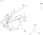
- FIG. 1 is a view illustrating an example of a heat-up display according to the present embodiment
- FIG. 2 is a view for explaining arrangement angles of components of the example of the heat-up display according to the present embodiment
- FIG. 3 is a view illustrating a first virtual image and a second virtual image, which are generated by the example of the head-up display according to the present embodiment.
- a head-up display illustrated in FIGS. 1 to 3 may comprise a housing 1, an imaging device 2, an inner mirror 3, a polarization film 4, and a phase delay mirror 5.
- the head-up display HUD may be disposed on a vehicle's instrument panel (IP) to emit light toward a vehicle's windshield WS, the driver may recognize a virtual image disposed in front of the windshield WS, and the head-up display HUD may display a variety of information comprising driving information while the vehicle is driving.
- IP vehicle's instrument panel
- the windshield WS may be configured to protect the driver and ensure visibility at a front surface of the vehicle and may reflect light from the head-up display HUD to the driver's eyes eyebox.
- the driver's eyes eyebox may be defined as an area on which light from the head-up display HUD is focused.
- the housing 1 may be disposed at a lower side of the windshield WS.
- An inner space IS may be defined inside the housing 1.
- the housing 1 may have an opening 11 defined in an upper portion thereof.
- the housing 1 may be provided as a single member or may be provided as a combination of multiple members.
- the housing 1 may comprise a lower housing 12, in which the inner space IS is defined, and a top surface thereof is opened, and an upper cover 13 disposed on a top surface of the lower housing 11 and having an opening 11.
- a blind loop 15 on which a phase delay mirror 5 is disposed may be provided at an upper portion of the housing 1.
- the blind loop 15 may be disposed outside the inner space IS.
- the blind loop 15 may protect the phase delay mirror 5 from the outside of the housing 1.
- the blind loop 15 may be a mirror bench on which the phase delay mirror 5 is mounted.
- the blind loop 15 may comprise a main blind part 16 on which a phase delay mirror 5 is disposed on a rear surface, and a sub-blind part 17 protruding backward from an upper end of the main blind part 16.
- the blind loop 15 may constitute a blind loop assembly 18 together with the phase delay mirror 5, and the blind loop assembly 18 may be disposed between a light trap 19 of the vehicle and the housing 1.
- An example of the blind loop assembly 18 may be disposed on the upper portion of the housing 1 to constitute a portion of the head-up display HUD.
- the blind loop assembly 18 may be spaced apart from the light trap 19.
- blind loop assembly 18 may be comprised in a configuration of the light trap 19 and may not be comprised in the head-up display HUD.
- the imaging device 2 may be accommodated in the inner space IS.
- the imaging device 2 may emit first linearly polarized light in a first direction.
- An example of the imaging device 2 may comprise a display panel that emits image light and a linear polarizer that linearly polarizes the image light emitted from the display panel into the first linearly polarized light in the first direction.
- the display panel may realize all types of on-screen pixel display manners, and the display panel may emit the image light toward the linear polarizer.
- Examples of the display panel may comprise a liquid crystal display (LCD) panels, an organic light emitting diode (OLED) panel, a DLP, an L-cos, a micro LED, a BLU, etc.
- the linear polarizer may be installed inside or outside the display panel.
- the linear polarizer may only pass the linearly polarized light in the first direction of the image light emitted from the display panel. Non-polarized light may be emitted from the display panel, and the non-polarized light may be polarized in the first direction by the linear polarizer. In the linear polarizer, P-wave linearly polarized light P or S-wave linearly polarized light S may be emitted.
- the imaging device 2 may selectively emit the P-wave linearly polarized light P or the S-wave linearly polarized light S depending on the system configuration.
- the first linearly polarized light emitted from the imaging device 2 is the P-wave linearly polarized light P
- the second linearly polarized light is the S-wave linearly polarized light S
- the reverse case may be also applicable.
- the imaging device 2 may be disposed at an upper portion ISU of the inner space IS.
- the imaging device 2 may comprise an emission surface 21 through which the first linearly polarized light P is emitted.
- the imaging device 2 may be disposed to be inclined in the inner space IS.
- the imaging device 2 may be disposed so that the emission surface 21 faces an inclined direction FL at a front lower side as illustrated in FIG. 2 .
- the imaging device 2 may not be aligned with each of the inner mirror 3, the polarization film 4, and the phase delay mirror 5.
- the imaging device 2 may not be aligned with each of the first inner mirror 32, the second inner mirror 34, and the polarization film. 4 and the phase delay mirror 5.
- the emission surface 21 may face a reflective surface 31 of the inner mirror 3.
- the first linearly polarized light P emitted from the emission surface 21 may be incident into the reflective surface 31 of the inner mirror 3.
- the imaging device 2 may be disposed below the polarization film 4 so as to be spaced apart from the polarization film 4 in a vertical direction Z.
- the imaging device 2 may be protected by the housing 1 and the polarization film 4.
- the inner mirror 3 may reflect the first linearly polarized light P in the first direction, which is emitted from the imaging device 2.
- the inner mirror 3 may be disposed so that the reflective surface 31 of the inner mirror 3 faces approximately the rear upper direction RU.
- the inner mirror 3 may be disposed to be spaced apart from the imaging device 2 in the inner space IS.
- the inner mirror 3 may be disposed below the polarization film 4 so as to be spaced apart from the polarization film 4 in the vertical direction Z. As illustrated in FIG. 1 , the inner mirror 3 may be disposed at a lower portion ISL of the inner space IS.
- the inner mirror 3 may be a single inner mirror or may be a plurality of inner mirrors.
- An example of the inner mirror 3 may comprise a first inner mirror 32 and a second inner mirror 34.
- the first inner mirror 32 may be disposed to be spaced apart from the imaging device 1.
- the first inner mirror 32 may reflect the first linearly polarized light emitted from the imaging device 1.
- the first inner mirror 32 may be disposed to reflect the first linearly polarized light P toward the phase delay mirror 5.
- the first inner mirror 32 may be disposed to reflect the first linearly polarized light P toward the second inner mirror 34.
- a portion of the first linearly polarized light P reflected from the first inner mirror 32 may be directed toward the phase delay mirror 5, and the remaining portion of the first linearly polarized light P reflected from the first inner mirror 32 may be directed to the second inner mirror 34.
- the first inner mirror 32 may have a reflective surface 31 disposed on a top surface thereof.
- the first inner mirror 32 may be disposed to be inclined at a predetermined angle in the inner space IS.
- the first inner mirror 32 may be disposed closer to a horizontal plane than to a vertical plane.
- the first inner mirror 32 may be a flat mirror or a curved mirror.
- the first inner mirror 32 may change and converge an optical path of a first virtual image FI1 (see FIG. 3 ) and may be disposed below the polarization film 4 in the vertical direction Z.
- the second inner mirror 34 may be disposed to be spaced apart from the imaging device 1.
- the second inner mirror 34 may reflect (i.e., re-reflect) the first linearly polarized light P reflected from the first inner mirror 32.
- the second inner mirror 34 may be disposed to reflect the first linearly polarized light P toward the windshield W.
- the second inner mirror 34 may have a reflective surface 31 disposed on a rear surface thereof.
- the second inner mirror 34 may be disposed to be inclined at a predetermined angle or vertically in the inner space IS. When the second inner mirror 34 is disposed to be inclined, the second inner mirror 34 may be disposed closer to the vertical plane than to the horizontal plane.
- the second inner mirror 34 may be a flat mirror or a curved mirror.
- the second inner mirror 34 may change and converge an optical path of the second virtual image FI2 (see FIG. 3 ) and may be disposed below the polarization film 4 in the vertical direction Z.
- the second inner mirror 34 may not reflect the first linearly polarized light P toward the phase delay mirror 5, but reflect the first linearly polarized light P toward an empty space OS behind the phase delay mirror 5.
- the first linearly polarized light P reflected toward the empty space OS behind the phase delay mirror 5 may not be reflected by the phase delay mirror 5 and may be directed toward the windshield WS.
- a first extension line E1 extending from the first inner mirror 32 and a second extension line E2 extending from the second inner mirror 34 may be intersected at a first inclination angle ⁇ 1, and the first inclination angle ⁇ 1 may be an obtuse angle.
- the first extension line E1 may extend from the first inner mirror 32 in the longitudinal direction of the first inner mirror 32.
- the second extension line E2 may extend from the second inner mirror 34 in a longitudinal direction of the second inner mirror 34.
- the second extension line E2 extending downward from the second inner mirror 34 and the first extension line E1 extending in the inclined direction of the front upper side from the first inner mirror 32 may be intersected at the first inclination angle ⁇ 1.
- the second extension line E2 extending from the second inner mirror 34 and the third extension line E3 extending from the phase delay mirror 5 may be intersected at a second inclination angle ⁇ 2, and the second inclination angle ⁇ 2 may be an obtuse angle.
- the second extension line E2 may extend from the second inner mirror 34 in a longitudinal direction of the second inner mirror 34.
- the third extension line E3 may extend from the phase delay mirror 5 in the longitudinal direction of the phase delay mirror 5.
- the second extension line E2 extending upward from the second inner mirror 34 and the third extension line E3 extending in the inclined direction toward the front lower side from the phase delay mirror 5 may be intersected at the second inclination angle ⁇ 2.
- the head-up display HUD may display only the first inner mirror 32 without the second inner mirror 34.
- the second inner mirror 34 may be installed in addition to the first inner mirror 32 to add a virtual image.
- the polarization film 4 may transmit the first linearly polarized light P reflected from the inner mirror 3 and reflect the second linearly polarized light S in the second direction that is orthogonal to the first direction.
- the polarization film 4 may be a reflective polarizer or a reflective polarization film.
- the polarization film 4 may have a flat or cylindrical shape and may also have a spherical or aspherical shape.
- the polarization film 4 may cover the inner space IS.
- the polarization film 4 may be disposed in the opening 11 of the housing 1.
- the polarization film 4 may be a cover dust that prevents foreign substances such as dust from penetrated through the opening 11.
- An example of the polarization film 4 may have a continuous surface divided into two or more surfaces to prevent external light from being penetrated.
- the polarization film 4 may have a first surface defined on a side surface and a second surface defined on a front surface, and the first and second surfaces may be continuous surfaces.
- a blind cover made of light-absorbing material may be attached to a lower end of the polarization film 4 to minimize the penetration of the external light into the head-up display HUD.
- the polarization film 4 may partition an empty space OS disposed behind the phase delay mirror 5 and an inner space 1S.
- the empty space OS disposed behind the phase delay mirror 5 may be defined as an outer space OS.
- the polarization film 4 may be disposed between the phase delay mirror 5 and the first inner mirror 32.
- the polarization film 4 may be disposed between the phase delay mirror 5 and the second inner mirror 34.
- the polarization film 4 may be disposed between the windshield WS and the imaging device 2.
- the polarization film 4 may comprise a front area 41 disposed between the first inner mirror 32 and the phase delay mirror 5 in the vertical direction Z.
- the polarization film 4 may comprise a rear area 42 disposed between the imaging device 2 and the windshield WS in the vertical direction Z.
- the polarization film 4 may comprise an intermediate area 43 that is disposed between the front area 41 and the rear area 42 to face the lower portion of the housing 1 in the vertical direction Z.
- the polarization film 4 may intersect a fourth extension line E4 extending from the imaging device 2.
- the fourth extension line E4 extending from the imaging device 2 and the polarization film 4 may be intersected at a third inclination angle ⁇ 3, and the third inclination angle ⁇ 3 may be an acute angle.
- the fourth extension line E4 may extend from the imaging device 2 in the longitudinal direction of the imaging device 2.
- the phase delay mirror 5 may be disposed outside the inner space IS.
- the phase delay mirror 5 may be disposed above the polarization film 4.
- the phase delay mirror 5 may be disposed to be inclined.
- the phase delay mirror 5 may phase convert the first linearly polarized light P, which is reflected from the inner mirror 3 and transmitted through the reflective polarization film 4, into second linearly polarized light S to reflect the second linearly polarized light S to the polarization film 4.
- the phase delay mirror 5 may be disposed outside the inner space IS.
- the phase delay mirror 5 may be disposed above the inner space IS.
- the phase delay mirror 5 may delay a phase of the linearly polarized light P emitted from the imaging device 2, and a front surface of the phase delay mirror 5 may be configured to block the external light.
- the phase delay mirror 5 may comprise a phase retarder and an outer mirror 54.
- the phase retarder may be a 1/4 wavelength phase retarder 52.
- the 1/4 wavelength phase retarder 52 may be disposed outside the inner space IS.
- the 1/4 wavelength phase retarder 52 may be directed toward the polarization film 4.
- a rear surface of the 1/4 wavelength phase retarder 52 may face an inclined direction RL (see FIG. 2 ) that is directed toward a rear lower side.
- the outer mirror 54 may be disposed in front of the 1/4 wavelength phase retarder 52.
- the outer mirror 54 may comprise a reflective surface 55 that reflects light.
- the reflective surface 55 may be a surface of both sides of the outer mirror 54, which faces the 1/4 wavelength phase retarder 52.
- the outer mirror 54 may be disposed to be inclined at a predetermined angle.
- the reflective surface 55 may face the inclined direction RL that is directed to the rear lower side.
- the first linearly polarized light P (see FIG. 1 ) reflected from the inner mirror 3, especially the second inner mirror 34, may pass through the polarization film 4 to pass through the space OS defined behind the phase delay mirror 5 so as to proceed to the windshield W.
- the second linearly polarized light S (see FIG. 1 ) emitted from the phase delay mirror 5 may be reflected to the windshield WS by the polarization film 4.
- the head-up display may comprise two optical paths.
- the first optical path may successively lead to the imaging device 2, the first inner mirror 32, the polarization film 4, the 1/4 wavelength phase retarder 52, the outer mirror 54, the 1/4 wavelength phase retardant 52, the polarization film 4, and the windshield WS, and the second linearly polarized light S may be incident into the windshield WS.
- the second optical path may successively lead to the imaging device 2, the first inner mirror 32, the second inner mirror 34, the polarization film 4, and the windshield WS, and the first linearly polarized light P may be incident into the windshield WS.
- a first virtual image FI1 may be generated by the first optical path, and a second virtual image FI2 may be generated by the second optical path.
- a length of the first optical path may be longer than that of the second optical path.
- the first virtual image FI1 may perform a largescreen AR function at a long distance, and the second virtual image FI2 may perform information transfer at a short distance.
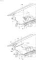
- FIG. 4 is a view illustrating a comparative example of the heat-up display according to the present embodiment
- a polarization reflection mirror 4' may be accommodated in an inner space IS of a housing 1', an imaging device 2' may be disposed at a front lower side or below the polarizing reflection mirror 4', a first reflection mirror 6' that reflects light emitted from the polarization reflection mirror 4' to a windshield WS may be disposed in front of the polarization reflection mirror 4', and a second reflection mirror 6' may be disposed behind the polarization reflection mirror 4'.
- the housing 1' may accommodate the polarization reflection mirror 4' and both the first reflection mirror 6' and the second reflection mirror 6', and thus, an inner space IS having a large volume may be required.
- the space disposed at an upper side of the housing 1 may be defined as an outer space OS, and Table 1 shows results obtained by comparing a volume according to the comparative example to a volume according to the present example.
- Table 1 Comparative example The present embodiment Reduction rate OS Volume 5L 5L IS Volume 15.5L 9L -42% Total volume 20.5L 14L -32%
- FIG. 5 is a view illustrating a first modified example of the heat-up display according to the present embodiment.
- the head-up display HUD illustrated in FIG. 5 may have an inner mirror 3' different from the configuration of the inner mirror 3 illustrated in FIGS. 1 to 3 .
- the second inner mirror 34' may reflect the first linearly polarized light P emitted from the imaging device 2.
- a first inner mirror 32' may be disposed to be spaced apart from the imaging device 2 to reflect a portion Pa of the first linearly polarized light P emitted from the imaging device 2.
- the second inner mirror 34' may be disposed to be spaced apart from the imaging device 2 to reflect the remaining portion Pb of the first linearly polarized light P emitted from the imaging device 2.
- the portion Pa of the first linearly polarized light P reflected from the second inner mirror 34' may pass through the polarization film 4 and then be converted into the second linearly polarized light S by the phase delay mirror 5.
- the second linearly polarized light S may be reflected to the windshield WS by the polarization film 4.
- the remaining portion Pb of the first linearly polarized light P reflected from the second inner mirror 34' may pass through the empty space OS behind the phase delay mirror 5 to proceed to the windshield WS.
- the head-up display HUD may further comprise a blind 24 accommodated in the inner space IS.
- the blind 24 may be disposed to be approximately orthogonal to the imaging device 2 and may guide the portion Pa of the first linearly polarized light P emitted from the imaging device 2 to the first inner mirror 32' and may guide the remaining portion Pb of the first linearly polarized light P emitted from the imaging device 2 to the second inner mirror 34'.
- a configuration and operation of the housing 1, the imaging device 2, the polarizing film 4, and the phase retardation mirror 5 other than the first inner mirror 32' and the second inner mirror 34' may be the same as or similar to an example of the head-up display illustrated in FIGS. 1 to 3 , and to avoid duplicated description, the same symbols may be used, and detailed descriptions thereof will be omitted.
- the head-up display HUD may have a first optical path and a second optical path.
- the first optical path may successively lead to the imaging device 2, the first inner mirror 32', the polarization film 4, the 1/4 wavelength phase retarder 52, the outer mirror 54, the 1/4 wavelength phase retardant 54, the polarization film 4, and the windshield WS, and a first virtual image may be implemented.
- the second optical path may lead to the imaging device 2, the second inner mirror 34', the polarization film 4, and the windshield WS, and a second virtual image may be implemented.
- FIG. 6 is a view illustrating a second modified example of the heat-up display according to the present embodiment
- FIG. 7 is a view when the second modified example of the head-up display illustrated in FIG. 6 implements only a first virtual image.
- the head-up display illustrated in FIG. 6 may be provided with one inner mirror 3", and a configuration and operation of the housing 1, the imaging device 2, the polarizing film 4, and the phase retardation mirror 5 other than one inner mirror 3" may be the same as or similar to an example of the head-up display illustrated in FIG. 5 , and to avoid duplicated description, the same symbols may be used, and detailed descriptions thereof will be omitted.
- the inner mirror 3" illustrated in FIG. 6 may comprise a first inner mirror portion 32" and a second inner mirror portion 34", and the first inner mirror portion 32" and a second inner mirror portion 34" may be integrated with each other.
- the first inner mirror portion 32" and the second inner mirror portion 34" may have an obtuse inclination angle ⁇ 4.
- the first inner mirror portion 32" may reflect a portion PA of the first linearly polarized light P emitted from the imaging device 2 to the phase delay mirror 5.
- the second inner mirror portion 34" may reflect the remaining portion Pb of the first linearly polarized light P emitted from the imaging device 2 to the windshield WS.
- the inner mirror 3" illustrated in FIG. 6 may be a curved mirror having a curved overall shape.
- a lower portion of the curved mirror may be the first inner mirror portion 32", and an upper portion of the curved mirror may be the second inner mirror portion 34".
- the inner mirror 3" may comprise a connecting mirror portion 36" connecting the first inner mirror portion 32" to the second inner mirror portion 34".
- a first extension line extending from the first inner mirror portion 32" and a second extension line extending from the second inner mirror portion 34" may be intersected at a first inclination angle ⁇ 1, and the first inclination angle ⁇ 1 may be an obtuse angle.
- Each of the first inner mirror portion 32" and the second inner mirror portion 34" may be provided in a flat shape or an arc shape.
- the connecting mirror portion 36" may be provided in an arc shape.
- a first virtual image and a second virtual image may be implemented together as illustrated in FIG. 6 , and only a first virtual image may be implemented as illustrated in FIG. 7 .
Landscapes
- Physics & Mathematics (AREA)
- General Physics & Mathematics (AREA)
- Optics & Photonics (AREA)
- Engineering & Computer Science (AREA)
- Chemical & Material Sciences (AREA)
- Combustion & Propulsion (AREA)
- Transportation (AREA)
- Mechanical Engineering (AREA)
- Instrument Panels (AREA)
Abstract
Description
- The present invention relates to a head-up display, and more specifically, to a head-up display that is capable of being installed in a vehicle.
- A head-up display may be a device provided in a vehicle to emit image light to a windshield of the vehicle. The head up display for the vehicle may display various information comprising driving information during the driving of the vehicle.
- The head-up display comprises a display panel generating and outputting image light and at least one mirror reflecting the image light generated by the display panel.
- The image light generated by the display panel may be incident into the windshield of the vehicle by the mirror, and a driver may recognize a virtual image in the front of the windshield.
- When the head-up display comprises two image sources, two virtual images may be generated, and in this case, convenience of the head-up display for a vehicle may be improved.
- Korea Patent Publication No.
KR 10-2015-0093353 A (published on August 18, 2015 - The head-up display comprises one image source, but is capable of generating two virtual images by providing two optical paths having different total lengths of the optical paths, and a head-up display for a vehicle, which provides two optical paths using one image source, is disclosed in
Korean Patent Publication No. 10-1909374 B1 (published on October 17, 2018 - The head-up display for the vehicle comprises: an image source that emits linearly polarized light in a first direction; a prism that refracts some of the linearly polarized light emitted from the image source; an electric polarization conversion element that transmits others of the linearly polarized light emitted from the image source when turned off, and converts others of the linearly polarized light emitted from the image source into linearly polarized light in a second direction perpendicular to the first direction by a half-wavelength when turned on; a first reflection mirror that reflects light to a windshield of the vehicle; a polarization reflection mirror disposed to be spaced apart from the first reflection mirror, reflecting the linearly polarized light in a first direction, and transmitting the linearly polarized light in a second direction; and a second reflection mirror disposed to be spaced apart from the polarization reflection mirror and reflecting the light transmitted through the polarization reflection mirror to the polarization reflection mirror, and the second reflection mirror comprises a flat mirror disposed to face the polarization reflection mirror.
- An object of the present invention is to provide a head-up display that is capable of being compacted by minimizing a height and width.
- A head-up display according to the present embodiment may comprise: a housing having an inner space therein and disposed below a windshield; an imaging device which is accommodated in the inner space and emits first linearly polarized light in a first direction; an inner mirror which is disposed to be spaced apart from the imaging device in the inner space and is configured to reflect the first linearly polarized light emitted from the imaging device in the first direction; a polarization film configured to transmit the first linearly polarized light reflected from the inner mirror and reflect second linearly polarized light in a second direction orthogonal to the first direction; and a phase delay mirror which is disposed outside the inner space and is configured to phase-convert the first linearly polarized light transmitted through the polarization film after being reflected from the inner mirror into the second linearly polarized light so as to emit the second linearly polarized light to the polarization film. The second linearly polarized light emitted from the phase delay mirror may be reflected to the windshield by the polarization film. The first linearly polarized light reflected from the inner mirror may be transmitted through the polarization film to proceed to the windshield.
- The phase delay mirror may comprise: a 1/4 wavelength phase retarder disposed outside the inner space and facing the polarization film; and an outer mirror disposed in front of the 1/4 wavelength phase retarder.
- The inner mirror may comprise: a first inner mirror configured to reflect the first linearly polarized light emitted from the imaging device; and a second inner mirror disposed to be spaced apart from the imaging device so as to reflect the first linearly polarized light reflected from the first inner mirror or reflect the first linearly polarized light emitted from the imaging device.
- A first optical path may be provided by the imaging device, the first inner mirror, the polarization film, the 1/4 wavelength phase retarder, the outer mirror, the 1/4 wavelength phase retarder, the polarization film, and the windshield, which are successively connected to each other.
- One example of a second optical path may be provided by the imaging device, the first inner mirror, the second inner mirror, the polarization film, and the windshield, which are successively connected to each other.
- The other example of the second optical path may be provided by the imaging device, the second inner mirror, the polarization film, and the windshield, which are successively connected to each other.
- The first inner mirror may be disposed to reflect the first linearly polarized light toward the phase delay mirror. The polarization film may be disposed between the phase delay mirror and the first inner mirror.
- The second inner mirror may be disposed to reflect the first linearly polarized light toward the windshield. The polarization film may be disposed between the phase delay mirror and the first inner mirror.
- The imaging device may not aligned with each of the first inner mirror, the second inner mirror, the polarization film, and the phase delay mirror.
- A first extension line extending from the first inner mirror and a second extension line extending from the second inner mirror may be intersected at a first inclination angle, and the first inclination angle may be an obtuse angle.
- The second extension line and a third extension line extending from the phase delay mirror may be intersected at a second inclination angle, and the second inclination angle may be an obtuse angle.
- A fourth extension line extending from the imaging device and the polarization film may be intersected at a third inclination angle. The third inclination angle may be an acute angle.
- The imaging device may be disposed to be spaced apart from the polarization film in a vertical direction below the polarization film.
- The inner mirror may be disposed to be spaced apart from the polarization film in a vertical direction below the polarization film.
- The phase delay mirror may be disposed above the polarization film.
- The polarization film may be configured to cover the inner space.
- A blind loop on which the phase delay mirror may be disposed is provided at an upper portion of the housing.
- A modified example of the inner mirror may comprise: a first inner mirror portion configured to reflect a portion of the first linearly polarized light emitted from the imaging device to the phase delay mirror; and a second inner mirror portion configured to reflect the other potion of the first linearly polarized light emitted from the imaging device to the windshield, wherein the first inner mirror portion and the second inner mirror portion may be integrated with each other and have an obtuse inclination angle.
- According to the embodiment of the present invention, since the phase delay mirror is disposed outside the inner space of the housing, the volume of the inner space and the volume of the housing may be minimized to compact the head-up display.
- In addition, since the polarization film covers the inner space of the housing to prevent the foreign substances from being penetrated, a separate cover to cover the inner space of the housing may be unnecessary, the number of components may be minimized, and the structure may be simplified.
-
-
FIG. 1 is a view illustrating an example of a heat-up display according to the present embodiment, -
FIG. 2 is a view for explaining arrangement angles of components of the example of the heat-up display according to the present embodiment, -
FIG. 3 is a view illustrating a first virtual image and a second virtual image, which are generated by the example of the head-up display according to the present embodiment, -
FIG. 4 is a view illustrating a comparative example of the heat-up display according to the present embodiment, -
FIG. 5 is a view illustrating a first modified example of the heat-up display according to the present embodiment, -
FIG. 6 is a view illustrating a second modified example of the heat-up display according to the present embodiment, and -
FIG. 7 is a view when the second modified example of the head-up display illustrated inFIG. 6 implements only a first virtual image. - Hereinafter, detailed embodiments will be described in detail with reference to the accompanying drawings.
-
FIG. 1 is a view illustrating an example of a heat-up display according to the present embodiment,FIG. 2 is a view for explaining arrangement angles of components of the example of the heat-up display according to the present embodiment, andFIG. 3 is a view illustrating a first virtual image and a second virtual image, which are generated by the example of the head-up display according to the present embodiment. - A head-up display illustrated in
FIGS. 1 to 3 may comprise ahousing 1, animaging device 2, aninner mirror 3, apolarization film 4, and aphase delay mirror 5. - The head-up display HUD may be disposed on a vehicle's instrument panel (IP) to emit light toward a vehicle's windshield WS, the driver may recognize a virtual image disposed in front of the windshield WS, and the head-up display HUD may display a variety of information comprising driving information while the vehicle is driving.
- The windshield WS may be configured to protect the driver and ensure visibility at a front surface of the vehicle and may reflect light from the head-up display HUD to the driver's eyes eyebox. The driver's eyes eyebox may be defined as an area on which light from the head-up display HUD is focused.
- The
housing 1 may be disposed at a lower side of the windshield WS. An inner space IS may be defined inside thehousing 1. Thehousing 1 may have anopening 11 defined in an upper portion thereof. - The
housing 1 may be provided as a single member or may be provided as a combination of multiple members. Thehousing 1 may comprise alower housing 12, in which the inner space IS is defined, and a top surface thereof is opened, and anupper cover 13 disposed on a top surface of thelower housing 11 and having anopening 11. - A
blind loop 15 on which aphase delay mirror 5 is disposed may be provided at an upper portion of thehousing 1. Theblind loop 15 may be disposed outside the inner space IS. Theblind loop 15 may protect thephase delay mirror 5 from the outside of thehousing 1. - The
blind loop 15 may be a mirror bench on which thephase delay mirror 5 is mounted. - The
blind loop 15 may comprise a mainblind part 16 on which aphase delay mirror 5 is disposed on a rear surface, and asub-blind part 17 protruding backward from an upper end of the mainblind part 16. - The
blind loop 15 may constitute ablind loop assembly 18 together with thephase delay mirror 5, and theblind loop assembly 18 may be disposed between alight trap 19 of the vehicle and thehousing 1. - An example of the
blind loop assembly 18 may be disposed on the upper portion of thehousing 1 to constitute a portion of the head-up display HUD. Theblind loop assembly 18 may be spaced apart from thelight trap 19. - Another example of the
blind loop assembly 18 may be comprised in a configuration of thelight trap 19 and may not be comprised in the head-up display HUD. - The
imaging device 2 may be accommodated in the inner space IS. Theimaging device 2 may emit first linearly polarized light in a first direction. - An example of the
imaging device 2 may comprise a display panel that emits image light and a linear polarizer that linearly polarizes the image light emitted from the display panel into the first linearly polarized light in the first direction. - The display panel may realize all types of on-screen pixel display manners, and the display panel may emit the image light toward the linear polarizer. Examples of the display panel may comprise a liquid crystal display (LCD) panels, an organic light emitting diode (OLED) panel, a DLP, an L-cos, a micro LED, a BLU, etc.
- The linear polarizer may be installed inside or outside the display panel.
- The linear polarizer may only pass the linearly polarized light in the first direction of the image light emitted from the display panel. Non-polarized light may be emitted from the display panel, and the non-polarized light may be polarized in the first direction by the linear polarizer. In the linear polarizer, P-wave linearly polarized light P or S-wave linearly polarized light S may be emitted.
- The
imaging device 2 may selectively emit the P-wave linearly polarized light P or the S-wave linearly polarized light S depending on the system configuration. - Hereinafter, for convenience of explanation, an example in which the first linearly polarized light emitted from the
imaging device 2 is the P-wave linearly polarized light P, and the second linearly polarized light is the S-wave linearly polarized light S will be described, but the reverse case may be also applicable. - The
imaging device 2 may be disposed at an upper portion ISU of the inner space IS. Theimaging device 2 may comprise anemission surface 21 through which the first linearly polarized light P is emitted. - The
imaging device 2 may be disposed to be inclined in the inner space IS. Theimaging device 2 may be disposed so that theemission surface 21 faces an inclined direction FL at a front lower side as illustrated inFIG. 2 . - The
imaging device 2 may not be aligned with each of theinner mirror 3, thepolarization film 4, and thephase delay mirror 5. - When the
inner mirror 3 comprises a firstinner mirror 32 and a secondinner mirror 34, theimaging device 2 may not be aligned with each of the firstinner mirror 32, the secondinner mirror 34, and the polarization film. 4 and thephase delay mirror 5. - The
emission surface 21 may face areflective surface 31 of theinner mirror 3. The first linearly polarized light P emitted from theemission surface 21 may be incident into thereflective surface 31 of theinner mirror 3. - The
imaging device 2 may be disposed below thepolarization film 4 so as to be spaced apart from thepolarization film 4 in a vertical direction Z. Theimaging device 2 may be protected by thehousing 1 and thepolarization film 4. - The
inner mirror 3 may reflect the first linearly polarized light P in the first direction, which is emitted from theimaging device 2. Theinner mirror 3 may be disposed so that thereflective surface 31 of theinner mirror 3 faces approximately the rear upper direction RU. - The
inner mirror 3 may be disposed to be spaced apart from theimaging device 2 in the inner space IS. Theinner mirror 3 may be disposed below thepolarization film 4 so as to be spaced apart from thepolarization film 4 in the vertical direction Z. As illustrated inFIG. 1 , theinner mirror 3 may be disposed at a lower portion ISL of the inner space IS. - The
inner mirror 3 may be a single inner mirror or may be a plurality of inner mirrors. An example of theinner mirror 3 may comprise a firstinner mirror 32 and a secondinner mirror 34. - The first
inner mirror 32 may be disposed to be spaced apart from theimaging device 1. The firstinner mirror 32 may reflect the first linearly polarized light emitted from theimaging device 1. - The first
inner mirror 32 may be disposed to reflect the first linearly polarized light P toward thephase delay mirror 5. The firstinner mirror 32 may be disposed to reflect the first linearly polarized light P toward the secondinner mirror 34. - A portion of the first linearly polarized light P reflected from the first
inner mirror 32 may be directed toward thephase delay mirror 5, and the remaining portion of the first linearly polarized light P reflected from the firstinner mirror 32 may be directed to the secondinner mirror 34. - The first
inner mirror 32 may have areflective surface 31 disposed on a top surface thereof. The firstinner mirror 32 may be disposed to be inclined at a predetermined angle in the inner space IS. The firstinner mirror 32 may be disposed closer to a horizontal plane than to a vertical plane. - The first
inner mirror 32 may be a flat mirror or a curved mirror. - The first
inner mirror 32 may change and converge an optical path of a first virtual image FI1 (seeFIG. 3 ) and may be disposed below thepolarization film 4 in the vertical direction Z. - The second
inner mirror 34 may be disposed to be spaced apart from theimaging device 1. The secondinner mirror 34 may reflect (i.e., re-reflect) the first linearly polarized light P reflected from the firstinner mirror 32. The secondinner mirror 34 may be disposed to reflect the first linearly polarized light P toward the windshield W. The secondinner mirror 34 may have areflective surface 31 disposed on a rear surface thereof. The secondinner mirror 34 may be disposed to be inclined at a predetermined angle or vertically in the inner space IS. When the secondinner mirror 34 is disposed to be inclined, the secondinner mirror 34 may be disposed closer to the vertical plane than to the horizontal plane. - The second
inner mirror 34 may be a flat mirror or a curved mirror. - The second
inner mirror 34 may change and converge an optical path of the second virtual image FI2 (seeFIG. 3 ) and may be disposed below thepolarization film 4 in the vertical direction Z. - The second
inner mirror 34 may not reflect the first linearly polarized light P toward thephase delay mirror 5, but reflect the first linearly polarized light P toward an empty space OS behind thephase delay mirror 5. The first linearly polarized light P reflected toward the empty space OS behind thephase delay mirror 5 may not be reflected by thephase delay mirror 5 and may be directed toward the windshield WS. - Referring to
FIG. 2 , a first extension line E1 extending from the firstinner mirror 32 and a second extension line E2 extending from the secondinner mirror 34 may be intersected at a first inclination angle Θ1, and the first inclination angle Θ1 may be an obtuse angle. The first extension line E1 may extend from the firstinner mirror 32 in the longitudinal direction of the firstinner mirror 32. The second extension line E2 may extend from the secondinner mirror 34 in a longitudinal direction of the secondinner mirror 34. The second extension line E2 extending downward from the secondinner mirror 34 and the first extension line E1 extending in the inclined direction of the front upper side from the firstinner mirror 32 may be intersected at the first inclination angle Θ1. - The second extension line E2 extending from the second
inner mirror 34 and the third extension line E3 extending from thephase delay mirror 5 may be intersected at a second inclination angle θ2, and the second inclination angle θ2 may be an obtuse angle. The second extension line E2 may extend from the secondinner mirror 34 in a longitudinal direction of the secondinner mirror 34. The third extension line E3 may extend from thephase delay mirror 5 in the longitudinal direction of thephase delay mirror 5. The second extension line E2 extending upward from the secondinner mirror 34 and the third extension line E3 extending in the inclined direction toward the front lower side from thephase delay mirror 5 may be intersected at the second inclination angle θ2. - When the
inner mirror 3 generates only the first virtual image FI1 and does not generate the second virtual image FI2, the head-up display HUD may display only the firstinner mirror 32 without the secondinner mirror 34. - The second
inner mirror 34 may be installed in addition to the firstinner mirror 32 to add a virtual image. - The
polarization film 4 may transmit the first linearly polarized light P reflected from theinner mirror 3 and reflect the second linearly polarized light S in the second direction that is orthogonal to the first direction. - The
polarization film 4 may be a reflective polarizer or a reflective polarization film. - The
polarization film 4 may have a flat or cylindrical shape and may also have a spherical or aspherical shape. - The
polarization film 4 may cover the inner space IS. Thepolarization film 4 may be disposed in theopening 11 of thehousing 1. Thepolarization film 4 may be a cover dust that prevents foreign substances such as dust from penetrated through theopening 11. - An example of the
polarization film 4 may have a continuous surface divided into two or more surfaces to prevent external light from being penetrated. Thepolarization film 4 may have a first surface defined on a side surface and a second surface defined on a front surface, and the first and second surfaces may be continuous surfaces. - A blind cover made of light-absorbing material may be attached to a lower end of the
polarization film 4 to minimize the penetration of the external light into the head-up display HUD. - The
polarization film 4 may partition an empty space OS disposed behind thephase delay mirror 5 and an inner space 1S. - The empty space OS disposed behind the
phase delay mirror 5 may be defined as an outer space OS. - The
polarization film 4 may be disposed between thephase delay mirror 5 and the firstinner mirror 32. Thepolarization film 4 may be disposed between thephase delay mirror 5 and the secondinner mirror 34. Thepolarization film 4 may be disposed between the windshield WS and theimaging device 2. - As illustrated in
FIG. 2 , thepolarization film 4 may comprise afront area 41 disposed between the firstinner mirror 32 and thephase delay mirror 5 in the vertical direction Z. Thepolarization film 4 may comprise arear area 42 disposed between theimaging device 2 and the windshield WS in the vertical direction Z. Thepolarization film 4 may comprise anintermediate area 43 that is disposed between thefront area 41 and therear area 42 to face the lower portion of thehousing 1 in the vertical direction Z. - The
polarization film 4 may intersect a fourth extension line E4 extending from theimaging device 2. The fourth extension line E4 extending from theimaging device 2 and thepolarization film 4 may be intersected at a third inclination angle θ3, and the third inclination angle θ3 may be an acute angle. - The fourth extension line E4 may extend from the
imaging device 2 in the longitudinal direction of theimaging device 2. - The
phase delay mirror 5 may be disposed outside the inner space IS. Thephase delay mirror 5 may be disposed above thepolarization film 4. Thephase delay mirror 5 may be disposed to be inclined. - The
phase delay mirror 5 may phase convert the first linearly polarized light P, which is reflected from theinner mirror 3 and transmitted through thereflective polarization film 4, into second linearly polarized light S to reflect the second linearly polarized light S to thepolarization film 4. - The
phase delay mirror 5 may be disposed outside the inner space IS. Thephase delay mirror 5 may be disposed above the inner space IS. - The
phase delay mirror 5 may delay a phase of the linearly polarized light P emitted from theimaging device 2, and a front surface of thephase delay mirror 5 may be configured to block the external light. - The
phase delay mirror 5 may comprise a phase retarder and anouter mirror 54. - The phase retarder may be a 1/4
wavelength phase retarder 52. - The 1/4
wavelength phase retarder 52 may be disposed outside the inner space IS. The 1/4wavelength phase retarder 52 may be directed toward thepolarization film 4. A rear surface of the 1/4wavelength phase retarder 52 may face an inclined direction RL (seeFIG. 2 ) that is directed toward a rear lower side. - The
outer mirror 54 may be disposed in front of the 1/4wavelength phase retarder 52. - The
outer mirror 54 may comprise a reflective surface 55 that reflects light. The reflective surface 55 may be a surface of both sides of theouter mirror 54, which faces the 1/4wavelength phase retarder 52. - The
outer mirror 54 may be disposed to be inclined at a predetermined angle. The reflective surface 55 may face the inclined direction RL that is directed to the rear lower side. - In the head-up display as described above, the first linearly polarized light P (see
FIG. 1 ) reflected from theinner mirror 3, especially the secondinner mirror 34, may pass through thepolarization film 4 to pass through the space OS defined behind thephase delay mirror 5 so as to proceed to the windshield W. - In addition, the second linearly polarized light S (see
FIG. 1 ) emitted from thephase delay mirror 5 may be reflected to the windshield WS by thepolarization film 4. - The head-up display may comprise two optical paths.
- The first optical path may successively lead to the
imaging device 2, the firstinner mirror 32, thepolarization film 4, the 1/4wavelength phase retarder 52, theouter mirror 54, the 1/4wavelength phase retardant 52, thepolarization film 4, and the windshield WS, and the second linearly polarized light S may be incident into the windshield WS. - The second optical path may successively lead to the
imaging device 2, the firstinner mirror 32, the secondinner mirror 34, thepolarization film 4, and the windshield WS, and the first linearly polarized light P may be incident into the windshield WS. - A first virtual image FI1 may be generated by the first optical path, and a second virtual image FI2 may be generated by the second optical path.
- A length of the first optical path may be longer than that of the second optical path.
- The first virtual image FI1 may perform a largescreen AR function at a long distance, and the second virtual image FI2 may perform information transfer at a short distance.
-
FIG. 4 is a view illustrating a comparative example of the heat-up display according to the present embodiment, - In the comparative example illustrated in (a) of
FIG. 4 , a polarization reflection mirror 4' may be accommodated in an inner space IS of a housing 1', an imaging device 2' may be disposed at a front lower side or below the polarizing reflection mirror 4', a first reflection mirror 6' that reflects light emitted from the polarization reflection mirror 4' to a windshield WS may be disposed in front of the polarization reflection mirror 4', and a second reflection mirror 6' may be disposed behind the polarization reflection mirror 4'. - In the comparative example illustrated in (a) of
FIG. 4 , the housing 1' may accommodate the polarization reflection mirror 4' and both the first reflection mirror 6' and the second reflection mirror 6', and thus, an inner space IS having a large volume may be required. - On the other hand, in the head-up display HUD according to the present embodiment illustrated in (b) of
FIG. 4 , since aphase delay mirror 5 is disposed outside the inner space IS of thehousing 1, and thepolarization film 4 is disposed above the inner space IS of thehousing 1, sizes of the inner space IS andhousing 1 may not need to be large as in the comparative example, and a space occupied by thehousing 1 within an instrument panel IP may also be small. - In the comparative example, the space disposed at an upper side of the
housing 1 may be defined as an outer space OS, and Table 1 shows results obtained by comparing a volume according to the comparative example to a volume according to the present example.[Table 1] Comparative example The present embodiment Reduction rate OS Volume 5L 5L IS Volume 15.5L 9L -42% Total volume 20.5L 14L -32% -
FIG. 5 is a view illustrating a first modified example of the heat-up display according to the present embodiment. - The head-up display HUD illustrated in
FIG. 5 may have an inner mirror 3' different from the configuration of theinner mirror 3 illustrated inFIGS. 1 to 3 . - The second inner mirror 34' may reflect the first linearly polarized light P emitted from the
imaging device 2. - In the head up display HUD, a first inner mirror 32' may be disposed to be spaced apart from the
imaging device 2 to reflect a portion Pa of the first linearly polarized light P emitted from theimaging device 2. The second inner mirror 34' may be disposed to be spaced apart from theimaging device 2 to reflect the remaining portion Pb of the first linearly polarized light P emitted from theimaging device 2. - The portion Pa of the first linearly polarized light P reflected from the second inner mirror 34' may pass through the
polarization film 4 and then be converted into the second linearly polarized light S by thephase delay mirror 5. The second linearly polarized light S may be reflected to the windshield WS by thepolarization film 4. - The remaining portion Pb of the first linearly polarized light P reflected from the second inner mirror 34' may pass through the empty space OS behind the
phase delay mirror 5 to proceed to the windshield WS. - The head-up display HUD may further comprise a blind 24 accommodated in the inner space IS. The blind 24 may be disposed to be approximately orthogonal to the
imaging device 2 and may guide the portion Pa of the first linearly polarized light P emitted from theimaging device 2 to the first inner mirror 32' and may guide the remaining portion Pb of the first linearly polarized light P emitted from theimaging device 2 to the second inner mirror 34'. - A configuration and operation of the
housing 1, theimaging device 2, thepolarizing film 4, and thephase retardation mirror 5 other than the first inner mirror 32' and the second inner mirror 34' may be the same as or similar to an example of the head-up display illustrated inFIGS. 1 to 3 , and to avoid duplicated description, the same symbols may be used, and detailed descriptions thereof will be omitted. - The head-up display HUD may have a first optical path and a second optical path.
- The first optical path may successively lead to the
imaging device 2, the first inner mirror 32', thepolarization film 4, the 1/4wavelength phase retarder 52, theouter mirror 54, the 1/4wavelength phase retardant 54, thepolarization film 4, and the windshield WS, and a first virtual image may be implemented. - The second optical path may lead to the
imaging device 2, the second inner mirror 34', thepolarization film 4, and the windshield WS, and a second virtual image may be implemented. -
FIG. 6 is a view illustrating a second modified example of the heat-up display according to the present embodiment, andFIG. 7 is a view when the second modified example of the head-up display illustrated inFIG. 6 implements only a first virtual image. - The head-up display illustrated in
FIG. 6 may be provided with oneinner mirror 3", and a configuration and operation of thehousing 1, theimaging device 2, thepolarizing film 4, and thephase retardation mirror 5 other than oneinner mirror 3" may be the same as or similar to an example of the head-up display illustrated inFIG. 5 , and to avoid duplicated description, the same symbols may be used, and detailed descriptions thereof will be omitted. - The
inner mirror 3" illustrated inFIG. 6 may comprise a firstinner mirror portion 32" and a secondinner mirror portion 34", and the firstinner mirror portion 32" and a secondinner mirror portion 34" may be integrated with each other. The firstinner mirror portion 32" and the secondinner mirror portion 34" may have an obtuse inclination angle θ4. - Like the first
inner mirror 32 illustrated inFIG. 5 , the firstinner mirror portion 32" may reflect a portion PA of the first linearly polarized light P emitted from theimaging device 2 to thephase delay mirror 5. - Like the second
inner mirror 34 illustrated inFIG. 5 , the secondinner mirror portion 34" may reflect the remaining portion Pb of the first linearly polarized light P emitted from theimaging device 2 to the windshield WS. - The
inner mirror 3" illustrated inFIG. 6 may be a curved mirror having a curved overall shape. A lower portion of the curved mirror may be the firstinner mirror portion 32", and an upper portion of the curved mirror may be the secondinner mirror portion 34". - The
inner mirror 3" may comprise a connectingmirror portion 36" connecting the firstinner mirror portion 32" to the secondinner mirror portion 34". - A first extension line extending from the first
inner mirror portion 32" and a second extension line extending from the secondinner mirror portion 34" may be intersected at a first inclination angle Θ1, and the first inclination angle Θ1 may be an obtuse angle. - Each of the first
inner mirror portion 32" and the secondinner mirror portion 34" may be provided in a flat shape or an arc shape. - The connecting
mirror portion 36" may be provided in an arc shape. - In the second modified example of the head-up display, a first virtual image and a second virtual image may be implemented together as illustrated in
FIG. 6 , and only a first virtual image may be implemented as illustrated inFIG. 7 . - The above-disclosed subject matter is to be considered illustrative, and not restrictive, and the appended claims are intended to cover all such modifications, enhancements, and other embodiments, which fall within the true spirit and scope of the present invention.
- Thus, the embodiment of the present invention is to be considered illustrative, and not restrictive, and the technical spirit of the present invention is not limited to the foregoing embodiment.
- Therefore, the scope of the present invention is defined not by the detailed description of the invention but by the appended claims, and all differences within the scope will be construed as being comprised in the present invention.
Claims (17)
- A head-up display comprising:a housing having an inner space therein and disposed below a windshield;pan imaging device which is accommodated in the inner space and emits first linearly polarized light in a first direction;an inner mirror which is disposed to be spaced apart from the imaging device in the inner space and is configured to reflect the first linearly polarized light emitted from the imaging device in the first direction;a polarization film configured to transmit the first linearly polarized light reflected from the inner mirror and reflect second linearly polarized light in a second direction orthogonal to the first direction; anda phase delay mirror which is disposed outside the inner space and is configured to phase-convert the first linearly polarized light transmitted through the polarization film after being reflected from the inner mirror into the second linearly polarized light so as to emit the second linearly polarized light to the polarization film,wherein the second linearly polarized light emitted from the phase delay mirror is reflected to the windshield by the polarization film, andthe first linearly polarized light reflected from the inner mirror is transmitted through the polarization film to proceed to the windshield.
- The head-up display according to claim 1, wherein the phase delay mirror comprises:a 1/4 wavelength phase retarder disposed outside the inner space and facing the polarization film; andan outer mirror disposed in front of the 1/4 wavelength phase retarder.
- The head-up display according to claim 2, wherein the inner mirror comprises:a first inner mirror configured to reflect the first linearly polarized light emitted from the imaging device; anda second inner mirror disposed to be spaced apart from the imaging device so as to reflect the first linearly polarized light reflected from the first inner mirror or reflect the first linearly polarized light emitted from the imaging device.
- The head-up display according to claim 3, further comprising:
a first optical path through which the imaging device, the first inner mirror, the polarization film, the 1/4 wavelength phase retarder, the outer mirror, the 1/4 wavelength phase retarder, the polarization film, and the windshield are successively connected to each other and a second optical path through which the imaging device, the first inner mirror, the second inner mirror, the polarization film, and the windshield are successively connected to each other. - The head-up display according to claim 3, further comprising:
a first optical path through which the imaging device, the first inner mirror, the polarization film, the 1/4 wavelength phase retarder, the outer mirror, the 1/4 wavelength phase retarder, the polarization film, and the windshield are successively connected to each other and a second optical path through which the imaging device, the second inner mirror, the polarization film, and the windshield are successively connected to each other. - The head-up display according to claim 3, wherein the first inner mirror is disposed to reflect the first linearly polarized light toward the phase delay mirror, and
the polarization film is disposed between the phase delay mirror and the first inner mirror. - The head-up display according to claim 3, wherein the second inner mirror is disposed to reflect the first linearly polarized light toward the windshield, and
the polarization film is disposed between the phase delay mirror and the first inner mirror. - The head-up display according to claim 3, wherein the imaging device is not aligned with each of the first inner mirror, the second inner mirror, the polarization film, and the phase delay mirror.
- The head-up display according to claim 3, wherein a first extension line extending from the first inner mirror and a second extension line extending from the second inner mirror are intersected at a first inclination angle, and
the first inclination angle is an obtuse angle. - The head-up display according to claim 9, wherein the second extension line and a third extension line extending from the phase delay mirror are intersected at a second inclination angle, and
the second inclination angle is an obtuse angle. - The head-up display according to claim 10, wherein a fourth extension line extending from the imaging device and the polarization film are intersected at a third inclination angle, and
the third inclination angle is an acute angle. - The head-up display according to claim 1, wherein the inner mirror comprises:a first inner mirror portion configured to reflect a portion of the first linearly polarized light emitted from the imaging device to the phase delay mirror; anda second inner mirror portion configured to reflect the other potion of the first linearly polarized light emitted from the imaging device to the windshield,wherein the first inner mirror portion and the second inner mirror portion are integrated with each other and have an obtuse inclination angle.
- The head-up display according to claim 1, wherein the imaging device is disposed to be spaced apart from the polarization film in a vertical direction below the polarization film.
- The head-up display according to claim 1, wherein the inner mirror is disposed to be spaced apart from the polarization film in a vertical direction below the polarization film.
- The head-up display according to claim 1, wherein the phase delay mirror is disposed above the polarization film.
- The head-up display according to claim 1, wherein the polarization film is configured to cover the inner space.
- The head-up display according to claim 1, wherein a blind loop on which the phase delay mirror is disposed is provided at an upper portion of the housing.
Applications Claiming Priority (2)
| Application Number | Priority Date | Filing Date | Title |
|---|---|---|---|
| KR1020210125744A KR102467924B1 (en) | 2021-09-23 | 2021-09-23 | Head Up Display for Vehicle |
| PCT/KR2021/013220 WO2023048314A1 (en) | 2021-09-23 | 2021-09-28 | Head-up display |
Publications (2)
| Publication Number | Publication Date |
|---|---|
| EP4407361A1 true EP4407361A1 (en) | 2024-07-31 |
| EP4407361A4 EP4407361A4 (en) | 2025-09-10 |
Family
ID=84233251
Family Applications (1)
| Application Number | Title | Priority Date | Filing Date |
|---|---|---|---|
| EP21958491.9A Pending EP4407361A4 (en) | 2021-09-23 | 2021-09-28 | HEAD-UP DISPLAY |
Country Status (5)
| Country | Link |
|---|---|
| US (1) | US20240402491A1 (en) |
| EP (1) | EP4407361A4 (en) |
| KR (1) | KR102467924B1 (en) |
| CN (1) | CN117980797A (en) |
| WO (1) | WO2023048314A1 (en) |
Families Citing this family (3)
| Publication number | Priority date | Publication date | Assignee | Title |
|---|---|---|---|---|
| EP4617764A4 (en) * | 2022-11-23 | 2026-03-25 | Lg Electronics Inc | REDUCED VOLUME VEHICLE IMAGERATION DEVICE |
| WO2025230054A1 (en) | 2024-04-30 | 2025-11-06 | 엘지전자 주식회사 | Head-up display |
| WO2025263647A1 (en) * | 2024-06-18 | 2025-12-26 | 엘지전자 주식회사 | Imaging device for vehicle having reduced volume |
Family Cites Families (10)
| Publication number | Priority date | Publication date | Assignee | Title |
|---|---|---|---|---|
| JP6335524B2 (en) * | 2014-01-27 | 2018-05-30 | 矢崎総業株式会社 | Head-up display device |
| KR102071693B1 (en) | 2014-02-07 | 2020-01-30 | 엘지전자 주식회사 | Head-Up Display Apparatus |
| WO2015159522A1 (en) * | 2014-04-14 | 2015-10-22 | パナソニックIpマネジメント株式会社 | Heads-up display and moving body equipped with heads-up display |
| JP5930231B2 (en) * | 2014-08-20 | 2016-06-08 | 日本精機株式会社 | Projection device and head-up display device |
| JP6455339B2 (en) * | 2015-06-26 | 2019-01-23 | 株式会社デンソー | Head-up display device |
| KR101909374B1 (en) * | 2017-02-23 | 2018-10-17 | 엘지전자 주식회사 | Head up display for vehicle |
| JP6946925B2 (en) * | 2017-10-20 | 2021-10-13 | 株式会社デンソー | Virtual image display device |
| JP2019144415A (en) * | 2018-02-21 | 2019-08-29 | 矢崎総業株式会社 | Projection device and display device for vehicle |
| CN108761789B (en) * | 2018-05-24 | 2020-03-10 | 京东方科技集团股份有限公司 | Head-Up Displays and Automotive |
| JP2020134588A (en) * | 2019-02-14 | 2020-08-31 | 株式会社デンソー | Virtual image display device |
-
2021
- 2021-09-23 KR KR1020210125744A patent/KR102467924B1/en active Active
- 2021-09-28 WO PCT/KR2021/013220 patent/WO2023048314A1/en not_active Ceased
- 2021-09-28 EP EP21958491.9A patent/EP4407361A4/en active Pending
- 2021-09-28 US US18/694,785 patent/US20240402491A1/en active Pending
- 2021-09-28 CN CN202180102616.8A patent/CN117980797A/en active Pending
Also Published As
| Publication number | Publication date |
|---|---|
| EP4407361A4 (en) | 2025-09-10 |
| CN117980797A (en) | 2024-05-03 |
| KR102467924B1 (en) | 2022-11-17 |
| WO2023048314A1 (en) | 2023-03-30 |
| US20240402491A1 (en) | 2024-12-05 |
Similar Documents
| Publication | Publication Date | Title |
|---|---|---|
| EP4407361A1 (en) | Head-up display | |
| US11422365B2 (en) | Head up display for vehicle | |
| US10809528B2 (en) | Compact head-mounted display system | |
| KR101912499B1 (en) | Head Up Display for Vehicle | |
| JP2002107659A (en) | Optical system for head-mounted display | |
| CN113031264B (en) | Dual optical path projection device and display system | |
| CN113495382B (en) | display device | |
| KR102436559B1 (en) | Display device having a display module and an eyepiece | |
| KR101872089B1 (en) | Head Up Display for Vehicle | |
| JP2006091489A (en) | Display device | |
| US20180299674A1 (en) | Vehicle display device | |
| KR101917021B1 (en) | Head up display for vehicle | |
| KR102585207B1 (en) | Head Up Display | |
| CN108496108B (en) | Display device and display method | |
| KR20180097340A (en) | Head up display for vehicle | |
| CN108351521A (en) | Compact head-up display | |
| EP4323818A1 (en) | Displays including light-guide optical elements with two-dimensional expansion | |
| KR101902689B1 (en) | Head up display for vehicle | |
| US20140036242A1 (en) | Optical scanning apparatus and optical scanning image projection apparatus | |
| JP7002061B2 (en) | Display device | |
| US12449655B2 (en) | Head-up display | |
| EP4597201A1 (en) | Head-up display | |
| KR20250130835A (en) | head-up display | |
| US20240377632A1 (en) | Projector-Based HUD for a Vehicle Having An Increase In Contrast and Efficiency Via a Circular Polarizer | |
| EP4451041A1 (en) | Head-up display unit |
Legal Events
| Date | Code | Title | Description |
|---|---|---|---|
| STAA | Information on the status of an ep patent application or granted ep patent |
Free format text: STATUS: THE INTERNATIONAL PUBLICATION HAS BEEN MADE |
|
| PUAI | Public reference made under article 153(3) epc to a published international application that has entered the european phase |
Free format text: ORIGINAL CODE: 0009012 |
|
| STAA | Information on the status of an ep patent application or granted ep patent |
Free format text: STATUS: REQUEST FOR EXAMINATION WAS MADE |
|
| 17P | Request for examination filed |
Effective date: 20240416 |
|
| AK | Designated contracting states |
Kind code of ref document: A1 Designated state(s): AL AT BE BG CH CY CZ DE DK EE ES FI FR GB GR HR HU IE IS IT LI LT LU LV MC MK MT NL NO PL PT RO RS SE SI SK SM TR |
|
| DAV | Request for validation of the european patent (deleted) | ||
| DAX | Request for extension of the european patent (deleted) | ||
| A4 | Supplementary search report drawn up and despatched |
Effective date: 20250812 |
|
| RIC1 | Information provided on ipc code assigned before grant |
Ipc: G02B 5/08 20060101ALN20250806BHEP Ipc: B60K 37/20 20240101ALN20250806BHEP Ipc: G02B 27/01 20060101AFI20250806BHEP Ipc: G02B 27/28 20060101ALI20250806BHEP Ipc: B60K 35/00 20240101ALI20250806BHEP Ipc: B60K 35/23 20240101ALI20250806BHEP Ipc: B60K 35/60 20240101ALI20250806BHEP Ipc: B60K 35/231 20240101ALI20250806BHEP Ipc: B60K 35/22 20240101ALI20250806BHEP Ipc: G02B 5/30 20060101ALN20250806BHEP |