EP4407270B1 - Feuerwaffe mit spannsicherheitshebel - Google Patents
Feuerwaffe mit spannsicherheitshebel Download PDFInfo
- Publication number
- EP4407270B1 EP4407270B1 EP23220126.9A EP23220126A EP4407270B1 EP 4407270 B1 EP4407270 B1 EP 4407270B1 EP 23220126 A EP23220126 A EP 23220126A EP 4407270 B1 EP4407270 B1 EP 4407270B1
- Authority
- EP
- European Patent Office
- Prior art keywords
- hammer
- sear
- firearm
- electromechanical
- lever
- Prior art date
- Legal status (The legal status is an assumption and is not a legal conclusion. Google has not performed a legal analysis and makes no representation as to the accuracy of the status listed.)
- Active
Links
Images


Classifications
-
- F—MECHANICAL ENGINEERING; LIGHTING; HEATING; WEAPONS; BLASTING
- F41—WEAPONS
- F41A—FUNCTIONAL FEATURES OR DETAILS COMMON TO BOTH SMALLARMS AND ORDNANCE, e.g. CANNONS; MOUNTINGS FOR SMALLARMS OR ORDNANCE
- F41A17/00—Safety arrangements, e.g. safeties
- F41A17/74—Hammer safeties, i.e. means for preventing the hammer from hitting the cartridge or the firing pin
- F41A17/82—Hammer safeties, i.e. means for preventing the hammer from hitting the cartridge or the firing pin trigger-operated, i.e. the movement of the trigger bringing a hammer safety into inoperative position during firing
-
- F—MECHANICAL ENGINEERING; LIGHTING; HEATING; WEAPONS; BLASTING
- F41—WEAPONS
- F41A—FUNCTIONAL FEATURES OR DETAILS COMMON TO BOTH SMALLARMS AND ORDNANCE, e.g. CANNONS; MOUNTINGS FOR SMALLARMS OR ORDNANCE
- F41A17/00—Safety arrangements, e.g. safeties
- F41A17/06—Electric or electromechanical safeties
-
- F—MECHANICAL ENGINEERING; LIGHTING; HEATING; WEAPONS; BLASTING
- F41—WEAPONS
- F41A—FUNCTIONAL FEATURES OR DETAILS COMMON TO BOTH SMALLARMS AND ORDNANCE, e.g. CANNONS; MOUNTINGS FOR SMALLARMS OR ORDNANCE
- F41A17/00—Safety arrangements, e.g. safeties
- F41A17/74—Hammer safeties, i.e. means for preventing the hammer from hitting the cartridge or the firing pin
-
- F—MECHANICAL ENGINEERING; LIGHTING; HEATING; WEAPONS; BLASTING
- F41—WEAPONS
- F41A—FUNCTIONAL FEATURES OR DETAILS COMMON TO BOTH SMALLARMS AND ORDNANCE, e.g. CANNONS; MOUNTINGS FOR SMALLARMS OR ORDNANCE
- F41A19/00—Firing or trigger mechanisms; Cocking mechanisms
- F41A19/06—Mechanical firing mechanisms, e.g. counterrecoil firing, recoil actuated firing mechanisms
- F41A19/12—Sears; Sear mountings
-
- F—MECHANICAL ENGINEERING; LIGHTING; HEATING; WEAPONS; BLASTING
- F41—WEAPONS
- F41A—FUNCTIONAL FEATURES OR DETAILS COMMON TO BOTH SMALLARMS AND ORDNANCE, e.g. CANNONS; MOUNTINGS FOR SMALLARMS OR ORDNANCE
- F41A19/00—Firing or trigger mechanisms; Cocking mechanisms
- F41A19/06—Mechanical firing mechanisms, e.g. counterrecoil firing, recoil actuated firing mechanisms
- F41A19/25—Mechanical firing mechanisms, e.g. counterrecoil firing, recoil actuated firing mechanisms having only slidably-mounted striker elements, i.e. percussion or firing pins
- F41A19/27—Mechanical firing mechanisms, e.g. counterrecoil firing, recoil actuated firing mechanisms having only slidably-mounted striker elements, i.e. percussion or firing pins the percussion or firing pin being movable relative to the breech-block
- F41A19/29—Mechanical firing mechanisms, e.g. counterrecoil firing, recoil actuated firing mechanisms having only slidably-mounted striker elements, i.e. percussion or firing pins the percussion or firing pin being movable relative to the breech-block propelled by a spring under tension
- F41A19/30—Mechanical firing mechanisms, e.g. counterrecoil firing, recoil actuated firing mechanisms having only slidably-mounted striker elements, i.e. percussion or firing pins the percussion or firing pin being movable relative to the breech-block propelled by a spring under tension in bolt-action guns
- F41A19/31—Sear arrangements therefor
-
- F—MECHANICAL ENGINEERING; LIGHTING; HEATING; WEAPONS; BLASTING
- F41—WEAPONS
- F41A—FUNCTIONAL FEATURES OR DETAILS COMMON TO BOTH SMALLARMS AND ORDNANCE, e.g. CANNONS; MOUNTINGS FOR SMALLARMS OR ORDNANCE
- F41A19/00—Firing or trigger mechanisms; Cocking mechanisms
- F41A19/06—Mechanical firing mechanisms, e.g. counterrecoil firing, recoil actuated firing mechanisms
- F41A19/42—Mechanical firing mechanisms, e.g. counterrecoil firing, recoil actuated firing mechanisms having at least one hammer
- F41A19/43—Mechanical firing mechanisms, e.g. counterrecoil firing, recoil actuated firing mechanisms having at least one hammer in bolt-action guns
- F41A19/46—Arrangements for the selection of automatic or semi-automatic fire
-
- F—MECHANICAL ENGINEERING; LIGHTING; HEATING; WEAPONS; BLASTING
- F41—WEAPONS
- F41A—FUNCTIONAL FEATURES OR DETAILS COMMON TO BOTH SMALLARMS AND ORDNANCE, e.g. CANNONS; MOUNTINGS FOR SMALLARMS OR ORDNANCE
- F41A19/00—Firing or trigger mechanisms; Cocking mechanisms
- F41A19/58—Electric firing mechanisms
- F41A19/59—Electromechanical firing mechanisms, i.e. the mechanical striker element being propelled or released by electric means
-
- F—MECHANICAL ENGINEERING; LIGHTING; HEATING; WEAPONS; BLASTING
- F41—WEAPONS
- F41A—FUNCTIONAL FEATURES OR DETAILS COMMON TO BOTH SMALLARMS AND ORDNANCE, e.g. CANNONS; MOUNTINGS FOR SMALLARMS OR ORDNANCE
- F41A19/00—Firing or trigger mechanisms; Cocking mechanisms
- F41A19/58—Electric firing mechanisms
- F41A19/60—Electric firing mechanisms characterised by the means for generating electric energy
-
- F—MECHANICAL ENGINEERING; LIGHTING; HEATING; WEAPONS; BLASTING
- F41—WEAPONS
- F41A—FUNCTIONAL FEATURES OR DETAILS COMMON TO BOTH SMALLARMS AND ORDNANCE, e.g. CANNONS; MOUNTINGS FOR SMALLARMS OR ORDNANCE
- F41A19/00—Firing or trigger mechanisms; Cocking mechanisms
- F41A19/58—Electric firing mechanisms
- F41A19/64—Electric firing mechanisms for automatic or burst-firing mode
Definitions
- the present disclosure relates to a firearm that supports an electromechanical firing system and a mechanical firing system, and more specifically wherein the firearm includes a safety lever that is configured to select between use of the electromechanical firing system and the mechanical firing system.
- the firearm includes a safety lever to select the mode of operation of the firearm.
- Firearms that support computerized modes generally require the use of an electrical power source for the function of all modes.
- the current disclosure describes a firearm that can function in mechanical modes and in a computerized mode using the mechanical safety lever to actively switch between modes.
- An aspect of an embodiment of the disclosure relates to a firearm with a hammer, a trigger, an electromechanical sear and a safety lever configured to select an operation mode.
- the modes include an electromechanical mode and when the user rotates the safety lever to select the electromechanical mode the position of the hammer is adjusted by a small force applied by the safety lever to move the hammer to be held by the electromechanical sear instead of by the trigger.
- the firearm may also have a mechanical sear to function as a standard firearm without electrical power.
- the mechanical sear or the trigger controls release of the hammer.
- the electromechanical mode the electromechanical sear controls release of the hammer according to the decision of a computer or controller, as long as the trigger is engaged.
- the hammer when the user rotates the safety lever from the electromechanical mode to the mechanical mode the hammer is moved to be released from the electromechanical sear and to be held by at least one mechanical sear or by the trigger.
- the firearm is configured so that when changing the operation mode from the electromechanical mode to other modes the safety lever moves the position of the hammer so that the hammer is released from the electromechanical sear and held by the trigger.
- the electromechanical mode is in addition to supporting mechanical modes that function without electrical power.
- the safety lever is configured to move the position of the hammer with a set of levers; wherein the set of levers are coupled to the safety lever, the hammer and/or a hammer cocking sear.
- the firearm comprises a hammer cocking sear; wherein the hammer cocking sear includes a head lever and a tail lever; and wherein when moving the safety lever to the electromechanical mode, the safety lever pushes the tail lever of the hammer cocking sear and causes the head lever to lower the hammer to be held by the electromechanical sear instead of by the trigger.
- the firearm comprises an automatic mode sear that regulates firing in automatic mode; and wherein the automatic mode sear is coupled to the hammer cocking sear.
- the hammer includes an extrusion lever configured to be pushed by the head lever of the hammer cocking sear to lower the hammer.
- the safety lever includes a bulge lever configured to push the tail lever of the hammer cocking sear when changing to or from the electromechanical mode.
- the firearm comprises a semi-auto sear configured to hold the hammer immediately after releasing a first shot manually in a semi-automatic mode; and wherein the semi-auto sear is positioned in parallel to the electromechanical sear.
- the safety lever is configured to block motion of the electromechanical sear when not in use.
- the firearm comprises an electromechanical firing control (EMFC) configured to store mechanical energy and release shots responsive to decisions of a computer.
- EMFC electromechanical firing control
- a method of activating a firearm in an electromechanical mode according to claim 12.
- the firearm is configured so that when changing the operation mode from the electromechanical mode to other modes the safety lever moves the position of the hammer so that the hammer is released from the electromechanical sear and held by the trigger.
- the safety lever moves the position of the hammer with a set of levers; wherein the set of levers are coupled to the safety lever, the hammer and/or a hammer cocking sear.
- the firearm comprises a hammer cocking sear; wherein the hammer cocking sear includes a head lever and a tail lever; and wherein when moving the safety lever to the electromechanical mode, the safety lever pushes the tail lever of the hammer cocking sear and causes the head lever to lower the hammer to be held by the electromechanical sear instead of by the trigger.
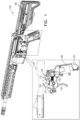
- Fig. 1 is a schematic illustration of a firearm 100 and a trigger assembly 105
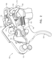
- Fig. 2 is a schematic illustration of a perspective view of a trigger assembly, according to an embodiment of the disclosure.
- the firearm 100 is configured to function in manual mode, for example supporting a safe mode, a semi-automatic mode and an automatic mode.
- the firearm 100 is configured to function in an electromechanical (EM)/computerized mode, wherein an electromechanical firing controller (EMFC) 180 uses a computer to control the release of shots.
- EMFC electromechanical firing controller
- the EMFC 180 may control the release of shots based on analysis of measurements from local or remote sensors, as described in US Patent No. 10,845,148 .
- the firearm functions without requiring an electrical power source 185.
- a power source 185 is required to control the release of bullets or other projectiles.
- the trigger assembly 105 may include the following elements:
- transition between the different modes is performed with safety lever 120.
- the safety lever 120 When changing to EM mode the safety lever 120 is rotated and moves the hammer cocking sear 170 to cock the hammer 110 so that it is held by EM sear 150.
- EMFC 180 releases the stored mechanical energy by releasing the sear lever 162 that pulls downward on an end of EM sear 150 and releases the grasp of EM sear 150 from the hammer 110.
- the hammer 110 then flies forward and releases a shot.
- trigger 130 includes a hooked end 132 that is configured to hold an extrusion 114 from hammer 110. This serves to prevent accidental release of a shot if the trigger 130 is not engaged or releasing a mechanical shot when the safety lever 120 is in semi-auto or automatic position.
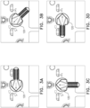
- Fig. 3A-3D are schematic illustrations of safety lever 120 settings, according to an embodiment of the disclosure.
- Fig. 3A shows the position of the safety lever 120, when the firearm 100 is in safe mode
- Fig. 3B shows the position of the safety lever after being rotated, for example by 45 degrees clockwise to a semi-automatic mode position
- Fig. 3C shows the position of the safety lever after being rotated, for example by 90 degrees from the safe position to an automatic fire mode position
- Fig. 3D shows the safety lever after being rotated for example by180 degrees from the safe position to an EM mode position.
- the angle of rotation from the automatic firing mode position to the EM mode position is larger (e.g.
- hammer cocking sear 170 comprises 3 ends.
- One serves as an automatic mode sear 173 to regulate firing in automatic mode.
- One serves as a hammer cocking lever 172 to cock the hammer 110, and one serves as a tail lever 174 to enable the safety lever 120 to push the hammer cocking sear 170.
- hammer cocking sear 170 is formed as a solid unit including hammer cocking lever 172, automatic sear 173 and tail lever 174.
- hammer cocking lever 172, automatic sear 173 and/or tail lever 174 may be separate elements that are coupled together.
- the firearm 100 does not support an automatic mode and the end serving as automatic sear 173 is omitted.
- the safety lever 120 is coupled to an essentially cylindrical element 122 that rotates with the safety lever 120.
- the essentially cylindrical element 122 is formed with crevices and extrusions along an elongated axis of the essentially cylindrical element 122.
- the crevices and extrusions enable or disable movement of the trigger 130, the semi-auto sear/disconnector 140, the EM sear 150 and the automatic mode sear 173 to rise or sink so they are positioned correctly as needed to perform their task, for example to be out of the way or be engaged to act on the hammer 110.
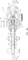
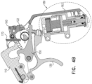
- Figs. 4A-4D are schematic illustrations of a trigger assembly 105 in safe mode, according to an embodiment of the disclosure.
- Fig 4A is a top view showing three cross sectional views;
- Fig. 4B shows a first cross sectional view demonstrating an unengaged EM sear 150;
- Fig. 4C shows a second cross sectional view demonstrating an unengaged semi-auto sear/disconnector 140;
- Fig. 4D shows a third cross sectional view of a released/unpulled/not engaged trigger 130 holding the hammer 110.
- the safety lever 120 and the cylindrical element 122 coupled to safety lever 120 block the trigger 130 and the EM sear 150 from moving, thus preventing manual and computerized firing.
- Fig. 5 is a schematic illustration of a cross sectional view of a semi-auto sear/disconnector 140 in semi-automatic mode, according to an embodiment of the disclosure.
- the safety lever allows motion of the trigger 130, blocks motion of the EM sear 150 and allows motion of the semi-auto sear/disconnector 140. This enables the semi-auto sear/disconnector 140 to hold the hammer 110 after firing a first shot to prevent a second shot until the user releases the trigger 130 and then pulls it again.
- Fig. 6 is a schematic illustration of a cross sectional view of an automatic mode sear 173 in automatic mode, according to an embodiment of the disclosure.
- the safety lever 120 allows motion of the trigger 130, locks motion of the EM sear 150, locks motion of the semi-auto sear/disconnector 140 and allows motion of the automatic mode sear 173to delay release of another bullet until the firearm bolt returns loading another bullet and releasing the automatic mode sear 173 from blocking motion of the hammer 110 to enable the next shot.
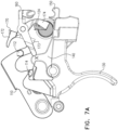
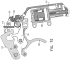
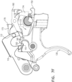
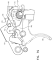
- Figs. 7A-7F are schematic illustrations of a transition from automatic mode to EM mode and vice versa, according to an embodiment of the disclosure.
- a force is required to lower the hammer 110 against the hammer spring 115 ( Fig. 4D ) so that it will be held by the EM sear 150 instead of by the trigger 130.
- the trigger 130 acts as a safety block device and not as the main shooting mechanism.
- Lowering the hammer 110 against the hammer spring 115 is achieved by a system of levers that are added to the safety lever 120 and to the hammer cocking sear 170 to enable cocking the hammer 110 by applying a moderate force by the user on the safety lever 120. Initially the hammer 110 is held by the trigger 130, which prevents release of a shot. As shown in Fig. 7A the following levers are added to allow the transition:
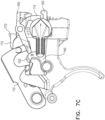
- the hammer cocking sear 170 pushes the hammer 110 downward, so that it will be held by the EM sear 150 instead of by the trigger 130 ( Fig. 7C ).
- Pulling the trigger removes the trigger 130 from serving as a backup block for the hammer 110.
- the hammer 110 is controlled only by the EM sear 150.
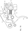
- the safety lever 120 when the safety lever 120 is moved to EM mode, the safety lever causes the EMFC 180 to be activated to control the computerized release of bullets according to a preprogrammed logic. To release a shot the EMFC 180 is activated to release stored energy to pull the EM sear 150 downward with the sear lever 162 thus releasing the hammer 110 ( Fig. 7E ).
- the preprogrammed logic may allow the release of bullets only when firearm sensors identify that a target will be hit.
- the preprogrammed logic may allow release of a first immediate shot and then only release bullets when they are deemed to hit the target or release bullets according to a time pattern, for example every 250 milliseconds or using some other pattern and/or conditions.
- Figures 7F-7H show the reverse transition from EM mode to automatic mode. Initially the user releases the trigger 130 and the trigger 130 is positioned as a secondary safety block for motion of the hammer 110 ( Fig. 7F ). Then the user turns the safety lever 120 counterclockwise, causing the bulge lever 124 or contour 125 of the safety lever 120 to push the tail lever 174 of the hammer cocking sear 170 and rotate the hammer cocking sear 170 counterclockwise ( Fig. 7G ). The rotation pushes the head lever 172 of the hammer cocking sear 170 onto the hammer extrusion lever 112 so the hammer 110 is pressed down ( Fig 7G ).
- the firearm 100 may support other manual modes, for example burst mode.
- the firearm 100 may have fewer manual modes, for example only safe mode and more electromechanical (EM) modes or other combinations.
- EM electromechanical
- safety lever 120 may be configured to rotate clockwise or counterclockwise to transition from EM mode to automatic mode or vice versa. Additionally, the order of the modes may be rearranged.
Landscapes
- Engineering & Computer Science (AREA)
- General Engineering & Computer Science (AREA)
- Toys (AREA)
Claims (15)
- Feuerwaffe (100), enthaltend:einen Schlagbolzen (110);einen Sicherheitshebel (120), der konfiguriert ist, einen Betriebsmodus zu wählen;einen Auslöser (130);einen elektromechanischen Abzug (150);wobei die Betriebsmodi einen elektromechanischen Modus enthalten,dadurch gekennzeichnet, dass die Feuerwaffe (100) so konfiguriert ist, dass der Sicherheitshebel (120) den Schlagbolzen (110) bewegt, dass er durch den elektromechanischen Abzug (150) statt durch den Auslöser(130) gehalten wird, wenn der Sicherheitshebel (120) zum Wählen des elektromechanischen Modus bewegt wird.
- Feuerwaffe (100) nach Anspruch 1, wobei die Feuerwaffe (100) so konfiguriert ist, dass beim Wechseln des Betriebsmodus vom elektromechanischen Modus in einen anderen Modus der Sicherheitshebel (120) den Schlagbolzen (110) so bewegt, dass der Schlagbolzen (110) von dem elektromechanischen Abzug (150) gelöst wird und durch den Auslöser (130) gehalten wird.
- Feuerwaffe (100) nach Anspruch 1, wobei der elektromechanische Modus zusätzlich zu unterstützenden mechanischen Modi ist, die ohne elektrischen Strom funktionieren.
- Feuerwaffe (100) nach Anspruch 1, wobei der Sicherheitshebel (120) konfiguriert ist, dass der Schlagbolzen mit einem Satz von Hebeln (124, 174,172, 112) bewegt wird; wobei der Satz von Hebeln (124, 174, 172, 112) mit dem Sicherheitshebel (120), dem Schlagbolzen (110) und/oder einer Spanvorrichtung (170) für den Schlagbolzen gekoppelt sind.
- Feuerwaffe (100) nach Anspruch 1, wobei die Feuerwaffe (100) eine Spannvorrichtung (170) für den Schlagbolzen enthält; wobei die Spannvorrichtung (170) für den Schlagbolzen einen Kopfhebel (172) und einen Heckhebel (174) enthält; und wobei beim Bewegen des Sicherheitshebels (120) in den elektromechanischen Modus der Sicherheitshebel (120) den Heckhebel (174) der Spannvorrichtung (170) für den Schlagbolzen drückt und bewirkt, dass der Kopfhebel (172) den Schlagbolzen (110) absenkt, dass er durch den elektromechanischen Abzug (150) statt durch den Auslöser (130) gehalten wird.
- Feuerwaffe (100) nach Anspruch 5, wobei die Feuerwaffe (100) einen Automatikmodus-Abzug (173) enthält, der das Feuern in dem Automatikmodus reguliert; und wobei der Automatikmodus-Abzug (173) mit der Spannvorrichtung (170) für den Schlagbolzen gekoppelt ist.
- Feuerwaffe (100) nach Anspruch 5, wobei der Schlagbolzen (110) einen Auszugshebel (112) enthält, der konfiguriert ist, durch den Kopfhebel (172) der Spannvorrichtung (170) für den Schlagbolzen zum Absenken des Schlagbolzens (110) gedrückt zu werden.
- Feuerwaffe (100) nach Anspruch 5, wobei der Sicherheitshebel (120) einen Ausbeulungshebel (124) enthält, der konfiguriert ist, den Heckhebel (174) der Spannvorrichtung (170) für den Schlagbolzen zu drücken, wenn in den oder aus dem elektromechanischen Modus geschaltet wird.
- Feuerwaffe (100) nach Anspruch 1, wobei die Feuerwaffe (100) einen halb-automatischen Abzug (140) enthält, der konfiguriert ist, den Schlagbolzen (110) zu halten unmittelbar nach dem manuellen Freigeben eines ersten Schusses in einem halb-automatischen Modus; und wobei der halb-automatische Abzug (140) parallel zu dem elektromechanischen Abzug (150) positioniert ist.
- Feuerwaffe (100) nach Anspruch 1, wobei der Sicherheitshebel (120) konfiguriert ist, eine Bewegung des elektromechanischen Abzugs (150) zu blockieren, wenn dieser nicht in Verwendung ist.
- Feuerwaffe (100) nach Anspruch 1, wobei die Feuerwaffe (100) eine elektro-mechanische Feuerungskontrolle (EMFC) (180) enthält, die konfiguriert ist, mechanische Energie zu speichern und Schüsse in Abhängigkeit von Computerentscheidungen abzugeben.
- Verfahren zum Betätigen einer Feuerwaffe (100) in einem elektromechanischen Modus, enthaltend:Empfangen einer Feuerwaffe (100) mit einem Schlagbolzen (110), einem Sicherheitshebel (120), einem Auslöser (130) und einem elektromechanischen Abzug (150);Bewegen des Sicherheitshebels (120) zum Auswählen eines elektromechanischen Modus;dadurch gekennzeichnet, dass der Sicherheitshebel (120) den Schlagbolzen (110) bewegt, dass er durch den elektromechanischen Abzug (150) statt durch den Auslöser (130) gehalten wird, wenn der Sicherheitshebel (120) zur Auswahl des elektromechanischen Modus bewegt wird.
- Verfahren nach Anspruch 12, wobei die Feuerwaffe (100) so konfiguriert ist, dass beim Ändern des Betriebsmodus von dem elektromechanischen Modus zu einem anderen Modus der Sicherheitshebel (120) den Schlagbolzen (110) so bewegt, dass der Schlagbolzen (110) von dem elektromechanischen Abzug (150) gelöst wird und durch den Auslöser (130) gehalten wird.
- Verfahren nach Anspruch 12, wobei der Sicherheitshebel (120) den Schlagbolzen (100) mit einem Satz von Hebeln (124, 174, 172, 112) bewegt; wobei der Satz von Hebeln (124, 174, 172, 112) mit dem Sicherheitshebel, dem Schlagbolzen (110) und/oder einer Spannvorrichtung (170) für den Schlagbolzen gekoppelt ist.
- Verfahren nach Anspruch 12, wobei die Feuerwaffe (100) eine Spannvorrichtung (170) für den Schlagbolzen enthält; wobei die Spannvorrichtung (170) für den Schlagbolzen einen Kopfhebel (172) und einen Heckhebel (174) enthält; und wobei beim Bewegen des Sicherheitshebels (120) in den elektromechanischen Modus der Sicherheitshebel (120) den Heckhebel (174) der Spannvorrichtung (170) für den Schlagbolzen drückt und bewirkt, dass der Kopfhebel (172) den Schlagbolzen (110) absenkt, dass er durch den elektromechanischen Abzug (150) statt durch den Auslöser (130) gehalten wird.
Applications Claiming Priority (1)
| Application Number | Priority Date | Filing Date | Title |
|---|---|---|---|
| IL300188A IL300188B2 (en) | 2023-01-25 | 2023-01-25 | Firearm with cocking safety lever |
Publications (3)
| Publication Number | Publication Date |
|---|---|
| EP4407270A1 EP4407270A1 (de) | 2024-07-31 |
| EP4407270C0 EP4407270C0 (de) | 2025-01-22 |
| EP4407270B1 true EP4407270B1 (de) | 2025-01-22 |
Family
ID=89322102
Family Applications (1)
| Application Number | Title | Priority Date | Filing Date |
|---|---|---|---|
| EP23220126.9A Active EP4407270B1 (de) | 2023-01-25 | 2023-12-22 | Feuerwaffe mit spannsicherheitshebel |
Country Status (3)
| Country | Link |
|---|---|
| US (1) | US12326307B2 (de) |
| EP (1) | EP4407270B1 (de) |
| IL (1) | IL300188B2 (de) |
Families Citing this family (1)
| Publication number | Priority date | Publication date | Assignee | Title |
|---|---|---|---|---|
| IL300188B2 (en) * | 2023-01-25 | 2024-10-01 | Israel Weapon Ind I W I Ltd | Firearm with cocking safety lever |
Family Cites Families (15)
| Publication number | Priority date | Publication date | Assignee | Title |
|---|---|---|---|---|
| US4329803A (en) | 1980-07-07 | 1982-05-18 | Browning Arms Company | Electronic set trigger |
| US4727670A (en) | 1986-09-29 | 1988-03-01 | Krouse Edwin E | Electromechanical firing mechanism |
| US5713150A (en) * | 1995-12-13 | 1998-02-03 | Defense Technologies, Llc | Combined mechanical and Electro-mechanical firing mechanism for a firearm |
| US6976416B2 (en) * | 2002-01-23 | 2005-12-20 | Crystal Design, Llc | Solid-state full auto sear |
| US20050257676A1 (en) | 2003-10-23 | 2005-11-24 | Ealovega George D | Weapon with electro-mechanical firing mechanism for use with combination percussive and electrically responsive cartridge primer |
| US8549780B2 (en) | 2008-03-12 | 2013-10-08 | Armatix Gmbh | Safety device for firearms and method for securing firearms provided with a safety device |
| US8336438B2 (en) | 2010-04-26 | 2012-12-25 | Colt Canada Corporation | Electro-mechanical firearm trigger mechanism |
| US9551546B2 (en) * | 2014-08-05 | 2017-01-24 | Benjamin Alicea, JR. | Electronic firearm |
| US20180224231A1 (en) | 2017-02-06 | 2018-08-09 | Brian Weinberg | Firearm and method for using a firearm |
| US10309743B2 (en) | 2017-05-15 | 2019-06-04 | Shyam Swaminadhan Rami | Triggering mechanism for hybrid primer cartridges |
| IL259323B (en) * | 2018-05-13 | 2022-02-01 | Israel Weapon Ind I W I Ltd | An electro-mechanical mechanism for controlling a firing system |
| EP4314693A4 (de) * | 2021-03-24 | 2025-02-26 | Biofire Technologies Inc. | Elektromechanische sicherung und verfahren zum betrieb einer waffe damit |
| WO2022204702A1 (en) * | 2021-03-24 | 2022-09-29 | Biofire Technologies Inc. | User authentication at an electromechanical gun |
| US11555663B2 (en) * | 2021-04-19 | 2023-01-17 | Biofire Technologies Inc. | Electromechanical trigger and methods of operating a gun using the same |
| IL300188B2 (en) * | 2023-01-25 | 2024-10-01 | Israel Weapon Ind I W I Ltd | Firearm with cocking safety lever |
-
2023
- 2023-01-25 IL IL300188A patent/IL300188B2/en unknown
- 2023-12-22 EP EP23220126.9A patent/EP4407270B1/de active Active
-
2024
- 2024-01-16 US US18/413,082 patent/US12326307B2/en active Active
Also Published As
| Publication number | Publication date |
|---|---|
| US12326307B2 (en) | 2025-06-10 |
| IL300188B1 (en) | 2024-06-01 |
| EP4407270C0 (de) | 2025-01-22 |
| IL300188B2 (en) | 2024-10-01 |
| US20240247898A1 (en) | 2024-07-25 |
| EP4407270A1 (de) | 2024-07-31 |
| IL300188A (de) | 2023-02-01 |
Similar Documents
| Publication | Publication Date | Title |
|---|---|---|
| US10731938B2 (en) | Electronic firearm | |
| US10030928B2 (en) | Operating mode selection mechanism and method for a firearm | |
| US8807007B2 (en) | Digital hybrid firearm | |
| US5501134A (en) | Multi-stage match trigger assembly for use with semi-automatic weapons | |
| US5303494A (en) | Handgun having a decocking/safety control device | |
| EP4407270B1 (de) | Feuerwaffe mit spannsicherheitshebel | |
| US20030070342A1 (en) | Decocking lever | |
| WO1997021974A9 (en) | Combined mechanical and electro-mechanical firing mechanism for a firearm | |
| US4545143A (en) | Trigger mechanism for double barrel shotgun | |
| EP3514474B1 (de) | Sicherheitsvorrichtung und sicherheitsverfahren für feuerwaffen | |
| EP3194880B1 (de) | Auslösemechanismus für selbstladende waffe und manuelle selbstladende waffe | |
| US20210247157A1 (en) | Safety mechanism for firearms | |
| US6543169B2 (en) | Semi-automatic firing and disconnecting device for a non-hammer fired machine gun | |
| KR102695138B1 (ko) | 화기를 위한 방아쇠 장치 | |
| US3389488A (en) | Single-trigger release mechanism for a double-barreled shotgun | |
| KR102708899B1 (ko) | 화기를 위한 안전장치 | |
| JP6092852B2 (ja) | 撃針安全装置 | |
| JPS63201500A (ja) | 二連式銃のモノトリガ機構 | |
| NO327314B1 (no) | Anordning ved maskingevaer | |
| US4784036A (en) | Automatic cannon and fire control mechanism | |
| IL271880B1 (en) | Handgun safe dismantling mechanism | |
| US4315377A (en) | Single trigger firing of double barrel side-by-side or over-under firearms | |
| US4444088A (en) | Auto-fire assembly for industrial shotgun | |
| EP4224108B1 (de) | Abzugsmechanismus einer schusswaffe und verfahren zum auslösen einer schusswaffe | |
| EP0125212B1 (de) | Sperrklinkenmechanismus mit Schlussbegrenzer für Feuerwaffen |
Legal Events
| Date | Code | Title | Description |
|---|---|---|---|
| PUAI | Public reference made under article 153(3) epc to a published international application that has entered the european phase |
Free format text: ORIGINAL CODE: 0009012 |
|
| STAA | Information on the status of an ep patent application or granted ep patent |
Free format text: STATUS: REQUEST FOR EXAMINATION WAS MADE |
|
| 17P | Request for examination filed |
Effective date: 20231222 |
|
| AK | Designated contracting states |
Kind code of ref document: A1 Designated state(s): AL AT BE BG CH CY CZ DE DK EE ES FI FR GB GR HR HU IE IS IT LI LT LU LV MC ME MK MT NL NO PL PT RO RS SE SI SK SM TR |
|
| GRAP | Despatch of communication of intention to grant a patent |
Free format text: ORIGINAL CODE: EPIDOSNIGR1 |
|
| STAA | Information on the status of an ep patent application or granted ep patent |
Free format text: STATUS: GRANT OF PATENT IS INTENDED |
|
| INTG | Intention to grant announced |
Effective date: 20241031 |
|
| GRAS | Grant fee paid |
Free format text: ORIGINAL CODE: EPIDOSNIGR3 |
|
| GRAA | (expected) grant |
Free format text: ORIGINAL CODE: 0009210 |
|
| STAA | Information on the status of an ep patent application or granted ep patent |
Free format text: STATUS: THE PATENT HAS BEEN GRANTED |
|
| RAP3 | Party data changed (applicant data changed or rights of an application transferred) |
Owner name: ISRAEL WEAPON INDUSTRIES (I.W.I.) LTD. |
|
| AK | Designated contracting states |
Kind code of ref document: B1 Designated state(s): AL AT BE BG CH CY CZ DE DK EE ES FI FR GB GR HR HU IE IS IT LI LT LU LV MC ME MK MT NL NO PL PT RO RS SE SI SK SM TR |
|
| REG | Reference to a national code |
Ref country code: GB Ref legal event code: FG4D |
|
| REG | Reference to a national code |
Ref country code: CH Ref legal event code: EP |
|
| REG | Reference to a national code |
Ref country code: IE Ref legal event code: FG4D |
|
| REG | Reference to a national code |
Ref country code: DE Ref legal event code: R096 Ref document number: 602023001781 Country of ref document: DE |
|
| U01 | Request for unitary effect filed |
Effective date: 20250218 |
|
| U07 | Unitary effect registered |
Designated state(s): AT BE BG DE DK EE FI FR IT LT LU LV MT NL PT RO SE SI Effective date: 20250224 |
|
| PG25 | Lapsed in a contracting state [announced via postgrant information from national office to epo] |
Ref country code: RS Free format text: LAPSE BECAUSE OF FAILURE TO SUBMIT A TRANSLATION OF THE DESCRIPTION OR TO PAY THE FEE WITHIN THE PRESCRIBED TIME-LIMIT Effective date: 20250422 |
|
| PG25 | Lapsed in a contracting state [announced via postgrant information from national office to epo] |
Ref country code: PL Free format text: LAPSE BECAUSE OF FAILURE TO SUBMIT A TRANSLATION OF THE DESCRIPTION OR TO PAY THE FEE WITHIN THE PRESCRIBED TIME-LIMIT Effective date: 20250122 |
|
| PG25 | Lapsed in a contracting state [announced via postgrant information from national office to epo] |
Ref country code: ES Free format text: LAPSE BECAUSE OF FAILURE TO SUBMIT A TRANSLATION OF THE DESCRIPTION OR TO PAY THE FEE WITHIN THE PRESCRIBED TIME-LIMIT Effective date: 20250122 |
|
| PG25 | Lapsed in a contracting state [announced via postgrant information from national office to epo] |
Ref country code: IS Free format text: LAPSE BECAUSE OF FAILURE TO SUBMIT A TRANSLATION OF THE DESCRIPTION OR TO PAY THE FEE WITHIN THE PRESCRIBED TIME-LIMIT Effective date: 20250522 Ref country code: NO Free format text: LAPSE BECAUSE OF FAILURE TO SUBMIT A TRANSLATION OF THE DESCRIPTION OR TO PAY THE FEE WITHIN THE PRESCRIBED TIME-LIMIT Effective date: 20250422 |
|
| PG25 | Lapsed in a contracting state [announced via postgrant information from national office to epo] |
Ref country code: HR Free format text: LAPSE BECAUSE OF FAILURE TO SUBMIT A TRANSLATION OF THE DESCRIPTION OR TO PAY THE FEE WITHIN THE PRESCRIBED TIME-LIMIT Effective date: 20250122 |
|
| PG25 | Lapsed in a contracting state [announced via postgrant information from national office to epo] |
Ref country code: GR Free format text: LAPSE BECAUSE OF FAILURE TO SUBMIT A TRANSLATION OF THE DESCRIPTION OR TO PAY THE FEE WITHIN THE PRESCRIBED TIME-LIMIT Effective date: 20250423 |
|
| PG25 | Lapsed in a contracting state [announced via postgrant information from national office to epo] |
Ref country code: SM Free format text: LAPSE BECAUSE OF FAILURE TO SUBMIT A TRANSLATION OF THE DESCRIPTION OR TO PAY THE FEE WITHIN THE PRESCRIBED TIME-LIMIT Effective date: 20250122 |
|
| PG25 | Lapsed in a contracting state [announced via postgrant information from national office to epo] |
Ref country code: CZ Free format text: LAPSE BECAUSE OF FAILURE TO SUBMIT A TRANSLATION OF THE DESCRIPTION OR TO PAY THE FEE WITHIN THE PRESCRIBED TIME-LIMIT Effective date: 20250122 |
|
| PG25 | Lapsed in a contracting state [announced via postgrant information from national office to epo] |
Ref country code: SK Free format text: LAPSE BECAUSE OF FAILURE TO SUBMIT A TRANSLATION OF THE DESCRIPTION OR TO PAY THE FEE WITHIN THE PRESCRIBED TIME-LIMIT Effective date: 20250122 |
|
| PLBE | No opposition filed within time limit |
Free format text: ORIGINAL CODE: 0009261 |
|
| STAA | Information on the status of an ep patent application or granted ep patent |
Free format text: STATUS: NO OPPOSITION FILED WITHIN TIME LIMIT |
|
| 26N | No opposition filed |
Effective date: 20251023 |
|
| U20 | Renewal fee for the european patent with unitary effect paid |
Year of fee payment: 3 Effective date: 20251230 |