EP4407260A1 - Schrank für ein kühlgerät - Google Patents
Schrank für ein kühlgerät Download PDFInfo
- Publication number
- EP4407260A1 EP4407260A1 EP24153316.5A EP24153316A EP4407260A1 EP 4407260 A1 EP4407260 A1 EP 4407260A1 EP 24153316 A EP24153316 A EP 24153316A EP 4407260 A1 EP4407260 A1 EP 4407260A1
- Authority
- EP
- European Patent Office
- Prior art keywords
- cabinet
- insulation structure
- wrapper
- glass panel
- liner
- Prior art date
- Legal status (The legal status is an assumption and is not a legal conclusion. Google has not performed a legal analysis and makes no representation as to the accuracy of the status listed.)
- Pending
Links
- 238000005057 refrigeration Methods 0.000 title claims abstract description 46
- 239000011521 glass Substances 0.000 claims abstract description 81
- 239000012774 insulation material Substances 0.000 claims abstract description 25
- 238000009413 insulation Methods 0.000 claims description 27
- 238000000034 method Methods 0.000 claims description 22
- 238000003860 storage Methods 0.000 claims description 15
- 238000004519 manufacturing process Methods 0.000 claims description 9
- 239000000463 material Substances 0.000 claims description 6
- 238000000151 deposition Methods 0.000 claims description 4
- 230000008569 process Effects 0.000 description 9
- 230000008901 benefit Effects 0.000 description 5
- 238000005304 joining Methods 0.000 description 4
- 239000002184 metal Substances 0.000 description 3
- 238000012986 modification Methods 0.000 description 3
- 230000004048 modification Effects 0.000 description 3
- 239000003086 colorant Substances 0.000 description 2
- 238000010276 construction Methods 0.000 description 2
- 230000008878 coupling Effects 0.000 description 2
- 238000010168 coupling process Methods 0.000 description 2
- 238000005859 coupling reaction Methods 0.000 description 2
- 238000002347 injection Methods 0.000 description 2
- 239000007924 injection Substances 0.000 description 2
- 239000000843 powder Substances 0.000 description 2
- 239000003507 refrigerant Substances 0.000 description 2
- 239000000853 adhesive Substances 0.000 description 1
- 230000001070 adhesive effect Effects 0.000 description 1
- 230000000712 assembly Effects 0.000 description 1
- 238000000429 assembly Methods 0.000 description 1
- 238000004891 communication Methods 0.000 description 1
- 238000013461 design Methods 0.000 description 1
- 238000010586 diagram Methods 0.000 description 1
- 239000012530 fluid Substances 0.000 description 1
- 239000006260 foam Substances 0.000 description 1
- 230000009467 reduction Effects 0.000 description 1
- 238000012552 review Methods 0.000 description 1
- 238000006467 substitution reaction Methods 0.000 description 1
Images



Classifications
-
- F—MECHANICAL ENGINEERING; LIGHTING; HEATING; WEAPONS; BLASTING
- F25—REFRIGERATION OR COOLING; COMBINED HEATING AND REFRIGERATION SYSTEMS; HEAT PUMP SYSTEMS; MANUFACTURE OR STORAGE OF ICE; LIQUEFACTION SOLIDIFICATION OF GASES
- F25D—REFRIGERATORS; COLD ROOMS; ICE-BOXES; COOLING OR FREEZING APPARATUS NOT OTHERWISE PROVIDED FOR
- F25D23/00—General constructional features
- F25D23/02—Doors; Covers
-
- F—MECHANICAL ENGINEERING; LIGHTING; HEATING; WEAPONS; BLASTING
- F25—REFRIGERATION OR COOLING; COMBINED HEATING AND REFRIGERATION SYSTEMS; HEAT PUMP SYSTEMS; MANUFACTURE OR STORAGE OF ICE; LIQUEFACTION SOLIDIFICATION OF GASES
- F25D—REFRIGERATORS; COLD ROOMS; ICE-BOXES; COOLING OR FREEZING APPARATUS NOT OTHERWISE PROVIDED FOR
- F25D23/00—General constructional features
- F25D23/06—Walls
- F25D23/062—Walls defining a cabinet
- F25D23/063—Walls defining a cabinet formed by an assembly of panels
-
- F—MECHANICAL ENGINEERING; LIGHTING; HEATING; WEAPONS; BLASTING
- F25—REFRIGERATION OR COOLING; COMBINED HEATING AND REFRIGERATION SYSTEMS; HEAT PUMP SYSTEMS; MANUFACTURE OR STORAGE OF ICE; LIQUEFACTION SOLIDIFICATION OF GASES
- F25D—REFRIGERATORS; COLD ROOMS; ICE-BOXES; COOLING OR FREEZING APPARATUS NOT OTHERWISE PROVIDED FOR
- F25D23/00—General constructional features
- F25D23/06—Walls
-
- F—MECHANICAL ENGINEERING; LIGHTING; HEATING; WEAPONS; BLASTING
- F25—REFRIGERATION OR COOLING; COMBINED HEATING AND REFRIGERATION SYSTEMS; HEAT PUMP SYSTEMS; MANUFACTURE OR STORAGE OF ICE; LIQUEFACTION SOLIDIFICATION OF GASES
- F25D—REFRIGERATORS; COLD ROOMS; ICE-BOXES; COOLING OR FREEZING APPARATUS NOT OTHERWISE PROVIDED FOR
- F25D23/00—General constructional features
- F25D23/06—Walls
- F25D23/062—Walls defining a cabinet
-
- F—MECHANICAL ENGINEERING; LIGHTING; HEATING; WEAPONS; BLASTING
- F25—REFRIGERATION OR COOLING; COMBINED HEATING AND REFRIGERATION SYSTEMS; HEAT PUMP SYSTEMS; MANUFACTURE OR STORAGE OF ICE; LIQUEFACTION SOLIDIFICATION OF GASES
- F25D—REFRIGERATORS; COLD ROOMS; ICE-BOXES; COOLING OR FREEZING APPARATUS NOT OTHERWISE PROVIDED FOR
- F25D23/00—General constructional features
- F25D23/06—Walls
- F25D23/062—Walls defining a cabinet
- F25D23/064—Walls defining a cabinet formed by moulding, e.g. moulding in situ
-
- F—MECHANICAL ENGINEERING; LIGHTING; HEATING; WEAPONS; BLASTING
- F25—REFRIGERATION OR COOLING; COMBINED HEATING AND REFRIGERATION SYSTEMS; HEAT PUMP SYSTEMS; MANUFACTURE OR STORAGE OF ICE; LIQUEFACTION SOLIDIFICATION OF GASES
- F25D—REFRIGERATORS; COLD ROOMS; ICE-BOXES; COOLING OR FREEZING APPARATUS NOT OTHERWISE PROVIDED FOR
- F25D23/00—General constructional features
- F25D23/06—Walls
- F25D23/065—Details
- F25D23/066—Liners
-
- F—MECHANICAL ENGINEERING; LIGHTING; HEATING; WEAPONS; BLASTING
- F25—REFRIGERATION OR COOLING; COMBINED HEATING AND REFRIGERATION SYSTEMS; HEAT PUMP SYSTEMS; MANUFACTURE OR STORAGE OF ICE; LIQUEFACTION SOLIDIFICATION OF GASES
- F25D—REFRIGERATORS; COLD ROOMS; ICE-BOXES; COOLING OR FREEZING APPARATUS NOT OTHERWISE PROVIDED FOR
- F25D2201/00—Insulation
- F25D2201/10—Insulation with respect to heat
- F25D2201/14—Insulation with respect to heat using subatmospheric pressure
Definitions
- the present disclosure generally relates to a cabinet for a refrigeration unit. More specifically, the present disclosure relates to a vacuum insulated cabinet for a refrigeration unit that includes a glass panel.
- a refrigeration unit includes a cabinet that includes a wrapper that includes a first glass panel, a liner that includes a second glass panel, and insulation material disposed between the liner and the wrapper.
- the refrigeration unit also includes a compressor positioned within a machine compartment at least partially defined by the cabinet.
- the terms “upper,” “lower,” “right,” “left,” “rear,” “front,” “vertical,” “horizontal,” and derivatives thereof shall relate to the disclosure as oriented in FIG. 2 .
- the term “front” shall refer to the surface of the element closer to an intended viewer, and the term “rear” shall refer to the surface of the element further from the intended viewer.
- the disclosure may assume various alternative orientations, except where expressly specified to the contrary.
- the specific devices and processes illustrated in the attached drawings, and described in the following specification are simply exemplary embodiments of the inventive concepts defined in the appended claims. Hence, specific dimensions and other physical characteristics relating to the embodiments disclosed herein are not to be considered as limiting, unless the claims expressly state otherwise.
- a refrigeration unit 10 includes a cabinet 12.
- the cabinet 12 includes a wrapper 14.
- the wrapper 14 includes a first glass panel 16.
- the cabinet 12 further includes a liner 18 that includes a second glass panel 20.
- Insulation material 22 is disposed between the liner 18 and the wrapper 14 of the cabinet 12.
- the cabinet 12 at least partially defines a machine compartment 21 of the refrigeration unit 10.
- a compressor 23 is positioned within the machine compartment 21.
- the compressor 23 is a component of a refrigerant circuit that cools the refrigeration unit 10.
- the refrigerant circuit can include a variety of other components (e.g., evaporator, capillary tube, condenser, etc.).
- the cabinet 12 of the refrigeration unit 10 can be an insulated cabinet 12.
- the cabinet 12 can be a vacuum insulated cabinet 12, as described further herein.
- the cabinet 12 can include the wrapper 14 and the liner 18.
- the liner 18 can be positioned inboard of the wrapper 14.
- the liner 18 defines a storage compartment 24 of the refrigeration unit 10 and the wrapper 14 is positioned outboard of the liner 18.
- the refrigeration unit 10 can include a plurality of storage compartments 24, such as a freezer compartment and a refrigerator compartment, in various embodiments.
- the cabinet 12 defines an interior volume 26. As illustrated in FIG.
- the liner 18 and the wrapper 14 of the cabinet 12 define the interior volume 26 which is disposed between the liner 18 and the wrapper 14 of the cabinet 12.
- Insulation material 22 e.g., powder, foam, panels, etc.
- the insulation material 22 is disposed between the liner 18 and the wrapper 14 within the interior volume 26 of the cabinet 12.
- the cabinet 12 of the refrigeration unit 10 can include a trim breaker 28.
- the trim breaker 28 can be positioned at a front perimeter 30 of the cabinet 12 that extends about an opening 32 to the storage compartment 24 defined by the liner 18 of the cabinet 12.
- the trim breaker 28 can partially define the interior volume 26 of the cabinet 12.
- the trim breaker 28 can define the interior volume 26 of the cabinet 12 together with the liner 18 and the wrapper 14 of the cabinet 12. As illustrated in FIG.
- the wrapper 14 terminates at a terminal end 34 of the wrapper 14 proximate to the front perimeter 30 of the cabinet 12, and the liner 18 terminates at a terminal end 36 of the liner 18 proximate to the front perimeter 30 of the cabinet 12.
- the trim breaker 28 is coupled to the terminal end 34 of the wrapper 14 and the terminal end 36 of the liner 18 and spans the gap between the respective terminal ends 34, 36 of the wrapper 14 and liner 18 to enclose the interior volume 26 defined by the cabinet 12.
- the trim breaker 28 can be coupled to the wrapper 14 and liner 18 in a variety of manners, such as via an adhesive.
- the cabinet 12 includes a glass panel 38.
- the cabinet 12 includes a plurality of glass panels 38.
- the cabinet 12 can include the first glass panel 16 and the second glass panel 20.
- the glass panel 38 can have a thickness of less than 1 millimeter (mm).
- the glass panel can have a thickness between about 0.4 millimeters and 1 millimeter.
- the wrapper 14 includes the glass panel 38.
- the liner 18 includes the glass panel 38.
- the wrapper 14 includes the first glass panel 16 and the liner 18 includes the second glass panel 20.
- the glass panel 38 of the cabinet 12 can be substantially impermeable with respect to air, such that the interior volume 26 of the cabinet 12 may be evacuated to form a vacuum insulated cabinet 12.
- the glass panel 38 of the cabinet 12 can be a plastic overmolded glass panel 38.
- the glass panel 38 can be overmolded with plastic. It is contemplated that the glass panel 38 can be overmolded with plastic in a variety of manners (e.g., cast overmolding, injection overmolding, etc.).
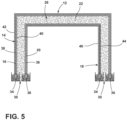
- the wrapper 14 includes the first plastic overmolded glass panel 16, and the liner 18 includes the second plastic overmolded glass panel 20. As illustrated in FIG. 5 , the wrapper 14 includes a plastic inner wrapper layer 40 that is positioned between the insulation material 22 disposed within the interior volume 26 of the cabinet 12 and the first glass panel 16 of the wrapper 14.
- the wrapper 14 further includes a plastic outer wrapper layer 42 that is positioned outboard of the first glass panel 16 such that the first glass panel 16 is positioned between the plastic inner and outer wrapper layers 40, 42.
- the liner 18 illustrated in FIG. 5 includes a plastic outer liner layer 44.
- the plastic outer liner layer 44 is positioned between insulation material 22 disposed within the interior volume 26 defined by the cabinet 12 and the second glass panel 20.
- the liner 18 further includes a plastic inner liner layer 46 that is positioned inboard of the second glass panel 20 such that the second glass panel 20 is positioned between the plastic inner and outer liner layers 46, 44.
- the plastic inner liner layer 46 defines the storage compartment 24 of the refrigeration unit 10.
- the plastic inner liner layer 46 is coupled to the plastic outer wrapper layer 42.
- the plastic inner liner layer 46 and the plastic outer wrapper layer 42 are integrally molded.
- the plastic inner liner layer 46 and the plastic outer wrapper layer 42 converge proximate to the front perimeter 30 of the cabinet 12.
- the plastic outer liner layer 44 can be coupled to the plastic inner wrapper layer 40.
- the plastic outer liner layer 44 and the plastic inner wrapper layer 40 are integrally molded. In the embodiment illustrated in FIG.
- the cabinet 12 may define the interior volume 26 without the trim breaker 28, as illustrated in FIG. 3 .
- a method 100 of manufacturing an insulated cabinet 12 for a refrigeration unit 10 includes a step 110 of overmolding a glass panel 38 of the cabinet 12 with plastic.
- the glass panel 38 of the cabinet 12 can form a portion of the wrapper 14 of the cabinet 12 and/or a portion of the liner 18 of the cabinet 12. It is contemplated that the step 110 of overmolding the glass panel 38 of the cabinet 12 with plastic may be executed in a variety of manners, such as injection overmolding or cast overmolding.
- step 110 of overmolding the glass panel 38 of the cabinet 12 with plastic may include overmolding the first glass panel 16 to form at least a portion of the wrapper 14 and/or overmolding the second glass panel 20 to form at least a portion of the liner 18.
- the method 100 of manufacturing the insulated cabinet 12 for the refrigeration unit 10 may include a step 120 of installing the trim breaker 28 of the cabinet 12.
- the trim breaker 28 may be installed at the front perimeter 30 of the cabinet 12.
- the step 120 can entail coupling the trim breaker 28 to the terminal ends 34, 36 of the wrapper 14 and liner 18, respectively, as illustrated in FIG. 5 , wherein the trim breaker 28 spans the gap between the terminal ends 34, 36 of the wrapper 14 and the liner 18.
- the interior volume 26 defined by the cabinet 12 is partially defined by the trim breaker 28 of the cabinet 12.
- the method 100 of manufacturing the insulated cabinet 12 for the refrigeration unit 10 can further include a step 130 of depositing insulation material 22 within the interior volume 26 defined by the cabinet 12.
- the insulation material 22 can be deposited within the interior volume 26 defined by the cabinet 12 in a variety of manners.
- the insulation material 22 may be an insulated powder that is delivered into the interior volume 26 through an aperture defined by the cabinet 12.
- the insulation material 22 may include insulation panels that are fitted with a portion of the cabinet 12, such as the liner 18 or wrapper 14, prior to assembly of the liner 18 and wrapper 14 of the cabinet 12.
- the method 100 of manufacturing the insulated cabinet 12 for the refrigeration unit 10 may include a step 140 of evacuating air from the interior volume 26 defined by the cabinet 12 to form a vacuum sealed environment.
- the insulation material 22 deposited within the interior volume 26 remains within the interior volume 26 as the interior volume 26 is evacuated of air. Evacuation may occur, in an exemplary embodiment, by utilizing a vacuum operably coupled with a conduit (not shown) that extends outside of the interior volume 26 yet is in fluid communication with the interior volume 26.
- the conduit may be crimped upon completion of the evacuation process to seal the interior volume 26 of the cabinet 12.
- the cabinet 12 of the present disclosure may provide a variety of advantages.
- the glass panel 38 of the cabinet 12 being impermeable with respect to air can allow for an interior environment of the cabinet 12 to be evacuated and sealed in a generally airtight manner.
- the cabinet 12 being formed of one or more relatively thin and lightweight glass panels 38 that are overmolded with plastic rather than a metal panel may reduce the weight of the cabinet 12, which may allow for convenient handling of the refrigeration unit 10 by a user.
- the cabinet 12 including the glass panel 38 that extends along the front perimeter 30 of the cabinet 12 and not including metal may allow for the trim breaker 28 to be omitted from the cabinet 12, which may reduce the complexity of assembling and the number of parts required to manufacture the cabinet 12.
- the invention as defined in the appended claims can be also applied to each of the doors of the refrigeration unit 10 (coupled to the cabinet 12 generally by means of one or more hinges).
- the invention as defined in the appended claims may be also applied to the door associated to the refrigeration compartment (shown in figure 1 in the respective open position) and/or to the door associated to the freezer compartment (shown in figure 1 in the respective closed position).
- a refrigeration unit includes a cabinet and a compressor positioned within a machine compartment at least partially defined by the cabinet.
- the cabinet includes a wrapper that includes a first glass panel, a liner that includes a second glass panel, and insulation material disposed between the liner and the wrapper.
- the wrapper further includes a plastic inner wrapper layer positioned between the insulation material and the first glass panel, and a plastic outer wrapper layer positioned outboard of the first glass panel such that the first glass panel is positioned between the plastic inner and outer wrapper layers.
- the liner further includes a plastic outer liner layer positioned between the insulation material and the second glass panel, and a plastic inner liner layer positioned inboard of the second glass panel such that the second glass panel is positioned between the plastic inner and outer liner layers.
- the plastic inner liner layer defines a storage compartment.
- the plastic inner liner layer is coupled to the plastic outer wrapper layer.
- the plastic inner liner layer and the plastic outer wrapper layer are integrally molded.
- the plastic outer liner layer is coupled to the plastic inner wrapper layer.
- the plastic outer liner layer and the plastic inner wrapper layer are integrally molded.
- a trim breaker is coupled to a terminal end of the wrapper and a terminal end of the liner.
- the trim breaker is positioned at a front perimeter of the cabinet that extends about an opening to a storage compartment of the cabinet.
- the first glass panel is overmolded with plastic.
- the second glass panel is overmolded with plastic.
- the cabinet is a vacuum insulated cabinet.
- a vacuum insulated cabinet of a refrigeration unit includes a liner that defines a storage compartment of the refrigeration unit, a wrapper, and insulation material disposed within an interior volume defined by the liner and the wrapper, wherein at least one of the liner and the wrapper includes a plastic overmolded glass panel.
- a trim breaker is coupled to a terminal end of the liner and a terminal end of the wrapper at a front perimeter of the cabinet that surrounds an opening to the storage compartment.
- the liner includes the plastic overmolded glass panel.
- a method of manufacturing an insulated cabinet for a refrigeration unit comprises the steps of overmolding a glass panel of the cabinet with plastic, depositing insulation material within an interior volume defined by the cabinet, and evacuating air from the interior volume defined by the cabinet to form a vacuum sealed environment.
- the glass panel forms a portion of a wrapper of the cabinet.
- the glass panel forms a portion of a liner of the cabinet.
- the method further includes the step of installing a trim breaker of the cabinet.
- the interior volume defined by the cabinet is partially defined by the trim breaker.
- a refrigeration unit includes a cabinet that comprises a wrapper that includes a first glass panel, a liner that includes a second glass panel, and insulation material disposed between the liner and the wrapper.
- the refrigeration unit also includes a compressor positioned within a machine compartment at least partially defined by the cabinet.
- the wrapper further includes a plastic inner wrapper layer positioned between the insulation material and the first glass panel, and a plastic outer wrapper layer positioned outboard of the first glass panel such that the first glass panel is positioned between the plastic inner and outer wrapper layers.
- the liner further includes a plastic outer liner layer positioned between the insulation material and the second glass panel, and a plastic inner liner layer positioned inboard of the second glass panel such that the second glass panel is positioned between the plastic inner and outer liner layers.
- the plastic inner liner layer defines a storage compartment.
- the plastic inner liner layer is coupled to the plastic outer wrapper layer.
- the plastic inner liner layer and the plastic outer wrapper layer are integrally molded.
- the plastic outer liner layer is coupled to the plastic inner wrapper layer.
- the plastic outer liner layer and the plastic inner wrapper layer are integrally molded.
- a trim breaker is coupled to a terminal end of the wrapper and a terminal end of the liner.
- the trim breaker is positioned at a front perimeter of the cabinet that extends about an opening to a storage compartment of the cabinet.
- the first glass panel is overmolded with plastic.
- the second glass panel is overmolded with plastic.
- the cabinet is a vacuum insulated cabinet.
- a method of manufacturing an insulated cabinet for a refrigeration unit includes the steps of overmolding a glass panel of the cabinet with plastic, depositing insulation material within an interior volume defined by the cabinet, and evacuating air from the interior volume defined by the cabinet to form a vacuum sealed environment.
- the method further includes the step of installing a trim breaker of the cabinet.
- the interior volume defined by the cabinet is partially defined by the trim breaker.
- the term "coupled” in all of its forms, couple, coupling, coupled, etc. generally means the joining of two components (electrical or mechanical) directly or indirectly to one another. Such joining may be stationary in nature or movable in nature. Such joining may be achieved with the two components (electrical or mechanical) and any additional intermediate members being integrally formed as a single unitary body with one another or with the two components. Such joining may be permanent in nature or may be removable or releasable in nature unless otherwise stated.
- elements shown as integrally formed may be constructed of multiple parts or elements shown as multiple parts may be integrally formed, the operation of the interfaces may be reversed or otherwise varied, the length or width of the structures and/or members or connectors or other elements of the system may be varied, the nature or number of adjustment positions provided between the elements may be varied.
- the elements and/or assemblies of the system may be constructed from any of a wide variety of materials that provide sufficient strength or durability, in any of a wide variety of colors, textures, and combinations. Accordingly, all such modifications are intended to be included within the scope of the present innovations. Other substitutions, modifications, changes, and omissions may be made in the design, operating conditions, and arrangement of the desired and other exemplary embodiments without departing from the spirit of the present innovations.
Landscapes
- Engineering & Computer Science (AREA)
- Chemical & Material Sciences (AREA)
- Combustion & Propulsion (AREA)
- Physics & Mathematics (AREA)
- Mechanical Engineering (AREA)
- Thermal Sciences (AREA)
- General Engineering & Computer Science (AREA)
- Refrigerator Housings (AREA)
Applications Claiming Priority (1)
| Application Number | Priority Date | Filing Date | Title |
|---|---|---|---|
| US18/158,829 US20240247864A1 (en) | 2023-01-24 | 2023-01-24 | Cabinet for a refrigeration unit |
Publications (1)
| Publication Number | Publication Date |
|---|---|
| EP4407260A1 true EP4407260A1 (de) | 2024-07-31 |
Family
ID=89707629
Family Applications (1)
| Application Number | Title | Priority Date | Filing Date |
|---|---|---|---|
| EP24153316.5A Pending EP4407260A1 (de) | 2023-01-24 | 2024-01-23 | Schrank für ein kühlgerät |
Country Status (3)
| Country | Link |
|---|---|
| US (1) | US20240247864A1 (de) |
| EP (1) | EP4407260A1 (de) |
| CN (1) | CN118391861A (de) |
Citations (5)
| Publication number | Priority date | Publication date | Assignee | Title |
|---|---|---|---|---|
| US2617551A (en) * | 1947-01-08 | 1952-11-11 | William Krielaus | Refrigerator and its construction |
| WO2010127947A2 (de) * | 2009-05-04 | 2010-11-11 | BSH Bosch und Siemens Hausgeräte GmbH | Haushaltskältegerät und wärmeisolierende wandung eines haushaltskältegerätes |
| CN102126315A (zh) * | 2010-12-28 | 2011-07-20 | 苏州禾盛新型材料股份有限公司 | 喷绘印刷的复合板材 |
| CN203421886U (zh) * | 2013-08-30 | 2014-02-05 | 合肥美菱股份有限公司 | 一种冰箱用玻璃门体 |
| CN207487227U (zh) * | 2015-12-09 | 2018-06-12 | 三菱电机株式会社 | 制冷冰箱 |
Family Cites Families (16)
| Publication number | Priority date | Publication date | Assignee | Title |
|---|---|---|---|---|
| US5424130A (en) * | 1991-05-13 | 1995-06-13 | Toyota Jidosha Kabushiki Kaisha | Water repellent glass and process for producing the same |
| JPH05126461A (ja) * | 1991-11-07 | 1993-05-21 | Matsushita Refrig Co Ltd | 断熱扉 |
| US7665810B2 (en) * | 2007-04-10 | 2010-02-23 | Maytag Corporation | Kitchen appliance having a floating glass panel |
| EP2627957B1 (de) * | 2010-10-11 | 2019-11-06 | LG Electronics Inc. | Vakuumisolations-glasscheibe und kühlschrank damit |
| US8986483B2 (en) * | 2012-04-02 | 2015-03-24 | Whirlpool Corporation | Method of making a folded vacuum insulated structure |
| KR101383959B1 (ko) * | 2012-06-25 | 2014-04-10 | 엘지전자 주식회사 | 미러 효과를 갖는 외장 필름 |
| US10690391B2 (en) * | 2013-03-15 | 2020-06-23 | Whirlpool Corporation | Appliance using heated glass panels |
| US10610985B2 (en) * | 2015-12-28 | 2020-04-07 | Whirlpool Corporation | Multilayer barrier materials with PVD or plasma coating for vacuum insulated structure |
| WO2018044274A1 (en) * | 2016-08-30 | 2018-03-08 | Whirlpool Corporation | Hermetically sealed overmolded plastic thermal bridge breaker with liner and wrapper for a vacuum insulated structure |
| EP3519746B1 (de) * | 2016-10-03 | 2022-10-26 | Whirlpool Corporation | Verkapselungssystem für eine wärmebrückenschutzschalter-zu-metall-auskleidung |
| WO2018199980A1 (en) * | 2017-04-28 | 2018-11-01 | Whirlpool Corporation | Structural insulating component for a multi-layer insulation system of a vacuum insulated structure |
| EP4502515A3 (de) * | 2017-12-18 | 2025-07-16 | Whirlpool Corporation | Kühlschrank mit einer wandplatte mit einer beleuchtungsstruktur |
| US10837697B2 (en) * | 2018-10-31 | 2020-11-17 | Whirlpool Corporation | Polymer trim breaker having gas-blocking flakes and an epoxy coating |
| US11320194B2 (en) * | 2019-04-30 | 2022-05-03 | Whirlpool Corporation | Barrier layer for insulated structures |
| US11287177B2 (en) * | 2019-10-11 | 2022-03-29 | Whirlpool Corporation | Vacuum insulated structure |
| EP4226104A1 (de) * | 2020-10-07 | 2023-08-16 | Electrolux Appliances Aktiebolag | Kühlschrank |
-
2023
- 2023-01-24 US US18/158,829 patent/US20240247864A1/en active Pending
-
2024
- 2024-01-23 EP EP24153316.5A patent/EP4407260A1/de active Pending
- 2024-01-23 CN CN202410094249.7A patent/CN118391861A/zh active Pending
Patent Citations (5)
| Publication number | Priority date | Publication date | Assignee | Title |
|---|---|---|---|---|
| US2617551A (en) * | 1947-01-08 | 1952-11-11 | William Krielaus | Refrigerator and its construction |
| WO2010127947A2 (de) * | 2009-05-04 | 2010-11-11 | BSH Bosch und Siemens Hausgeräte GmbH | Haushaltskältegerät und wärmeisolierende wandung eines haushaltskältegerätes |
| CN102126315A (zh) * | 2010-12-28 | 2011-07-20 | 苏州禾盛新型材料股份有限公司 | 喷绘印刷的复合板材 |
| CN203421886U (zh) * | 2013-08-30 | 2014-02-05 | 合肥美菱股份有限公司 | 一种冰箱用玻璃门体 |
| CN207487227U (zh) * | 2015-12-09 | 2018-06-12 | 三菱电机株式会社 | 制冷冰箱 |
Also Published As
| Publication number | Publication date |
|---|---|
| CN118391861A (zh) | 2024-07-26 |
| US20240247864A1 (en) | 2024-07-25 |
Similar Documents
| Publication | Publication Date | Title |
|---|---|---|
| EP3647697B1 (de) | Schrankanordnung eines geräts | |
| US12078411B2 (en) | Cabinet reinforcing assembly | |
| US11353256B2 (en) | Hinge support assembly | |
| EP3683487B1 (de) | Vakuumisolierte struktur mit filtermerkmalen in einem vakuumhohlraum | |
| US11732954B2 (en) | Refrigeration appliance cabinet assembly | |
| US12235038B2 (en) | Trim breaker for a structural cabinet that incorporates a structural glass contact surface | |
| EP3548813B1 (de) | Scharnierhalteanordnung | |
| US20220128294A1 (en) | Filling ports for insulated structures incorporated within an appliance | |
| EP4166740A1 (de) | Scharnieranordnung für eine vakuumisolierte tür | |
| EP3491309B1 (de) | Verfahren zur sicherstellung zuverlässiger kernmaterialbefüllung um die durchgänge herum in einer vakuumisolierten struktur | |
| EP3507554A1 (de) | Hermetisch abgedichteter, überspritzter kunststoffwärmebrückentrennschalter mit auskleidung und hülle für eine vakuumisolierte struktur | |
| US12031769B2 (en) | Attachment assembly for an insulated door | |
| US11859895B2 (en) | Refrigeration unit | |
| US20250044016A1 (en) | Support system for a vacuum insulated panel | |
| US20210108851A1 (en) | Vacuum insulated door structure for an appliance incorporating a dispenser structure | |
| US20240247864A1 (en) | Cabinet for a refrigeration unit | |
| US20260078944A1 (en) | Insulated structure for a refrigeration unit | |
| US12535260B2 (en) | Trimbreaker ladder cover | |
| US20250027705A1 (en) | Refrigeration appliance with a door projection to reduce thermal transfer at door and cabinet interface |
Legal Events
| Date | Code | Title | Description |
|---|---|---|---|
| PUAI | Public reference made under article 153(3) epc to a published international application that has entered the european phase |
Free format text: ORIGINAL CODE: 0009012 |
|
| STAA | Information on the status of an ep patent application or granted ep patent |
Free format text: STATUS: THE APPLICATION HAS BEEN PUBLISHED |
|
| AK | Designated contracting states |
Kind code of ref document: A1 Designated state(s): AL AT BE BG CH CY CZ DE DK EE ES FI FR GB GR HR HU IE IS IT LI LT LU LV MC ME MK MT NL NO PL PT RO RS SE SI SK SM TR |
|
| P01 | Opt-out of the competence of the unified patent court (upc) registered |
Free format text: CASE NUMBER: APP_49085/2024 Effective date: 20240828 |
|
| STAA | Information on the status of an ep patent application or granted ep patent |
Free format text: STATUS: REQUEST FOR EXAMINATION WAS MADE |
|
| 17P | Request for examination filed |
Effective date: 20250130 |