EP4407259A1 - Transport refrigerator unit - Google Patents
Transport refrigerator unit Download PDFInfo
- Publication number
- EP4407259A1 EP4407259A1 EP21962438.4A EP21962438A EP4407259A1 EP 4407259 A1 EP4407259 A1 EP 4407259A1 EP 21962438 A EP21962438 A EP 21962438A EP 4407259 A1 EP4407259 A1 EP 4407259A1
- Authority
- EP
- European Patent Office
- Prior art keywords
- opening
- casing
- plate
- refrigeration unit
- heat exchanger
- Prior art date
- Legal status (The legal status is an assumption and is not a legal conclusion. Google has not performed a legal analysis and makes no representation as to the accuracy of the status listed.)
- Pending
Links
Images



Classifications
-
- F—MECHANICAL ENGINEERING; LIGHTING; HEATING; WEAPONS; BLASTING
- F25—REFRIGERATION OR COOLING; COMBINED HEATING AND REFRIGERATION SYSTEMS; HEAT PUMP SYSTEMS; MANUFACTURE OR STORAGE OF ICE; LIQUEFACTION SOLIDIFICATION OF GASES
- F25D—REFRIGERATORS; COLD ROOMS; ICE-BOXES; COOLING OR FREEZING APPARATUS NOT OTHERWISE PROVIDED FOR
- F25D11/00—Self-contained movable devices, e.g. domestic refrigerators
-
- B—PERFORMING OPERATIONS; TRANSPORTING
- B60—VEHICLES IN GENERAL
- B60H—ARRANGEMENTS OF HEATING, COOLING, VENTILATING OR OTHER AIR-TREATING DEVICES SPECIALLY ADAPTED FOR PASSENGER OR GOODS SPACES OF VEHICLES
- B60H1/00—Heating, cooling or ventilating devices
- B60H1/00007—Combined heating, ventilating, or cooling devices
- B60H1/00014—Combined heating, ventilating, or cooling devices for load cargos on load transporting vehicles
-
- B—PERFORMING OPERATIONS; TRANSPORTING
- B60—VEHICLES IN GENERAL
- B60H—ARRANGEMENTS OF HEATING, COOLING, VENTILATING OR OTHER AIR-TREATING DEVICES SPECIALLY ADAPTED FOR PASSENGER OR GOODS SPACES OF VEHICLES
- B60H1/00—Heating, cooling or ventilating devices
- B60H1/32—Cooling devices
- B60H1/3204—Cooling devices using compression
- B60H1/3232—Cooling devices using compression particularly adapted for load transporting vehicles
-
- F—MECHANICAL ENGINEERING; LIGHTING; HEATING; WEAPONS; BLASTING
- F25—REFRIGERATION OR COOLING; COMBINED HEATING AND REFRIGERATION SYSTEMS; HEAT PUMP SYSTEMS; MANUFACTURE OR STORAGE OF ICE; LIQUEFACTION SOLIDIFICATION OF GASES
- F25D—REFRIGERATORS; COLD ROOMS; ICE-BOXES; COOLING OR FREEZING APPARATUS NOT OTHERWISE PROVIDED FOR
- F25D11/00—Self-contained movable devices, e.g. domestic refrigerators
- F25D11/003—Transport containers
-
- F—MECHANICAL ENGINEERING; LIGHTING; HEATING; WEAPONS; BLASTING
- F25—REFRIGERATION OR COOLING; COMBINED HEATING AND REFRIGERATION SYSTEMS; HEAT PUMP SYSTEMS; MANUFACTURE OR STORAGE OF ICE; LIQUEFACTION SOLIDIFICATION OF GASES
- F25D—REFRIGERATORS; COLD ROOMS; ICE-BOXES; COOLING OR FREEZING APPARATUS NOT OTHERWISE PROVIDED FOR
- F25D19/00—Arrangement or mounting of refrigeration units with respect to devices or objects to be refrigerated, e.g. infrared detectors
-
- F—MECHANICAL ENGINEERING; LIGHTING; HEATING; WEAPONS; BLASTING
- F25—REFRIGERATION OR COOLING; COMBINED HEATING AND REFRIGERATION SYSTEMS; HEAT PUMP SYSTEMS; MANUFACTURE OR STORAGE OF ICE; LIQUEFACTION SOLIDIFICATION OF GASES
- F25D—REFRIGERATORS; COLD ROOMS; ICE-BOXES; COOLING OR FREEZING APPARATUS NOT OTHERWISE PROVIDED FOR
- F25D19/00—Arrangement or mounting of refrigeration units with respect to devices or objects to be refrigerated, e.g. infrared detectors
- F25D19/003—Arrangement or mounting of refrigeration units with respect to devices or objects to be refrigerated, e.g. infrared detectors with respect to movable containers
Definitions
- the present disclosure relates to a transport refrigeration unit.
- PTL 1 discloses a condenser unit for a transport refrigeration device that can be attached to a front wall or a roof of a vehicle.
- the present disclosure has been made to solve the above problems, and an object thereof is to provide a transport refrigeration unit capable of improving a degree of freedom in attachment.
- a transport refrigeration unit includes a casing that includes a back plate attachable to a trailer, and a lower plate extending forward from a lower end of the back plate and attachable to the trailer, and that is capable of storing various devices therein, in which an opening provided across the back plate and the lower plate is formed in the casing, and the opening allows an inside and an outside of the casing to communicate with each other and allows at least one of a pipe and a wire to be drawn out of the casing, and the opening includes a back opening located on a back plate side and a lower opening located on a lower plate side and connected to a lower end of the back opening.
- the degree of freedom in attachment can be improved.
- the refrigerated vehicle 1 includes a tractor 2, a trailer 3, and a transport refrigeration unit 7.
- a vertical up-down direction will be simply referred to as an "up-down direction”
- one of directions perpendicular to the up-down direction will be referred to as a “front-rear direction”
- a direction perpendicular to the up-down direction and the front-rear direction will be referred to as a "left-right direction”.
- a running direction of the refrigerated vehicle 1 coincides with the front-rear direction.
- the front, the rear, the left, and the right are defined with reference to a driver's seat of the refrigerated vehicle 1.
- the tractor 2 includes a cab 4 serving as the driver's seat and runs by means of a running engine (not shown).
- the tractor 2 tows the trailer 3.
- the trailer 3 includes a trailer body 5 and a chassis 6.
- the trailer body 5 is a box-shaped container supported from below by the chassis 6.
- the trailer body 5 extends in the front-rear direction.
- a space for accommodating a cargo (not shown) is formed inside the trailer body 5.
- the trailer body 5 has a front wall 5a disposed on the tractor 2 side, a ceiling wall 5b connected to an upper end of the front wall 5a, a left wall 5c connected to a left end of the front wall 5a and a left end of the ceiling wall 5b, and a right wall 5d connected to a right end of the front wall 5a and a right end of the ceiling wall 5b.
- the transport refrigeration unit 7 has a refrigeration unit body 8 and an indoor unit 9.
- the refrigeration unit body 8 is disposed outside the trailer body 5.
- the refrigeration unit body 8 is fixed to an upper portion of a front surface of the front wall 5a of the trailer body 5.
- the refrigeration unit body 8 includes a casing 10, an accumulator 53, a compressor 51, a fan 40, an outdoor heat exchanger 52, a receiver 54, an electrical component box 20, and a decorative board 83.
- a space for accommodating devices configuring the refrigeration unit body 8 is formed inside the casing 10.
- the indoor unit 9 includes an expansion valve 55, an indoor heat exchanger 56, and an indoor fan 57.
- a cooling cycle 50 of the transport refrigeration unit 7 is configured by the accumulator 53, the compressor 51, the outdoor heat exchanger 52, the receiver 54, the expansion valve 55, the indoor heat exchanger 56, the indoor fan 57, and the like.
- the accumulator 53 is accommodated in the casing 10.
- the accumulator 53 is connected to the indoor heat exchanger 56 in a state in which the accumulator 53 is capable of receiving a refrigerant passing through the indoor heat exchanger 56.
- the compressor 51 is accommodated in the casing 10 and is connected to the accumulator 53.
- the compressor 51 compresses a gas-phase refrigerant supplied from the accumulator 53.
- the fan 40 is accommodated in the casing 10.
- the fan 40 takes air into the casing 10 and discharges the air in the casing 10 to the outside.
- the outdoor heat exchanger 52 is accommodated in the casing 10.
- the outdoor heat exchanger 52 is connected to the compressor 51 in a state in which the outdoor heat exchanger 52 is capable of receiving the refrigerant compressed by the compressor 51.
- the outdoor heat exchanger 52 is a condenser that cools and condenses the gas-phase refrigerant supplied from the compressor 51 by using the outside air taken into the casing 10 by the fan 40.
- the gas-phase refrigerant supplied from the compressor 51 is changed to a liquid-phase refrigerant by the outdoor heat exchanger 52.
- the outdoor heat exchanger 52 is connected to the receiver 54 in a state in which the cooled refrigerant can be supplied to the receiver 54.
- the receiver 54 is accommodated in the casing 10.
- the receiver 54 temporarily stores the liquid-phase refrigerant supplied from the outdoor heat exchanger 52, and absorbs a fluctuation in flow rate of the refrigerant in the cooling cycle 50.
- the receiver 54 is connected to the expansion valve 55 in a state in which the stored liquid-phase refrigerant can be supplied.
- the expansion valve 55 is accommodated in the trailer body 5.
- the expansion valve 55 is provided one by one on the left side and the right side in the trailer body 5.
- the two expansion valves 55 are disposed at positions symmetrical when viewed from above, and have the same configuration.
- the left expansion valve 55 of the two expansion valves 55 will be described, and the right expansion valve 55 will not be described.
- the expansion valve 55 is disposed in an upper portion (a portion close to the ceiling wall 5b) of a corner formed by the left wall 5c and the front wall 5a.
- the expansion valve 55 expands (decompresses) the liquid-phase refrigerant supplied from the receiver 54.
- the expansion valve 55 is connected to the indoor heat exchanger 56 in a state in which the expanded liquid-phase refrigerant can be supplied to the indoor heat exchanger 56.
- the indoor heat exchanger 56 is accommodated in the trailer body 5.
- the indoor heat exchanger 56 is provided one by one on the left side and the right side in the trailer body 5.
- the two indoor heat exchangers 56 are disposed at positions symmetrical when viewed from above, and have the same configuration.
- the indoor heat exchanger 56 on the left side of the two indoor heat exchangers 56 will be described, and the indoor heat exchanger 56 on the right side will not be described.
- the indoor heat exchanger 56 is disposed near the expansion valve 55.
- the indoor heat exchanger 56 is an evaporator that exchanges heat between the air around the indoor heat exchanger 56 and the liquid-phase refrigerant supplied from the expansion valve 55 to evaporate the liquid-phase refrigerant.
- the gas-phase refrigerant supplied from the expansion valve 55 is changed to the liquid-phase refrigerant by the indoor heat exchanger 56.
- heat of the air around the indoor heat exchanger 56 is absorbed to the refrigerant. In this way, the air around the indoor heat exchanger 56 is cooled.
- the indoor fan 57 is accommodated in the trailer body 5.
- the indoor fan 57 is provided one by one on the left side and the right side in the trailer body 5.
- the two indoor fans 57 are disposed at positions symmetrical when viewed from above, and have the same configuration.
- the indoor fan 57 on the left side of the two indoor fans 57 will be described, and the indoor fan 57 on the right side will not be described.
- the indoor fan 57 is disposed near the indoor heat exchanger 56.
- the indoor fan 57 circulates the air cooled by the indoor heat exchanger 56 inside the trailer body 5 to cool the inside of the trailer body 5.
- the casing 10 is formed in a cubic shape.
- the casing 10 includes a back plate 11 that is attachable to the trailer 3, a front plate 12 disposed to face the back plate 11 from the front, a lower plate 13 connected to lower ends of the back plate 11 and the front plate 12 and attachable to the trailer 3 in the same manner as the back plate 11, an upper plate 14 connected to an upper end of the front plate 12 of the back plate 11, and a left plate 15 and a right plate 16 that are disposed to face each other in the left-right direction and are connected to the back plate 11, the front plate 12, the lower plate 13, and the upper plate 14.
- the casing 10 is formed to be thin in the up-down direction.
- the casing 10 is formed such that a height in the up-down direction is, for example, a ratio of 50% or less with respect to a width in the left-right direction and a depth in the front-rear direction.
- the back plate 11 is attached and fixed to the front surface of the front wall 5a of the trailer body 5.
- the lower plate 13 extends forward from the lower end of the back plate 11. A plate thickness direction of the lower plate 13 coincides with the up-down direction.
- the lower plate 13 is formed integrally with the back plate 11 and is formed in an L-shape together with the back plate 11 when viewed from the left-right direction.
- the lower plate 13 functions as a main frame that supports an accommodated object in the casing 10 together with the back plate 11.
- a plate thickness direction of the upper plate 14 coincides with the up-down direction.
- the upper plate 14 is provided with two discharge ports 14a penetrating the upper plate 14 and discharging the air from the inside to the outside of the casing 10.
- the two discharge ports 14a are provided on the left side and the right side of the upper plate 14.
- the discharge port 14a penetrates the upper plate 14 in the up-down direction.
- the discharge port 14a is formed in a circular shape when viewed from the up-down direction.
- the front plate 12 and the right plate 16 are provided with a suction port 19 through which the air outside the casing 10 is introduced into the casing 10.
- the suction port 19 is formed in an L-shape when viewed from the up-down direction, and extends continuously from the front plate 12 to the right plate 16.
- the suction port 19 penetrates the front plate 12 and the right plate 16.
- a wire mesh is mounted to the suction port 19 (refer to Fig. 2 ).
- an opening 80 that allows the inside and the outside of the casing 10 to communicate with each other is provided in a lower portion of the casing 10.
- the opening 80 allows a pipe P or a wire W of the accommodated object in the casing 10 to be drawn out of the casing 10.
- the opening 80 is provided across the back plate 11 and the lower plate 13 of the casing 10.
- the opening 80 is provided on the right side of the casing 10.
- the opening 80 extends in the left-right direction. That is, a longitudinal direction of the opening 80 coincides with the left-right direction.
- the opening 80 has a back opening 81 located on the back plate 11 side and a lower opening 82 located on the lower plate 13 side and connected to a lower end of the back opening 81, and is formed in an L-shape when viewed from the left-right direction. Both the back opening 81 and the lower opening 82 are formed in a rectangular shape of which a longitudinal direction is the left-right direction when viewed from a penetration direction. The lower opening 82 is smaller than the back opening 81.
- the pipe P and the wire W are drawn out from any one of the back opening 81 and the lower opening 82. As shown in Fig. 5 , one of the back opening 81 and the lower opening 82, which is not used for drawing out the pipe P and the wire W, is closed by the decorative board 83.
- the decorative board 83 is formed in a thin plate shape larger than the back opening 81 and the lower opening 82.
- the decorative board 83 is disposed to cover the opening 80 from the outside of the casing 10.
- the decorative board 83 is, for example, fastened and fixed to the casing 10 by bolts.
- the casing 10 described above accommodates the accumulator 53, the compressor 51, the receiver 54, the electrical component box 20, the outdoor heat exchanger 52, and the fan 40. More specifically, the accumulator 53, the compressor 51, and the receiver 54 are provided in a space on the right side in the casing 10. The electrical component box 20 is provided in a space on the left side in the casing 10. In addition, the outdoor heat exchanger 52 is provided at a position facing the suction port 19 in the casing 10, and the fan 40 is provided at a position facing the discharge port 14a in the casing 10.
- a space capable of accommodating various devices is formed inside the electrical component box 20.
- the electrical components such as a power supply such as an inverter or a converter, and a power drive system component are accommodated in the electrical component box 20.
- the electrical component box 20 is provided on the left side from the opening 80 of the casing 10.
- the electrical component box 20 is formed in a cubic shape.
- the electrical component box 20 is fixed to the casing 10 by a fixing member (not shown) in a state in which a back surface and a lower surface thereof are separated from the back plate 11 and the lower plate 13 of the casing 10, respectively.
- An upper surface of the electrical component box 20 is separated downward from the upper plate 14 of the casing 10 toward the front.
- the compressor 51 is provided on the left side from the opening 80 of the casing 10 and on the right side from the electrical component box 20. That is, a position of the opening 80 of the casing 10 in the left-right direction is different from those of the compressor 51 and the electrical component box 20.
- the compressor 51 is disposed to extend in the up-down direction.
- the outdoor heat exchanger 52 is provided between the electrical component box 20 and the suction port 19.
- the outdoor heat exchanger 52 is formed in the same shape as the suction port 19 when viewed from the up-down direction.
- the outdoor heat exchanger 52 is formed in, for example, an L-shape when viewed from the up-down direction.
- the outdoor heat exchanger 52 exchanges heat between the air introduced from the suction port 19 and the refrigerant flowing through the cooling cycle 50.
- the fan 40 is provided one by one at positions facing the two discharge ports 14a of the casing 10 so that two fans 40 are provided in total.
- An axial direction of the fan 40 coincides with the up-down direction.
- the air outside the casing 10 is introduced into the casing 10 from the suction port 19. In this manner, the air is supplied to the outdoor heat exchanger 52.
- the air that has exchanged heat with the refrigerant in the outdoor heat exchanger 52 passes through the fan 40 and the discharge port 14a and is discharged to the outside of the casing 10.
- the casing 10 of the refrigeration unit body 8 is attached by the following procedure.
- the pipe P and the wire W in the casing 10 are drawn out of the outside of the casing 10 through the lower opening 82 of the opening 80.
- the decorative board 83 is attached to the back plate 11 from the outside of the casing 10 to close the back opening 81 of the opening 80 (refer to Fig. 5 ).
- the back plate 11 of the casing 10 is fixed to the front wall 5a of the trailer body 5.
- the pipe P and the wire W drawn out from the inside of the casing 10 are connected to a pipe and a wire (not shown) inside the trailer body 5.
- the casing 10 may be attached to the ceiling wall 5b of the trailer body 5.
- the pipe P and the wire W are drawn out through the back opening 81 of the opening 80, and the lower plate 13 of the casing 10 is fixed to the ceiling wall 5b of the trailer body 5.
- the lower opening 82 of the opening 80 is closed by the decorative board 83.
- the casing 10 is provided with the opening 80 that is provided across the back plate 11 and the lower plate 13, that allows the inside and the outside of the casing 10 to communicate with each other, and that allows the pipe P and the wiring W to be drawn out.
- the opening 80 includes the back opening 81 located on the back plate 11 side and the lower opening 82 located on the lower plate 13 side and communicating with the lower end of the back opening 81.
- the pipe P and the wire W can be drawn out of the casing 10 from both the back plate 11 and the lower plate 13 of the casing 10 by one opening 80. Therefore, it is possible to select whether to attach the casing 10 to the front wall 5a of the trailer body 5 (refer to Fig. 1 ) or to attach the casing 10 to the ceiling wall 5b of the trailer body 5 (refer to Fig. 6 ) without changing the posture of the casing 10. In addition, in a case where the casing 10 is attached to the front wall 5a of the trailer body 5, it is possible to select whether to dispose the casing 10 in a horizontal direction or to dispose the casing 10 in a vertical direction.
- the degree of freedom in attachment can be improved as compared with a case where openings for drawing out the pipe P and the wiring W are separately formed in the back plate 11 and the lower plate 13 of the casing 10.
- the back opening 81 and the lower opening 82 communicate with each other, the back opening 81 and the lower opening 82 can be formed in one process. Therefore, a manufacturing process of the casing 10 can be simplified. That is, a manufacturing process of the transport refrigeration unit 7 can be simplified.
- the decorative board 83 that closes any one of the back opening 81 and the lower opening 82 is further provided.
- one of the back opening 81 and the lower opening 82 which is not used for drawing out the pipe P or the wire W, can be closed by the decorative board 83. Therefore, it is possible to prevent the outside air from flowing into the casing 10 through the opening 80.
- an attachment area of the casing 10 can be increased by the decorative board 83, an attachment stability of the casing 10 can be improved.
- the inside of the casing 10 can be prevented from being visible from the outside by the decorative board 83. Therefore, designability can be improved.
- the position of the opening 80 in the left-right direction is different from those of the electrical component box 20 and the compressor 51.
- the opening 80 can be formed at a position separated from a position where a load of a heavy object such as the electrical component box 20 or the compressor 51 is applied. Therefore, an attachment strength of the casing 10 can be improved.
- the longitudinal direction of the opening 80 coincides with the left-right direction.
- the casing 10 can be easily formed to be thin in the up-down direction while maintaining the attachment strength of the casing 10 at the back plate 11. Therefore, it is possible to form the casing 10 so as to reduce air resistance received by the casing 10 when the refrigerated vehicle 1 runs.
- the lower opening 82 is smaller than the back opening 81.
- the size of the lower opening 82 can be reduced while securing the size of the opening 80 necessary for drawing out the pipe P or the wire W. Therefore, the strength of the lower plate 13 of the casing 10 where a load of the accommodated object in the casing 10 is directly applied can be improved.
- the decorative board 83 is fixed to the casing 10 by bolts.
- the decorative board 83 may be fitted to the opening 80 to close the opening 80.
- the decorative board 83 may be attached by a hinge such that the opening 80 is openable and closable.
- the transport refrigeration unit 7 described in each embodiment is understood, for example, as follows.
- the pipe P or the wire W can be drawn out of the casing 10 from both the back plate 11 and the lower plate 13 of the casing 10 by one opening 80.
- the transport refrigeration unit 7 is the transport refrigeration unit 7 of (1), which may further include a decorative board 83 that closes any one of the back opening 81 and the lower opening 82.
- one of the back opening 81 and the lower opening 82 which is not used for drawing out the pipe P or the wire W, can be closed by the decorative board 83.
- the transport refrigeration unit 7 is the transport refrigeration unit 7 of (1) or (2), which may further include an electrical component box 20 that is provided in the casing 10 and that accommodates electrical components; and a compressor 51 that is provided in the casing 10, in which a position of the opening 80 in a left-right direction may be different from those of the electrical component box 20 and the compressor 51.
- the opening 80 can be formed at a position separated from a position where a load of a heavy object such as the electrical component box 20 or the compressor 51 is applied.
- the transport refrigeration unit 7 according to a fourth aspect is the transport refrigeration unit 7 according to any one of (1) to (3), in which a longitudinal direction of the opening 80 may coincide with a left-right direction.
- the transport refrigeration unit 7 according to a fifth aspect is the transport refrigeration unit 7 according to any one of (1) to (4), in which the lower opening 82 may be smaller than the back opening 81.
- the size of the lower opening 82 can be reduced while securing the size of the opening 80 necessary for drawing out the pipe P or the wire W.
- the present disclosure relates to a transport refrigeration unit. According to the present disclosure, the degree of freedom in attachment can be improved.
Landscapes
- Engineering & Computer Science (AREA)
- Physics & Mathematics (AREA)
- Thermal Sciences (AREA)
- Mechanical Engineering (AREA)
- Chemical & Material Sciences (AREA)
- Combustion & Propulsion (AREA)
- General Engineering & Computer Science (AREA)
- Devices That Are Associated With Refrigeration Equipment (AREA)
Abstract
Description
- The present disclosure relates to a transport refrigeration unit.
-
PTL 1 discloses a condenser unit for a transport refrigeration device that can be attached to a front wall or a roof of a vehicle. - [PTL 1]
Japanese Unexamined Patent Application Publication No. H06-265256 - However, in the condenser unit described in
PTL 1, a posture of the condenser unit is always different between a case where the condenser unit is attached to the front wall and a case where the condenser unit is attached to the roof, and attachment postures are restricted. Therefore, there is a room for improvement in terms of improvement in degree of freedom in attachment. - The present disclosure has been made to solve the above problems, and an object thereof is to provide a transport refrigeration unit capable of improving a degree of freedom in attachment.
- In order to solve the above problems, a transport refrigeration unit according to the present disclosure includes a casing that includes a back plate attachable to a trailer, and a lower plate extending forward from a lower end of the back plate and attachable to the trailer, and that is capable of storing various devices therein, in which an opening provided across the back plate and the lower plate is formed in the casing, and the opening allows an inside and an outside of the casing to communicate with each other and allows at least one of a pipe and a wire to be drawn out of the casing, and the opening includes a back opening located on a back plate side and a lower opening located on a lower plate side and connected to a lower end of the back opening.
- According to the transport refrigeration unit of the present disclosure, the degree of freedom in attachment can be improved.
-
-
Fig. 1 is a perspective view showing a schematic configuration of a refrigerated vehicle including a transport refrigeration unit according to an embodiment of the present disclosure. -
Fig. 2 is a perspective view of a refrigeration unit body according to the embodiment of the present disclosure. -
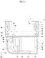
Fig. 3 is a view of the interior of an indoor unit and the refrigeration unit body according to the embodiment of the present disclosure as seen from above. -
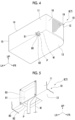
Fig. 4 is a perspective view of the refrigeration unit body according to the embodiment of the present disclosure as seen from below. -
Fig. 5 is a perspective view showing a state in which a back opening according to the embodiment of the present disclosure is closed by a decorative board. -
Fig. 6 is a schematic view showing a case where a casing of the refrigeration unit body according to the embodiment of the present disclosure is attached to a ceiling wall of a trailer body. -
Fig. 7 is a perspective view showing a state in which a lower opening according to the embodiment of the present disclosure is closed by the decorative board. Description of Embodiments - Hereinafter, a refrigerated
vehicle 1 according to an embodiment of the present disclosure will be described with reference toFigs. 1 to 6 . - As shown in
Fig. 1 , the refrigeratedvehicle 1 includes atractor 2, a trailer 3, and atransport refrigeration unit 7. - Hereinafter, a vertical up-down direction will be simply referred to as an "up-down direction", one of directions perpendicular to the up-down direction will be referred to as a "front-rear direction", and a direction perpendicular to the up-down direction and the front-rear direction will be referred to as a "left-right direction". A running direction of the refrigerated
vehicle 1 coincides with the front-rear direction. The front, the rear, the left, and the right are defined with reference to a driver's seat of the refrigeratedvehicle 1. - The
tractor 2 includes acab 4 serving as the driver's seat and runs by means of a running engine (not shown). Thetractor 2 tows the trailer 3. - The trailer 3 includes a
trailer body 5 and achassis 6. - The
trailer body 5 is a box-shaped container supported from below by thechassis 6. Thetrailer body 5 extends in the front-rear direction. A space for accommodating a cargo (not shown) is formed inside thetrailer body 5. - The
trailer body 5 has afront wall 5a disposed on thetractor 2 side, aceiling wall 5b connected to an upper end of thefront wall 5a, aleft wall 5c connected to a left end of thefront wall 5a and a left end of theceiling wall 5b, and aright wall 5d connected to a right end of thefront wall 5a and a right end of theceiling wall 5b. - The
transport refrigeration unit 7 has arefrigeration unit body 8 and anindoor unit 9. - The
refrigeration unit body 8 is disposed outside thetrailer body 5. Therefrigeration unit body 8 is fixed to an upper portion of a front surface of thefront wall 5a of thetrailer body 5. As shown inFigs. 2 to 5 , therefrigeration unit body 8 includes acasing 10, anaccumulator 53, acompressor 51, afan 40, anoutdoor heat exchanger 52, areceiver 54, an electrical component box 20, and adecorative board 83. A space for accommodating devices configuring therefrigeration unit body 8 is formed inside thecasing 10. - As shown in
Fig. 3 , theindoor unit 9 includes anexpansion valve 55, anindoor heat exchanger 56, and anindoor fan 57. - A
cooling cycle 50 of thetransport refrigeration unit 7 is configured by theaccumulator 53, thecompressor 51, theoutdoor heat exchanger 52, thereceiver 54, theexpansion valve 55, theindoor heat exchanger 56, theindoor fan 57, and the like. - The
accumulator 53 is accommodated in thecasing 10. Theaccumulator 53 is connected to theindoor heat exchanger 56 in a state in which theaccumulator 53 is capable of receiving a refrigerant passing through theindoor heat exchanger 56. - The
compressor 51 is accommodated in thecasing 10 and is connected to theaccumulator 53. Thecompressor 51 compresses a gas-phase refrigerant supplied from theaccumulator 53. - The
fan 40 is accommodated in thecasing 10. Thefan 40 takes air into thecasing 10 and discharges the air in thecasing 10 to the outside. - The
outdoor heat exchanger 52 is accommodated in thecasing 10. Theoutdoor heat exchanger 52 is connected to thecompressor 51 in a state in which theoutdoor heat exchanger 52 is capable of receiving the refrigerant compressed by thecompressor 51. Theoutdoor heat exchanger 52 is a condenser that cools and condenses the gas-phase refrigerant supplied from thecompressor 51 by using the outside air taken into thecasing 10 by thefan 40. The gas-phase refrigerant supplied from thecompressor 51 is changed to a liquid-phase refrigerant by theoutdoor heat exchanger 52. Theoutdoor heat exchanger 52 is connected to thereceiver 54 in a state in which the cooled refrigerant can be supplied to thereceiver 54. - The
receiver 54 is accommodated in thecasing 10. Thereceiver 54 temporarily stores the liquid-phase refrigerant supplied from theoutdoor heat exchanger 52, and absorbs a fluctuation in flow rate of the refrigerant in thecooling cycle 50. Thereceiver 54 is connected to theexpansion valve 55 in a state in which the stored liquid-phase refrigerant can be supplied. - The
expansion valve 55 is accommodated in thetrailer body 5. Theexpansion valve 55 is provided one by one on the left side and the right side in thetrailer body 5. The twoexpansion valves 55 are disposed at positions symmetrical when viewed from above, and have the same configuration. Hereinafter, theleft expansion valve 55 of the twoexpansion valves 55 will be described, and theright expansion valve 55 will not be described. - The
expansion valve 55 is disposed in an upper portion (a portion close to theceiling wall 5b) of a corner formed by theleft wall 5c and thefront wall 5a. Theexpansion valve 55 expands (decompresses) the liquid-phase refrigerant supplied from thereceiver 54. Theexpansion valve 55 is connected to theindoor heat exchanger 56 in a state in which the expanded liquid-phase refrigerant can be supplied to theindoor heat exchanger 56. - The
indoor heat exchanger 56 is accommodated in thetrailer body 5. Theindoor heat exchanger 56 is provided one by one on the left side and the right side in thetrailer body 5. The twoindoor heat exchangers 56 are disposed at positions symmetrical when viewed from above, and have the same configuration. Hereinafter, theindoor heat exchanger 56 on the left side of the twoindoor heat exchangers 56 will be described, and theindoor heat exchanger 56 on the right side will not be described. - The
indoor heat exchanger 56 is disposed near theexpansion valve 55. Theindoor heat exchanger 56 is an evaporator that exchanges heat between the air around theindoor heat exchanger 56 and the liquid-phase refrigerant supplied from theexpansion valve 55 to evaporate the liquid-phase refrigerant. The gas-phase refrigerant supplied from theexpansion valve 55 is changed to the liquid-phase refrigerant by theindoor heat exchanger 56. At this time, heat of the air around theindoor heat exchanger 56 is absorbed to the refrigerant. In this way, the air around theindoor heat exchanger 56 is cooled. - The
indoor fan 57 is accommodated in thetrailer body 5. Theindoor fan 57 is provided one by one on the left side and the right side in thetrailer body 5. The twoindoor fans 57 are disposed at positions symmetrical when viewed from above, and have the same configuration. Hereinafter, theindoor fan 57 on the left side of the twoindoor fans 57 will be described, and theindoor fan 57 on the right side will not be described. - The
indoor fan 57 is disposed near theindoor heat exchanger 56. Theindoor fan 57 circulates the air cooled by theindoor heat exchanger 56 inside thetrailer body 5 to cool the inside of thetrailer body 5. - Hereinafter, details of the
refrigeration unit body 8 will be described with reference toFigs. 2 to 5 . - As shown in
Figs. 2 to 4 , thecasing 10 is formed in a cubic shape. Thecasing 10 includes aback plate 11 that is attachable to the trailer 3, afront plate 12 disposed to face theback plate 11 from the front, alower plate 13 connected to lower ends of theback plate 11 and thefront plate 12 and attachable to the trailer 3 in the same manner as theback plate 11, anupper plate 14 connected to an upper end of thefront plate 12 of theback plate 11, and aleft plate 15 and aright plate 16 that are disposed to face each other in the left-right direction and are connected to theback plate 11, thefront plate 12, thelower plate 13, and theupper plate 14. - The
casing 10 is formed to be thin in the up-down direction. Thecasing 10 is formed such that a height in the up-down direction is, for example, a ratio of 50% or less with respect to a width in the left-right direction and a depth in the front-rear direction. - In the present embodiment, the
back plate 11 is attached and fixed to the front surface of thefront wall 5a of thetrailer body 5. - The
lower plate 13 extends forward from the lower end of theback plate 11. A plate thickness direction of thelower plate 13 coincides with the up-down direction. Thelower plate 13 is formed integrally with theback plate 11 and is formed in an L-shape together with theback plate 11 when viewed from the left-right direction. Thelower plate 13 functions as a main frame that supports an accommodated object in thecasing 10 together with theback plate 11. - A plate thickness direction of the
upper plate 14 coincides with the up-down direction. Theupper plate 14 is provided with twodischarge ports 14a penetrating theupper plate 14 and discharging the air from the inside to the outside of thecasing 10. The twodischarge ports 14a are provided on the left side and the right side of theupper plate 14. Thedischarge port 14a penetrates theupper plate 14 in the up-down direction. Thedischarge port 14a is formed in a circular shape when viewed from the up-down direction. - The
front plate 12 and theright plate 16 are provided with asuction port 19 through which the air outside thecasing 10 is introduced into thecasing 10. Thesuction port 19 is formed in an L-shape when viewed from the up-down direction, and extends continuously from thefront plate 12 to theright plate 16. Thesuction port 19 penetrates thefront plate 12 and theright plate 16. In addition, a wire mesh is mounted to the suction port 19 (refer toFig. 2 ). In addition, anopening 80 that allows the inside and the outside of thecasing 10 to communicate with each other is provided in a lower portion of thecasing 10. - The
opening 80 allows a pipe P or a wire W of the accommodated object in thecasing 10 to be drawn out of thecasing 10. Theopening 80 is provided across theback plate 11 and thelower plate 13 of thecasing 10. In addition, theopening 80 is provided on the right side of thecasing 10. Theopening 80 extends in the left-right direction. That is, a longitudinal direction of theopening 80 coincides with the left-right direction. - In addition, in each of the drawings, only one pipe P and one wire W are schematically shown. The number of the pipes P and the wires W can be appropriately changed.
- The
opening 80 has aback opening 81 located on theback plate 11 side and alower opening 82 located on thelower plate 13 side and connected to a lower end of theback opening 81, and is formed in an L-shape when viewed from the left-right direction. Both theback opening 81 and thelower opening 82 are formed in a rectangular shape of which a longitudinal direction is the left-right direction when viewed from a penetration direction. Thelower opening 82 is smaller than theback opening 81. - The pipe P and the wire W are drawn out from any one of the
back opening 81 and thelower opening 82. As shown inFig. 5 , one of theback opening 81 and thelower opening 82, which is not used for drawing out the pipe P and the wire W, is closed by thedecorative board 83. - The
decorative board 83 is formed in a thin plate shape larger than theback opening 81 and thelower opening 82. Thedecorative board 83 is disposed to cover theopening 80 from the outside of thecasing 10. Thedecorative board 83 is, for example, fastened and fixed to thecasing 10 by bolts. - As shown in
Fig. 3 , thecasing 10 described above accommodates theaccumulator 53, thecompressor 51, thereceiver 54, the electrical component box 20, theoutdoor heat exchanger 52, and thefan 40. More specifically, theaccumulator 53, thecompressor 51, and thereceiver 54 are provided in a space on the right side in thecasing 10. The electrical component box 20 is provided in a space on the left side in thecasing 10. In addition, theoutdoor heat exchanger 52 is provided at a position facing thesuction port 19 in thecasing 10, and thefan 40 is provided at a position facing thedischarge port 14a in thecasing 10. - A space capable of accommodating various devices is formed inside the electrical component box 20. The electrical components (not shown) such as a power supply such as an inverter or a converter, and a power drive system component are accommodated in the electrical component box 20. The electrical component box 20 is provided on the left side from the
opening 80 of thecasing 10. - The electrical component box 20 is formed in a cubic shape. The electrical component box 20 is fixed to the
casing 10 by a fixing member (not shown) in a state in which a back surface and a lower surface thereof are separated from theback plate 11 and thelower plate 13 of thecasing 10, respectively. An upper surface of the electrical component box 20 is separated downward from theupper plate 14 of thecasing 10 toward the front. - The
compressor 51 is provided on the left side from theopening 80 of thecasing 10 and on the right side from the electrical component box 20. That is, a position of theopening 80 of thecasing 10 in the left-right direction is different from those of thecompressor 51 and the electrical component box 20. Thecompressor 51 is disposed to extend in the up-down direction. - The
outdoor heat exchanger 52 is provided between the electrical component box 20 and thesuction port 19. Theoutdoor heat exchanger 52 is formed in the same shape as thesuction port 19 when viewed from the up-down direction. Theoutdoor heat exchanger 52 is formed in, for example, an L-shape when viewed from the up-down direction. Theoutdoor heat exchanger 52 exchanges heat between the air introduced from thesuction port 19 and the refrigerant flowing through the coolingcycle 50. - The
fan 40 is provided one by one at positions facing the twodischarge ports 14a of thecasing 10 so that twofans 40 are provided in total. An axial direction of thefan 40 coincides with the up-down direction. - When the
fan 40 is operated, the air outside thecasing 10 is introduced into thecasing 10 from thesuction port 19. In this manner, the air is supplied to theoutdoor heat exchanger 52. The air that has exchanged heat with the refrigerant in theoutdoor heat exchanger 52 passes through thefan 40 and thedischarge port 14a and is discharged to the outside of thecasing 10. - In the
transport refrigeration unit 7 described above, thecasing 10 of therefrigeration unit body 8 is attached by the following procedure. - As shown in
Fig. 1 , a case where thecasing 10 is attached to thefront wall 5a of thetrailer body 5 will be described. - First, the pipe P and the wire W in the
casing 10 are drawn out of the outside of thecasing 10 through thelower opening 82 of theopening 80. Subsequently, thedecorative board 83 is attached to theback plate 11 from the outside of thecasing 10 to close theback opening 81 of the opening 80 (refer toFig. 5 ). - Thereafter, the
back plate 11 of thecasing 10 is fixed to thefront wall 5a of thetrailer body 5. The pipe P and the wire W drawn out from the inside of thecasing 10 are connected to a pipe and a wire (not shown) inside thetrailer body 5. - In this way, the
casing 10 is attached. - In addition, as shown in
Fig. 6 , thecasing 10 may be attached to theceiling wall 5b of thetrailer body 5. In this case, the pipe P and the wire W are drawn out through theback opening 81 of theopening 80, and thelower plate 13 of thecasing 10 is fixed to theceiling wall 5b of thetrailer body 5. - In this case, as shown in
Fig. 7 , thelower opening 82 of theopening 80 is closed by thedecorative board 83. - In the present embodiment, the
casing 10 is provided with theopening 80 that is provided across theback plate 11 and thelower plate 13, that allows the inside and the outside of thecasing 10 to communicate with each other, and that allows the pipe P and the wiring W to be drawn out. Theopening 80 includes theback opening 81 located on theback plate 11 side and thelower opening 82 located on thelower plate 13 side and communicating with the lower end of theback opening 81. - Accordingly, the pipe P and the wire W can be drawn out of the
casing 10 from both theback plate 11 and thelower plate 13 of thecasing 10 by oneopening 80. Therefore, it is possible to select whether to attach thecasing 10 to thefront wall 5a of the trailer body 5 (refer toFig. 1 ) or to attach thecasing 10 to theceiling wall 5b of the trailer body 5 (refer toFig. 6 ) without changing the posture of thecasing 10. In addition, in a case where thecasing 10 is attached to thefront wall 5a of thetrailer body 5, it is possible to select whether to dispose thecasing 10 in a horizontal direction or to dispose thecasing 10 in a vertical direction. Similarly, even in a case where thecasing 10 is attached to theceiling wall 5b of thetrailer body 5, it is possible to select the attachment posture of thecasing 10 as in a case where thecasing 10 is attached to thefront wall 5a. Therefore, for example, the degree of freedom in attachment can be improved as compared with a case where openings for drawing out the pipe P and the wiring W are separately formed in theback plate 11 and thelower plate 13 of thecasing 10. - In addition, since the
back opening 81 and thelower opening 82 communicate with each other, theback opening 81 and thelower opening 82 can be formed in one process. Therefore, a manufacturing process of thecasing 10 can be simplified. That is, a manufacturing process of thetransport refrigeration unit 7 can be simplified. - In the present embodiment, the
decorative board 83 that closes any one of theback opening 81 and thelower opening 82 is further provided. - Accordingly, one of the
back opening 81 and thelower opening 82, which is not used for drawing out the pipe P or the wire W, can be closed by thedecorative board 83. Therefore, it is possible to prevent the outside air from flowing into thecasing 10 through theopening 80. - In addition, since an attachment area of the
casing 10 can be increased by thedecorative board 83, an attachment stability of thecasing 10 can be improved. - In addition, the inside of the
casing 10 can be prevented from being visible from the outside by thedecorative board 83. Therefore, designability can be improved. - In the present embodiment, the position of the
opening 80 in the left-right direction is different from those of the electrical component box 20 and thecompressor 51. - Accordingly, in the
casing 10, theopening 80 can be formed at a position separated from a position where a load of a heavy object such as the electrical component box 20 or thecompressor 51 is applied. Therefore, an attachment strength of thecasing 10 can be improved. - In the present embodiment, the longitudinal direction of the
opening 80 coincides with the left-right direction. - Accordingly, it is possible to prevent the
opening 80 from lengthening in the up-down direction while securing the size of theopening 80 necessary for drawing out the pipe P and the wire W. Therefore, in a case where thecasing 10 is attached at theback plate 11, the attachment strength of thecasing 10 can be improved. - In addition, the
casing 10 can be easily formed to be thin in the up-down direction while maintaining the attachment strength of thecasing 10 at theback plate 11. Therefore, it is possible to form thecasing 10 so as to reduce air resistance received by thecasing 10 when therefrigerated vehicle 1 runs. - In the present embodiment, the
lower opening 82 is smaller than theback opening 81. - Accordingly, the size of the
lower opening 82 can be reduced while securing the size of theopening 80 necessary for drawing out the pipe P or the wire W. Therefore, the strength of thelower plate 13 of thecasing 10 where a load of the accommodated object in thecasing 10 is directly applied can be improved. - The embodiment of the present disclosure has been described in detail with reference to the drawings hereinbefore. However, the specific configuration is not limited to the embodiment, and includes design changes and the like within a scope not departing from the gist of the present disclosure.
- In the above embodiment, a case where the pipe P and the wire W are drawn out from the
opening 80 of thecasing 10 has been described. However, the present disclosure is not limited thereto. Any one of the pipe P and the wire W may be drawn out from theopening 80. - In the above embodiment, the
decorative board 83 is fixed to thecasing 10 by bolts. However, the present disclosure is not limited thereto. Thedecorative board 83 may be fitted to theopening 80 to close theopening 80. In addition, for example, thedecorative board 83 may be attached by a hinge such that theopening 80 is openable and closable. - The
transport refrigeration unit 7 described in each embodiment is understood, for example, as follows. -
- (1) A
transport refrigeration unit 7 according to a first aspect includes acasing 10 that includes aback plate 11 attachable to a trailer 3, and alower plate 13 extending forward from a lower end of theback plate 11 and attachable to the trailer 3, and that is capable of storing various devices therein, in which anopening 80 provided across theback plate 11 and thelower plate 13 is formed in thecasing 10, and theopening 80 allows an inside and an outside of thecasing 10 to communicate with each other and allows at least one of a pipe P and a wire W to be drawn out of thecasing 10, and theopening 80 includes aback opening 81 located on aback plate 11 side and alower opening 82 located on alower plate 13 side and connected to a lower end of theback opening 81. - Accordingly, the pipe P or the wire W can be drawn out of the
casing 10 from both theback plate 11 and thelower plate 13 of thecasing 10 by oneopening 80. - (2) The
transport refrigeration unit 7 according to a second aspect is thetransport refrigeration unit 7 of (1), which may further include adecorative board 83 that closes any one of theback opening 81 and thelower opening 82. - Accordingly, one of the
back opening 81 and thelower opening 82, which is not used for drawing out the pipe P or the wire W, can be closed by thedecorative board 83. - (3) The
transport refrigeration unit 7 according to a third aspect is thetransport refrigeration unit 7 of (1) or (2), which may further include an electrical component box 20 that is provided in thecasing 10 and that accommodates electrical components; and acompressor 51 that is provided in thecasing 10, in which a position of theopening 80 in a left-right direction may be different from those of the electrical component box 20 and thecompressor 51. - Accordingly, in the
casing 10, theopening 80 can be formed at a position separated from a position where a load of a heavy object such as the electrical component box 20 or thecompressor 51 is applied. - (4) The
transport refrigeration unit 7 according to a fourth aspect is thetransport refrigeration unit 7 according to any one of (1) to (3), in which a longitudinal direction of theopening 80 may coincide with a left-right direction. - Accordingly, it is possible to prevent the
opening 80 from lengthening in the up-down direction while securing the size of theopening 80 necessary for drawing out the pipe P or the wire W. - (5) The
transport refrigeration unit 7 according to a fifth aspect is thetransport refrigeration unit 7 according to any one of (1) to (4), in which thelower opening 82 may be smaller than theback opening 81. - Accordingly, the size of the
lower opening 82 can be reduced while securing the size of theopening 80 necessary for drawing out the pipe P or the wire W. - The present disclosure relates to a transport refrigeration unit. According to the present disclosure, the degree of freedom in attachment can be improved.
-
- 1:
- refrigerated vehicle
- 2:
- tractor
- 3:
- trailer
- 4:
- cab
- 5:
- trailer body
- 5a:
- front wall
- 5b:
- ceiling wall
- 5c:
- left wall
- 5d:
- right wall
- 6:
- chassis
- 7:
- transport refrigeration unit
- 8:
- refrigeration unit body
- 9:
- indoor unit
- 10:
- casing
- 11:
- back plate
- 12:
- front plate
- 13:
- lower plate
- 14:
- upper plate
- 14a:
- discharge port
- 15:
- left plate
- 16:
- right plate
- 19:
- suction port
- 20:
- electrical component box
- 40:
- fan
- 50:
- cooling cycle
- 51:
- compressor
- 52:
- outdoor heat exchanger
- 53:
- accumulator
- 54:
- receiver
- 55:
- expansion valve
- 56:
- indoor heat exchanger
- 57:
- indoor fan
- 80:
- opening
- 81:
- back opening
- 82:
- lower opening
- 83:
- decorative board
- P:
- pipe
- W:
- wire
Claims (5)
- A transport refrigeration unit comprising:a casing that includes a back plate attachable to a trailer, and a lower plate extending forward from a lower end of the back plate and attachable to the trailer, and that is capable of storing various devices therein,wherein an opening provided across the back plate and the lower plate is formed in the casing, and the opening allows an inside and an outside of the casing to communicate with each other and allows at least one of a pipe and a wire to be drawn out of the casing, andthe opening includes a back opening located on a back plate side and a lower opening located on a lower plate side and connected to a lower end of the back opening.
- The transport refrigeration unit according to Claim 1, further comprising a decorative board that closes any one of the back opening and the lower opening.
- The transport refrigeration unit according to Claim 1 or 2, further comprising:an electrical component box that is provided in the casing and that accommodates electrical components; anda compressor that is provided in the casing,wherein a position of the opening in a left-right direction is different from those of the electrical component box and the compressor.
- The transport refrigeration unit according to any one of Claims 1 to 3,
wherein a longitudinal direction of the opening coincides with a left-right direction. - The transport refrigeration unit according to any one of Claims 1 to 4,
wherein the lower opening is smaller than the back opening.
Applications Claiming Priority (1)
| Application Number | Priority Date | Filing Date | Title |
|---|---|---|---|
| PCT/JP2021/039916 WO2023073892A1 (en) | 2021-10-28 | 2021-10-28 | Transport refrigerator unit |
Publications (2)
| Publication Number | Publication Date |
|---|---|
| EP4407259A1 true EP4407259A1 (en) | 2024-07-31 |
| EP4407259A4 EP4407259A4 (en) | 2024-12-11 |
Family
ID=86157574
Family Applications (1)
| Application Number | Title | Priority Date | Filing Date |
|---|---|---|---|
| EP21962438.4A Pending EP4407259A4 (en) | 2021-10-28 | 2021-10-28 | TRANSPORT REFRIGERATOR UNIT |
Country Status (3)
| Country | Link |
|---|---|
| EP (1) | EP4407259A4 (en) |
| JP (1) | JPWO2023073892A1 (en) |
| WO (1) | WO2023073892A1 (en) |
Families Citing this family (1)
| Publication number | Priority date | Publication date | Assignee | Title |
|---|---|---|---|---|
| JP2025158852A (en) * | 2024-04-05 | 2025-10-17 | 三菱重工サーマルシステムズ株式会社 | Transport refrigeration equipment |
Family Cites Families (8)
| Publication number | Priority date | Publication date | Assignee | Title |
|---|---|---|---|---|
| JPS5754547Y2 (en) * | 1978-06-20 | 1982-11-25 | ||
| JPS616166U (en) * | 1984-06-14 | 1986-01-14 | 三洋電機株式会社 | On-vehicle refrigerator |
| US5222373A (en) * | 1992-09-16 | 1993-06-29 | Thermo King Corporation | Transport refrigeration condenser unit suitable for horizontal and vertical mounting |
| JP2002310459A (en) * | 2001-04-11 | 2002-10-23 | Sharp Corp | Air conditioner |
| JP2012220075A (en) * | 2011-04-07 | 2012-11-12 | Mitsubishi Electric Corp | Indoor unit of air conditioner |
| JP6718697B2 (en) * | 2016-03-02 | 2020-07-08 | サッポロビール株式会社 | Beverage server |
| US10830521B2 (en) * | 2016-05-04 | 2020-11-10 | Carrier Corporation | Refrigeration unit having movable directional element |
| JP7137334B2 (en) * | 2018-03-29 | 2022-09-14 | 三菱重工サーマルシステムズ株式会社 | Refrigerator unit for cold storage vehicle |
-
2021
- 2021-10-28 JP JP2023556004A patent/JPWO2023073892A1/ja active Pending
- 2021-10-28 WO PCT/JP2021/039916 patent/WO2023073892A1/en not_active Ceased
- 2021-10-28 EP EP21962438.4A patent/EP4407259A4/en active Pending
Also Published As
| Publication number | Publication date |
|---|---|
| JPWO2023073892A1 (en) | 2023-05-04 |
| EP4407259A4 (en) | 2024-12-11 |
| WO2023073892A1 (en) | 2023-05-04 |
Similar Documents
| Publication | Publication Date | Title |
|---|---|---|
| CN109693597B (en) | Electric vehicle | |
| CN112140838B (en) | Vehicle-mounted air conditioner and vehicle | |
| JP5453943B2 (en) | Trailer refrigeration equipment | |
| EP3093587A1 (en) | Transportation refrigeration unit and trailer | |
| CN112140841B (en) | Vehicle air conditioner and vehicle | |
| JP2000213849A (en) | Refrigerated transport vehicle | |
| JP7211289B2 (en) | In-vehicle air conditioner | |
| US7318469B2 (en) | Piping structure for refrigerant cycle system of vehicle | |
| JP7137334B2 (en) | Refrigerator unit for cold storage vehicle | |
| WO2023073892A1 (en) | Transport refrigerator unit | |
| TWI568639B (en) | Equipment for the installation of refrigerators for foodstuffs on ships and for the installation of refrigerators on ships | |
| JP4916464B2 (en) | Refrigeration equipment for vehicles | |
| JP5706819B2 (en) | Trailer refrigeration equipment | |
| EP4407258A1 (en) | Transport refrigeration unit | |
| JP5476805B2 (en) | Trailer refrigeration equipment | |
| EP3044126A1 (en) | Refrigerated container assembly | |
| JP7642090B2 (en) | Transport refrigeration unit | |
| EP4394288B1 (en) | Transport refrigeration unit | |
| CN223726662U (en) | Vehicle-mounted refrigerator and transportation carrier | |
| JP3342641B2 (en) | Refrigeration equipment for refrigerator cars | |
| JP7528765B2 (en) | Vehicle Refrigeration Unit | |
| JP2002267334A (en) | Refrigerating system for overland transportation | |
| JP2010261625A (en) | Cargo compartment structure of vehicle | |
| CN121848893A (en) | Vehicle-mounted air conditioner | |
| JP2017172892A (en) | Outdoor refrigerator |
Legal Events
| Date | Code | Title | Description |
|---|---|---|---|
| STAA | Information on the status of an ep patent application or granted ep patent |
Free format text: STATUS: THE INTERNATIONAL PUBLICATION HAS BEEN MADE |
|
| PUAI | Public reference made under article 153(3) epc to a published international application that has entered the european phase |
Free format text: ORIGINAL CODE: 0009012 |
|
| STAA | Information on the status of an ep patent application or granted ep patent |
Free format text: STATUS: REQUEST FOR EXAMINATION WAS MADE |
|
| 17P | Request for examination filed |
Effective date: 20240422 |
|
| AK | Designated contracting states |
Kind code of ref document: A1 Designated state(s): AL AT BE BG CH CY CZ DE DK EE ES FI FR GB GR HR HU IE IS IT LI LT LU LV MC MK MT NL NO PL PT RO RS SE SI SK SM TR |
|
| A4 | Supplementary search report drawn up and despatched |
Effective date: 20241108 |
|
| RIC1 | Information provided on ipc code assigned before grant |
Ipc: B60H 1/32 20060101ALI20241105BHEP Ipc: B60H 1/00 20060101ALI20241105BHEP Ipc: F25D 19/00 20060101ALI20241105BHEP Ipc: F25D 11/00 20060101AFI20241105BHEP |
|
| DAV | Request for validation of the european patent (deleted) | ||
| DAX | Request for extension of the european patent (deleted) |