EP4407236A1 - Rotor for gas hob control - Google Patents
Rotor for gas hob control Download PDFInfo
- Publication number
- EP4407236A1 EP4407236A1 EP24151001.5A EP24151001A EP4407236A1 EP 4407236 A1 EP4407236 A1 EP 4407236A1 EP 24151001 A EP24151001 A EP 24151001A EP 4407236 A1 EP4407236 A1 EP 4407236A1
- Authority
- EP
- European Patent Office
- Prior art keywords
- arm section
- ring body
- collar
- rotor device
- rotor
- Prior art date
- Legal status (The legal status is an assumption and is not a legal conclusion. Google has not performed a legal analysis and makes no representation as to the accuracy of the status listed.)
- Granted
Links
Images


Classifications
-
- F—MECHANICAL ENGINEERING; LIGHTING; HEATING; WEAPONS; BLASTING
- F24—HEATING; RANGES; VENTILATING
- F24C—DOMESTIC STOVES OR RANGES ; DETAILS OF DOMESTIC STOVES OR RANGES, OF GENERAL APPLICATION
- F24C3/00—Stoves or ranges for gaseous fuels
- F24C3/12—Arrangement or mounting of control or safety devices
- F24C3/126—Arrangement or mounting of control or safety devices on ranges
-
- F—MECHANICAL ENGINEERING; LIGHTING; HEATING; WEAPONS; BLASTING
- F16—ENGINEERING ELEMENTS AND UNITS; GENERAL MEASURES FOR PRODUCING AND MAINTAINING EFFECTIVE FUNCTIONING OF MACHINES OR INSTALLATIONS; THERMAL INSULATION IN GENERAL
- F16K—VALVES; TAPS; COCKS; ACTUATING-FLOATS; DEVICES FOR VENTING OR AERATING
- F16K3/00—Gate valves or sliding valves, i.e. cut-off apparatus with closing members having a sliding movement along the seat for opening and closing
- F16K3/02—Gate valves or sliding valves, i.e. cut-off apparatus with closing members having a sliding movement along the seat for opening and closing with flat sealing faces; Packings therefor
- F16K3/04—Gate valves or sliding valves, i.e. cut-off apparatus with closing members having a sliding movement along the seat for opening and closing with flat sealing faces; Packings therefor with pivoted closure members
- F16K3/06—Gate valves or sliding valves, i.e. cut-off apparatus with closing members having a sliding movement along the seat for opening and closing with flat sealing faces; Packings therefor with pivoted closure members in the form of closure plates arranged between supply and discharge passages
- F16K3/08—Gate valves or sliding valves, i.e. cut-off apparatus with closing members having a sliding movement along the seat for opening and closing with flat sealing faces; Packings therefor with pivoted closure members in the form of closure plates arranged between supply and discharge passages with circular plates rotatable around their centres
-
- F—MECHANICAL ENGINEERING; LIGHTING; HEATING; WEAPONS; BLASTING
- F16—ENGINEERING ELEMENTS AND UNITS; GENERAL MEASURES FOR PRODUCING AND MAINTAINING EFFECTIVE FUNCTIONING OF MACHINES OR INSTALLATIONS; THERMAL INSULATION IN GENERAL
- F16K—VALVES; TAPS; COCKS; ACTUATING-FLOATS; DEVICES FOR VENTING OR AERATING
- F16K37/00—Special means in or on valves or other cut-off apparatus for indicating or recording operation thereof, or for enabling an alarm to be given
- F16K37/0025—Electrical or magnetic means
- F16K37/0041—Electrical or magnetic means for measuring valve parameters
-
- G—PHYSICS
- G05—CONTROLLING; REGULATING
- G05G—CONTROL DEVICES OR SYSTEMS INSOFAR AS CHARACTERISED BY MECHANICAL FEATURES ONLY
- G05G1/00—Controlling members, e.g. knobs or handles; Assemblies or arrangements thereof; Indicating position of controlling members
- G05G1/08—Controlling members for hand actuation by rotary movement, e.g. hand wheels
- G05G1/10—Details, e.g. of discs, knobs, wheels or handles
- G05G1/12—Means for securing the members on rotatable spindles or the like
-
- H—ELECTRICITY
- H01—ELECTRIC ELEMENTS
- H01H—ELECTRIC SWITCHES; RELAYS; SELECTORS; EMERGENCY PROTECTIVE DEVICES
- H01H3/00—Mechanisms for operating contacts
- H01H3/02—Operating parts, i.e. for operating driving mechanism by a mechanical force external to the switch
- H01H3/16—Operating parts, i.e. for operating driving mechanism by a mechanical force external to the switch adapted for actuation at a limit or other predetermined position in the path of a body, the relative movement of switch and body being primarily for a purpose other than the actuation of the switch, e.g. for a door switch, a limit switch, a floor-levelling switch of a lift
Definitions
- the present invention relates to a rotor device for a gas hob control arrangement.
- the present invention also relates to a gas hob control arrangement with such a rotor device.
- One type of gas hob control arrangement has a single handle as a user interface.
- the user can adjust a gas flow to a burner by turning the handle. Further, the user can ignite the gas at the burner by pressing the handle.
- the rotor device serves as an angle-independent actuator for an ignition switch device.
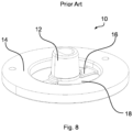
- Fig. 8 shows a prior art rotor device 10 having a hub 12 for receiving a shaft (not shown) and a ring body 14.
- the hub 12 is connected to the ring body 14 via beams 16 thereby forming drainage passages 18.
- a return spring (not shown) abuts a lower face of the hub 12 for urging the rotor device 10 upwards.
- the return spring is to be accommodated partly in the hub 12. This would increase a diameter of the hub 12 which in return would reduce a size of the drainage passage 18.
- a different approach is sought for.
- the rotor device has a collar, a ring body, and at least on arm.
- the collar forms an opening.
- the collar is configured to transfer a rotating and/or translating movement between the rotor device and a shaft device, which is receivable in the opening.
- the ring body has a larger inner diameter than a width of the opening.
- the at least one arm comprises an outer arm section, an inner arm section, and a central arm section.
- the outer arm section extends from the ring body radially inwards.
- the inner arm section extends from the collar radially outwards.
- the central arm section extends from a radially inner end of the outer arm section axially to a radially outer end of the inner arm section.
- a shaft device is receivable in the opening of the collar, and when a shaft device is received in the opening of the collar, then a rotating and/or translating movement is transferable between the collar and the received shaft device.
- the outer arm section protrudes radially inwards from an inner peripheral surface of the ring body.
- the inner arm section protrudes radially outwards from an outer peripheral surface of the collar.
- the one or more arms are forming a loop to the collar, which is placed at a different level along a central axis than the ring body. This loop allows for a more compact configuration of a resulting gas hob control arrangement. Further, as the collar is held to the ring body only by means of the one or more arms, there are formed one or more drainage passages in between. Thus, a satisfying drainage behavior is achieved.
- inner arm section and outer arm section are names meant for easier discrimination.
- the collar preferably is smaller than the ring body, the arm section, which protrudes from the collar is referred to as the inner arm section.
- the arm section, which protrudes from the preferably larger ring body is the outer arm section.
- an inner end of the outer arm section will in most case be closer to a central axis than an outer end of the inner arm section.
- arms are not restricted in general, a symmetrical arrangement is preferred. For example, two arms with a relative spacing of 180° around the central axis, or three arms with a relative spacing of 120° around the central axis are preferred variants.
- the rotor device has two or more arms, these arms preferable are shaped identical for endurance reasons.
- the three arm sections may consecutively follow a path.
- the number of arm sections per arm can be limited to an easy-to-manufacture configuration.
- the arm sections may extend linearly. Thus, a bending behavior of the arm sections can easily be predetermined. However, at least one arm section may extend along a curve when viewed in a side view, in order to provide an adjustable bending behavior.
- the arm sections are connected by sharp intersections. That is, the arm sections may follow a z-path. This option allows for fast drainage.
- the arm sections merge with rounded edges. That is, the arm sections may follow a s-path. This option minimizes residue adherence.
- each arm section has a constant width along its path. This option provides a constant stiffness of the respective arm.
- At least one of the three arm sections has a varying width along its path. This option allows for increased damping behavior.
- the outer arm section has a declined surface on a collar-side. That is, a side oriented towards the collar instead of away from the collar preferably has a roof-shaped top surface. In other words, a prism-shaped cross section is suggested. This option facilitates running off of any liquids from the arm section top side.
- the rotor device may be integrally formed for increased strength.
- Preferred materials comprise metal alloys and plastic materials.
- At least one arm section may have a declined top surface, when the collar is positioned above the ring body in a mounted position. That is, the relative position of the collar relative to the ring body defines an upwards direction.
- the at least one arm section has a downwards inclined top surface, liquids easier run down from this arm section.
- a radius from a rotation axis of the rotor device to an inner end of the outer arm section or to every inner end of the outer arm sections may be larger than the width of the opening of the collar. This allows for an installation space for a spring device, which encompasses a shaft device.
- the collar may have a front face facing towards the ring body.
- the front face is a preferred bearing surface for a spring device.
- the rotor device has a hollow-cylindrical space in an empty space, that is defined by an axially parallel projection of the opening in the collar, inner faces and/or edges of the arm sections, a front face of the collar facing towards the ring body, and a front face of the ring body facing away from the collar.
- a ring-shaped spring device like a coils spring or a bellows-shaped arrangement of disc springs can reliably be accommodated.
- the inner arm section may extend both radially outwards from the collar and axially away from the ring body. That is, it may be inclined such that it extends both radially outwards from the collar and axially away from the ring body. This results in an elastic behavior of the arm(s), which is desired for some applications.
- Elasticity, flexibility and/or bending of the arm(s) has the advantage that small misalignments between the shaft device and other parts of the gas hub control arrangement can be self-compensated by the arm behavior.
- the inner arm section may extend both radially outwards from the collar and axially towards the ring body, wherein an angle between the rotation axis of the rotor device and the inner arm section is larger than an angle between the rotation axis and the central arm section. That is, the inner arm section may be inclined such that it extends both radially outwards from the collar and axially towards the ring body.
- the central arm section may extend both axially away from the ring body and radially outwards. That is, the central arm section may be inclined outwards / declined inwards.
- the rotor device according to any of the above variants may be provided as a backfitting part for improving a drainage of an existing gas hob control arrangement.
- a gas hob control arrangement for controlling a gas hob.
- the gas hob control arrangement has a shaft device, the above rotor device, a spring device, and an ignition switch device.
- the shaft device defines a rotation axis of the gas hob control arrangement.
- the opening of the collar receives the shaft device to be rotatable by a rotation of the shaft device.
- the rotor device is movable along the rotation axis between an idle position and a deflected position of the ring body.
- the spring device is arranged radially between the shaft device and the outer arm section or outer arm sections of the rotor device. The spring device preloads the rotor device from the deflected position towards the idle position.
- the ignition switch device is configured to supply electricity to an ignition device in a state where the ring body is in the deflected position.
- the control arrangement may comprise an angle sensor that is configured to detect a rotation angle of the rotor device and to transmit a control signal indicative of the rotation angle electronically to a valve device to open or close a gas passage.
- an electronic simmering control can be implemented.
- the control arrangement may comprise a valve device, that is configured to be actuated by a rotation of the shaft device to open or close a gas passage.
- the valve device is directly controllable for increased reliability.
- the control arrangement may comprise a protective cap and an electronics device.
- the protective cap has a through hole and a recess.
- the electronics device is housed in the recess.
- the rotor device is arranged such that the collar and/or the at least one arm reaches into the through hole at least when the ring body is in the idle position.
- the rotor device is arranged such that the recess opens towards the ring body.
- the rotor device is arranged such that the ring body is located adjacent to the electronics device when the ring body is in the idle position.
- the protective cap protects the electronics from liquids trickling into the control arrangement, while the electronics device is arranged close to the rotor to precisely detect user commands.
- rotor device may be arranged such that the ring body is separated from the electronics device when the ring body is in the deflected position. This option combines an easy deflection detection with a break-up of any capillary effects between the electronics and the ring body.
- the control arrangement may include a handle for user inputs.
- the handle may be formed integrally with the shaft device for endurance.
- FIG. 1 A first embodiment of the invention is described, which is illustrated in Figs. 1 to 5 .
- a gas hob control arrangement 20 for controlling a gas hob (not shown) has a shaft device 22, a rotor device 24, a protective cap 26, a spring device 32, a valve device 34, a case 36, and an electronics device 28 having an ignition switch device 30.
- the case 36 supports the valve device 34 and the protective cap 26, for example.
- the shaft device 22 defines a rotation axis A, that may also be referred to as central axis A. Indications like a radial direction or an axial direction refer to this rotation axis A, which also is a rotation axis of the rotor device 24.
- the shaft device 22 is integrally formed to be a single shaft.
- the shaft device 22 may have a chamfer 38.
- the rotor device 24 has a collar 40, in which an opening 42 is formed.
- the opening 42 is a through hole that fits the shaft device 22 having the chamfer 38.
- the opening 42 and the shaft device 22 form a tight fit.
- a cross section of the opening 42 is a negative of one cross section of the shaft device 22.
- the collar 40 forms a ring surrounding the shaft device 22.
- the collar 40 acts as a hub for the shaft device 22.
- the collar 40 and the shaft device 22 form a shaft-hub-joint, by means of which a rotation and/or movement is transferable between the shaft device 22 and the collar 40.
- the rotor device 24 has a ring body 44.
- the ring body 44 solely serves as an actuator or to-be-detected body for a detection function of the ignition switch device 30.
- the ring body 44 preferably has a shape of a flat hollow cylinder.
- An inner diameter D of the ring body 44 is larger than a width W of the opening 42.
- the width W of the opening 42 corresponds to a diameter of the shaft device 22 at the location of the collar 42.
- the rotor device 24 may serve further functions for the electronics device 28, such as an entry device for entering a simmering level into an electronic valve control.
- the ring body 44 and the collar 40 are axially offset to accommodate the long spring device 32 between the rotor device 24 and the valve device 34. That is, the spring device 32 is interposed between the collar 40 and the valve device 34.
- the rotor device 24 according to the invention can be arranged closer to valve device 34, which results in the desired smaller gas hob control arrangement 10.
- the spring device 32 might be interposed between the collar 40 and a part of the case 36.
- the spring device 32 is shown as a coil spring, which is the preferred type of spring device 32.
- the spring device 32 might be of a different type, such as an elastomer tube and/or one or more disc springs.
- the spring device 32 abuts a front face 46 of the collar 40.
- the front face 46 is oriented axially towards the valve device 34 and/or the ring body 44.
- the collar 40 and the ring body 44 are connected by two arms 48.
- the arms 48 are symmetrically arranged around the rotation axis A, wherein symmetrically preferably means that a (virtual) axial displacement of the ring body 44 relative to the collar 40 keeps an alignment between the ring body 44 and the collar 40. It is even more preferred to have the arms 48 evenly, equidistantly and/or equiangularly arranged.
- Each of the arms 48 has three arm sections: an inner arm section 50, a central arm section 52, and an outer arm section 54.
- the three arm sections 50, 52, 54 are consecutive.
- the inner arm section 50 and the central arm section 52 are preferably connected by a first joint 56.
- the outer arm section 54 and the central arm section 52 are preferably connected by a second joint 58.
- the joints 56, 58 may be formed by intersections of two respective arm sections 50, 52, 54.
- the inner arm section 50 protrudes radially outwards from the collar 40. That is, the collar 40 forms a radially inner end of the inner arm section 50, and the first joint 56 forms a radially outer end of the inner arm section 50.
- the inner arm section 50 is optionally inclined. In other word, the inner arm section 50 extends radially and axially at the same time. Preferably, the inner arm section 50 extends away from the ring body 44 as it extends from the collar 40 to the first joint 56.
- the outer arm section 54 protrudes radially inwards from an inner peripheral surface 60 of the ring body 44. That is, the ring body 44 forms a radially outer end of the outer arm section 54, and the second joint 58 forms a radially inner end of the outer arm section 54.
- the central arm section 52 connects both joints 56, 58. That is, the central arm section 52 extends between the radially inner end of the outer arm section 54 and the radially outer end of the inner arm section 50. As these joints 56, 58 have an axial offset, the central arm section 52 extends axially to bridge this offset.
- the central arm section 52 is inclined. That is, it extends both radially and axially. In the case of the first embodiment, the central arm section 52 extends radially outwards while extending from the radially inner end of the outer arm section 54, being the second joint 58, to the radially outer end of the inner arm section 50, being the first joint 56.
- a circle which is concentric with the central axis 22 of the rotor device 24, and which is tangential to the innermost edge and/or surface of the outer arm section 54, has a radius R.
- the radius R is larger than an outer diameter of the shaft device 22 to provide a radial gap for the spring device 32.
- the width W of the opening 42 usually corresponds to the diameter of the shaft device 22. Thus, it is preferred if the radius R is larger than half the width W.
- the rotor device 24 defines a hollow-cylindrical space 62, which is an installation space for the spring device 22.
- the hollow-cylindrical space 62 is designed into the rotor device 24.
- the hollow-cylindrical space 62 is a virtual space that is present in the empty space between the collar 40, ring body 44 and arms 48.
- the hollow-cylindrical space 62 is radially outside of a projection of the opening 42, that is projected parallel to the central axis 22.
- the hollow-cylindrical space 62 is radially inside inner faces and/or edges of the arms 48.
- the hollow-cylindrical space 62 is radially inside an inner face of the second joints 58.
- the hollow-cylindrical space 62 extends axially between the front face 46 of the collar 40 facing towards the ring body 44 and a front face 76 of the ring body 44 facing away from the collar 40.
- the hollow-cylindrical space 62 is radially outside of the shaft device 22.
- the arms 48 of the embodiments may have inclined arm sections for increased flexibility to be self-balancing. Thus, a potential misalignment of the shaft device 22 to the electronics device 28 can be auto-compensated.
- the central arm section 52 is inclined outwards. That is, the central arm section 52 extends radially outwards while extending axially from the radial inner end 58 of the outer arm section 54 to the radial outer end 56 of the inner arm section 50.
- the inner arm section 50 When mounted, the inner arm section 50 is inclined upwards. That is, the inner arm section 50 extends axially away from the ring body 44 while extending radially outwards from the collar 40 to the radial outer end 56 of the inner arm section 50. Since the inner arm section 50 is inclined, all liquids that may land on the inner arm section 50 run down towards the collar 40. At this point, chamfers from both sides of the inner arm section 50 meet in the middle, such that liquids do not rest upon the inner arm section 50. That is, the inner arm section 50 has a declined top surface 72 to improve drainage.
- the protective cap 26 has a cylindrical section 64, which defines a through hoe 74 to encompass the arms 48 and/or the collar 40. At one end of the cylindrical section 64, there is a ring section 66. In the ring section 66 there is a ring-shaped recess 68. The electronics device 28 is accommodated in the recess 68.
- the recess 68 houses the electronics device 28 radially inside, radially outside, and at one axial side. That is, the recess 68 is open at the other axial side.
- the ring body 24 is axially movable between an idle position and an activated position. In the idle position, the ring body 24 is located adjacent to the open side of the recess 68. Thus, the ring body 24 is arranged adjacent to the electronics device 28, when the ring body 24 is in the idle position.
- the idle position is depicted in Fig. 1 .
- the ignition switch device 30, which is connected to the electronics deice 28, detects the ring body 24, when the ring body 24 is in the idle position.
- a handle (not shown) affixed to an upper end of the shaft device 22 in Fig. 1 .
- the ring body 24 is moved from the idle position towards the activated position.
- the ignition switch device 30 detects that the ring body 24 is not in the idle position and/or is in the activated position, the ignition switch device 30 supplies an electric signal to an ignition device (not shown) to ignite a gas flowing from a burner.
- the spring device 32 pushes the rotor device 24 back into the idle position.
- the spring device 32 preferably is configured to exert a preload onto the collar 40, when the rotor device 24 is in the idle position. That configuration ensures that the ring body 24 is reliably positioned in the idle device.
- the ring body 44 rotates around the rotation axis 22.
- the ignition switch device 30 is operatable by the ring body 44 at every angular position.
- the central arm section 52 and the inner arm section 50 have a varying section width B.
- the section width B decreased linearly from the first joint 56 to the collar 40.
- the central arm section 48 its section width B decreases linearly from the first joint 56 to the second joint 58.
- This variation in section width B provides a variation in bending strength, which increases a flexibility of the arms 48 without weakening the joints 56, 58.
- the rotor device 24 of the second embodiment corresponds to the rotor device 24 of the first embodiment except for a shape of the outer arm sections 54.
- the outer arm sections 54 of the first embodiment have a rectangular cross section when cut tangentially. Thus, they have an increased strength but also a flat top surface 70 on which liquids may rest upon without completely draining. See Fig. 2 for example.
- the outer arm sections 54 of the second embodiment have a nearly triangular cross section, when cut tangentially.
- the triangular cross section is an example for a prism-shaped cross section.
- the outer arm sections 54 according to the second embodiment have declined top surfaces 72. Due thereto, any liquid runs down from the outer arm sections 54, which is why a drainage behavior is improved.
Landscapes
- Engineering & Computer Science (AREA)
- General Engineering & Computer Science (AREA)
- Mechanical Engineering (AREA)
- Physics & Mathematics (AREA)
- General Physics & Mathematics (AREA)
- Automation & Control Theory (AREA)
- Chemical & Material Sciences (AREA)
- Combustion & Propulsion (AREA)
- Electrically Driven Valve-Operating Means (AREA)
- Taps Or Cocks (AREA)
Abstract
Description
- The present invention relates to a rotor device for a gas hob control arrangement. The present invention also relates to a gas hob control arrangement with such a rotor device.
- One type of gas hob control arrangement has a single handle as a user interface. The user can adjust a gas flow to a burner by turning the handle. Further, the user can ignite the gas at the burner by pressing the handle. In this configuration, the rotor device serves as an angle-independent actuator for an ignition switch device.
- Gas hob controls are often exposed to liquids that non-intentionally trickle into the controls. Thus, there is a need for fast and reliable drainage within the respective control arrangements.
-
Fig. 8 shows a priorart rotor device 10 having ahub 12 for receiving a shaft (not shown) and aring body 14. Thehub 12 is connected to thering body 14 viabeams 16 thereby formingdrainage passages 18. A return spring (not shown) abuts a lower face of thehub 12 for urging therotor device 10 upwards. In order to make the gas hub controls more compact, the return spring is to be accommodated partly in thehub 12. This would increase a diameter of thehub 12 which in return would reduce a size of thedrainage passage 18. However, assmaller drainage passages 18 would deteriorate a drainage behavior, a different approach is sought for. - It is one object of the present invention to provide a rotor device for a smaller gas hub control arrangement but with improved drainage behavior.
- Accordingly, a rotor device for a gas hob control arrangement is proposed. The rotor device has a collar, a ring body, and at least on arm. The collar forms an opening. The collar is configured to transfer a rotating and/or translating movement between the rotor device and a shaft device, which is receivable in the opening. The ring body has a larger inner diameter than a width of the opening. The at least one arm comprises an outer arm section, an inner arm section, and a central arm section. The outer arm section extends from the ring body radially inwards. The inner arm section extends from the collar radially outwards. The central arm section extends from a radially inner end of the outer arm section axially to a radially outer end of the inner arm section.
- In other words, a shaft device is receivable in the opening of the collar, and when a shaft device is received in the opening of the collar, then a rotating and/or translating movement is transferable between the collar and the received shaft device.
- In other words, the outer arm section protrudes radially inwards from an inner peripheral surface of the ring body.
- In other words, the inner arm section protrudes radially outwards from an outer peripheral surface of the collar.
- The one or more arms are forming a loop to the collar, which is placed at a different level along a central axis than the ring body. This loop allows for a more compact configuration of a resulting gas hob control arrangement. Further, as the collar is held to the ring body only by means of the one or more arms, there are formed one or more drainage passages in between. Thus, a satisfying drainage behavior is achieved.
- The terms inner arm section and outer arm section are names meant for easier discrimination. As the collar preferably is smaller than the ring body, the arm section, which protrudes from the collar is referred to as the inner arm section. Corresponding thereto, the arm section, which protrudes from the preferably larger ring body is the outer arm section. However, an inner end of the outer arm section will in most case be closer to a central axis than an outer end of the inner arm section.
- Although the number and placement of arms is not restricted in general, a symmetrical arrangement is preferred. For example, two arms with a relative spacing of 180° around the central axis, or three arms with a relative spacing of 120° around the central axis are preferred variants.
- If the rotor device has two or more arms, these arms preferable are shaped identical for endurance reasons.
- The three arm sections may consecutively follow a path. Thus, the number of arm sections per arm can be limited to an easy-to-manufacture configuration.
- The arm sections may extend linearly. Thus, a bending behavior of the arm sections can easily be predetermined. However, at least one arm section may extend along a curve when viewed in a side view, in order to provide an adjustable bending behavior.
- According to one option, the arm sections are connected by sharp intersections. That is, the arm sections may follow a z-path. This option allows for fast drainage. According to another option, the arm sections merge with rounded edges. That is, the arm sections may follow a s-path. This option minimizes residue adherence.
- According to one option, each arm section has a constant width along its path. This option provides a constant stiffness of the respective arm.
- According to another option, at least one of the three arm sections has a varying width along its path. This option allows for increased damping behavior.
- It is preferred if the outer arm section has a declined surface on a collar-side. That is, a side oriented towards the collar instead of away from the collar preferably has a roof-shaped top surface. In other words, a prism-shaped cross section is suggested. This option facilitates running off of any liquids from the arm section top side.
- According to another option, the rotor device may be integrally formed for increased strength. Preferred materials comprise metal alloys and plastic materials.
- Optionally, at least one arm section may have a declined top surface, when the collar is positioned above the ring body in a mounted position. That is, the relative position of the collar relative to the ring body defines an upwards direction. By providing that the at least one arm section has a downwards inclined top surface, liquids easier run down from this arm section.
- A radius from a rotation axis of the rotor device to an inner end of the outer arm section or to every inner end of the outer arm sections may be larger than the width of the opening of the collar. This allows for an installation space for a spring device, which encompasses a shaft device.
- The collar may have a front face facing towards the ring body. The front face is a preferred bearing surface for a spring device.
- According to a preferred option, the rotor device has a hollow-cylindrical space in an empty space, that is defined by an axially parallel projection of the opening in the collar, inner faces and/or edges of the arm sections, a front face of the collar facing towards the ring body, and a front face of the ring body facing away from the collar. Thus, a ring-shaped spring device like a coils spring or a bellows-shaped arrangement of disc springs can reliably be accommodated.
- The inner arm section may extend both radially outwards from the collar and axially away from the ring body. That is, it may be inclined such that it extends both radially outwards from the collar and axially away from the ring body. This results in an elastic behavior of the arm(s), which is desired for some applications.
- Elasticity, flexibility and/or bending of the arm(s) has the advantage that small misalignments between the shaft device and other parts of the gas hub control arrangement can be self-compensated by the arm behavior.
- Alternatively, the inner arm section may extend both radially outwards from the collar and axially towards the ring body, wherein an angle between the rotation axis of the rotor device and the inner arm section is larger than an angle between the rotation axis and the central arm section. That is, the inner arm section may be inclined such that it extends both radially outwards from the collar and axially towards the ring body.
- To increase flexibility, the central arm section may extend both axially away from the ring body and radially outwards. That is, the central arm section may be inclined outwards / declined inwards.
- The rotor device according to any of the above variants may be provided as a backfitting part for improving a drainage of an existing gas hob control arrangement.
- According to another aspect of the invention, a gas hob control arrangement for controlling a gas hob is proposed. The gas hob control arrangement has a shaft device, the above rotor device, a spring device, and an ignition switch device. The shaft device defines a rotation axis of the gas hob control arrangement. The opening of the collar receives the shaft device to be rotatable by a rotation of the shaft device. The rotor device is movable along the rotation axis between an idle position and a deflected position of the ring body. The spring device is arranged radially between the shaft device and the outer arm section or outer arm sections of the rotor device. The spring device preloads the rotor device from the deflected position towards the idle position. The ignition switch device is configured to supply electricity to an ignition device in a state where the ring body is in the deflected position. The embodiments and features described with reference to the rotor device apply mutatis mutandis to the control arrangement having this rotor device.
- The control arrangement may comprise an angle sensor that is configured to detect a rotation angle of the rotor device and to transmit a control signal indicative of the rotation angle electronically to a valve device to open or close a gas passage. Thus, an electronic simmering control can be implemented.
- The control arrangement may comprise a valve device, that is configured to be actuated by a rotation of the shaft device to open or close a gas passage. Thus, the valve device is directly controllable for increased reliability.
- The control arrangement may comprise a protective cap and an electronics device. The protective cap has a through hole and a recess. The electronics device is housed in the recess. The rotor device is arranged such that the collar and/or the at least one arm reaches into the through hole at least when the ring body is in the idle position. The rotor device is arranged such that the recess opens towards the ring body. The rotor device is arranged such that the ring body is located adjacent to the electronics device when the ring body is in the idle position. Thus, the protective cap protects the electronics from liquids trickling into the control arrangement, while the electronics device is arranged close to the rotor to precisely detect user commands. Further, rotor device may be arranged such that the ring body is separated from the electronics device when the ring body is in the deflected position. This option combines an easy deflection detection with a break-up of any capillary effects between the electronics and the ring body.
- The control arrangement may include a handle for user inputs. The handle may be formed integrally with the shaft device for endurance.
- Further possible implementations or alternative solutions of the invention also encompass combinations - that are not explicitly mentioned herein - of features described above or below with regard to the embodiments. The person skilled in the art may also add individual or isolated aspects and features to the most basic form of the invention.
- Further embodiments, features and advantages of the present invention will become apparent from the subsequent description and dependent claims, taken in conjunction with the accompanying drawings, in which:
- Fig. 1
- schematically show a cross section of a gas hob control arrangement according to a first embodiment of the invention;
- Fig. 2
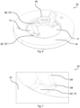
- schematically shows a perspective view on a rotor device according to the first embodiment;
- Fig. 3
- schematically shows a side view on the rotor device according to the first embodiment;
- Fig. 4
- schematically shows another side view on the rotor device according to the first embodiment;
- Fig. 5
- schematically shows a top view on the rotor device according to the first embodiment;
- Fig. 6
- schematically shows a perspective view on a rotor device according to a second embodiment of the invention;
- Fig. 7
- schematically shows an enlarged section of
Fig. 6 ; and - Fig. 8
- shows a rotor device according to prior art.
- In the Figures, like reference numerals designate like or functionally equivalent elements, unless otherwise indicated.
- A first embodiment of the invention is described, which is illustrated in
Figs. 1 to 5 . - A gas
hob control arrangement 20 for controlling a gas hob (not shown) has ashaft device 22, arotor device 24, aprotective cap 26, aspring device 32, avalve device 34, acase 36, and anelectronics device 28 having anignition switch device 30. Thecase 36 supports thevalve device 34 and theprotective cap 26, for example. - The
shaft device 22 defines a rotation axis A, that may also be referred to as central axis A. Indications like a radial direction or an axial direction refer to this rotation axis A, which also is a rotation axis of therotor device 24. - Preferably, the
shaft device 22 is integrally formed to be a single shaft. For torque transfer, theshaft device 22 may have achamfer 38. - The
rotor device 24 has acollar 40, in which anopening 42 is formed. Theopening 42 is a through hole that fits theshaft device 22 having thechamfer 38. For example, theopening 42 and theshaft device 22 form a tight fit. In other words, a cross section of theopening 42 is a negative of one cross section of theshaft device 22. Thecollar 40 forms a ring surrounding theshaft device 22. - The
collar 40 acts as a hub for theshaft device 22. In other words, thecollar 40 and theshaft device 22 form a shaft-hub-joint, by means of which a rotation and/or movement is transferable between theshaft device 22 and thecollar 40. - The
rotor device 24 has aring body 44. In a simple configuration, thering body 44 solely serves as an actuator or to-be-detected body for a detection function of theignition switch device 30. Thering body 44 preferably has a shape of a flat hollow cylinder. - An inner diameter D of the
ring body 44 is larger than a width W of theopening 42. The width W of theopening 42 corresponds to a diameter of theshaft device 22 at the location of thecollar 42. - The
rotor device 24 may serve further functions for theelectronics device 28, such as an entry device for entering a simmering level into an electronic valve control. - The
ring body 44 and thecollar 40 are axially offset to accommodate thelong spring device 32 between therotor device 24 and thevalve device 34. That is, thespring device 32 is interposed between thecollar 40 and thevalve device 34. Thus, therotor device 24 according to the invention can be arranged closer tovalve device 34, which results in the desired smaller gashob control arrangement 10. In alternative embodiments of the invention, thespring device 32 might be interposed between thecollar 40 and a part of thecase 36. - In the embodiments, the
spring device 32 is shown as a coil spring, which is the preferred type ofspring device 32. However, in alternative embodiments, thespring device 32 might be of a different type, such as an elastomer tube and/or one or more disc springs. - The
spring device 32 abuts afront face 46 of thecollar 40. Thefront face 46 is oriented axially towards thevalve device 34 and/or thering body 44. - The
collar 40 and thering body 44 are connected by twoarms 48. In alternative embodiments, there might be one, three ormore arms 48. Preferably, thearms 48 are symmetrically arranged around the rotation axis A, wherein symmetrically preferably means that a (virtual) axial displacement of thering body 44 relative to thecollar 40 keeps an alignment between thering body 44 and thecollar 40. It is even more preferred to have thearms 48 evenly, equidistantly and/or equiangularly arranged. - Circumferentially between the
arms 48 are drainage passages P. These drainage passages P ensure a desired drainage behavior. - Each of the
arms 48 has three arm sections: aninner arm section 50, acentral arm section 52, and anouter arm section 54. Preferably, the threearm sections inner arm section 50 and thecentral arm section 52 are preferably connected by a first joint 56. Theouter arm section 54 and thecentral arm section 52 are preferably connected by a second joint 58. Thejoints respective arm sections - The
inner arm section 50 protrudes radially outwards from thecollar 40. That is, thecollar 40 forms a radially inner end of theinner arm section 50, and the first joint 56 forms a radially outer end of theinner arm section 50. - Additionally, the
inner arm section 50 is optionally inclined. In other word, theinner arm section 50 extends radially and axially at the same time. Preferably, theinner arm section 50 extends away from thering body 44 as it extends from thecollar 40 to the first joint 56. - The
outer arm section 54 protrudes radially inwards from an innerperipheral surface 60 of thering body 44. That is, thering body 44 forms a radially outer end of theouter arm section 54, and the second joint 58 forms a radially inner end of theouter arm section 54. - The
central arm section 52 connects bothjoints central arm section 52 extends between the radially inner end of theouter arm section 54 and the radially outer end of theinner arm section 50. As thesejoints central arm section 52 extends axially to bridge this offset. - In this embodiments, the
central arm section 52 is inclined. That is, it extends both radially and axially. In the case of the first embodiment, thecentral arm section 52 extends radially outwards while extending from the radially inner end of theouter arm section 54, being the second joint 58, to the radially outer end of theinner arm section 50, being the first joint 56. - A circle, which is concentric with the
central axis 22 of therotor device 24, and which is tangential to the innermost edge and/or surface of theouter arm section 54, has a radius R. The radius R is larger than an outer diameter of theshaft device 22 to provide a radial gap for thespring device 32. The width W of theopening 42 usually corresponds to the diameter of theshaft device 22. Thus, it is preferred if the radius R is larger than half the width W. - The
rotor device 24 defines a hollow-cylindrical space 62, which is an installation space for thespring device 22. The hollow-cylindrical space 62 is designed into therotor device 24. In other words, the hollow-cylindrical space 62 is a virtual space that is present in the empty space between thecollar 40,ring body 44 andarms 48. The hollow-cylindrical space 62 is radially outside of a projection of theopening 42, that is projected parallel to thecentral axis 22. The hollow-cylindrical space 62 is radially inside inner faces and/or edges of thearms 48. In the embodiments, the hollow-cylindrical space 62 is radially inside an inner face of thesecond joints 58. The hollow-cylindrical space 62 extends axially between thefront face 46 of thecollar 40 facing towards thering body 44 and afront face 76 of thering body 44 facing away from thecollar 40. - In the gas
hob control arrangement 20, the hollow-cylindrical space 62 is radially outside of theshaft device 22. - The
arms 48 of the embodiments may have inclined arm sections for increased flexibility to be self-balancing. Thus, a potential misalignment of theshaft device 22 to theelectronics device 28 can be auto-compensated. - In this embodiment, the
central arm section 52 is inclined outwards. That is, thecentral arm section 52 extends radially outwards while extending axially from the radialinner end 58 of theouter arm section 54 to the radialouter end 56 of theinner arm section 50. - When mounted, the
inner arm section 50 is inclined upwards. That is, theinner arm section 50 extends axially away from thering body 44 while extending radially outwards from thecollar 40 to the radialouter end 56 of theinner arm section 50. Since theinner arm section 50 is inclined, all liquids that may land on theinner arm section 50 run down towards thecollar 40. At this point, chamfers from both sides of theinner arm section 50 meet in the middle, such that liquids do not rest upon theinner arm section 50. That is, theinner arm section 50 has a declinedtop surface 72 to improve drainage. - The
protective cap 26 has acylindrical section 64, which defines a through hoe 74 to encompass thearms 48 and/or thecollar 40. At one end of thecylindrical section 64, there is aring section 66. In thering section 66 there is a ring-shapedrecess 68. Theelectronics device 28 is accommodated in therecess 68. - The
recess 68 houses theelectronics device 28 radially inside, radially outside, and at one axial side. That is, therecess 68 is open at the other axial side. Thering body 24 is axially movable between an idle position and an activated position. In the idle position, thering body 24 is located adjacent to the open side of therecess 68. Thus, thering body 24 is arranged adjacent to theelectronics device 28, when thering body 24 is in the idle position. The idle position is depicted inFig. 1 . Theignition switch device 30, which is connected to the electronics deice 28, detects thering body 24, when thering body 24 is in the idle position. - Preferably, there is a handle (not shown) affixed to an upper end of the
shaft device 22 inFig. 1 . When a user presses the handle towards thevalve device 34, thering body 24 is moved from the idle position towards the activated position. When theignition switch device 30 detects that thering body 24 is not in the idle position and/or is in the activated position, theignition switch device 30 supplies an electric signal to an ignition device (not shown) to ignite a gas flowing from a burner. When the user releases a pressure on the handle, thespring device 32 pushes therotor device 24 back into the idle position. - The
spring device 32 preferably is configured to exert a preload onto thecollar 40, when therotor device 24 is in the idle position. That configuration ensures that thering body 24 is reliably positioned in the idle device. - When a user rotates the handle to adjust a gas flow from the
valve device 34, thering body 44 rotates around therotation axis 22. As thering body 44 is symmetrical to therotation axis 22, theignition switch device 30 is operatable by thering body 44 at every angular position. - As can be appreciated best from the side view of
Fig. 4 and the top view ofFig. 5 , thecentral arm section 52 and theinner arm section 50 have a varying section width B. As to theinner arm section 50, its section width B decreased linearly from the first joint 56 to thecollar 40. As to thecentral arm section 48, its section width B decreases linearly from the first joint 56 to the second joint 58. This variation in section width B provides a variation in bending strength, which increases a flexibility of thearms 48 without weakening thejoints - Next, a second embodiment of the invention is described with respect to
Figs. 6 and 7 . Therotor device 24 of the second embodiment corresponds to therotor device 24 of the first embodiment except for a shape of theouter arm sections 54. Thus, reference is made to the description of the first embodiment in all other regards. - The
outer arm sections 54 of the first embodiment have a rectangular cross section when cut tangentially. Thus, they have an increased strength but also a flat top surface 70 on which liquids may rest upon without completely draining. SeeFig. 2 for example. - The
outer arm sections 54 of the second embodiment have a nearly triangular cross section, when cut tangentially. The triangular cross section is an example for a prism-shaped cross section. Thus, theouter arm sections 54 according to the second embodiment have declined top surfaces 72. Due thereto, any liquid runs down from theouter arm sections 54, which is why a drainage behavior is improved. - Although the present invention has been described in accordance with preferred embodiments, it is obvious for the person skilled in the art that modifications are possible in all embodiments.
-
- A
- rotation axis / central axis
- B
- section width
- D
- inner diameter
- P
- drainage passage
- R
- radius
- W
- width
- 10
- rotor device
- 12
- hub
- 14
- ring body
- 16
- beam
- 18
- drainage passage
- 20
- gas hob control arrangement
- 22
- shaft device
- 24
- rotor device
- 26
- protective cap
- 28
- electronics device
- 30
- ignition switch device
- 32
- spring device
- 34
- valve device
- 36
- case
- 38
- chamfer
- 40
- collar
- 42
- opening
- 44
- ring body
- 46
- front face of collar
- 48
- arm
- 50
- inner arm section
- 52
- central arm section
- 54
- outer arm section
- 56
- first joint
- 58
- second joint
- 60
- inner peripheral surface of the ring body
- 62
- hollow-cylindrical space
- 64
- cylindrical section
- 66
- ring section
- 68
- recess
- 70
- flat top surface
- 72
- declined top surface
- 74
- through hole
- 76
- front face of ring body
Claims (10)
- A rotor device (24) for a gas hob control arrangement (20), comprising:a collar (40), that forms an opening (42) and is configured to transfer a rotating and/or translating movement between the rotor device (24) and a shaft device (22) receivable in the opening (42),a ring body (44), that has a larger inner diameter (D) than a width (W) of the opening (42), andat least one arm (48) comprising:an outer arm section (54), which extends radially inwards from the ring body (44),an inner arm section (50), which extends radially outwards from the collar (40), anda central arm section (52), which extends axially from a radially inner end (58) of the outer arm section (54) to a radially outer end (56) of the inner arm section (50).
- The rotor device (24) according to claim 1, wherein, when the collar (40) is positioned above the ring body (44) in a mounted position, at least one arm section (50, 52, 54) has a declined top surface (72).
- The rotor device (24) according to any preceding claim, wherein a radius (R) from a rotation axis (A) of the rotor device (24) to an inner end of the outer arm section (54) or to every inner end of the outer arm sections (54) is larger than half the width (W) of the opening (42).
- The rotor device (24) according to any preceding claim, comprising a hollow-cylindrical space (62) in an empty space, that is defined by an axially parallel projection of the opening (42) in the collar (40), inner faces and/or edges of the arm sections (50, 52, 54), a front face (46) of the collar (40) facing towards the ring body (44), and a front face (76) of the ring body (44) facing away from the collar (40).
- The rotor device (24) according to any preceding claim, wherein the central arm section (52) extends radially outwards while extending from the radially inner end (58) of the outer arm section (54) to a radially outer end (56) of the inner arm section (50).
- The rotor device (24) according to any preceding claim, wherein the inner arm section (50) is inclined such that it extends both radially outwards from the collar (40) and axially away from the ring body (44).
- The rotor device (24) according to any preceding claim, wherein the central arm section (52) is inclined such that it extends radially outwards while it extends axially away from the ring body (44) .
- A gas hob control arrangement (20) for controlling a gas hob, comprising:a shaft device (22) defining a rotation axis (A),a rotor device (24) according to any preceding claim, wherein the opening (42) of the collar (40) receives the shaft device (22) to be rotatable around the rotation axis (A) by a rotation of the shaft device (22), and wherein the rotor device (24) is movable along the rotation axis (A) between an idle position and a deflected position of the ring body (44), anda spring device (32), that is arranged radially between the shaft device (22) and the outer arm section (54) or outer arm sections (54) of the rotor device (24), and that preloads the rotor device (24) from the deflected position towards the idle position, andan ignition switch device (30), that is configured to supply electricity to an ignition device in a state where the ring body (44) is in the deflected position.
- The gas hob control arrangement (20) according to claim 8, further comprising a valve device (34), that is configured to be actuated by a rotation of the shaft device (22) to open or close a gas passage.
- The gas hob control arrangement (20) according to claims 8 or 9, further comprisinga protective cap (26), that has a through hole (74) and a recess (68), andan electronics device (28), that is housed in the recess (68),wherein the collar (40) and/or the at least one arm (48) reaches into the through hole (74) at least when the ring body (44) is in the idle position,wherein the recess (68) opens towards the ring body (44), andwherein the ring body (44) is adjacent to the electronics device (28) when the ring body (44) is in the idle position.
Applications Claiming Priority (1)
| Application Number | Priority Date | Filing Date | Title |
|---|---|---|---|
| EP23382057 | 2023-01-24 |
Publications (2)
| Publication Number | Publication Date |
|---|---|
| EP4407236A1 true EP4407236A1 (en) | 2024-07-31 |
| EP4407236B1 EP4407236B1 (en) | 2025-08-06 |
Family
ID=85076109
Family Applications (1)
| Application Number | Title | Priority Date | Filing Date |
|---|---|---|---|
| EP24151001.5A Active EP4407236B1 (en) | 2023-01-24 | 2024-01-09 | Rotor for gas hob control |
Country Status (1)
| Country | Link |
|---|---|
| EP (1) | EP4407236B1 (en) |
Cited By (1)
| Publication number | Priority date | Publication date | Assignee | Title |
|---|---|---|---|---|
| US20240393820A1 (en) * | 2021-08-20 | 2024-11-28 | Samsung Electronics Co., Ltd. | Knob assembly and electronic device comprising same |
Citations (6)
| Publication number | Priority date | Publication date | Assignee | Title |
|---|---|---|---|---|
| GB2130438A (en) * | 1982-11-10 | 1984-05-31 | Bosch Siemens Hausgeraete | Rotary knob |
| US7285738B2 (en) * | 2006-02-15 | 2007-10-23 | Whirlpool Corporation | Control knob and control panel |
| EP2383519A2 (en) * | 2010-04-28 | 2011-11-02 | BSH Bosch und Siemens Hausgeräte GmbH | Gas valve with ignition device |
| CN104566518A (en) * | 2013-10-29 | 2015-04-29 | 樱花卫厨(中国)股份有限公司 | Waterproof seal ring of switch of gas stove |
| WO2017161405A1 (en) * | 2016-03-24 | 2017-09-28 | Electrolux Home Products Pty Limited | Gas knob skirt retainer |
| WO2021228830A1 (en) * | 2020-05-13 | 2021-11-18 | BSH Hausgeräte GmbH | Gas stove |
-
2024
- 2024-01-09 EP EP24151001.5A patent/EP4407236B1/en active Active
Patent Citations (6)
| Publication number | Priority date | Publication date | Assignee | Title |
|---|---|---|---|---|
| GB2130438A (en) * | 1982-11-10 | 1984-05-31 | Bosch Siemens Hausgeraete | Rotary knob |
| US7285738B2 (en) * | 2006-02-15 | 2007-10-23 | Whirlpool Corporation | Control knob and control panel |
| EP2383519A2 (en) * | 2010-04-28 | 2011-11-02 | BSH Bosch und Siemens Hausgeräte GmbH | Gas valve with ignition device |
| CN104566518A (en) * | 2013-10-29 | 2015-04-29 | 樱花卫厨(中国)股份有限公司 | Waterproof seal ring of switch of gas stove |
| WO2017161405A1 (en) * | 2016-03-24 | 2017-09-28 | Electrolux Home Products Pty Limited | Gas knob skirt retainer |
| WO2021228830A1 (en) * | 2020-05-13 | 2021-11-18 | BSH Hausgeräte GmbH | Gas stove |
Cited By (1)
| Publication number | Priority date | Publication date | Assignee | Title |
|---|---|---|---|---|
| US20240393820A1 (en) * | 2021-08-20 | 2024-11-28 | Samsung Electronics Co., Ltd. | Knob assembly and electronic device comprising same |
Also Published As
| Publication number | Publication date |
|---|---|
| EP4407236B1 (en) | 2025-08-06 |
Similar Documents
| Publication | Publication Date | Title |
|---|---|---|
| EP4407236B1 (en) | Rotor for gas hob control | |
| US8038155B2 (en) | Magnetically-controlled rotary seal | |
| US6834863B2 (en) | Ball joint seal | |
| US7757570B1 (en) | Torque sensor with alignment system | |
| KR940004725B1 (en) | Thrust bearing assembly | |
| US4339737A (en) | Rotary electrically actuated device | |
| SE432992B (en) | MANOVER AND CONTROL DEVICE FOR A VALVE WITH A DOOM-SIZED METAL MEMBRANE | |
| KR20020072203A (en) | Torsion vibration damper | |
| AU2002329852A1 (en) | Pressure regulator | |
| US20030117037A1 (en) | Linear or rotary actuator | |
| US12224651B2 (en) | Electric motor having a fan guard and rotor shaft mounted rotatably relative to the fan guard and angle sensor | |
| CA2325464A1 (en) | Adjustable tube-cleaner device | |
| US12523307B2 (en) | Valve device having a hold-down element | |
| KR102573052B1 (en) | Motor Sensor Magnet Assembly Structure | |
| US4482291A (en) | Automatic air inlet damper | |
| US5051693A (en) | Bearing seat encoder mount for rotational parameter sensor apparatus | |
| US20140000408A1 (en) | Accelerator apparatus for vehicle | |
| US20100201077A1 (en) | Sealing Ring | |
| US5775737A (en) | Conduit vibration decoupling device | |
| SE447670B (en) | COB BUSH WITH RECYCLING COULD | |
| SE466770B (en) | VALVE WITH SPRING INSTALLED SEATING RING | |
| JP2000193120A (en) | solenoid valve | |
| US20040124044A1 (en) | Compact braked rolling bearing | |
| AU648461B2 (en) | Electromagnetic rotating actuator | |
| KR970027880A (en) | Coupling Spring Element |
Legal Events
| Date | Code | Title | Description |
|---|---|---|---|
| PUAI | Public reference made under article 153(3) epc to a published international application that has entered the european phase |
Free format text: ORIGINAL CODE: 0009012 |
|
| STAA | Information on the status of an ep patent application or granted ep patent |
Free format text: STATUS: THE APPLICATION HAS BEEN PUBLISHED |
|
| AK | Designated contracting states |
Kind code of ref document: A1 Designated state(s): AL AT BE BG CH CY CZ DE DK EE ES FI FR GB GR HR HU IE IS IT LI LT LU LV MC ME MK MT NL NO PL PT RO RS SE SI SK SM TR |
|
| STAA | Information on the status of an ep patent application or granted ep patent |
Free format text: STATUS: REQUEST FOR EXAMINATION WAS MADE |
|
| 17P | Request for examination filed |
Effective date: 20250131 |
|
| GRAP | Despatch of communication of intention to grant a patent |
Free format text: ORIGINAL CODE: EPIDOSNIGR1 |
|
| STAA | Information on the status of an ep patent application or granted ep patent |
Free format text: STATUS: GRANT OF PATENT IS INTENDED |
|
| RIC1 | Information provided on ipc code assigned before grant |
Ipc: H01H 3/16 20060101ALN20250212BHEP Ipc: F16K 37/00 20060101ALI20250212BHEP Ipc: G05G 1/12 20060101ALI20250212BHEP Ipc: F16K 3/08 20060101ALI20250212BHEP Ipc: H01H 3/10 20060101ALI20250212BHEP Ipc: F24C 3/12 20060101AFI20250212BHEP |
|
| INTG | Intention to grant announced |
Effective date: 20250318 |
|
| GRAS | Grant fee paid |
Free format text: ORIGINAL CODE: EPIDOSNIGR3 |
|
| GRAA | (expected) grant |
Free format text: ORIGINAL CODE: 0009210 |
|
| STAA | Information on the status of an ep patent application or granted ep patent |
Free format text: STATUS: THE PATENT HAS BEEN GRANTED |
|
| AK | Designated contracting states |
Kind code of ref document: B1 Designated state(s): AL AT BE BG CH CY CZ DE DK EE ES FI FR GB GR HR HU IE IS IT LI LT LU LV MC ME MK MT NL NO PL PT RO RS SE SI SK SM TR |
|
| REG | Reference to a national code |
Ref country code: GB Ref legal event code: FG4D |
|
| REG | Reference to a national code |
Ref country code: CH Ref legal event code: EP |
|
| REG | Reference to a national code |
Ref country code: DE Ref legal event code: R096 Ref document number: 602024000373 Country of ref document: DE |
|
| REG | Reference to a national code |
Ref country code: IE Ref legal event code: FG4D |
|
| REG | Reference to a national code |
Ref country code: NL Ref legal event code: MP Effective date: 20250806 |
|
| PG25 | Lapsed in a contracting state [announced via postgrant information from national office to epo] |
Ref country code: IS Free format text: LAPSE BECAUSE OF FAILURE TO SUBMIT A TRANSLATION OF THE DESCRIPTION OR TO PAY THE FEE WITHIN THE PRESCRIBED TIME-LIMIT Effective date: 20251206 |
|
| PG25 | Lapsed in a contracting state [announced via postgrant information from national office to epo] |
Ref country code: NO Free format text: LAPSE BECAUSE OF FAILURE TO SUBMIT A TRANSLATION OF THE DESCRIPTION OR TO PAY THE FEE WITHIN THE PRESCRIBED TIME-LIMIT Effective date: 20251106 |
|
| REG | Reference to a national code |
Ref country code: LT Ref legal event code: MG9D |
|
| PG25 | Lapsed in a contracting state [announced via postgrant information from national office to epo] |
Ref country code: PT Free format text: LAPSE BECAUSE OF FAILURE TO SUBMIT A TRANSLATION OF THE DESCRIPTION OR TO PAY THE FEE WITHIN THE PRESCRIBED TIME-LIMIT Effective date: 20251209 |
|
| PG25 | Lapsed in a contracting state [announced via postgrant information from national office to epo] |
Ref country code: FI Free format text: LAPSE BECAUSE OF FAILURE TO SUBMIT A TRANSLATION OF THE DESCRIPTION OR TO PAY THE FEE WITHIN THE PRESCRIBED TIME-LIMIT Effective date: 20250806 |
|
| PG25 | Lapsed in a contracting state [announced via postgrant information from national office to epo] |
Ref country code: HR Free format text: LAPSE BECAUSE OF FAILURE TO SUBMIT A TRANSLATION OF THE DESCRIPTION OR TO PAY THE FEE WITHIN THE PRESCRIBED TIME-LIMIT Effective date: 20250806 Ref country code: NL Free format text: LAPSE BECAUSE OF FAILURE TO SUBMIT A TRANSLATION OF THE DESCRIPTION OR TO PAY THE FEE WITHIN THE PRESCRIBED TIME-LIMIT Effective date: 20250806 |
|
| PG25 | Lapsed in a contracting state [announced via postgrant information from national office to epo] |
Ref country code: GR Free format text: LAPSE BECAUSE OF FAILURE TO SUBMIT A TRANSLATION OF THE DESCRIPTION OR TO PAY THE FEE WITHIN THE PRESCRIBED TIME-LIMIT Effective date: 20251107 |
|
| PG25 | Lapsed in a contracting state [announced via postgrant information from national office to epo] |
Ref country code: SE Free format text: LAPSE BECAUSE OF FAILURE TO SUBMIT A TRANSLATION OF THE DESCRIPTION OR TO PAY THE FEE WITHIN THE PRESCRIBED TIME-LIMIT Effective date: 20250806 |
|
| PG25 | Lapsed in a contracting state [announced via postgrant information from national office to epo] |
Ref country code: LV Free format text: LAPSE BECAUSE OF FAILURE TO SUBMIT A TRANSLATION OF THE DESCRIPTION OR TO PAY THE FEE WITHIN THE PRESCRIBED TIME-LIMIT Effective date: 20250806 |
|
| PG25 | Lapsed in a contracting state [announced via postgrant information from national office to epo] |
Ref country code: BG Free format text: LAPSE BECAUSE OF FAILURE TO SUBMIT A TRANSLATION OF THE DESCRIPTION OR TO PAY THE FEE WITHIN THE PRESCRIBED TIME-LIMIT Effective date: 20250806 Ref country code: PL Free format text: LAPSE BECAUSE OF FAILURE TO SUBMIT A TRANSLATION OF THE DESCRIPTION OR TO PAY THE FEE WITHIN THE PRESCRIBED TIME-LIMIT Effective date: 20250806 |
|
| PG25 | Lapsed in a contracting state [announced via postgrant information from national office to epo] |
Ref country code: RS Free format text: LAPSE BECAUSE OF FAILURE TO SUBMIT A TRANSLATION OF THE DESCRIPTION OR TO PAY THE FEE WITHIN THE PRESCRIBED TIME-LIMIT Effective date: 20251106 |
|
| PG25 | Lapsed in a contracting state [announced via postgrant information from national office to epo] |
Ref country code: ES Free format text: LAPSE BECAUSE OF FAILURE TO SUBMIT A TRANSLATION OF THE DESCRIPTION OR TO PAY THE FEE WITHIN THE PRESCRIBED TIME-LIMIT Effective date: 20250806 |
|
| REG | Reference to a national code |
Ref country code: AT Ref legal event code: MK05 Ref document number: 1822233 Country of ref document: AT Kind code of ref document: T Effective date: 20250806 |
|
| PG25 | Lapsed in a contracting state [announced via postgrant information from national office to epo] |
Ref country code: SM Free format text: LAPSE BECAUSE OF FAILURE TO SUBMIT A TRANSLATION OF THE DESCRIPTION OR TO PAY THE FEE WITHIN THE PRESCRIBED TIME-LIMIT Effective date: 20250806 |
|
| PG25 | Lapsed in a contracting state [announced via postgrant information from national office to epo] |
Ref country code: DK Free format text: LAPSE BECAUSE OF FAILURE TO SUBMIT A TRANSLATION OF THE DESCRIPTION OR TO PAY THE FEE WITHIN THE PRESCRIBED TIME-LIMIT Effective date: 20250806 |
|
| PG25 | Lapsed in a contracting state [announced via postgrant information from national office to epo] |
Ref country code: AT Free format text: LAPSE BECAUSE OF FAILURE TO SUBMIT A TRANSLATION OF THE DESCRIPTION OR TO PAY THE FEE WITHIN THE PRESCRIBED TIME-LIMIT Effective date: 20250806 |
|
| PGFP | Annual fee paid to national office [announced via postgrant information from national office to epo] |
Ref country code: IT Payment date: 20260131 Year of fee payment: 3 |
|
| PGFP | Annual fee paid to national office [announced via postgrant information from national office to epo] |
Ref country code: TR Payment date: 20260108 Year of fee payment: 3 |
|
| PG25 | Lapsed in a contracting state [announced via postgrant information from national office to epo] |
Ref country code: CZ Free format text: LAPSE BECAUSE OF FAILURE TO SUBMIT A TRANSLATION OF THE DESCRIPTION OR TO PAY THE FEE WITHIN THE PRESCRIBED TIME-LIMIT Effective date: 20250806 |
|
| PG25 | Lapsed in a contracting state [announced via postgrant information from national office to epo] |
Ref country code: EE Free format text: LAPSE BECAUSE OF FAILURE TO SUBMIT A TRANSLATION OF THE DESCRIPTION OR TO PAY THE FEE WITHIN THE PRESCRIBED TIME-LIMIT Effective date: 20250806 Ref country code: SK Free format text: LAPSE BECAUSE OF FAILURE TO SUBMIT A TRANSLATION OF THE DESCRIPTION OR TO PAY THE FEE WITHIN THE PRESCRIBED TIME-LIMIT Effective date: 20250806 |