EP4407223A1 - Gas distribution system for aircrafts - Google Patents
Gas distribution system for aircrafts Download PDFInfo
- Publication number
- EP4407223A1 EP4407223A1 EP23152996.7A EP23152996A EP4407223A1 EP 4407223 A1 EP4407223 A1 EP 4407223A1 EP 23152996 A EP23152996 A EP 23152996A EP 4407223 A1 EP4407223 A1 EP 4407223A1
- Authority
- EP
- European Patent Office
- Prior art keywords
- distribution system
- gas distribution
- hydrogen
- corrugated hose
- gas
- Prior art date
- Legal status (The legal status is an assumption and is not a legal conclusion. Google has not performed a legal analysis and makes no representation as to the accuracy of the status listed.)
- Granted
Links
Images

Classifications
-
- F—MECHANICAL ENGINEERING; LIGHTING; HEATING; WEAPONS; BLASTING
- F17—STORING OR DISTRIBUTING GASES OR LIQUIDS
- F17D—PIPE-LINE SYSTEMS; PIPE-LINES
- F17D1/00—Pipe-line systems
- F17D1/02—Pipe-line systems for gases or vapours
- F17D1/04—Pipe-line systems for gases or vapours for distribution of gas
-
- B—PERFORMING OPERATIONS; TRANSPORTING
- B64—AIRCRAFT; AVIATION; COSMONAUTICS
- B64D—EQUIPMENT FOR FITTING IN OR TO AIRCRAFT; FLIGHT SUITS; PARACHUTES; ARRANGEMENT OR MOUNTING OF POWER PLANTS OR PROPULSION TRANSMISSIONS IN AIRCRAFT
- B64D37/00—Arrangements in connection with fuel supply for power plant
- B64D37/005—Accessories not provided for in the groups B64D37/02 - B64D37/28
-
- B—PERFORMING OPERATIONS; TRANSPORTING
- B64—AIRCRAFT; AVIATION; COSMONAUTICS
- B64D—EQUIPMENT FOR FITTING IN OR TO AIRCRAFT; FLIGHT SUITS; PARACHUTES; ARRANGEMENT OR MOUNTING OF POWER PLANTS OR PROPULSION TRANSMISSIONS IN AIRCRAFT
- B64D37/00—Arrangements in connection with fuel supply for power plant
- B64D37/30—Fuel systems for specific fuels
-
- B—PERFORMING OPERATIONS; TRANSPORTING
- B64—AIRCRAFT; AVIATION; COSMONAUTICS
- B64D—EQUIPMENT FOR FITTING IN OR TO AIRCRAFT; FLIGHT SUITS; PARACHUTES; ARRANGEMENT OR MOUNTING OF POWER PLANTS OR PROPULSION TRANSMISSIONS IN AIRCRAFT
- B64D37/00—Arrangements in connection with fuel supply for power plant
- B64D37/32—Safety measures not otherwise provided for, e.g. preventing explosive conditions
-
- F—MECHANICAL ENGINEERING; LIGHTING; HEATING; WEAPONS; BLASTING
- F16—ENGINEERING ELEMENTS AND UNITS; GENERAL MEASURES FOR PRODUCING AND MAINTAINING EFFECTIVE FUNCTIONING OF MACHINES OR INSTALLATIONS; THERMAL INSULATION IN GENERAL
- F16L—PIPES; JOINTS OR FITTINGS FOR PIPES; SUPPORTS FOR PIPES, CABLES OR PROTECTIVE TUBING; MEANS FOR THERMAL INSULATION IN GENERAL
- F16L11/00—Hoses, i.e. flexible pipes
- F16L11/04—Hoses, i.e. flexible pipes made of rubber or flexible plastics
- F16L11/11—Hoses, i.e. flexible pipes made of rubber or flexible plastics with corrugated wall
-
- F—MECHANICAL ENGINEERING; LIGHTING; HEATING; WEAPONS; BLASTING
- F16—ENGINEERING ELEMENTS AND UNITS; GENERAL MEASURES FOR PRODUCING AND MAINTAINING EFFECTIVE FUNCTIONING OF MACHINES OR INSTALLATIONS; THERMAL INSULATION IN GENERAL
- F16L—PIPES; JOINTS OR FITTINGS FOR PIPES; SUPPORTS FOR PIPES, CABLES OR PROTECTIVE TUBING; MEANS FOR THERMAL INSULATION IN GENERAL
- F16L11/00—Hoses, i.e. flexible pipes
- F16L11/14—Hoses, i.e. flexible pipes made of rigid material, e.g. metal or hard plastics
- F16L11/15—Hoses, i.e. flexible pipes made of rigid material, e.g. metal or hard plastics corrugated
-
- F—MECHANICAL ENGINEERING; LIGHTING; HEATING; WEAPONS; BLASTING
- F16—ENGINEERING ELEMENTS AND UNITS; GENERAL MEASURES FOR PRODUCING AND MAINTAINING EFFECTIVE FUNCTIONING OF MACHINES OR INSTALLATIONS; THERMAL INSULATION IN GENERAL
- F16L—PIPES; JOINTS OR FITTINGS FOR PIPES; SUPPORTS FOR PIPES, CABLES OR PROTECTIVE TUBING; MEANS FOR THERMAL INSULATION IN GENERAL
- F16L51/00—Expansion-compensation arrangements for pipe-lines
- F16L51/02—Expansion-compensation arrangements for pipe-lines making use of a bellows or an expansible folded or corrugated tube
- F16L51/025—Expansion-compensation arrangements for pipe-lines making use of a bellows or an expansible folded or corrugated tube with several corrugations
- F16L51/027—Expansion-compensation arrangements for pipe-lines making use of a bellows or an expansible folded or corrugated tube with several corrugations with external reinforcement
Definitions
- the present disclosure relates to gas distribution systems in general, and in particular to Hydrogen distribution systems for aircrafts.
- Hydrogen (H 2 ) becomes increasingly important as an energy carrier.
- Hydrogen H 2
- aeronautic applications such as in aircrafts, the strict requirements are particularly hard to fulfill.
- the aircraft itself during flight is a highly dynamic environment which deforms, e.g., during flight maneuvers or in turbulent atmosphere. Since any Hydrogen system in the aircraft needs to be attached to the aircraft in some way, these deformations are propagated to the Hydrogen system, and in particular to any piping/distribution system for the Hydrogen. Therefore, for such piping/distribution systems (such as in general for every piping within an airplane) such deformations need to be considered.
- a gas distribution system for aircrafts comprises a corrugated hose having a first connecting end and a second connecting end, and a shroud.
- the shroud surrounds the corrugated hose concentrically along a longitudinal direction of the corrugated hose, thereby building an intermediate space between the corrugated hose and the shroud.
- the first connecting end is configured to be connected to a gas tank.
- the second connecting end is configured to be connected to a gas consumer.
- the corrugated house is flexible so as to compensate for in-flight deflections of the gas distribution system.
- the gas distribution system functionally corresponds to a "piping system" for gaseous fuel.
- the corrugated hose is an elongated tube-like element that builds a conducting space for a fluid, such as gaseous fuel (e.g., gaseous Hydrogen).
- the corrugated hose may be a flexible cylindrical hollow element extending in a generally longitudinal direction and having corrugates or ripples/grooves that each extend in a circumferential direction of the corrugated hose, i.e., perpendicular to the longitudinal direction. Therefore, in a cross-section along the longitudinal direction, the corrugates build a wave-like pattern.
- the corrugated hose is flexible in that sense, that it may compensate for deflections within the aircraft, i.e., yield to mechanical loads inserted into the corrugated hose.
- the corrugations allow for the corrugated hose to deform appropriately in response to mechanical loads acting onto the hose, such that the loads are compensated.
- a cross-section of the corrugated hose perpendicular to the longitudinal direction may also have shapes other than cylindrical, such as rectangular, square, or any other suitable shape.
- the corrugated hose may, in general, comprise or consist of a gas-tight material.
- the corrugated hose may, in particular, comprise or consist of a material exhibiting a very low permeation for Hydrogen, such that diffusion of Hydrogen through the corrugated hose is reduced.
- the corrugated hose may optionally comprise an inner liner, i.e., an additional flat but flexible layer (such as, for example, a foil).
- an inner liner may flatten the inner surface of the corrugated hose to avoid or reduce pressure losses and/or flow losses caused by turbulences that may otherwise occur at the corrugations of the corrugated hose when the fluid (e.g., Hydrogen) passes by.
- the first connecting end and the second connecting end both correspond to openings at opposite sides in the "tube" defined by the corrugated hose and act as inlet and outlet openings of the gas conducted/distributed by the gas distribution system, respectively.
- the first connecting end may, for example, be connected to an outlet of a gas tank.
- the second connecting end may be connected to an inlet of a gas consumer, for example (in the case of a Hydrogen distribution system) a Hydrogen consumer such as a corresponding turbine or any other consumer. Therefore, when mounted into a gas fuel system, the corrugated hose of the gas distribution system directs the gas from the gas tank to the gas consumer.
- the corrugated hose may also consist of multiple single corrugated hose elements that are added together.
- a first corrugated hose element and a second corrugated hose element may be added together and sealed, such that the two corrugated hose elements together build the corrugated hose.
- the shroud also consists of corresponding single shroud elements surrounding the corresponding corrugated hose element.
- the second end of the first corrugated hose element is connected to the first end of the second corrugated hose element.
- the first end of the first corrugated hose element may then be connected to the gas tank and the second end of the second corrugated hose element may be connected to the gas consumer.
- such a single corrugated hose element may have a branch or splitting point, such that, for example, two or more additional corrugated hose elements (and with it shroud elements) are connected to one end of the first corrugated hose element, thereby building a network of a gas distribution system comprising multiple corrugated hoses and corresponding shrouds.
- a branch or splitting point such that, for example, two or more additional corrugated hose elements (and with it shroud elements) are connected to one end of the first corrugated hose element, thereby building a network of a gas distribution system comprising multiple corrugated hoses and corresponding shrouds.
- Each of the single gas distribution systems built in this way by the single corrugated hoses and shrouds may be configured according to any one of the embodiments described herein.
- the corrugated hose is flexible in the above manner, a single continuous (uninterrupted) hose between the gas tank and the gas consumer may be used. This avoids additional sealings within single segments, such as necessary in regular piping systems, and therefore avoids potentially additional leakage points at such sealings.
- the disclosed gas distribution system only needs sealings at the endings of the corrugated hose and shroud.
- the shroud surrounds the corrugated hose in a cladding-like manner concentrically and also extends in the longitudinal direction, in order to protect the corrugated hose and to establish the necessary mechanical stiffness.
- the shroud itself is non-flexible.
- the shroud and the corrugated hose together build an intermediate space between them in a radial direction, which may, for example (as described further below) be filled with a quenching medium, to decrease fire or explosion hazards.
- the shroud is configured to be connected to a gas tank and a gas consumer on its respective ends. However, the shroud does not conduct the fuel gas. To build a sealed intermediate space, the ends of the shroud are sealed against the gas tank and the gas consumer, e.g., by means of conventional sealings.
- the gas distribution system further comprises a plurality of spacers in the intermediate space, keeping the corrugated hose and the shroud at a radial distance to each other and thereby avoiding chafing between the corrugated hose and the shroud.
- the spacers are spaced apart from each other along the longitudinal direction.
- Such spacers may, for example, be regular plastic spacers or other suitable spacers for holding the shroud at a defined radial distance to the corrugated hose.
- the gas distribution system further comprises at least one bellows connecting a first portion of the shroud with a second portion of the shroud, so that the first portion and the second portion are moveable with regard to each other.
- the at least one bellows may, for example, be a steel bellows which also has a wave-like cross-section in the longitudinal direction.
- the corrugated hose extends through the bellows without contacting it.
- the bellows itself is connected to the first portion and the second portion of the shroud and interconnects these portions with each other.
- the bellows defines a first section of the shroud and a second section of the shroud an connects these section with each other. Since the shroud itself, or rather the first portion and the second portion of the shroud are made from a stiff material (to provide the necessary mechanical overall stiffness), it is necessary to provide the shroud with compensation capabilities similar to those of the corrugated house.
- the bellows may compensate for deflections (e.g., by slight deformations), while the shroud itself is stiff and mechanically supports the whole structure of the gas distribution system on a large scale.
- the bellows may be made from a gas tight (in particular embodiments especially hydrogen-tight) material providing low permeation of the gas.
- the bellows may be made from steel.
- the intermediate space is filled with a quenching medium.
- Such a quenching medium separates the gas inside the corrugated hose from the surrounding air, and therefore from the Oxygen contained therein.
- the gas inside the corrugated hose in particular Hydrogen in certain embodiments
- the quenching medium itself is an inert (chemically non-reactive) medium, which helps suppress building of dangerous gas mixtures of the gas with the surrounding Oxygen (if the gas inside the corrugated hose is Hydrogen, in particular the formation of Oxyhydrogen gas is avoided).
- the quenching medium is a quenching gas.
- Such a quenching gas may be any suitable inert gas, such as Nitrogen, Helium, Argon, Xenon, that helps to prevent formation of dangerous gas mixtures.
- the quenching gas is Nitrogen.
- Nitrogen is an inert gas that is suitable to avoid formation of Oxyhydrogen by avoiding contact between the gas conducted in the corrugated hose and the surrounding Oxygen.
- the shroud comprises at least two flushing openings for flushing the intermediate space and/or filling the intermediate space with a quenching medium.
- the flushing openings may be used to initially fill the intermediate space with the quenching medium after the gas distribution system has been installed between the gas tank and the gas consumer.
- a first flushing opening may be present at one end of the shroud and a second flushing opening may be present at the other end of the shroud.
- the flushing openings are penetrating the shroud but do not penetrate the corrugated hose, such that the flushing openings are openings into the intermediate space from the outside of the gas distribution system.
- new quenching medium may be pumped into one of the flushing openings and the old quenching medium may be removed through the other flushing opening, for example by means of a corresponding pump that can be connected to the flushing opening.
- the flushing opening may be closed and sealed with corresponding seals.
- the gas distribution system is a distribution system for gaseous Hydrogen.
- the corrugated hose comprises a material having a low permeability for Hydrogen.
- the corrugated hose comprises steel.
- Steel provides for a low permeation/diffusion of Hydrogen molecules and therefore is a preferred material for the corrugated hose and for the shroud.
- other low diffusion materials are conceivable, too.
- steel is easy to weld and can be tested for Hydrogen-tightness.
- steel by nature is electrically conductive and therefore decreases the probability of electrostatic discharges that might ignite Oxyhydrogen gas that might be present because it is in general not possible to have an absolutely Hydrogen-tight system. Therefore, using steel for the corrugated hose (and the shroud) decrease the risk of ignition and therefore of fires or explosions.
- the shroud comprises steel.
- steel for the shroud is in particular advantageous because the bellows preferably is made from steel, too. This allows for the shroud and the bellows to be welded together. Further, using steel for the shroud improves fire protection and mechanical protection for the corrugated hose because of the high fire resistance and good mechanical stability.
- the corrugated hose comprises an elastomer.
- Such an elastomer also provides low diffusion of Hydrogen and may be conceivable, too, although steel is the preferred material.
- the materials of the corrugated hose and of the shroud each comprise a very low tendency for electrostatic discharge.
- Such materials e.g., steel, as described above) decrease the ignition risk.
- first connecting end and the second connecting end each comprise a gas-tight sealing.
- Such a gas-tight sealings may be a conventional gas-tight sealing, such as O-rings.
- a conventional gas-tight sealing such as O-rings.
- O-rings the full distance between the gas tank and the gas consumer is covered by the corrugated hose.
- Such conventional sealings can be used only at the connecting ends of the corrugated hose. Additional sealings connecting sections, such as in standard tubing systems, are avoided, thereby decreasing gas diffusion, and increasing gas-tightness of the gas distribution system.
- an aircraft comprising a fuselage, a Hydrogen consumer, a Hydrogen tank, and a gas distribution system (10) as described above.
- the gas distribution system fluidly connects the Hydrogen tank with the Hydrogen consumer, so that the Hydrogen consumer receives Hydrogen from the Hydrogen tank via the gas distribution system.
- the Hydrogen consumer may, for example, be a Hydrogen turbine, a fuel cell, or any other Hydrogen consumer.
- the gas distribution system conducts gaseous Hydrogen from the Hydrogen tank to the Hydrogen consumer.
- the gas distribution may be configured according to any one of the embodiments described above.
- the present disclosure provides a gas distribution system, that is in particular suitable for Hydrogen conduction between a Hydrogen tank and a Hydrogen consumer in aircrafts, but may be used for other gases, too.
- the configuration of a single corrugated hose and a shroud with at least one bellows surrounding the house and defining an intermediate space between the shroud and the corrugated hose provides a gas distribution system, that compensates for deflections, for example during flight maneuvers, but still provides the necessary overall stiffness.
- Providing a quenching medium, such as a Nitrogen gas, within the intermediate space further decreases explosion risks caused by dangerous Oxyhydrogen gas formed by Hydrogen diffusion.
- the used materials for the components in particular steel, further provide low electrostatic discharge probabilities, further enhancing fire and explosion protection.
- a bellows (preferably from steel) may further be used to compensate for deflections transferred via the shroud. Further, using steel for the bellows, too, adds to the fire protection and mechanical protection for the corrugated hose.
- FIGs. 1 and 2 show a gas distribution system 10 for Hydrogen for an aircraft 100.
- Fig. 1 shows a schematic isometric view of the gas distribution system 10.
- Fig. 2 shows a cut-view along a longitudinal direction 5 of the gas distribution system 10 of Fig. 1 .
- Figs. 1 and 2 will be described together.
- the gas distribution system 10 comprises a corrugated hose 1 (best seen in Fig. 2 ), a shroud 4 (best seen in Fig. 1 ) and a bellows 8.
- the shroud 4 comprises a first portion 20 and a second portion 30. The first portion 20 and the second portion 30 of the shroud 4 are connected by the bellows 8.
- the corrugated hose 1 extends along the full length of the gas distribution system 10.
- the corrugated hose 1 as a whole may also consist of single corrugated hose elements added together.
- the shroud 4 (first portion 20 of the shroud 4 and second portion 30 of the shroud 4) as well as the bellows 8 surround the corrugated hose 1 concentrically and along the longitudinal direction 5 of the gas distribution system 10. Spacers 6 hold the shroud 4 at a defined radial distance to the corrugated hose 1 and avoid chafing between the corrugated hose 1 and the shroud 4.
- the shroud 4 protects the corrugated hose 1 and establishes the necessary mechanical stiffness.
- the shroud 4 itself is non-flexible.
- the shroud 4 and the corrugated hose 1 together build an intermediate space 7 between them in a radial direction, which is (as described above and below) filled with a Nitrogen quenching gas, to decrease fire or explosion hazards.
- the shroud 4 is configured to be connected to a Hydrogen tank 130 (see Fig. 3 ) and a Hydrogen consumer 120 on its respective ends. However, the shroud 4 does not conduct the Hydrogen.
- To build a sealed intermediate space 7, the ends of the shroud 4 are sealed against the Hydrogen tank 130 ( Fig. 3 ) and the Hydrogen consumer 120 ( Fig. 3 ), e.g., by means of conventional sealings at flanges 12.
- the flanges 12 may, for example, be welded or bolted to the Hydrogen tank 130 and the Hydrogen consumer 120, respectively.
- the intermediate space 7 between the corrugated hose 1 and the shroud 4 is filled with a Nitrogen quenching gas (not shown).
- a Nitrogen quenching gas separates the Hydrogen inside the corrugated hose 1 from the surrounding air, and therefore from the Oxygen contained therein.
- the Hydrogen inside the corrugated hose 1 diffuses through the wall of the corrugated hose 1, the Hydrogen first enters the intermediate space 7 and is mixed and diluted with the Nitrogen quenching gas.
- the Nitrogen quenching gas itself is an inert (chemically non-reactive) gas, which helps suppress formation of dangerous gas mixtures of the Hydrogen with the surrounding Oxygen (i.e., the formation of Oxyhydrogen), which would be an explosion risk.
- a first connecting end 2 of the corrugated hose 1 is configured to be connected to a Hydrogen tank 130 (see Fig. 3 ).
- a second connecting end 3 of the corrugated hose 1 is configured to be connected to a Hydrogen consumer 120, such as a Hydrogen turbine (see Fig. 3 ). Therefore, the corrugated hose 1 conducts the Hydrogen gas from the Hydrogen tank 130 to the Hydrogen consumer 120.
- the corrugated hose 1 is an elongated tube-like element that builds a conducting space for a fluid, such as gaseous fuel (e.g., gaseous Hydrogen in the shown example).
- the corrugated hose 1 is a flexible cylindrical hollow element extending generally in the longitudinal direction 5 and having corrugates 9 or ripples/grooves 9 that each extend in a circumferential direction 11 of the corrugated hose 1, i.e., perpendicular to the longitudinal direction 5. Therefore, in a cross-section along the longitudinal direction (shown in Fig. 2 ), the corrugates 9 build a wave-like pattern.
- the corrugated hose 1 is flexible in that sense, that it may compensate for deflections within the aircraft, i.e., yield to mechanical loads inserted into the corrugated hose 1 by slightly deforming.
- the corrugates 9 allow for the corrugated hose 1 to deform appropriately in response to mechanical loads acting onto the corrugated hose 1, such that the loads are compensated.
- a cross-section of the corrugated hose 1 perpendicular to the longitudinal direction 5 may also have shapes other than cylindrical, such as rectangular, square, or any other suitable shape.
- the bellows 8 as shown is a steel bellows 8 which also has a wave-like cross-section in the longitudinal direction 5 (see Fig. 2 ). In the shown configuration, the bellows 8 is surrounded by a protective cover 13. The corrugated hose 1 extends through the bellows 8 without contacting it. The bellows 8 itself is connected to the first portion 20 and the second portion 30 of the shroud and interconnects these portions with each other. In other words, the bellows 8 defines a first section of the shroud 4 and a second section of the shroud 4 an connects these section with each other.
- the bellows 8 may compensate for deflections, while the shroud 4 itself is stiff and mechanically supports the whole structure of the gas distribution system 10 on a large scale.
- the bellows 8 is made from a hydrogen-tight material providing low permeation of Hydrogen. In the configuration shown, the bellows 8 is made from steel.
- the corrugated hose 1 comprises or consists of a gas-tight material, preferably steel, exhibiting a very low permeation for Hydrogen, such that diffusion of Hydrogen through the corrugated hose 1 is reduced.
- steel for the corrugated hose 1, for the shroud 4, and for the bellows 8 further enhances fire/explosion protection, because steel is electrically conducting and electrostatic discharges that might otherwise ignite Oxyhydrogen gases caused by diffusing Hydrogen are avoided. Also, steel provides for welded connections between the shroud 4 and the bellows 8 and between the connecting ends 2, 3 of the corrugated hose 1 with end fittings for connecting to the Hydrogen tank 130 and to the Hydrogen consumer 120, respectively.
- the disclosed gas distribution system decreases the amount of conventional sealings to an absolute minimum (only at the connecting ends 2, 3) and therefore enhances hydrogen-tightness.
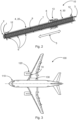
- Fig. 3 shows an aircraft 100 with a fuselage 110, a Hydrogen consumer 120 and a Hydrogen tank 130.
- the Hydrogen consumer is a turbine of the aircraft 100.
- the Hydrogen consumer 120 may be any consumer of gaseous Hydrogen.
- the gas distribution may be configured according to any one of the embodiments described herein.
Landscapes
- Engineering & Computer Science (AREA)
- General Engineering & Computer Science (AREA)
- Aviation & Aerospace Engineering (AREA)
- Mechanical Engineering (AREA)
- Filling Or Discharging Of Gas Storage Vessels (AREA)
Abstract
Description
- The present disclosure relates to gas distribution systems in general, and in particular to Hydrogen distribution systems for aircrafts.
- In light of environmental protection efforts, Hydrogen (H2) becomes increasingly important as an energy carrier. However, in aeronautic applications, such as in aircrafts, the strict requirements are particularly hard to fulfill.
- By nature, because of the lightweight construction of aircrafts, the aircraft itself during flight is a highly dynamic environment which deforms, e.g., during flight maneuvers or in turbulent atmosphere. Since any Hydrogen system in the aircraft needs to be attached to the aircraft in some way, these deformations are propagated to the Hydrogen system, and in particular to any piping/distribution system for the Hydrogen. Therefore, for such piping/distribution systems (such as in general for every piping within an airplane) such deformations need to be considered.
- The above is particularly important in light of a second main requirement for Hydrogen systems in aircrafts, namely the tightness of the system, to avoid leakages. Hydrogen is very volatile and, because of the small molecular cross section, diffuses through many materials, i.e., these materials are very permeable for Hydrogen. This problem is further amplified by the Hydrogen embrittlement occurring in many materials. Further, every standard sealed connection (i.e., bolted flange with O-rings, for example) cannot achieve a zero-leakage-rate, and even to gain a very low leakage rate, big efforts on design and stress are needed (e.g., with regard to the clamping forces, surface roughness, etc.). However, in particular in aircraft applications, the tightness of the system is very important to avoid fire hazards caused by Oxyhydrogen gas, which forms when leaking Hydrogen comes into contact with surrounding Oxygen. To further reduce such fire hazards (in addition to reducing leakage), ignition sources, such as sparking due to electrostatic discharges in the vicinity of Hydrogen leakages need to be avoided as far as possible.
- Currently, no technologies are known for an appropriate distribution system for Hydrogen within an aircraft, that accounts for the above problems. The double-walled distribution of fuel inside the fuselage, as is known in aviation, is not suitable for the distribution of Hydrogen within an aircraft due to the expected high leakage rates caused by the dynamic sealings used in such systems.
- It is an objective to provide a flexible gas distribution system for aircrafts with high mechanical compensation capabilities and low gas leakage and permeation.
- This objective is solved by the subject matter of the independent claims. Further embodiments are described in the dependent claims as well as in the following description.
- According to a first aspect, a gas distribution system for aircrafts is provided. The gas distribution system comprises a corrugated hose having a first connecting end and a second connecting end, and a shroud. The shroud surrounds the corrugated hose concentrically along a longitudinal direction of the corrugated hose, thereby building an intermediate space between the corrugated hose and the shroud. The first connecting end is configured to be connected to a gas tank. The second connecting end is configured to be connected to a gas consumer. The corrugated house is flexible so as to compensate for in-flight deflections of the gas distribution system.
- The gas distribution system functionally corresponds to a "piping system" for gaseous fuel.
- The corrugated hose is an elongated tube-like element that builds a conducting space for a fluid, such as gaseous fuel (e.g., gaseous Hydrogen). The corrugated hose may be a flexible cylindrical hollow element extending in a generally longitudinal direction and having corrugates or ripples/grooves that each extend in a circumferential direction of the corrugated hose, i.e., perpendicular to the longitudinal direction. Therefore, in a cross-section along the longitudinal direction, the corrugates build a wave-like pattern. As such, the corrugated hose is flexible in that sense, that it may compensate for deflections within the aircraft, i.e., yield to mechanical loads inserted into the corrugated hose. In other words, the corrugations allow for the corrugated hose to deform appropriately in response to mechanical loads acting onto the hose, such that the loads are compensated. Although described as a cylindrical element, it should be appreciated that a cross-section of the corrugated hose perpendicular to the longitudinal direction may also have shapes other than cylindrical, such as rectangular, square, or any other suitable shape.
- The corrugated hose may, in general, comprise or consist of a gas-tight material. In embodiments where the gas distribution system is used for Hydrogen, the corrugated hose may, in particular, comprise or consist of a material exhibiting a very low permeation for Hydrogen, such that diffusion of Hydrogen through the corrugated hose is reduced.
- Further, the corrugated hose may optionally comprise an inner liner, i.e., an additional flat but flexible layer (such as, for example, a foil). Such an inner liner may flatten the inner surface of the corrugated hose to avoid or reduce pressure losses and/or flow losses caused by turbulences that may otherwise occur at the corrugations of the corrugated hose when the fluid (e.g., Hydrogen) passes by.
- The first connecting end and the second connecting end both correspond to openings at opposite sides in the "tube" defined by the corrugated hose and act as inlet and outlet openings of the gas conducted/distributed by the gas distribution system, respectively. The first connecting end may, for example, be connected to an outlet of a gas tank. The second connecting end may be connected to an inlet of a gas consumer, for example (in the case of a Hydrogen distribution system) a Hydrogen consumer such as a corresponding turbine or any other consumer. Therefore, when mounted into a gas fuel system, the corrugated hose of the gas distribution system directs the gas from the gas tank to the gas consumer.
- However, it should be appreciated that the corrugated hose may also consist of multiple single corrugated hose elements that are added together. For example, a first corrugated hose element and a second corrugated hose element may be added together and sealed, such that the two corrugated hose elements together build the corrugated hose. In this case, the shroud also consists of corresponding single shroud elements surrounding the corresponding corrugated hose element. In such a configuration the second end of the first corrugated hose element is connected to the first end of the second corrugated hose element. The first end of the first corrugated hose element may then be connected to the gas tank and the second end of the second corrugated hose element may be connected to the gas consumer. Further, such a single corrugated hose element may have a branch or splitting point, such that, for example, two or more additional corrugated hose elements (and with it shroud elements) are connected to one end of the first corrugated hose element, thereby building a network of a gas distribution system comprising multiple corrugated hoses and corresponding shrouds. Each of the single gas distribution systems built in this way by the single corrugated hoses and shrouds may be configured according to any one of the embodiments described herein.
- Because the corrugated hose is flexible in the above manner, a single continuous (uninterrupted) hose between the gas tank and the gas consumer may be used. This avoids additional sealings within single segments, such as necessary in regular piping systems, and therefore avoids potentially additional leakage points at such sealings. The disclosed gas distribution system only needs sealings at the endings of the corrugated hose and shroud.
- The shroud surrounds the corrugated hose in a cladding-like manner concentrically and also extends in the longitudinal direction, in order to protect the corrugated hose and to establish the necessary mechanical stiffness. For this purpose, the shroud itself is non-flexible. The shroud and the corrugated hose together build an intermediate space between them in a radial direction, which may, for example (as described further below) be filled with a quenching medium, to decrease fire or explosion hazards. Just as the corrugated hose, the shroud is configured to be connected to a gas tank and a gas consumer on its respective ends. However, the shroud does not conduct the fuel gas. To build a sealed intermediate space, the ends of the shroud are sealed against the gas tank and the gas consumer, e.g., by means of conventional sealings.
- According to an embodiment, the gas distribution system further comprises a plurality of spacers in the intermediate space, keeping the corrugated hose and the shroud at a radial distance to each other and thereby avoiding chafing between the corrugated hose and the shroud. The spacers are spaced apart from each other along the longitudinal direction.
- Such spacers may, for example, be regular plastic spacers or other suitable spacers for holding the shroud at a defined radial distance to the corrugated hose.
- According to another embodiment, the gas distribution system further comprises at least one bellows connecting a first portion of the shroud with a second portion of the shroud, so that the first portion and the second portion are moveable with regard to each other.
- The at least one bellows may, for example, be a steel bellows which also has a wave-like cross-section in the longitudinal direction. The corrugated hose extends through the bellows without contacting it. The bellows itself is connected to the first portion and the second portion of the shroud and interconnects these portions with each other. In other words, the bellows defines a first section of the shroud and a second section of the shroud an connects these section with each other. Since the shroud itself, or rather the first portion and the second portion of the shroud are made from a stiff material (to provide the necessary mechanical overall stiffness), it is necessary to provide the shroud with compensation capabilities similar to those of the corrugated house. Therefore, the bellows may compensate for deflections (e.g., by slight deformations), while the shroud itself is stiff and mechanically supports the whole structure of the gas distribution system on a large scale. The bellows may be made from a gas tight (in particular embodiments especially hydrogen-tight) material providing low permeation of the gas. For example, the bellows may be made from steel.
- According to another embodiment, the intermediate space is filled with a quenching medium.
- Such a quenching medium separates the gas inside the corrugated hose from the surrounding air, and therefore from the Oxygen contained therein. When the gas inside the corrugated hose (in particular Hydrogen in certain embodiments) diffuses through the wall of the corrugated hose, the gas first enters the intermediate space and is mixed and diluted with the quenching medium. The quenching medium itself is an inert (chemically non-reactive) medium, which helps suppress building of dangerous gas mixtures of the gas with the surrounding Oxygen (if the gas inside the corrugated hose is Hydrogen, in particular the formation of Oxyhydrogen gas is avoided).
- According to another embodiment, the quenching medium is a quenching gas.
- Such a quenching gas may be any suitable inert gas, such as Nitrogen, Helium, Argon, Xenon, that helps to prevent formation of dangerous gas mixtures.
- According to another embodiment, the quenching gas is Nitrogen.
- Nitrogen is an inert gas that is suitable to avoid formation of Oxyhydrogen by avoiding contact between the gas conducted in the corrugated hose and the surrounding Oxygen.
- According to another embodiment, the shroud comprises at least two flushing openings for flushing the intermediate space and/or filling the intermediate space with a quenching medium.
- The flushing openings may be used to initially fill the intermediate space with the quenching medium after the gas distribution system has been installed between the gas tank and the gas consumer.
- Further, especially in Hydrogen applications, since Hydrogen diffusion through the walls of the corrugated hose is relatively high because of the small molecular cross section of the Hydrogen molecules, the quenching medium accumulates Hydrogen over time. Therefore, it may be necessary to exchange the quenching medium from time to time. For this purpose, for example, a first flushing opening may be present at one end of the shroud and a second flushing opening may be present at the other end of the shroud. The flushing openings are penetrating the shroud but do not penetrate the corrugated hose, such that the flushing openings are openings into the intermediate space from the outside of the gas distribution system. When the quenching medium is to be exchanged, new quenching medium may be pumped into one of the flushing openings and the old quenching medium may be removed through the other flushing opening, for example by means of a corresponding pump that can be connected to the flushing opening. When no exchange of the quenching medium takes place, the flushing opening may be closed and sealed with corresponding seals.
- According to another embodiment, the gas distribution system is a distribution system for gaseous Hydrogen.
- According to another embodiment, the corrugated hose comprises a material having a low permeability for Hydrogen.
- This decreases diffusion of Hydrogen from the corrugated hose into the intermediate space and therefore also to the outside.
- According to another embodiment, the corrugated hose comprises steel.
- Steel provides for a low permeation/diffusion of Hydrogen molecules and therefore is a preferred material for the corrugated hose and for the shroud. However, other low diffusion materials are conceivable, too. Further, steel is easy to weld and can be tested for Hydrogen-tightness. Also, steel by nature is electrically conductive and therefore decreases the probability of electrostatic discharges that might ignite Oxyhydrogen gas that might be present because it is in general not possible to have an absolutely Hydrogen-tight system. Therefore, using steel for the corrugated hose (and the shroud) decrease the risk of ignition and therefore of fires or explosions.
- According to another embodiment, the shroud comprises steel.
- Additionally to the low permeability for Hydrogen, steel for the shroud is in particular advantageous because the bellows preferably is made from steel, too. This allows for the shroud and the bellows to be welded together. Further, using steel for the shroud improves fire protection and mechanical protection for the corrugated hose because of the high fire resistance and good mechanical stability.
- According to another embodiment, the corrugated hose comprises an elastomer.
- Such an elastomer also provides low diffusion of Hydrogen and may be conceivable, too, although steel is the preferred material.
- According to another embodiment, the materials of the corrugated hose and of the shroud each comprise a very low tendency for electrostatic discharge.
- Such materials (e.g., steel, as described above) decrease the ignition risk.
- According to another embodiment, the first connecting end and the second connecting end each comprise a gas-tight sealing.
- Such a gas-tight sealings may be a conventional gas-tight sealing, such as O-rings. However, because the full distance between the gas tank and the gas consumer is covered by the corrugated hose, such conventional sealings can be used only at the connecting ends of the corrugated hose. Additional sealings connecting sections, such as in standard tubing systems, are avoided, thereby decreasing gas diffusion, and increasing gas-tightness of the gas distribution system.
- According to a second aspect, an aircraft is provided. The aircraft comprises a fuselage, a Hydrogen consumer, a Hydrogen tank, and a gas distribution system (10) as described above. The gas distribution system fluidly connects the Hydrogen tank with the Hydrogen consumer, so that the Hydrogen consumer receives Hydrogen from the Hydrogen tank via the gas distribution system.
- The Hydrogen consumer may, for example, be a Hydrogen turbine, a fuel cell, or any other Hydrogen consumer. The gas distribution system conducts gaseous Hydrogen from the Hydrogen tank to the Hydrogen consumer. The gas distribution may be configured according to any one of the embodiments described above.
- In summary, the present disclosure provides a gas distribution system, that is in particular suitable for Hydrogen conduction between a Hydrogen tank and a Hydrogen consumer in aircrafts, but may be used for other gases, too. The configuration of a single corrugated hose and a shroud with at least one bellows surrounding the house and defining an intermediate space between the shroud and the corrugated hose provides a gas distribution system, that compensates for deflections, for example during flight maneuvers, but still provides the necessary overall stiffness. Providing a quenching medium, such as a Nitrogen gas, within the intermediate space further decreases explosion risks caused by dangerous Oxyhydrogen gas formed by Hydrogen diffusion. The used materials for the components, in particular steel, further provide low electrostatic discharge probabilities, further enhancing fire and explosion protection. A bellows (preferably from steel) may further be used to compensate for deflections transferred via the shroud. Further, using steel for the bellows, too, adds to the fire protection and mechanical protection for the corrugated hose.
- In the following, exemplary embodiments are described in more detail having regard to the attached figures. The illustrations are schematic and not to scale. Identical reference signs refer to identical or similar elements. The figures show:
- Fig. 1
- A schematic view of a gas distribution system.
- Fig. 2
- A schematic cut view the gas distribution system of
Fig. 1 . - Fig. 3
- A schematic view of an aircraft comprising a Hydrogen consumer, a Hydrogen tank, and the gas distribution system of
Figs. 1 and2 . -
Figs. 1 and show agas distribution system 10 for Hydrogen for anaircraft 100.Fig. 1 shows a schematic isometric view of thegas distribution system 10.Fig. 2 shows a cut-view along alongitudinal direction 5 of thegas distribution system 10 ofFig. 1 . In the following,Figs. 1 and2 will be described together. - The
gas distribution system 10 comprises a corrugated hose 1 (best seen inFig. 2 ), a shroud 4 (best seen inFig. 1 ) and a bellows 8. The shroud 4 comprises a first portion 20 and a second portion 30. The first portion 20 and the second portion 30 of the shroud 4 are connected by thebellows 8. In the depicted configuration, thecorrugated hose 1 extends along the full length of thegas distribution system 10. However, as described further above, it should be appreciated that thecorrugated hose 1 as a whole may also consist of single corrugated hose elements added together. The shroud 4 (first portion 20 of the shroud 4 and second portion 30 of the shroud 4) as well as thebellows 8 surround thecorrugated hose 1 concentrically and along thelongitudinal direction 5 of thegas distribution system 10.Spacers 6 hold the shroud 4 at a defined radial distance to thecorrugated hose 1 and avoid chafing between thecorrugated hose 1 and the shroud 4. - The shroud 4 protects the
corrugated hose 1 and establishes the necessary mechanical stiffness. For this purpose, the shroud 4 itself is non-flexible. The shroud 4 and thecorrugated hose 1 together build anintermediate space 7 between them in a radial direction, which is (as described above and below) filled with a Nitrogen quenching gas, to decrease fire or explosion hazards. The shroud 4 is configured to be connected to a Hydrogen tank 130 (seeFig. 3 ) and aHydrogen consumer 120 on its respective ends. However, the shroud 4 does not conduct the Hydrogen. To build a sealedintermediate space 7, the ends of the shroud 4 are sealed against the Hydrogen tank 130 (Fig. 3 ) and the Hydrogen consumer 120 (Fig. 3 ), e.g., by means of conventional sealings atflanges 12. Theflanges 12 may, for example, be welded or bolted to theHydrogen tank 130 and theHydrogen consumer 120, respectively. - The
intermediate space 7 between thecorrugated hose 1 and the shroud 4 is filled with a Nitrogen quenching gas (not shown). Such a Nitrogen quenching gas separates the Hydrogen inside thecorrugated hose 1 from the surrounding air, and therefore from the Oxygen contained therein. When the Hydrogen inside thecorrugated hose 1 diffuses through the wall of thecorrugated hose 1, the Hydrogen first enters theintermediate space 7 and is mixed and diluted with the Nitrogen quenching gas. The Nitrogen quenching gas itself is an inert (chemically non-reactive) gas, which helps suppress formation of dangerous gas mixtures of the Hydrogen with the surrounding Oxygen (i.e., the formation of Oxyhydrogen), which would be an explosion risk. - A first connecting
end 2 of thecorrugated hose 1 is configured to be connected to a Hydrogen tank 130 (seeFig. 3 ). A second connectingend 3 of thecorrugated hose 1 is configured to be connected to aHydrogen consumer 120, such as a Hydrogen turbine (seeFig. 3 ). Therefore, thecorrugated hose 1 conducts the Hydrogen gas from theHydrogen tank 130 to theHydrogen consumer 120. - The
corrugated hose 1 is an elongated tube-like element that builds a conducting space for a fluid, such as gaseous fuel (e.g., gaseous Hydrogen in the shown example). Thecorrugated hose 1 is a flexible cylindrical hollow element extending generally in thelongitudinal direction 5 and havingcorrugates 9 or ripples/grooves 9 that each extend in acircumferential direction 11 of thecorrugated hose 1, i.e., perpendicular to thelongitudinal direction 5. Therefore, in a cross-section along the longitudinal direction (shown inFig. 2 ), thecorrugates 9 build a wave-like pattern. As such, thecorrugated hose 1 is flexible in that sense, that it may compensate for deflections within the aircraft, i.e., yield to mechanical loads inserted into thecorrugated hose 1 by slightly deforming. In other words, thecorrugates 9 allow for thecorrugated hose 1 to deform appropriately in response to mechanical loads acting onto thecorrugated hose 1, such that the loads are compensated. Although shown as a cylindrical element, it should be appreciated that a cross-section of thecorrugated hose 1 perpendicular to thelongitudinal direction 5 may also have shapes other than cylindrical, such as rectangular, square, or any other suitable shape. - The
bellows 8 as shown is a steel bellows 8 which also has a wave-like cross-section in the longitudinal direction 5 (seeFig. 2 ). In the shown configuration, thebellows 8 is surrounded by aprotective cover 13. Thecorrugated hose 1 extends through thebellows 8 without contacting it. Thebellows 8 itself is connected to the first portion 20 and the second portion 30 of the shroud and interconnects these portions with each other. In other words, thebellows 8 defines a first section of the shroud 4 and a second section of the shroud 4 an connects these section with each other. Since the shroud itself, or rather the first portion 20 and the second portion 30 of the shroud 4 are made from a stiff material (to provide the necessary mechanical stiffness overall), it is necessary to provide the shroud 4 with compensation capabilities similar to those of thecorrugated house 1. Therefore, thebellows 8 may compensate for deflections, while the shroud 4 itself is stiff and mechanically supports the whole structure of thegas distribution system 10 on a large scale. Thebellows 8 is made from a hydrogen-tight material providing low permeation of Hydrogen. In the configuration shown, thebellows 8 is made from steel. - The
corrugated hose 1 comprises or consists of a gas-tight material, preferably steel, exhibiting a very low permeation for Hydrogen, such that diffusion of Hydrogen through thecorrugated hose 1 is reduced. - Using steel for the
corrugated hose 1, for the shroud 4, and for thebellows 8 further enhances fire/explosion protection, because steel is electrically conducting and electrostatic discharges that might otherwise ignite Oxyhydrogen gases caused by diffusing Hydrogen are avoided. Also, steel provides for welded connections between the shroud 4 and thebellows 8 and between the connecting ends 2, 3 of thecorrugated hose 1 with end fittings for connecting to theHydrogen tank 130 and to theHydrogen consumer 120, respectively. - The disclosed gas distribution system decreases the amount of conventional sealings to an absolute minimum (only at the connecting ends 2, 3) and therefore enhances hydrogen-tightness.
-
Fig. 3 shows anaircraft 100 with afuselage 110, aHydrogen consumer 120 and aHydrogen tank 130. As shown, the Hydrogen consumer is a turbine of theaircraft 100. However, theHydrogen consumer 120 may be any consumer of gaseous Hydrogen. Agas distribution system 10, as described above, connects theHydrogen tank 130 with theHydrogen consumer 120. The gas distribution may be configured according to any one of the embodiments described herein. - It should be noted that "comprising" or "including" does not exclude other elements or steps, and "one" or "a" does not exclude a plurality. It should further be noted that features or steps that have been described with reference to any of the above embodiments may also be used in combination with other features or steps of other embodiments described above. Reference signs in the claims are not to be regarded as limitation.
-
- 1
- corrugated hose
- 2
- first connecting end
- 3
- second connecting end
- 4
- shroud
- 5
- longitudinal direction
- 6
- spacers
- 7
- intermediate space
- 8
- bellows
- 9
- corrugates
- 10
- Gas distribution system
- 11
- circumferential direction
- 12
- flanges
- 13
- protective cover
- 20
- first portion (of the shroud 4)
- 30
- second portion (of the shroud 4)
- 100
- Aircraft
- 110
- fuselage
- 120
- gas consumer, Hydrogen consumer
- 130
- gas tank, Hydrogen tank
Claims (15)
- A gas distribution system (10) for aircrafts (100), comprising:a corrugated hose (1) having a first connecting end (2) and a second connecting end (3); anda shroud (4) surrounding the corrugated hose (1) concentrically along a longitudinal direction (5) of the corrugated hose (1), thereby building an intermediate space (7) between the corrugated hose (1) and the shroud (4);wherein the first connecting end (2) is configured to be connected to a gas tank (130);wherein the second connecting end (3) is configured to be connected to a gas consumer (120);wherein the corrugated house (1) is flexible so as to compensate for in-flight deflections of the gas distribution system (10).
- The gas distribution system (10) of claim 1, further comprising a plurality of spacers (6) in the intermediate space (7), keeping the corrugated hose (1) and the shroud (4) at a radial distance to each other, wherein the spacers (6) are spaced apart from each other along the longitudinal direction (5).
- The gas distribution system (10) of any one of the preceding claims, further comprising at least one bellows (8) connecting a first portion (20) of the shroud (4) with a second portion (30) of the shroud (4), so that the first portion (20) and the second portion (30) are moveable with regard to each other.
- The gas distribution system (10) of any one of the preceding claims, wherein the intermediate space (7) is filled with a quenching medium.
- The gas distribution system (10) of claim 4, wherein the quenching medium is a quenching gas.
- The gas distribution system (10) of claim 5, wherein the quenching gas is Nitrogen.
- The gas distribution system (10) of any one of the preceding claims, wherein the shroud (4) comprises at least two flushing openings for flushing the intermediate space (7) and or filling the intermediate space (7) with a quenching medium.
- The gas distribution system (10) of any one of the preceding claims, wherein the gas distribution system (10) is a distribution system for gaseous Hydrogen.
- The gas distribution system (10) of claim 8, wherein the corrugated house (1) comprises a material having a low permeability for Hydrogen.
- The gas distribution system (10) of any one of the preceding claims, wherein the corrugated hose (1) comprises steel.
- The gas distribution system (10) of any one of the preceding claims, wherein the shroud (4) comprises steel.
- The gas distribution system (10) of any one of the preceding claims, wherein the corrugated hose (1) comprises an elastomer.
- The gas distribution system (10) of any one of the preceding claims, wherein the materials of the corrugated hose (1) and of the shroud (4) each comprise a very low tendency for electrostatic discharge.
- The gas distribution system (10) of any one of the preceding claims, wherein the first connecting end (2) and the second connecting end (3) each comprise a gas-tight sealing.
- Aircraft (100), comprising:a fuselage (110);a Hydrogen consumer (120);a Hydrogen tank (130); anda gas distribution system (10) according to any one of the preceding claims;wherein the gas distribution system (10) fluidly connects the Hydrogen tank (130) with the Hydrogen consumer (120), so that the Hydrogen consumer (120) receives Hydrogen from the Hydrogen tank (130) via the gas distribution system (10).
Priority Applications (3)
| Application Number | Priority Date | Filing Date | Title |
|---|---|---|---|
| EP23152996.7A EP4407223B1 (en) | 2023-01-24 | 2023-01-24 | Gas distribution system for aircrafts |
| US18/417,092 US20240246692A1 (en) | 2023-01-24 | 2024-01-19 | Gas distribution system for aircrafts |
| CN202410085024.5A CN118391589A (en) | 2023-01-24 | 2024-01-20 | Gas distribution system for an aircraft |
Applications Claiming Priority (1)
| Application Number | Priority Date | Filing Date | Title |
|---|---|---|---|
| EP23152996.7A EP4407223B1 (en) | 2023-01-24 | 2023-01-24 | Gas distribution system for aircrafts |
Publications (2)
| Publication Number | Publication Date |
|---|---|
| EP4407223A1 true EP4407223A1 (en) | 2024-07-31 |
| EP4407223B1 EP4407223B1 (en) | 2026-04-22 |
Family
ID=85076125
Family Applications (1)
| Application Number | Title | Priority Date | Filing Date |
|---|---|---|---|
| EP23152996.7A Active EP4407223B1 (en) | 2023-01-24 | 2023-01-24 | Gas distribution system for aircrafts |
Country Status (3)
| Country | Link |
|---|---|
| US (1) | US20240246692A1 (en) |
| EP (1) | EP4407223B1 (en) |
| CN (1) | CN118391589A (en) |
Citations (4)
| Publication number | Priority date | Publication date | Assignee | Title |
|---|---|---|---|---|
| US5600752A (en) * | 1994-03-11 | 1997-02-04 | Industrial Design Laboratories, Inc. | Flexible gas hose assembly with concentric helical tube members having reinforcement spring coils |
| EP2253878A1 (en) * | 2009-05-18 | 2010-11-24 | Nexans | Flexible conduit |
| DE102011010385A1 (en) * | 2011-02-05 | 2012-08-09 | Eads Deutschland Gmbh | Double-walled pipe and manufacturing process |
| US20130042478A1 (en) * | 2006-05-08 | 2013-02-21 | Bhp Billiton Petroleum Pty Ltd | Hose |
Family Cites Families (11)
| Publication number | Priority date | Publication date | Assignee | Title |
|---|---|---|---|---|
| US3410313A (en) * | 1965-05-04 | 1968-11-12 | New England Realty Co | Corrosion protected conduit system |
| US5829483A (en) * | 1992-10-30 | 1998-11-03 | Toyoda Gosei Co., Ltd. | Hose |
| US6279615B1 (en) * | 1999-09-03 | 2001-08-28 | Tokai Rubber Industries, Ltd. | Fuel hose |
| WO2003044413A1 (en) * | 2001-11-20 | 2003-05-30 | Dqp, Llc | A leak-free flexible conduit |
| EP2146125B1 (en) * | 2008-07-17 | 2011-11-02 | Nexans | Flexible conduit pipe |
| EP2653770B1 (en) * | 2012-04-20 | 2018-07-25 | TI Automotive (Heidelberg) GmbH | Connector, in particular quick connector |
| US9163772B2 (en) * | 2012-07-02 | 2015-10-20 | Varian Semiconductor Equipment Associates, Inc. | Vacuum insulated cryogenic fluid transfer hose |
| US8893748B2 (en) * | 2012-11-08 | 2014-11-25 | Linde Aktiengesellschaft | Pipeline for high pressure cryogenic applications |
| KR101718904B1 (en) * | 2015-02-13 | 2017-03-23 | 한국과학기술원 | Transfer line for ultra-cold fluid |
| EP3670997B1 (en) * | 2018-12-19 | 2022-07-06 | Nexans | Flexible vacuum insulated conduit |
| KR102149400B1 (en) * | 2019-10-10 | 2020-08-31 | 주식회사 유니온기업 | Flexible pipe and manufacturing methor thereof |
-
2023
- 2023-01-24 EP EP23152996.7A patent/EP4407223B1/en active Active
-
2024
- 2024-01-19 US US18/417,092 patent/US20240246692A1/en active Pending
- 2024-01-20 CN CN202410085024.5A patent/CN118391589A/en active Pending
Patent Citations (4)
| Publication number | Priority date | Publication date | Assignee | Title |
|---|---|---|---|---|
| US5600752A (en) * | 1994-03-11 | 1997-02-04 | Industrial Design Laboratories, Inc. | Flexible gas hose assembly with concentric helical tube members having reinforcement spring coils |
| US20130042478A1 (en) * | 2006-05-08 | 2013-02-21 | Bhp Billiton Petroleum Pty Ltd | Hose |
| EP2253878A1 (en) * | 2009-05-18 | 2010-11-24 | Nexans | Flexible conduit |
| DE102011010385A1 (en) * | 2011-02-05 | 2012-08-09 | Eads Deutschland Gmbh | Double-walled pipe and manufacturing process |
Also Published As
| Publication number | Publication date |
|---|---|
| EP4407223B1 (en) | 2026-04-22 |
| US20240246692A1 (en) | 2024-07-25 |
| CN118391589A (en) | 2024-07-26 |
Similar Documents
| Publication | Publication Date | Title |
|---|---|---|
| US12319429B2 (en) | Double-wall hydrogen pipeline comprising at least one system for detecting a leak at at least one coupling system, and aircraft comprising at least one such pipeline | |
| US12060965B2 (en) | Optimized connection assembly between two portions of a supply line for a cryogenic fluid, including an additional thermal insulation chamber and a fluid expansion chamber | |
| US12240622B2 (en) | Aircraft assembly | |
| EP4249380B1 (en) | Fuel line safety protection system | |
| RU2333380C2 (en) | Rotary cryotechnical sleeve, cryogenic liquid feed line and rocket engine | |
| CN108298111A (en) | A kind of common platform satellite chemical propulsion subsystem modular layout method | |
| US12296974B2 (en) | Aircraft | |
| CN101305231B (en) | Cryogenic pipeline structure and method | |
| EP4407223B1 (en) | Gas distribution system for aircrafts | |
| CN115552166B (en) | Liquid dome comprising a liquefied gas storage tank provided with an opening with an additional cover | |
| US7641068B2 (en) | Liquid hydrogen storage tank with common-access tube as port for pipes into the inner vessel | |
| CN113932070A (en) | Hydrogen gas delivery system and hydrogen gas delivery method | |
| JP2025524408A (en) | Safety support system for fuel cell modules | |
| US20240200713A1 (en) | Fuel Line Comprising Insulation, and Pressure Vessel System | |
| US12613012B2 (en) | Double-wall tank | |
| CN219714177U (en) | Gas blowing and gas sealing integrated system and low-temperature carrier rocket | |
| US20250224078A1 (en) | Demountable aeronautical liquefied gas storage device | |
| EP4040035B1 (en) | Hydrogen storage tank with leak management functionality | |
| CN117329368A (en) | Hydrogen pipe coupling device with enhanced internal tightness | |
| EP4650639A1 (en) | Fluid assembly | |
| EP4325107B1 (en) | Fluid transport device and method for assembling and disassembling a fluid transport device | |
| US20240313342A1 (en) | Energy storage venting device | |
| US20260036244A1 (en) | Vacuum-insulated pipe assembly | |
| CN113056633B (en) | Storage facility for liquefied gas | |
| US20250224080A1 (en) | Aeronautical device for storing liquefied gas having a collector |
Legal Events
| Date | Code | Title | Description |
|---|---|---|---|
| PUAI | Public reference made under article 153(3) epc to a published international application that has entered the european phase |
Free format text: ORIGINAL CODE: 0009012 |
|
| STAA | Information on the status of an ep patent application or granted ep patent |
Free format text: STATUS: THE APPLICATION HAS BEEN PUBLISHED |
|
| AK | Designated contracting states |
Kind code of ref document: A1 Designated state(s): AL AT BE BG CH CY CZ DE DK EE ES FI FR GB GR HR HU IE IS IT LI LT LU LV MC ME MK MT NL NO PL PT RO RS SE SI SK SM TR |
|
| STAA | Information on the status of an ep patent application or granted ep patent |
Free format text: STATUS: REQUEST FOR EXAMINATION WAS MADE |
|
| 17P | Request for examination filed |
Effective date: 20250131 |
|
| STAA | Information on the status of an ep patent application or granted ep patent |
Free format text: STATUS: EXAMINATION IS IN PROGRESS |
|
| 17Q | First examination report despatched |
Effective date: 20250910 |
|
| GRAP | Despatch of communication of intention to grant a patent |
Free format text: ORIGINAL CODE: EPIDOSNIGR1 |
|
| STAA | Information on the status of an ep patent application or granted ep patent |
Free format text: STATUS: GRANT OF PATENT IS INTENDED |
|
| RIC1 | Information provided on ipc code assigned before grant |
Ipc: F16L 11/15 20060101AFI20260210BHEP Ipc: B64D 37/30 20060101ALI20260210BHEP Ipc: F16L 51/02 20060101ALN20260210BHEP |
|
| GRAS | Grant fee paid |
Free format text: ORIGINAL CODE: EPIDOSNIGR3 |
|
| GRAA | (expected) grant |
Free format text: ORIGINAL CODE: 0009210 |
|
| STAA | Information on the status of an ep patent application or granted ep patent |
Free format text: STATUS: THE PATENT HAS BEEN GRANTED |
|
| INTG | Intention to grant announced |
Effective date: 20260220 |
|
| AK | Designated contracting states |
Kind code of ref document: B1 Designated state(s): AL AT BE BG CH CY CZ DE DK EE ES FI FR GB GR HR HU IE IS IT LI LT LU LV MC ME MK MT NL NO PL PT RO RS SE SI SK SM TR |
|
| REG | Reference to a national code |
Ref country code: CH Ref legal event code: F10 Free format text: ST27 STATUS EVENT CODE: U-0-0-F10-F00 (AS PROVIDED BY THE NATIONAL OFFICE) Effective date: 20260422 Ref country code: GB Ref legal event code: FG4D |
|
| REG | Reference to a national code |
Ref country code: DE Ref legal event code: R096 Ref document number: 602023015511 Country of ref document: DE |