EP4407220A1 - Method and device for measuring valve characteristic parameters - Google Patents
Method and device for measuring valve characteristic parameters Download PDFInfo
- Publication number
- EP4407220A1 EP4407220A1 EP22793833.9A EP22793833A EP4407220A1 EP 4407220 A1 EP4407220 A1 EP 4407220A1 EP 22793833 A EP22793833 A EP 22793833A EP 4407220 A1 EP4407220 A1 EP 4407220A1
- Authority
- EP
- European Patent Office
- Prior art keywords
- valve
- drive current
- push rod
- measuring
- motor
- Prior art date
- Legal status (The legal status is an assumption and is not a legal conclusion. Google has not performed a legal analysis and makes no representation as to the accuracy of the status listed.)
- Granted
Links
Images



Classifications
-
- F—MECHANICAL ENGINEERING; LIGHTING; HEATING; WEAPONS; BLASTING
- F16—ENGINEERING ELEMENTS AND UNITS; GENERAL MEASURES FOR PRODUCING AND MAINTAINING EFFECTIVE FUNCTIONING OF MACHINES OR INSTALLATIONS; THERMAL INSULATION IN GENERAL
- F16K—VALVES; TAPS; COCKS; ACTUATING-FLOATS; DEVICES FOR VENTING OR AERATING
- F16K37/00—Special means in or on valves or other cut-off apparatus for indicating or recording operation thereof, or for enabling an alarm to be given
- F16K37/0025—Electrical or magnetic means
- F16K37/0041—Electrical or magnetic means for measuring valve parameters
-
- F—MECHANICAL ENGINEERING; LIGHTING; HEATING; WEAPONS; BLASTING
- F16—ENGINEERING ELEMENTS AND UNITS; GENERAL MEASURES FOR PRODUCING AND MAINTAINING EFFECTIVE FUNCTIONING OF MACHINES OR INSTALLATIONS; THERMAL INSULATION IN GENERAL
- F16K—VALVES; TAPS; COCKS; ACTUATING-FLOATS; DEVICES FOR VENTING OR AERATING
- F16K37/00—Special means in or on valves or other cut-off apparatus for indicating or recording operation thereof, or for enabling an alarm to be given
- F16K37/0075—For recording or indicating the functioning of a valve in combination with test equipment
- F16K37/0083—For recording or indicating the functioning of a valve in combination with test equipment by measuring valve parameters
-
- F—MECHANICAL ENGINEERING; LIGHTING; HEATING; WEAPONS; BLASTING
- F16—ENGINEERING ELEMENTS AND UNITS; GENERAL MEASURES FOR PRODUCING AND MAINTAINING EFFECTIVE FUNCTIONING OF MACHINES OR INSTALLATIONS; THERMAL INSULATION IN GENERAL
- F16K—VALVES; TAPS; COCKS; ACTUATING-FLOATS; DEVICES FOR VENTING OR AERATING
- F16K31/00—Actuating devices; Operating means; Releasing devices
- F16K31/02—Actuating devices; Operating means; Releasing devices electric; magnetic
- F16K31/04—Actuating devices; Operating means; Releasing devices electric; magnetic using a motor
-
- G—PHYSICS
- G01—MEASURING; TESTING
- G01R—MEASURING ELECTRIC VARIABLES; MEASURING MAGNETIC VARIABLES
- G01R31/00—Arrangements for testing electric properties; Arrangements for locating electric faults; Arrangements for electrical testing characterised by what is being tested not provided for elsewhere
- G01R31/28—Testing of electronic circuits, e.g. by signal tracer
- G01R31/282—Testing of electronic circuits specially adapted for particular applications not provided for elsewhere
Definitions
- the present invention in general relates to the field of valve controllers, and in particular to a method and device for measuring valve characteristic parameters of a valve actuator.
- Valves are widely used in heating, ventilation, and air conditioning systems (HVAC), and a valve actuator controls the flow by controlling the position of a valve.
- HVAC heating, ventilation, and air conditioning systems
- Different valves have different sizes, stroke lengths, seal types, dead zone lengths, etc.
- a valve is controlled by a dedicated valve controller, and there is no need to measure the characteristic parameters of the valve (stroke length, dead zone length, etc.).
- Valve controls of different types or even with different characteristic parameters cannot be used interchangeably.
- Some manufacturers use mechanical means such as flaps to increase the versatility of valve actuators, but there is still a huge limitation.
- the present invention provides a method and a device for measuring valve characteristic parameters, so as to improve the versatility of valve actuators.
- the present invention provides a method for measuring valve characteristic parameters of a valve actuator, wherein the valve characteristic parameters comprise a stroke length of the valve, the valve actuator is used to drive the valve and comprises a push rod driven by a motor, the push rod is adapted to push a valve rod of the valve, and the motor is connected to a current sensor, which is adapted to measure a DC drive current flowing into the motor, and the measuring method comprises: resetting the push rod to a top end position; driving the push rod to push the valve rod, measuring the DC drive current in real time, and recording a first position of the push rod at the start of a first abrupt change in the DC drive current when the first abrupt change in the DC drive current is detected and lasts for more than a first preset time period; continuing to drive the push rod to push the valve rod and measure the DC drive current in real time, and recording a second position of the push rod at the start of a second abrupt change in the DC drive current when the second abrupt change in the DC drive current is detected and lasts for more than
- the valve characteristic parameters further comprise a dead zone length
- the measuring method further comprises: continuing to drive the push rod to push the valve rod and measure an output driving force of the motor in real time, recording a third position of the push rod when the output driving force reaches a preset output force, and calculating the dead zone length of the valve based on the second position and the third position.
- the DC drive current curve may be used to determine the dead zone length of the valve, thereby making it possible to use the valve actuator in valves of different types.
- the valve actuator also has a position sensor, which is used to detect the drive shaft position of the motor, and the measuring method comprises: measuring the drive shaft position of the motor by the position sensor, and converting the drive shaft position to a position of the push rod.
- the position of the push rod may be obtained through the position of the drive shaft of the motor, which reduces the complexity of the structure.
- the measuring method comprises: measuring the DC drive current in real time, calculating an average change rate of the DC drive current, and identifying the first abrupt change and/or the second abrupt change in the DC drive current when an instantaneous change rate is greater than the average change rate. For this, abrupt changes in the DC drive current are measured.
- the measuring method comprises: repeating the measuring method a plurality of times, and taking the measurement result as a characteristic parameter of the valve when the results of the plurality of times of measurement in the measuring method are consistent. For this, a plurality of measurements can improve the accuracy of the measurement result.
- the present invention also provides a device for measuring valve characteristic parameters of a valve actuator, wherein the valve characteristic parameters comprise a stroke length of the valve, the valve actuator is used to drive the valve and comprises a push rod driven by a motor, the push rod is adapted to push a valve rod of the valve, and the motor is connected to a current sensor, which is adapted to measure a DC drive current flowing into the motor, and the measuring device comprises: a resetting module, which resets the push rod to a top end position; a first recording module, which, when the push rod is driven to push the valve rod and the DC drive current is measured in real time, records a first position of the push rod at the start of a first abrupt change in the DC drive current when the first abrupt change in the DC drive current is detected and lasts for more than a first preset time period; a second recording module, which, when the push rod continues to be driven to push the valve rod and the DC drive current continues to be measured in real time, records a second position of the push rod at the start of a second abrupt
- the valve characteristic parameters further comprise a dead zone length
- the measuring device further comprises: when the push rod continues to be driven to push the valve rod and an output driving force of the motor is measured in real time, recording a third position of the push rod when the output driving force reaches a preset output force, and calculating the dead zone length of the valve based on the second position and the third position.
- the valve actuator also has a position sensor, which is used to detect the drive shaft position of the motor, and the measuring device comprises: measuring the drive shaft position of the motor by the position sensor, and converting the drive shaft position to a position of the push rod.
- the measuring device comprises: measuring the DC drive current in real time, calculating an average change rate of the DC drive current, and identifying the first abrupt change and/or the second abrupt change in the DC drive current when an instantaneous change rate is greater than the average change rate.
- the measuring device comprises: repeating the functions of the measuring device a plurality of times, and taking the measurement result as a characteristic parameter of the valve when the results of the plurality of times of measurement by the measuring device are consistent.
- the present invention also provides a valve actuator, which has a measuring device as described above.
- the present invention also provides an electronic device, comprising a processor, a memory and an instruction stored in the memory, wherein the instruction, when executed by the processor, implements the method as described above.
- the present invention also provides a computer-readable storage medium, with a computer instruction stored therein, which, when run, executes the method as described above.
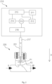
- FIG. 2 is a schematic diagram of a valve actuator 210 and a valve 220 according to one embodiment of the present invention.
- the valve actuator 210 is used to drive the valve 220.
- the valve 220 may be a normally open valve, which is normally open by default, i.e., in the fully open position, and the valve 220 is partially opened or closed under the drive of the valve actuator 210.
- the valve 220 may also be a normally closed valve, which is normally closed by default, i.e., in the fully closed position, and the valve 220 is partially or fully opened under the drive of the valve actuator 210.
- a normally open valve will be used as an example below.
- the valve actuator 210 comprises a power supply 211, a current sensor 212, a motor 213, a position sensor 214, a processing unit 215, a speed change mechanism 216 and a push rod 217.
- the power supply 211 is used to supply power to the motor 213, and the current sensor 212 is arranged on the circuit between the power supply 211 and the motor 213.
- the current sensor 212 is adapted to measure the DC drive current flowing into the motor 213.
- the motor 213 may be an integrated motor, i.e., integrated with the actuator, which can reduce the volume and cost of the motor 213.
- the position sensor 214 is connected to the motor 213 and the processing unit 215, and is adapted to measure the drive shaft position of the motor 213 and send the drive shaft position to the processing unit 215.
- the processing unit 215 is connected to the current sensor 212 and the position sensor 214, to receive and process the data sent by the current sensor 212 and the position sensor 214.
- the motor 213, the speed change mechanism 216 and the push rod 217 are connected in sequence, so that the push rod 217 can move under the drive of the motor 213.
- the push rod 217 is adapted to push the valve rod 221 of the valve 220.
- the valve 220 is used to enable, disable or regulate the flow of fluid in a pipeline.
- the valve comprises a push rod 221 which is adapted to move in the closing direction D.
- the valve 220 is fully opened when the valve rod 221 is at the top end position P1, and the valve 220 is closed when the valve rod 221 moves along the closing direction D to contact the bottom end position P2.
- the distance between the top end position P1 and the bottom end position P2 is the stroke length of the valve 220.
- the valve rod 221 can continue to move from the position where it is in contact with the bottom end position P2 to the stop position P3 (not shown in the figure).
- the distance between the bottom end position P2 and the stop position P3 is the dead zone length of the valve 220.
- valves 220 usually have different stroke lengths and dead zone lengths, and valves of different types or even different characteristic parameters cannot be used interchangeably.
- the embodiments of the present invention make it possible to use the actuator in different types of valves by measuring the stroke length and dead zone length of the valve.
- the present invention provides a method 100 for measuring valve characteristic parameters of a valve actuator, and the valve characteristic parameters comprise the stroke length of a valve.
- Figure 1 is a flowchart of a measuring method 100 according to one embodiment of the present invention. As shown in Figure 1 , the measuring method comprises: Step 110, resetting the push rod to a top end position. The push rod 217 is probably not in the top end position initially, and is reset to the top end position. When the push rod 217 reaches the top end position from a middle position, the DC drive current detected by the current sensor 212 will change abruptly. By detecting an abrupt change in the DC drive current, it can be determined that the push rod 217 has reached the top end position.
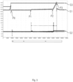
- FIG. 3 is a schematic diagram of the DC drive current according to one embodiment of the present invention, wherein the abscissa is the time, in milliseconds (ms), and the ordinate is the DC drive current, in milliamperes (mA).
- S1 is the curve of the DC drive current
- S2 is the curve of the rate of change of the DC drive current.
- Step 120 driving the push rod to push the valve rod, measuring the DC drive current in real time, and recording a first position of the push rod at the start of a first abrupt change in the DC drive current when the first abrupt change in the DC drive current is detected and lasts for more than a first preset time period.
- the push rod 217 is driven to move toward the closing direction D of the valve 220, and the DC drive current is measured in real time.
- the position of the push rod at the start of the first abrupt change in the DC drive current is where the push rod 217 and the valve rod 221 start to contact, i.e., the valve rod 221 is in the top end position, until the push rod 217 is fully joined with the valve rod 221, and the first position VP1 of the push rod at the start of the first abrupt change in the DC drive current is recorded.
- the position sensor 214 can detect the drive shaft position of the motor 213 and convert the drive shaft position into the first position VP1 of the push rod 217. In some embodiments, by measuring the DC drive current in real time and calculating the average rate of change (for example, the root mean square) of the DC drive current, the first abrupt change in the first DC drive current is identified when the instantaneous rate of change is greater than the average rate of change.
- the average rate of change for example, the root mean square
- Step 130 continuing to drive the push rod to push the valve rod and measure the DC drive current in real time, and recording a second position of the push rod at the start of a second abrupt change in the DC drive current when the second abrupt change in the DC drive current is detected and lasts for more than a second preset time period.
- the push rod 217 continues to be driven to move toward the closing direction D of the valve 220, and the DC drive current is measured in real time.
- the position of the push rod at the start of the second abrupt change in the DC drive current is where the valve rod 221 comes into contact with the bottom end position, and the second position VP2 of the push rod at the start of the second abrupt change in the DC drive current is recorded.
- the position sensor can detect the drive shaft position of the motor and convert the drive shaft position into the position of the push rod.
- the position sensor 214 can detect the drive shaft position of the motor 213 and convert the drive shaft position into the second position VP2 of the push rod 217. In some embodiments, by measuring the DC drive current in real time and calculating the average rate of change (for example, the root mean square) of the DC drive current, the second abrupt change in the first DC drive current is identified when the instantaneous rate of change is greater than the average rate of change.
- the average rate of change for example, the root mean square
- Step 140 calculating the stroke length of the valve based on the first position and the second position.
- the first position VP1 is the position where the push rod 217 and the valve rod 221 start to contact, i.e., the valve rod 221 is in the top end position
- the second position VP2 is the position where the valve rod 221 contacts the bottom end position.
- the stroke length of the valve can be calculated by subtracting the first position VP1 from the second position VP2.
- the valve characteristic parameters further comprise a dead zone length
- the measuring method further comprises: continuing to drive the push rod to push the valve rod and measure an output driving force of the motor in real time, recording a third position of the push rod when the output driving force reaches a preset output force, and calculating the dead zone length of the valve based on the second position and the third position. Based on the required force for fully closing the valve, the valve is deemed to be tightly closed when the output driving force reaches a preset output force.
- the push rod 217 continues to be driven to move in the closing direction D of the valve 220, and the DC drive current is measured in real time.
- the position of the push rod is where the valve rod 221 stops, and the third position VP3 of the push rod is recorded.
- the third position VP3 is where the valve rod 221 reaches the stop position.
- the dead zone length of the valve can be calculated by subtracting the second position VP2 from the third position VP3.
- the position sensor can detect the drive shaft position of the motor and convert the drive shaft position into the position of the push rod.
- the position sensor 214 can detect the drive shaft position of the motor 213 and convert the drive shaft position into the third position VP3 of the push rod 217.
- the measuring method comprises: repeating the measuring method a plurality of times, and taking the measurement result as a characteristic parameter of the valve when the results of the plurality of times of measurement in the measuring method are consistent. This can improve the accuracy of the measurement result.
- the embodiments of the present invention provide a method for measuring valve characteristic parameters of a valve actuator, wherein a current sensor is used to measure the DC drive current of the motor in real time, and the DC drive current curve is used to determine the characteristic parameter of the valve, thereby making it possible to use the valve actuator in valves of different types.
- FIG. 4 is a schematic diagram of a measuring device 400 according to one embodiment of the present invention. As shown in Figure 4 , the measuring device 400 comprises:
- the valve characteristic parameters further comprise a dead zone length
- the measuring device further comprises: continuing to drive the push rod to push the valve rod and measure an output driving force of the motor in real time, recording a third position of the push rod when the output driving force reaches a preset output force, and calculating the dead zone length of the valve based on the second position and the third position.
- the valve actuator also has a position sensor, which is used to detect the drive shaft position of the motor, and the measuring device comprises: measuring the drive shaft position of the motor by the position sensor, and converting the drive shaft position to a position of the push rod.
- the measuring device comprises: measuring the DC drive current in real time, calculating the average rate of change of the DC drive current, and identifying the first and/or the second abrupt change in the first DC drive current when the instantaneous rate of change is greater than the average rate of change.
- the measuring device comprises: repeating the measuring method a plurality of times, and taking the measurement result as a characteristic parameter of the valve when the results of the plurality of times of measurement in the measuring method are consistent.
- the present invention also provides a valve actuator, which has a measuring device 400 as described above.
- FIG. 5 is a schematic diagram of an electronic device 500 according to one embodiment of the present invention.
- the electronic device 500 comprises a processor 510 and a memory 520, with an instruction stored in the memory 520, wherein the instruction, when executed by the processor 510, implements the method 100 as described above.
- the present invention also provides a computer-readable storage medium, with a computer instruction stored therein, which, when run, executes the method 100 as described above.
- Some aspects of the method and the device of the present invention may be implemented entirely by hardware or entirely by software (including firmware, resident software, microcode, etc.), or by a combination thereof.
- the above hardware or software may be referred to as a "data block”, “module”, “engine”, “unit”, “component” or “system”.
- the processor may be one or more application specific integrated circuits (ASICs), digital signal processors (DSPs), digital signal processing devices (DAPDs), programmable logic devices (PLDs), field programmable gate arrays (FPGAs), processors, controllers, microcontrollers, microprocessors, or a combination thereof.
- ASICs application specific integrated circuits
- DSPs digital signal processors
- DAPDs digital signal processing devices
- PLDs programmable logic devices
- FPGAs field programmable gate arrays
- processors controllers, microcontrollers, microprocessors, or a combination thereof.
- all aspects of the present invention may be embodied as a computer product comprising
- the computer-readable media may include but are not limited to magnetic storage devices (for example, hard disks, floppy disks, magnetic tapes, etc.), optical disks (for example, compact discs (CDs), digital versatile disks (DVDs), etc.), and smart cards and flash memory devices (for example, cards, sticks, key drives, etc.).
- magnetic storage devices for example, hard disks, floppy disks, magnetic tapes, etc.
- optical disks for example, compact discs (CDs), digital versatile disks (DVDs), etc.
- smart cards and flash memory devices for example, cards, sticks, key drives, etc.
Landscapes
- Engineering & Computer Science (AREA)
- General Engineering & Computer Science (AREA)
- Mechanical Engineering (AREA)
- Physics & Mathematics (AREA)
- General Physics & Mathematics (AREA)
- Indication Of The Valve Opening Or Closing Status (AREA)
- Electrically Driven Valve-Operating Means (AREA)
- Testing Of Devices, Machine Parts, Or Other Structures Thereof (AREA)
- Investigating Or Analyzing Materials By The Use Of Electric Means (AREA)
Abstract
Description
- The present invention in general relates to the field of valve controllers, and in particular to a method and device for measuring valve characteristic parameters of a valve actuator.
- Valves are widely used in heating, ventilation, and air conditioning systems (HVAC), and a valve actuator controls the flow by controlling the position of a valve. Different valves have different sizes, stroke lengths, seal types, dead zone lengths, etc. In the prior art, a valve is controlled by a dedicated valve controller, and there is no need to measure the characteristic parameters of the valve (stroke length, dead zone length, etc.). Valve controls of different types or even with different characteristic parameters cannot be used interchangeably. Some manufacturers use mechanical means such as flaps to increase the versatility of valve actuators, but there is still a huge limitation.
- To solve the above technical problem, the present invention provides a method and a device for measuring valve characteristic parameters, so as to improve the versatility of valve actuators.
- To achieve the above purpose, the present invention provides a method for measuring valve characteristic parameters of a valve actuator, wherein the valve characteristic parameters comprise a stroke length of the valve, the valve actuator is used to drive the valve and comprises a push rod driven by a motor, the push rod is adapted to push a valve rod of the valve, and the motor is connected to a current sensor, which is adapted to measure a DC drive current flowing into the motor, and the measuring method comprises: resetting the push rod to a top end position; driving the push rod to push the valve rod, measuring the DC drive current in real time, and recording a first position of the push rod at the start of a first abrupt change in the DC drive current when the first abrupt change in the DC drive current is detected and lasts for more than a first preset time period; continuing to drive the push rod to push the valve rod and measure the DC drive current in real time, and recording a second position of the push rod at the start of a second abrupt change in the DC drive current when the second abrupt change in the DC drive current is detected and lasts for more than a second preset time period; calculating the stroke length of the valve based on the first position and the second position. For this, a current sensor is used to measure the DC drive current of the motor in real time, and the DC drive current curve is used to determine the characteristic parameter of the valve, thereby making it possible to use the valve actuator in valves of different types.
- Preferably, the valve characteristic parameters further comprise a dead zone length, and the measuring method further comprises: continuing to drive the push rod to push the valve rod and measure an output driving force of the motor in real time, recording a third position of the push rod when the output driving force reaches a preset output force, and calculating the dead zone length of the valve based on the second position and the third position. For this, the DC drive current curve may be used to determine the dead zone length of the valve, thereby making it possible to use the valve actuator in valves of different types.
- Preferably, the valve actuator also has a position sensor, which is used to detect the drive shaft position of the motor, and the measuring method comprises: measuring the drive shaft position of the motor by the position sensor, and converting the drive shaft position to a position of the push rod. For this, the position of the push rod may be obtained through the position of the drive shaft of the motor, which reduces the complexity of the structure.
- Preferably, the measuring method comprises: measuring the DC drive current in real time, calculating an average change rate of the DC drive current, and identifying the first abrupt change and/or the second abrupt change in the DC drive current when an instantaneous change rate is greater than the average change rate. For this, abrupt changes in the DC drive current are measured.
- Preferably, the measuring method comprises: repeating the measuring method a plurality of times, and taking the measurement result as a characteristic parameter of the valve when the results of the plurality of times of measurement in the measuring method are consistent. For this, a plurality of measurements can improve the accuracy of the measurement result.
- The present invention also provides a device for measuring valve characteristic parameters of a valve actuator, wherein the valve characteristic parameters comprise a stroke length of the valve, the valve actuator is used to drive the valve and comprises a push rod driven by a motor, the push rod is adapted to push a valve rod of the valve, and the motor is connected to a current sensor, which is adapted to measure a DC drive current flowing into the motor, and the measuring device comprises: a resetting module, which resets the push rod to a top end position; a first recording module, which, when the push rod is driven to push the valve rod and the DC drive current is measured in real time, records a first position of the push rod at the start of a first abrupt change in the DC drive current when the first abrupt change in the DC drive current is detected and lasts for more than a first preset time period; a second recording module, which, when the push rod continues to be driven to push the valve rod and the DC drive current continues to be measured in real time, records a second position of the push rod at the start of a second abrupt change in the DC drive current when the second abrupt change in the DC drive current is detected and lasts for more than a second preset time period; a calculating module, which calculates the stroke length of the valve based on the first position and the second position.
- Preferably, the valve characteristic parameters further comprise a dead zone length, and the measuring device further comprises: when the push rod continues to be driven to push the valve rod and an output driving force of the motor is measured in real time, recording a third position of the push rod when the output driving force reaches a preset output force, and calculating the dead zone length of the valve based on the second position and the third position.
- Preferably, the valve actuator also has a position sensor, which is used to detect the drive shaft position of the motor, and the measuring device comprises: measuring the drive shaft position of the motor by the position sensor, and converting the drive shaft position to a position of the push rod.
- Preferably, the measuring device comprises: measuring the DC drive current in real time, calculating an average change rate of the DC drive current, and identifying the first abrupt change and/or the second abrupt change in the DC drive current when an instantaneous change rate is greater than the average change rate.
- Preferably, the measuring device comprises: repeating the functions of the measuring device a plurality of times, and taking the measurement result as a characteristic parameter of the valve when the results of the plurality of times of measurement by the measuring device are consistent.
- The present invention also provides a valve actuator, which has a measuring device as described above.
- The present invention also provides an electronic device, comprising a processor, a memory and an instruction stored in the memory, wherein the instruction, when executed by the processor, implements the method as described above.
- The present invention also provides a computer-readable storage medium, with a computer instruction stored therein, which, when run, executes the method as described above.
- The following drawings are only intended to illustrate and explain the present invention schematically, and do not limit the scope of the present invention. In the drawings,
-
Figure 1 is a flowchart of a measuring method according to one embodiment of the present invention; -
Figure 2 is a schematic diagram of a valve actuator and a valve according to one embodiment of the present invention; -
Figure 3 is a schematic diagram of the DC drive current according to one embodiment of the present invention; -
Figure 4 is a schematic diagram of a measuring device according to one embodiment of the present invention; -
Figure 5 is a schematic diagram of an electronic device according to one embodiment of the present invention. -
- 100 Measuring method
- 110-140 Steps
- 210 Valve actuator
- 211 Power supply
- 212 Current sensor
- 213 Motor
- 214 Position sensor
- 215 Processing unit
- 216 Speed change mechanism
- 217 Push rod
- 220 Valve
- 221 Valve rod
- D Valve closing direction
- P1 First position
- P2 Second position
- 400 Measuring module
- 410 Resetting module
- 420 First recording module
- 430 Second recording module
- 440 Calculating module
- 500 Electronic device
- 510 Processor
- 520 Memory
- In order to have a clearer understanding of the technical features, purpose and effects of the present invention, the specific embodiments of the present invention will be described below with reference to the drawings.
- In the following description, many specific details are provided in order to fully understand the present invention. However, the present invention may also be implemented in other ways different from those described herein. Therefore, the present invention is not limited to the specific embodiments disclosed below.
- As shown in this patent application and the claims, unless the context clearly dictates otherwise, terms "a", "an", "one" and/or "the" are not intended to be specific in the singular and may include the plural. Generally, terms "comprising" and "including" only imply that the clearly identified steps and elements are included, these steps and elements do not constitute an exclusive list, and the method or device may also include other steps or elements.
-
Figure 2 is a schematic diagram of avalve actuator 210 and avalve 220 according to one embodiment of the present invention. Thevalve actuator 210 is used to drive thevalve 220. Thevalve 220 may be a normally open valve, which is normally open by default, i.e., in the fully open position, and thevalve 220 is partially opened or closed under the drive of thevalve actuator 210. Thevalve 220 may also be a normally closed valve, which is normally closed by default, i.e., in the fully closed position, and thevalve 220 is partially or fully opened under the drive of thevalve actuator 210. To simplify the description, a normally open valve will be used as an example below. - The
valve actuator 210 comprises apower supply 211, acurrent sensor 212, amotor 213, aposition sensor 214, aprocessing unit 215, aspeed change mechanism 216 and apush rod 217. Thepower supply 211 is used to supply power to themotor 213, and thecurrent sensor 212 is arranged on the circuit between thepower supply 211 and themotor 213. For this purpose, thecurrent sensor 212 is adapted to measure the DC drive current flowing into themotor 213. Themotor 213 may be an integrated motor, i.e., integrated with the actuator, which can reduce the volume and cost of themotor 213. Theposition sensor 214 is connected to themotor 213 and theprocessing unit 215, and is adapted to measure the drive shaft position of themotor 213 and send the drive shaft position to theprocessing unit 215. Theprocessing unit 215 is connected to thecurrent sensor 212 and theposition sensor 214, to receive and process the data sent by thecurrent sensor 212 and theposition sensor 214. Themotor 213, thespeed change mechanism 216 and thepush rod 217 are connected in sequence, so that thepush rod 217 can move under the drive of themotor 213. Thepush rod 217 is adapted to push thevalve rod 221 of thevalve 220. - The
valve 220 is used to enable, disable or regulate the flow of fluid in a pipeline. The valve comprises apush rod 221 which is adapted to move in the closing direction D. Thevalve 220 is fully opened when thevalve rod 221 is at the top end position P1, and thevalve 220 is closed when thevalve rod 221 moves along the closing direction D to contact the bottom end position P2. The distance between the top end position P1 and the bottom end position P2 is the stroke length of thevalve 220. For elastic materials, thevalve rod 221 can continue to move from the position where it is in contact with the bottom end position P2 to the stop position P3 (not shown in the figure). The distance between the bottom end position P2 and the stop position P3 is the dead zone length of thevalve 220. Different types ofvalves 220 usually have different stroke lengths and dead zone lengths, and valves of different types or even different characteristic parameters cannot be used interchangeably. The embodiments of the present invention make it possible to use the actuator in different types of valves by measuring the stroke length and dead zone length of the valve. - The present invention provides a
method 100 for measuring valve characteristic parameters of a valve actuator, and the valve characteristic parameters comprise the stroke length of a valve.Figure 1 is a flowchart of ameasuring method 100 according to one embodiment of the present invention. As shown inFigure 1 , the measuring method comprises:
Step 110, resetting the push rod to a top end position. Thepush rod 217 is probably not in the top end position initially, and is reset to the top end position. When thepush rod 217 reaches the top end position from a middle position, the DC drive current detected by thecurrent sensor 212 will change abruptly. By detecting an abrupt change in the DC drive current, it can be determined that thepush rod 217 has reached the top end position.Figure 3 is a schematic diagram of the DC drive current according to one embodiment of the present invention, wherein the abscissa is the time, in milliseconds (ms), and the ordinate is the DC drive current, in milliamperes (mA). S1 is the curve of the DC drive current, and S2 is the curve of the rate of change of the DC drive current. As shown inFigure 3 , when thepush rod 217 reaches the top end position P0, the DC drive current curve S1 suddenly rises, which is also reflected in the change rate curve S2 of the DC drive current. -
Step 120, driving the push rod to push the valve rod, measuring the DC drive current in real time, and recording a first position of the push rod at the start of a first abrupt change in the DC drive current when the first abrupt change in the DC drive current is detected and lasts for more than a first preset time period. - The
push rod 217 is driven to move toward the closing direction D of thevalve 220, and the DC drive current is measured in real time. As shown inFigure 3 , when the DC drive current has the first abrupt change that lasts for more than the first preset time period, the position of the push rod at the start of the first abrupt change in the DC drive current is where thepush rod 217 and thevalve rod 221 start to contact, i.e., thevalve rod 221 is in the top end position, until thepush rod 217 is fully joined with thevalve rod 221, and the first position VP1 of the push rod at the start of the first abrupt change in the DC drive current is recorded. In some embodiments, theposition sensor 214 can detect the drive shaft position of themotor 213 and convert the drive shaft position into the first position VP1 of thepush rod 217. In some embodiments, by measuring the DC drive current in real time and calculating the average rate of change (for example, the root mean square) of the DC drive current, the first abrupt change in the first DC drive current is identified when the instantaneous rate of change is greater than the average rate of change. -
Step 130, continuing to drive the push rod to push the valve rod and measure the DC drive current in real time, and recording a second position of the push rod at the start of a second abrupt change in the DC drive current when the second abrupt change in the DC drive current is detected and lasts for more than a second preset time period. - The
push rod 217 continues to be driven to move toward the closing direction D of thevalve 220, and the DC drive current is measured in real time. As shown inFigure 3 , when the DC drive current has the second abrupt change that lasts for more than the second preset time period, the position of the push rod at the start of the second abrupt change in the DC drive current is where thevalve rod 221 comes into contact with the bottom end position, and the second position VP2 of the push rod at the start of the second abrupt change in the DC drive current is recorded. In some embodiments, the position sensor can detect the drive shaft position of the motor and convert the drive shaft position into the position of the push rod. In some embodiments, theposition sensor 214 can detect the drive shaft position of themotor 213 and convert the drive shaft position into the second position VP2 of thepush rod 217. In some embodiments, by measuring the DC drive current in real time and calculating the average rate of change (for example, the root mean square) of the DC drive current, the second abrupt change in the first DC drive current is identified when the instantaneous rate of change is greater than the average rate of change. -
Step 140, calculating the stroke length of the valve based on the first position and the second position. - The first position VP1 is the position where the
push rod 217 and thevalve rod 221 start to contact, i.e., thevalve rod 221 is in the top end position, and the second position VP2 is the position where thevalve rod 221 contacts the bottom end position. The stroke length of the valve can be calculated by subtracting the first position VP1 from the second position VP2. - In some embodiments, the valve characteristic parameters further comprise a dead zone length, and the measuring method further comprises: continuing to drive the push rod to push the valve rod and measure an output driving force of the motor in real time, recording a third position of the push rod when the output driving force reaches a preset output force, and calculating the dead zone length of the valve based on the second position and the third position. Based on the required force for fully closing the valve, the valve is deemed to be tightly closed when the output driving force reaches a preset output force.
- Specifically, the
push rod 217 continues to be driven to move in the closing direction D of thevalve 220, and the DC drive current is measured in real time. As shown inFigure 3 , when the output driving force reaches the preset output force, the position of the push rod is where thevalve rod 221 stops, and the third position VP3 of the push rod is recorded. The third position VP3 is where thevalve rod 221 reaches the stop position. The dead zone length of the valve can be calculated by subtracting the second position VP2 from the third position VP3. In some embodiments, the position sensor can detect the drive shaft position of the motor and convert the drive shaft position into the position of the push rod. In some embodiments, theposition sensor 214 can detect the drive shaft position of themotor 213 and convert the drive shaft position into the third position VP3 of thepush rod 217. - In some embodiments, the measuring method comprises: repeating the measuring method a plurality of times, and taking the measurement result as a characteristic parameter of the valve when the results of the plurality of times of measurement in the measuring method are consistent. This can improve the accuracy of the measurement result.
- The table below shows the measurement results using the measuring method in the embodiments of the present invention. It can be seen that the measuring method in the embodiments of the present invention is very accurate.
Type of valve Rated stroke length VP1 (mm) VP2 (mm) Stroke length (mm) VP3 (mm) Dead zone length (mm) WP4 6 .20F1 .4 4.5mm 1.810 6.399 4.589 6.845 0.445 1.845 6.401 4.557 6.852 0.451 1.846 6.403 4.558 6.860 0.456 1.858 6.404 4.547 6.866 0.462 1.850 6.403 4.553 6.860 0.456 VXI4 6 .25/2 2.5mm 2.194 4.703 2.509 4.933 0.230 2.193 4.707 2.514 4.923 0.216 2.199 4.706 2.506 4.932 0.226 2.205 4.708 2.503 4.933 0.225 2.198 4.707 2.509 4.930 0.223 - The embodiments of the present invention provide a method for measuring valve characteristic parameters of a valve actuator, wherein a current sensor is used to measure the DC drive current of the motor in real time, and the DC drive current curve is used to determine the characteristic parameter of the valve, thereby making it possible to use the valve actuator in valves of different types.
- The present invention also provides a device for measuring valve characteristic parameters of a valve actuator.
Figure 4 is a schematic diagram of ameasuring device 400 according to one embodiment of the present invention. As shown inFigure 4 , the measuringdevice 400 comprises: - a
resetting module 410, which resets the push rod to a top end position; - a
first recording module 420, which, when the push rod is driven to push the valve rod and the DC drive current is measured in real time, records a first position of the push rod at the start of a first abrupt change in the DC drive current when the first abrupt change in the DC drive current is detected and lasts for more than a first preset time period; - a
second recording module 430, which, when the push rod continues to be driven to push the valve rod and the DC drive current continues to be measured in real time, records a second position of the push rod at the start of a second abrupt change in the DC drive current when the second abrupt change in the DC drive current is detected and lasts for more than a second preset time period; and - a calculating
module 440, which calculates the stroke length of the valve based on the first position and the second position. - In some embodiments, the valve characteristic parameters further comprise a dead zone length, and the measuring device further comprises: continuing to drive the push rod to push the valve rod and measure an output driving force of the motor in real time, recording a third position of the push rod when the output driving force reaches a preset output force, and calculating the dead zone length of the valve based on the second position and the third position.
- In some embodiments, the valve actuator also has a position sensor, which is used to detect the drive shaft position of the motor, and the measuring device comprises: measuring the drive shaft position of the motor by the position sensor, and converting the drive shaft position to a position of the push rod.
- In some embodiments, the measuring device comprises: measuring the DC drive current in real time, calculating the average rate of change of the DC drive current, and identifying the first and/or the second abrupt change in the first DC drive current when the instantaneous rate of change is greater than the average rate of change.
- In some embodiments, the measuring device comprises: repeating the measuring method a plurality of times, and taking the measurement result as a characteristic parameter of the valve when the results of the plurality of times of measurement in the measuring method are consistent.
- The present invention also provides a valve actuator, which has a
measuring device 400 as described above. - The present invention also provides an
electronic device 500.Figure 5 is a schematic diagram of anelectronic device 500 according to one embodiment of the present invention. As shown inFigure 5 , theelectronic device 500 comprises aprocessor 510 and amemory 520, with an instruction stored in thememory 520, wherein the instruction, when executed by theprocessor 510, implements themethod 100 as described above. - The present invention also provides a computer-readable storage medium, with a computer instruction stored therein, which, when run, executes the
method 100 as described above. - Some aspects of the method and the device of the present invention may be implemented entirely by hardware or entirely by software (including firmware, resident software, microcode, etc.), or by a combination thereof. The above hardware or software may be referred to as a "data block", "module", "engine", "unit", "component" or "system". The processor may be one or more application specific integrated circuits (ASICs), digital signal processors (DSPs), digital signal processing devices (DAPDs), programmable logic devices (PLDs), field programmable gate arrays (FPGAs), processors, controllers, microcontrollers, microprocessors, or a combination thereof. In addition, all aspects of the present invention may be embodied as a computer product comprising computer-readable program code in one or more computer-readable media. For example, the computer-readable media may include but are not limited to magnetic storage devices (for example, hard disks, floppy disks, magnetic tapes, etc.), optical disks (for example, compact discs (CDs), digital versatile disks (DVDs), etc.), and smart cards and flash memory devices (for example, cards, sticks, key drives, etc.).
- Flowcharts are used herein to illustrate the operations performed by the method according to the embodiments of this patent application. It should be understood that these operations are not necessarily performed exactly in the order shown. Instead, the various steps may be processed in the reverse order or simultaneously. At the same time, other operations may be added to these processes, or a step or some steps may be removed from these processes.
- It should be understood that, although this description is given according to the various embodiments, it is not necessary that each embodiment contains only one independent technical solution. This way of description is only for clarity, and those skilled in the art should regard the description as a whole. The technical solutions in each embodiment can also be appropriately combined to form other implementations that can be understood by those skilled in the art.
- The above are only illustrative specific embodiments of the present invention and are not intended to limit the scope of the present invention. Any equivalent changes, modifications and combinations made by anyone skilled in the art without departing from the concept and principle of the present invention shall fall within the scope of the present invention.
Claims (13)
- A method (100) for measuring valve characteristic parameters of a valve actuator, the valve characteristic parameters comprising a stroke length of the valve, the valve actuator being used to drive the valve and comprising a push rod driven by a motor, the push rod being adapted to push a valve rod of the valve, and the motor being connected to a current sensor, which is adapted to measure a DC drive current of the motor, wherein the measuring method (100) comprises:- resetting the push rod to a top end position (110);- driving the push rod to push the valve rod, measuring the DC drive current in real time, and recording a first position of the push rod at the start of a first abrupt change in the DC drive current when the first abrupt change in the DC drive current is detected and lasts for more than a first preset time period (120);- continuing to drive the push rod to push the valve rod and measure the DC drive current in real time, and recording a second position of the push rod at the start of a second abrupt change in the DC drive current when the second abrupt change in the DC drive current is detected and lasts for more than a second preset time period (130);- calculating the stroke length of the valve based on the first position and the second position (140).
- The measuring method (100) as claimed in claim 1, wherein the valve characteristic parameters further comprise a dead zone length, and the measuring method (100) further comprises: continuing to drive the push rod to push the valve rod and measure an output driving force of the motor in real time, recording a third position of the push rod when the output driving force reaches a preset output force, and calculating the dead zone length of the valve based on the second position and the third position.
- The measuring method (100) as claimed in claim 1 or 2, wherein the valve actuator also has a position sensor, which is used to detect the drive shaft position of the motor, and the measuring method (100) comprises: measuring the drive shaft position of the motor by the position sensor, and converting the drive shaft position to a position of the push rod.
- The measuring method (100) as claimed in claim 1 or 2, wherein the measuring method (100) comprises: measuring the DC drive current in real time, calculating an average change rate of the DC drive current, and identifying the first abrupt change and/or the second abrupt change in the DC drive current when an instantaneous change rate is greater than the average change rate.
- The measuring method (100) as claimed in claim 1 or 2, wherein the measuring method (100) comprises: repeating the measuring method (100) a plurality of times, and taking the measurement result as a characteristic parameter of the valve when the results of the plurality of times of measurement in the measuring method (100) are consistent.
- A device (400) for measuring valve characteristic parameters of a valve actuator, wherein the valve characteristic parameters comprise a stroke length of the valve, the valve actuator is used to drive the valve and comprises a push rod driven by a motor, the push rod is adapted to push a valve rod of the valve, and the motor is connected to a current sensor, which is adapted to measure a DC drive current of the motor, wherein the measuring device (400) comprises:- a resetting module (410), which resets the push rod to a top end position;- a first recording module (420), which, when the push rod is driven to push the valve rod and the DC drive current is measured in real time, records a first position of the push rod at the start of a first abrupt change in the DC drive current when the first abrupt change in the DC drive current is detected and lasts for more than a first preset time period;- a second recording module (430), which, when the push rod continues to be driven to push the valve rod and the DC drive current continues to be measured in real time, records a second position of the push rod at the start of a second abrupt change in the DC drive current when the second abrupt change in the DC drive current is detected and lasts for more than a second preset time period; and- a calculating module (440), which calculates the stroke length of the valve based on the first position and the second position.
- The measuring device (400) as claimed in claim 6, wherein the valve characteristic parameters further comprise a dead zone length, and the measuring device (400) further comprises: when the push rod continues to be driven to push the valve rod and an output driving force of the motor is measured in real time, recording a third position of the push rod when the output driving force reaches a preset output force, and calculating the dead zone length of the valve based on the second position and the third position.
- The measuring device (400) as claimed in claim 6 or 7, wherein the valve actuator also has a position sensor, which is used to detect the drive shaft position of the motor, and the measuring device (400) comprises: measuring the drive shaft position of the motor by the position sensor, and converting the drive shaft position to a position of the push rod.
- The measuring device (400) as claimed in claim 6 or 7, wherein the measuring device (400) comprises: measuring the DC drive current in real time, calculating an average change rate of the DC drive current, and identifying the first abrupt change and/or the second abrupt change in the DC drive current when an instantaneous change rate is greater than the average change rate.
- The measuring device (400) as claimed in claim 6 or 7, wherein the measuring device (400) comprises: repeating the functions of the measuring device (400) a plurality of times, and taking the measurement result as a characteristic parameter of the valve when the results of the plurality of times of measurement by the measuring device (400) are consistent.
- A valve actuator, wherein the valve actuator has a measuring device as claimed in any of claims 6 to 10.
- An electronic device (500), comprising a processor (510), a memory (520) and an instruction stored in the memory (520), wherein the instruction, when executed by the processor (510), implements the method as claimed in any of claims 1 to 5.
- A computer-readable storage medium, with a computer instruction stored therein, which, when run, executes the method as claimed in any of claims 1 to 5.
Applications Claiming Priority (2)
| Application Number | Priority Date | Filing Date | Title |
|---|---|---|---|
| CN202111124284.1A CN115931339A (en) | 2021-09-24 | 2021-09-24 | Method and device for detecting valve characteristic parameters |
| PCT/IB2022/058422 WO2023052875A1 (en) | 2021-09-24 | 2022-09-07 | Method and device for measuring valve characteristic parameters |
Publications (2)
| Publication Number | Publication Date |
|---|---|
| EP4407220A1 true EP4407220A1 (en) | 2024-07-31 |
| EP4407220B1 EP4407220B1 (en) | 2026-01-28 |
Family
ID=83995687
Family Applications (1)
| Application Number | Title | Priority Date | Filing Date |
|---|---|---|---|
| EP22793833.9A Active EP4407220B1 (en) | 2021-09-24 | 2022-09-07 | Method and device for measuring valve characteristic parameters |
Country Status (8)
| Country | Link |
|---|---|
| US (1) | US20240384813A1 (en) |
| EP (1) | EP4407220B1 (en) |
| KR (1) | KR20240056645A (en) |
| CN (1) | CN115931339A (en) |
| AU (1) | AU2022357513B2 (en) |
| DK (1) | DK4407220T3 (en) |
| TW (1) | TWI855373B (en) |
| WO (1) | WO2023052875A1 (en) |
Families Citing this family (1)
| Publication number | Priority date | Publication date | Assignee | Title |
|---|---|---|---|---|
| CN117013891B (en) * | 2023-10-07 | 2024-01-16 | 深圳市锐同技术有限公司 | Load point judging method, device, equipment and storage medium |
Family Cites Families (9)
| Publication number | Priority date | Publication date | Assignee | Title |
|---|---|---|---|---|
| US4879901A (en) * | 1987-08-20 | 1989-11-14 | Liberty Technology Center, Inc. | System for evaluating the condition and performance of a valve and valve operator combination |
| US5140853A (en) * | 1988-01-19 | 1992-08-25 | Westinghouse Electric Corp. | Method and apparatus for monitoring and measuring dynamic loads in thrust inducing systems |
| JP3246878B2 (en) * | 1996-08-06 | 2002-01-15 | 日立建機株式会社 | Segment assembly equipment |
| NO334421B1 (en) * | 2009-08-20 | 2014-03-03 | Vetco Gray Scandinavia As | Electrically operated valve actuator with electromechanical device for detecting end stops |
| DE102017208273A1 (en) * | 2017-05-17 | 2018-11-22 | Robert Bosch Gmbh | Method for switching a solenoid valve |
| US11226053B2 (en) * | 2018-08-28 | 2022-01-18 | Johnson Controls Tyco IP Holdings LLP | Valve assembly with pressure disturbance rejection and fault detection and diagnosis |
| EP3745009B1 (en) * | 2019-05-29 | 2023-07-05 | Georg Fischer Rohrleitungssysteme AG | Commissioning of a diaphragm valve |
| US12370395B2 (en) * | 2020-03-16 | 2025-07-29 | Tyco Fire & Security Gmbh | Thermoelectric tripping device and coupling arrangement thereof |
| CN112728195B (en) * | 2021-01-14 | 2024-04-12 | 华东理工大学 | Electric valve and torque and stroke measuring system and method of actuator of electric valve |
-
2021
- 2021-09-24 CN CN202111124284.1A patent/CN115931339A/en active Pending
-
2022
- 2022-09-06 TW TW111133694A patent/TWI855373B/en active
- 2022-09-07 KR KR1020247012903A patent/KR20240056645A/en active Pending
- 2022-09-07 WO PCT/IB2022/058422 patent/WO2023052875A1/en not_active Ceased
- 2022-09-07 AU AU2022357513A patent/AU2022357513B2/en active Active
- 2022-09-07 EP EP22793833.9A patent/EP4407220B1/en active Active
- 2022-09-07 US US18/693,394 patent/US20240384813A1/en active Pending
- 2022-09-07 DK DK22793833.9T patent/DK4407220T3/en active
Also Published As
| Publication number | Publication date |
|---|---|
| EP4407220B1 (en) | 2026-01-28 |
| DK4407220T3 (en) | 2026-03-30 |
| KR20240056645A (en) | 2024-04-30 |
| TW202317963A (en) | 2023-05-01 |
| CN115931339A (en) | 2023-04-07 |
| AU2022357513B2 (en) | 2025-08-21 |
| WO2023052875A1 (en) | 2023-04-06 |
| TWI855373B (en) | 2024-09-11 |
| US20240384813A1 (en) | 2024-11-21 |
| AU2022357513A1 (en) | 2024-03-14 |
Similar Documents
| Publication | Publication Date | Title |
|---|---|---|
| US11098917B2 (en) | Method for controlling fresh air machine and fresh air machine | |
| JP5107843B2 (en) | Plunger position detection device and solenoid valve | |
| US12146580B2 (en) | Actuator and method of operating the actuator | |
| CN105783350A (en) | Control method and device for air conditioner electronic expansion valve | |
| CN104329509B (en) | Smart valve and its control method | |
| CN101749296A (en) | Method and air-operated valve for determining wear condition of valve through pressure sensing | |
| US9509243B2 (en) | Automatic actuator calibration using back EMF | |
| US20160139608A1 (en) | Feedback-controlled fluid valve | |
| KR20180026031A (en) | Failure diagnosis method and system of temperature sensor for switching unit | |
| CN102606799B (en) | Valve gear and the method for operation valve | |
| JP6581833B2 (en) | Actuator failure detection device, control device and method | |
| US20240384813A1 (en) | Method and Device for Measuring Valve Characteristic Parameters | |
| US20220034424A1 (en) | Method of diagnosing a valve, diagnosis module, and valve | |
| CN116931610A (en) | A fast response method and device for pressure control | |
| KR20140011328A (en) | Method and device for checking a control device | |
| CN116657121A (en) | Process chamber pressure control equipment calibration method, calibration device and semiconductor process equipment | |
| KR20090094030A (en) | Disk drive and tray control mechanism | |
| CN115413988A (en) | Humidity control method and device for cleaning equipment, cleaning equipment and storage medium | |
| US20250137854A1 (en) | Method and device for checking the plausibility of a temperature in a component of an electrical machine in a technical system | |
| CN117614428A (en) | A field effect tube over-temperature protection method, device, system, equipment and medium | |
| CN117028640A (en) | Control method and control device of electric valve | |
| CN114813081A (en) | A performance detection system and detection method of a rotary valve actuator | |
| CN207795378U (en) | A kind of motor thermosistor and engine system with error-disable function | |
| CN110748687A (en) | Method for converting forward and reverse rotation switching valve driver into regulated quantity output | |
| JP2016056725A (en) | Steam turbine, control method and program |
Legal Events
| Date | Code | Title | Description |
|---|---|---|---|
| STAA | Information on the status of an ep patent application or granted ep patent |
Free format text: STATUS: UNKNOWN |
|
| STAA | Information on the status of an ep patent application or granted ep patent |
Free format text: STATUS: THE INTERNATIONAL PUBLICATION HAS BEEN MADE |
|
| PUAI | Public reference made under article 153(3) epc to a published international application that has entered the european phase |
Free format text: ORIGINAL CODE: 0009012 |
|
| STAA | Information on the status of an ep patent application or granted ep patent |
Free format text: STATUS: REQUEST FOR EXAMINATION WAS MADE |
|
| 17P | Request for examination filed |
Effective date: 20240318 |
|
| AK | Designated contracting states |
Kind code of ref document: A1 Designated state(s): AL AT BE BG CH CY CZ DE DK EE ES FI FR GB GR HR HU IE IS IT LI LT LU LV MC MK MT NL NO PL PT RO RS SE SI SK SM TR |
|
| DAV | Request for validation of the european patent (deleted) | ||
| DAX | Request for extension of the european patent (deleted) | ||
| GRAP | Despatch of communication of intention to grant a patent |
Free format text: ORIGINAL CODE: EPIDOSNIGR1 |
|
| STAA | Information on the status of an ep patent application or granted ep patent |
Free format text: STATUS: GRANT OF PATENT IS INTENDED |
|
| RIC1 | Information provided on ipc code assigned before grant |
Ipc: F16K 37/00 20060101AFI20251009BHEP Ipc: F16K 31/04 20060101ALI20251009BHEP Ipc: G01R 31/28 20060101ALI20251009BHEP |
|
| INTG | Intention to grant announced |
Effective date: 20251023 |
|
| GRAS | Grant fee paid |
Free format text: ORIGINAL CODE: EPIDOSNIGR3 |
|
| GRAA | (expected) grant |
Free format text: ORIGINAL CODE: 0009210 |
|
| STAA | Information on the status of an ep patent application or granted ep patent |
Free format text: STATUS: THE PATENT HAS BEEN GRANTED |
|
| AK | Designated contracting states |
Kind code of ref document: B1 Designated state(s): AL AT BE BG CH CY CZ DE DK EE ES FI FR GB GR HR HU IE IS IT LI LT LU LV MC MK MT NL NO PL PT RO RS SE SI SK SM TR |
|
| REG | Reference to a national code |
Ref country code: CH Ref legal event code: F10 Free format text: ST27 STATUS EVENT CODE: U-0-0-F10-F00 (AS PROVIDED BY THE NATIONAL OFFICE) Effective date: 20260128 Ref country code: GB Ref legal event code: FG4D |
|
| REG | Reference to a national code |
Ref country code: DE Ref legal event code: R096 Ref document number: 602022029399 Country of ref document: DE |
|
| REG | Reference to a national code |
Ref country code: IE Ref legal event code: FG4D |
|
| P01 | Opt-out of the competence of the unified patent court (upc) registered |
Free format text: CASE NUMBER: UPC_APP_0005387_4407220/2026 Effective date: 20260213 |
|
| REG | Reference to a national code |
Ref country code: DK Ref legal event code: T3 Effective date: 20260326 |