EP4407208A1 - Live-ventilanordnung - Google Patents
Live-ventilanordnung Download PDFInfo
- Publication number
- EP4407208A1 EP4407208A1 EP24153670.5A EP24153670A EP4407208A1 EP 4407208 A1 EP4407208 A1 EP 4407208A1 EP 24153670 A EP24153670 A EP 24153670A EP 4407208 A1 EP4407208 A1 EP 4407208A1
- Authority
- EP
- European Patent Office
- Prior art keywords
- poppet
- fluid pathway
- fluid
- valve
- assembly
- Prior art date
- Legal status (The legal status is an assumption and is not a legal conclusion. Google has not performed a legal analysis and makes no representation as to the accuracy of the status listed.)
- Pending
Links
- 239000012530 fluid Substances 0.000 claims abstract description 142
- 230000037361 pathway Effects 0.000 claims abstract description 64
- 238000013016 damping Methods 0.000 claims abstract description 31
- 230000035939 shock Effects 0.000 claims description 118
- 239000000725 suspension Substances 0.000 claims description 48
- 230000006835 compression Effects 0.000 claims description 15
- 238000007906 compression Methods 0.000 claims description 15
- 238000007789 sealing Methods 0.000 claims description 9
- 230000003071 parasitic effect Effects 0.000 claims description 6
- 230000000694 effects Effects 0.000 claims description 5
- XLYOFNOQVPJJNP-UHFFFAOYSA-N water Substances O XLYOFNOQVPJJNP-UHFFFAOYSA-N 0.000 claims description 3
- 230000000712 assembly Effects 0.000 description 10
- 238000000429 assembly Methods 0.000 description 10
- 230000033001 locomotion Effects 0.000 description 9
- 238000004891 communication Methods 0.000 description 6
- 230000002452 interceptive effect Effects 0.000 description 5
- 238000012986 modification Methods 0.000 description 4
- 230000004048 modification Effects 0.000 description 4
- 239000011435 rock Substances 0.000 description 3
- IJGRMHOSHXDMSA-UHFFFAOYSA-N Atomic nitrogen Chemical compound N#N IJGRMHOSHXDMSA-UHFFFAOYSA-N 0.000 description 2
- 230000003044 adaptive effect Effects 0.000 description 2
- 230000009194 climbing Effects 0.000 description 2
- 238000005461 lubrication Methods 0.000 description 2
- 238000000034 method Methods 0.000 description 2
- 230000036316 preload Effects 0.000 description 2
- 238000005096 rolling process Methods 0.000 description 2
- 230000009192 sprinting Effects 0.000 description 2
- 238000011144 upstream manufacturing Methods 0.000 description 2
- 229910000831 Steel Inorganic materials 0.000 description 1
- RTAQQCXQSZGOHL-UHFFFAOYSA-N Titanium Chemical compound [Ti] RTAQQCXQSZGOHL-UHFFFAOYSA-N 0.000 description 1
- 239000006096 absorbing agent Substances 0.000 description 1
- 230000001133 acceleration Effects 0.000 description 1
- 230000000903 blocking effect Effects 0.000 description 1
- 238000001816 cooling Methods 0.000 description 1
- 238000005336 cracking Methods 0.000 description 1
- 238000005516 engineering process Methods 0.000 description 1
- 238000007667 floating Methods 0.000 description 1
- 239000007789 gas Substances 0.000 description 1
- 239000010720 hydraulic oil Substances 0.000 description 1
- 238000005259 measurement Methods 0.000 description 1
- 229910052757 nitrogen Inorganic materials 0.000 description 1
- 238000002360 preparation method Methods 0.000 description 1
- 230000000284 resting effect Effects 0.000 description 1
- 230000033764 rhythmic process Effects 0.000 description 1
- 230000001020 rhythmical effect Effects 0.000 description 1
- 239000004576 sand Substances 0.000 description 1
- 229920006395 saturated elastomer Polymers 0.000 description 1
- 239000010959 steel Substances 0.000 description 1
- 229910052719 titanium Inorganic materials 0.000 description 1
- 239000010936 titanium Substances 0.000 description 1
Images


Classifications
-
- F—MECHANICAL ENGINEERING; LIGHTING; HEATING; WEAPONS; BLASTING
- F16—ENGINEERING ELEMENTS AND UNITS; GENERAL MEASURES FOR PRODUCING AND MAINTAINING EFFECTIVE FUNCTIONING OF MACHINES OR INSTALLATIONS; THERMAL INSULATION IN GENERAL
- F16F—SPRINGS; SHOCK-ABSORBERS; MEANS FOR DAMPING VIBRATION
- F16F9/00—Springs, vibration-dampers, shock-absorbers, or similarly-constructed movement-dampers using a fluid or the equivalent as damping medium
- F16F9/32—Details
- F16F9/50—Special means providing automatic damping adjustment, i.e. self-adjustment of damping by particular sliding movements of a valve element, other than flexions or displacement of valve discs; Special means providing self-adjustment of spring characteristics
- F16F9/512—Means responsive to load action, i.e. static load on the damper or dynamic fluid pressure changes in the damper, e.g. due to changes in velocity
-
- F—MECHANICAL ENGINEERING; LIGHTING; HEATING; WEAPONS; BLASTING
- F16—ENGINEERING ELEMENTS AND UNITS; GENERAL MEASURES FOR PRODUCING AND MAINTAINING EFFECTIVE FUNCTIONING OF MACHINES OR INSTALLATIONS; THERMAL INSULATION IN GENERAL
- F16F—SPRINGS; SHOCK-ABSORBERS; MEANS FOR DAMPING VIBRATION
- F16F9/00—Springs, vibration-dampers, shock-absorbers, or similarly-constructed movement-dampers using a fluid or the equivalent as damping medium
- F16F9/32—Details
- F16F9/44—Means on or in the damper for manual or non-automatic adjustment; such means combined with temperature correction
- F16F9/446—Adjustment of valve bias or pre-stress
-
- F—MECHANICAL ENGINEERING; LIGHTING; HEATING; WEAPONS; BLASTING
- F16—ENGINEERING ELEMENTS AND UNITS; GENERAL MEASURES FOR PRODUCING AND MAINTAINING EFFECTIVE FUNCTIONING OF MACHINES OR INSTALLATIONS; THERMAL INSULATION IN GENERAL
- F16F—SPRINGS; SHOCK-ABSORBERS; MEANS FOR DAMPING VIBRATION
- F16F9/00—Springs, vibration-dampers, shock-absorbers, or similarly-constructed movement-dampers using a fluid or the equivalent as damping medium
- F16F9/10—Springs, vibration-dampers, shock-absorbers, or similarly-constructed movement-dampers using a fluid or the equivalent as damping medium using liquid only; using a fluid of which the nature is immaterial
- F16F9/14—Devices with one or more members, e.g. pistons, vanes, moving to and fro in chambers and using throttling effect
- F16F9/16—Devices with one or more members, e.g. pistons, vanes, moving to and fro in chambers and using throttling effect involving only straight-line movement of the effective parts
- F16F9/18—Devices with one or more members, e.g. pistons, vanes, moving to and fro in chambers and using throttling effect involving only straight-line movement of the effective parts with a closed cylinder and a piston separating two or more working spaces therein
- F16F9/19—Devices with one or more members, e.g. pistons, vanes, moving to and fro in chambers and using throttling effect involving only straight-line movement of the effective parts with a closed cylinder and a piston separating two or more working spaces therein with a single cylinder and of single-tube type
-
- F—MECHANICAL ENGINEERING; LIGHTING; HEATING; WEAPONS; BLASTING
- F16—ENGINEERING ELEMENTS AND UNITS; GENERAL MEASURES FOR PRODUCING AND MAINTAINING EFFECTIVE FUNCTIONING OF MACHINES OR INSTALLATIONS; THERMAL INSULATION IN GENERAL
- F16F—SPRINGS; SHOCK-ABSORBERS; MEANS FOR DAMPING VIBRATION
- F16F9/00—Springs, vibration-dampers, shock-absorbers, or similarly-constructed movement-dampers using a fluid or the equivalent as damping medium
- F16F9/32—Details
- F16F9/34—Special valve constructions; Shape or construction of throttling passages
-
- F—MECHANICAL ENGINEERING; LIGHTING; HEATING; WEAPONS; BLASTING
- F16—ENGINEERING ELEMENTS AND UNITS; GENERAL MEASURES FOR PRODUCING AND MAINTAINING EFFECTIVE FUNCTIONING OF MACHINES OR INSTALLATIONS; THERMAL INSULATION IN GENERAL
- F16F—SPRINGS; SHOCK-ABSORBERS; MEANS FOR DAMPING VIBRATION
- F16F9/00—Springs, vibration-dampers, shock-absorbers, or similarly-constructed movement-dampers using a fluid or the equivalent as damping medium
- F16F9/32—Details
- F16F9/36—Special sealings, including sealings or guides for piston-rods
- F16F9/369—Sealings for elements other than pistons or piston rods, e.g. valves
-
- F—MECHANICAL ENGINEERING; LIGHTING; HEATING; WEAPONS; BLASTING
- F16—ENGINEERING ELEMENTS AND UNITS; GENERAL MEASURES FOR PRODUCING AND MAINTAINING EFFECTIVE FUNCTIONING OF MACHINES OR INSTALLATIONS; THERMAL INSULATION IN GENERAL
- F16F—SPRINGS; SHOCK-ABSORBERS; MEANS FOR DAMPING VIBRATION
- F16F9/00—Springs, vibration-dampers, shock-absorbers, or similarly-constructed movement-dampers using a fluid or the equivalent as damping medium
- F16F9/32—Details
- F16F9/44—Means on or in the damper for manual or non-automatic adjustment; such means combined with temperature correction
- F16F9/46—Means on or in the damper for manual or non-automatic adjustment; such means combined with temperature correction allowing control from a distance, i.e. location of means for control input being remote from site of valves, e.g. on damper external wall
-
- B—PERFORMING OPERATIONS; TRANSPORTING
- B60—VEHICLES IN GENERAL
- B60G—VEHICLE SUSPENSION ARRANGEMENTS
- B60G11/00—Resilient suspensions characterised by arrangement, location or kind of springs
- B60G11/26—Resilient suspensions characterised by arrangement, location or kind of springs having fluid springs only, e.g. hydropneumatic springs
-
- B—PERFORMING OPERATIONS; TRANSPORTING
- B60—VEHICLES IN GENERAL
- B60G—VEHICLE SUSPENSION ARRANGEMENTS
- B60G13/00—Resilient suspensions characterised by arrangement, location or type of vibration dampers
- B60G13/02—Resilient suspensions characterised by arrangement, location or type of vibration dampers having dampers dissipating energy, e.g. frictionally
- B60G13/06—Resilient suspensions characterised by arrangement, location or type of vibration dampers having dampers dissipating energy, e.g. frictionally of fluid type
-
- B—PERFORMING OPERATIONS; TRANSPORTING
- B60—VEHICLES IN GENERAL
- B60G—VEHICLE SUSPENSION ARRANGEMENTS
- B60G17/00—Resilient suspensions having means for adjusting the spring or vibration-damper characteristics, for regulating the distance between a supporting surface and a sprung part of vehicle or for locking suspension during use to meet varying vehicular or surface conditions, e.g. due to speed or load
-
- B—PERFORMING OPERATIONS; TRANSPORTING
- B60—VEHICLES IN GENERAL
- B60G—VEHICLE SUSPENSION ARRANGEMENTS
- B60G2202/00—Indexing codes relating to the type of spring, damper or actuator
- B60G2202/10—Type of spring
- B60G2202/15—Fluid spring
-
- B—PERFORMING OPERATIONS; TRANSPORTING
- B60—VEHICLES IN GENERAL
- B60G—VEHICLE SUSPENSION ARRANGEMENTS
- B60G2206/00—Indexing codes related to the manufacturing of suspensions: constructional features, the materials used, procedures or tools
- B60G2206/01—Constructional features of suspension elements, e.g. arms, dampers, springs
- B60G2206/40—Constructional features of dampers and/or springs
-
- B—PERFORMING OPERATIONS; TRANSPORTING
- B60—VEHICLES IN GENERAL
- B60G—VEHICLE SUSPENSION ARRANGEMENTS
- B60G2500/00—Indexing codes relating to the regulated action or device
-
- B—PERFORMING OPERATIONS; TRANSPORTING
- B60—VEHICLES IN GENERAL
- B60G—VEHICLE SUSPENSION ARRANGEMENTS
- B60G2600/00—Indexing codes relating to particular elements, systems or processes used on suspension systems or suspension control systems
- B60G2600/21—Self-controlled or adjusted
-
- B—PERFORMING OPERATIONS; TRANSPORTING
- B60—VEHICLES IN GENERAL
- B60G—VEHICLE SUSPENSION ARRANGEMENTS
- B60G2800/00—Indexing codes relating to the type of movement or to the condition of the vehicle and to the end result to be achieved by the control action
- B60G2800/16—Running
- B60G2800/162—Reducing road induced vibrations
-
- B—PERFORMING OPERATIONS; TRANSPORTING
- B60—VEHICLES IN GENERAL
- B60G—VEHICLE SUSPENSION ARRANGEMENTS
- B60G2800/00—Indexing codes relating to the type of movement or to the condition of the vehicle and to the end result to be achieved by the control action
- B60G2800/90—System Controller type
- B60G2800/91—Suspension Control
- B60G2800/916—Body Vibration Control
-
- F—MECHANICAL ENGINEERING; LIGHTING; HEATING; WEAPONS; BLASTING
- F16—ENGINEERING ELEMENTS AND UNITS; GENERAL MEASURES FOR PRODUCING AND MAINTAINING EFFECTIVE FUNCTIONING OF MACHINES OR INSTALLATIONS; THERMAL INSULATION IN GENERAL
- F16F—SPRINGS; SHOCK-ABSORBERS; MEANS FOR DAMPING VIBRATION
- F16F2222/00—Special physical effects, e.g. nature of damping effects
- F16F2222/12—Fluid damping
-
- F—MECHANICAL ENGINEERING; LIGHTING; HEATING; WEAPONS; BLASTING
- F16—ENGINEERING ELEMENTS AND UNITS; GENERAL MEASURES FOR PRODUCING AND MAINTAINING EFFECTIVE FUNCTIONING OF MACHINES OR INSTALLATIONS; THERMAL INSULATION IN GENERAL
- F16F—SPRINGS; SHOCK-ABSORBERS; MEANS FOR DAMPING VIBRATION
- F16F2228/00—Functional characteristics, e.g. variability, frequency-dependence
- F16F2228/06—Stiffness
- F16F2228/066—Variable stiffness
-
- F—MECHANICAL ENGINEERING; LIGHTING; HEATING; WEAPONS; BLASTING
- F16—ENGINEERING ELEMENTS AND UNITS; GENERAL MEASURES FOR PRODUCING AND MAINTAINING EFFECTIVE FUNCTIONING OF MACHINES OR INSTALLATIONS; THERMAL INSULATION IN GENERAL
- F16F—SPRINGS; SHOCK-ABSORBERS; MEANS FOR DAMPING VIBRATION
- F16F2230/00—Purpose; Design features
- F16F2230/18—Control arrangements
- F16F2230/183—Control arrangements fluid actuated
-
- F—MECHANICAL ENGINEERING; LIGHTING; HEATING; WEAPONS; BLASTING
- F16—ENGINEERING ELEMENTS AND UNITS; GENERAL MEASURES FOR PRODUCING AND MAINTAINING EFFECTIVE FUNCTIONING OF MACHINES OR INSTALLATIONS; THERMAL INSULATION IN GENERAL
- F16F—SPRINGS; SHOCK-ABSORBERS; MEANS FOR DAMPING VIBRATION
- F16F2230/00—Purpose; Design features
- F16F2230/30—Sealing arrangements
-
- F—MECHANICAL ENGINEERING; LIGHTING; HEATING; WEAPONS; BLASTING
- F16—ENGINEERING ELEMENTS AND UNITS; GENERAL MEASURES FOR PRODUCING AND MAINTAINING EFFECTIVE FUNCTIONING OF MACHINES OR INSTALLATIONS; THERMAL INSULATION IN GENERAL
- F16F—SPRINGS; SHOCK-ABSORBERS; MEANS FOR DAMPING VIBRATION
- F16F9/00—Springs, vibration-dampers, shock-absorbers, or similarly-constructed movement-dampers using a fluid or the equivalent as damping medium
- F16F9/06—Springs, vibration-dampers, shock-absorbers, or similarly-constructed movement-dampers using a fluid or the equivalent as damping medium using both gas and liquid
- F16F9/064—Units characterised by the location or shape of the expansion chamber
- F16F9/065—Expansion chamber provided on the upper or lower end of a damper, separately there from or laterally on the damper
Definitions
- Embodiments of this invention relate to a live valve assembly, to a shock assembly comprising the live valve assembly, to a vehicle comprising the live valve assembly, to a vehicle comprising the shock assembly, and to a suspension-inclusive device comprising the live valve assembly.
- Some embodiments of the invention generally relate to a live valve for a shock assembly.
- Shock assemblies are used in numerous different vehicles, devices, or the like and configurations to absorb some or all of a movement that is received at a first portion of a vehicle, device, or the like before it is transmitted to a second portion of the vehicle, device, or the like. For example, when a front wheel of a vehicle hits a rough spot, the encounter will cause an impact force on the wheel. By utilizing suspension components including one or more shock assemblies, the impact force can be significantly reduced or even absorbed completely by the suspension before it is transmitted to a suspended portion of the vehicle.
- shock assembly characteristic modifications add performance value for parts (or different aspects) of an outing, such as but not limited to, breaking, accelerations, bursts of power and/or speed, event encounters (e.g., rocks, hills, bumps, jumps, holes, ruts, curbs, roots, etc.).
- the valve assembly may be a live valve assembly.
- the live valve assembly may comprise an active valve.
- the active valve may be within a first fluid pathway between a damping chamber and a reservoir.
- the active valve may be configured to enable or prevent a fluid flow through said first fluid pathway.
- the live valve assembly may comprise a poppet distinctly separate from said active valve.
- the poppet may be disposed in a second fluid pathway between said damping chamber and said reservoir.
- the second fluid pathway may be larger than said first fluid pathway.
- the second fluid pathway may not traverse said active valve.
- the active valve may be configured to close said first fluid pathway and cause a fluid pressure increase to act against a portion of said poppet to cause said poppet to close said second fluid pathway.
- first fluid pathway and said second fluid pathway may be in a body cap of a shock assembly.
- the poppet may comprise a control orifice through said poppet.
- a pressure area on a backside of said poppet may larger than an inlet area of said control orifice.
- the first fluid pathway may traverse said control orifice of said poppet.
- the second fluid pathway may not traverse said control orifice of said poppet.
- the poppet may comprise a sealing feature to seal said poppet with respect to a fluid chamber of said first fluid pathway.
- the live valve assembly may further comprise a spring to provide a closing force against said poppet.
- the closing force may be selected from a group consisting of: a Bernoulli effect and a parasitic friction.
- the shock assembly may comprise a body comprising a chamber with a working fluid therein.
- the shock assembly may comprise a piston coupled with a shaft, said piston disposed in said chamber and axially movable relative to said chamber, said piston separating said chamber into a compression side and a rebound side.
- the shock assembly may comprise a body cap.
- the body cap may comprise a first fluid pathway between a damping chamber and a reservoir.
- the body cap may comprise a second fluid pathway between said damping chamber and said reservoir.
- the second fluid pathway may be larger than said first fluid pathway.
- the shock assembly may comprise a valve assembly.
- the valve assembly may comprise a live valve assembly.
- the live valve assembly may comprise an active valve within said first fluid pathway.
- the active valve may be configured to enable or prevent a fluid flow through said first fluid pathway
- the live valve assembly may comprise a poppet disposed in said second fluid pathway and distinctly separate from said active valve.
- the active valve may be configured to close said first fluid pathway and cause a fluid pressure increase to act against a portion of said poppet to cause said poppet to close said second fluid pathway.
- the second fluid pathway may not traverse said active valve.
- the poppet may comprise a control orifice through said poppet.
- a pressure area on a backside of said poppet may be larger than an inlet area of said control orifice.
- the first fluid pathway may traverse said control orifice of said poppet.
- the second fluid pathway may not traverse said control orifice of said poppet.
- the poppet may comprise a sealing feature to seal said poppet with respect to a fluid chamber of said first fluid pathway.
- the shock assembly may further comprise a spring to provide a closing force against said poppet.
- the closing force may be selected from a group consisting of: a Bernoulli effect and a parasitic friction.
- the live valve shock assembly may comprise a body comprising a chamber with a working fluid therein.
- the live valve shock assembly may comprise a piston coupled with a shaft, said piston disposed in said chamber and axially movable relative to said chamber, said piston separating said chamber into a compression side and a rebound side.
- the live valve shock assembly may comprise a body cap.
- the body cap may comprise a first fluid pathway between a damping chamber and a reservoir.
- the body cap may comprise a second fluid pathway between said damping chamber and said reservoir.
- the second fluid pathway may be larger than said first fluid pathway.
- the body cap may comprise an active valve within said first fluid pathway.
- the active valve may be configured to enable or prevent a fluid flow through said first fluid pathway.
- the body cap may comprise a poppet disposed in said second fluid pathway and distinctly separate from said active valve.
- the active valve may be configured to close said first fluid pathway and cause a fluid pressure increase to act against a portion of said poppet to cause said poppet to close said second fluid pathway.
- the poppet may comprise a control orifice through said poppet.
- a pressure area on a backside of said poppet may be larger than an inlet area of said control orifice.
- the first fluid pathway may traverse said control orifice of said poppet.
- the second fluid pathway may not traverse said control orifice of said poppet or said active valve.
- the live valve shock assembly may further comprise a sealing feature to seal said poppet with respect to a fluid chamber of said first fluid pathway.
- the live valve shock assembly may further comprise a spring to provide a closing force against said poppet.
- the closing force may be selected from a group consisting of: a Bernoulli effect and a parasitic friction.
- a valve may comprise a solenoid to enable to prevent fluid flow between a manifold and an external reservoir.
- the valve may comprise a direct chamber that enables fluid flow between the manifold and the external reservoir without fluid going through the solenoid.
- the valve may comprise a pressure balanced poppet. The poppet may be disposed to allow or block fluid flow through the direct chamber. When the pressure balanced poppet opens to allow flow through the direct chamber there may be no pressure drop.
- a vehicle comprising a live valve assembly as set out above, or as described or as claimed anywhere herein.
- a vehicle comprising a shock assembly as set out above, or as described or as claimed anywhere herein.
- the vehicle may comprise a bicycle, an electric bike (e-bike), a hybrid bike, a scooter, a motorcycle, an ATV, a personal water craft (PWC), a vehicle with three or more wheels, such as a utility vehicle (UTV) such as a side-by-side, a car, truck, a snow machine, an aircraft.
- e-bike electric bike
- scooter hybrid bike
- ATV ATV
- PWC personal water craft
- UUV utility vehicle
- UUV utility vehicle
- a suspension inclusive device comprising a live valve assembly as set out above, or as described or as claimed anywhere herein.
- the suspension-inclusive device may comprise an exoskeleton, a seat frame, a prosthetic, or a suspended floor.
- shock assembly described herein can be used with a number of different suspension systems that use one or more shock assemblies.
- applications include one or more shock assemblies on vehicles such as, but not limited to a bicycle, an electric bike (e-bike), a hybrid bike, a scooter, a motorcycle, an ATV, a personal water craft (PWC), a vehicle with three or more wheels (e.g., a UTV such as a side-by-side, a car, truck, etc.), a snow machine, an aircraft, and the like.
- the shock assembly disclosed herein is also suited for use in one or more shock assemblies of a suspension inclusive device such as, but not limited to, an exoskeleton, a seat frame, a prosthetic, a suspended floor, and the like.
- a suspension system provides a motion modifiable connection between a component that is in contact with a surface (e.g., an unsprung portion) and some or all of the rest of the device that is not in contact with the surface (e.g., a suspended portion).
- the unsprung portion of the vehicle that is in contact with the surface can include one or more wheel(s), skis, tracks, hulls, etc., while some or all of the rest of the vehicle that is not in contact with the surface include suspended portions such as a frame, a seat, handlebars, engines, cranks, etc.
- the suspension system will include one or numerous components which are used to couple the unsprung portion of the vehicle (e.g., wheels, skids, wings, belt, etc.) with the suspended portion of the vehicle (e.g., seat, cockpit, passenger area, cargo area, etc.). Often, the suspension system will include one or more shock assemblies which are used to reduce feedback from the unsprung portion of the vehicle before that feedback is transferred to the suspended portion of the vehicle, as the vehicle traverses an environment.
- the language used by those of ordinary skill in the art to identify a shock assembly used by the suspension system can differ while referring to the same (or similar) types of components. For example, some of those of ordinary skill in the art will refer to the shock assembly as a shock absorber, while others of ordinary skill in the art will refer to the shock assembly as a damper (or damper assembly).
- the shock assembly often consists of a (damping) piston and piston rod telescopically mounted in a fluid filled cylinder (e.g., a housing).
- the fluid e.g., damping fluid, working fluid, etc.
- the fluid may be, for example, a hydraulic oil, a gas such as nitrogen, air, or the like.
- the shock assembly will include a mechanical spring (e.g., a helically wound spring that surrounds or is mounted in parallel with the body of the shock assembly).
- the shock assembly will include an air spring.
- the shock assembly will include both a mechanical spring and an air spring.
- one or more shock assemblies of the suspension system can be adjusted for different performance characteristics based on aspects such as vehicle type, terrain, purpose (e.g., rock crawl, normal use, race set-up, hill climb, etc.), and the like.
- vehicle type e.g., mountain bike, motocross bike, off-road truck, side-by-side, snow machine, etc.
- a rugged terrain vehicle e.g., mountain bike, motocross bike, off-road truck, side-by-side, snow machine, etc.
- a vehicle used in relatively flat (or smooth terrain) and at higher performance speeds would use a firmer suspension configuration with a very small range of motion to provide feel for the grip of the tire, maintain friction and/or aerodynamic geometries, and the like in order to obtain its maximum performance.
- a suspension component there may be times where changes to a suspension component are desired during a given ride/drive. For example, a bike rider in a sprinting scenario would often want to firm up or possibly even lockout the suspension component to remove rider induced pedal bob. Similarly, a user of a snowmobile (or other rear-suspended vehicle) would often want to firm up and even lockout the suspension component coupled with the rear track to traverse deep snow (or sand, gravel, etc.), to main the connection between the terrain and the tread (or other drive component).
- lockout refers to the most restricted flow state attainable or desirable.
- lockout refers to a stoppage of all fluid flow through a given flow path.
- lockout does not stop all the fluid flow through a given flow path.
- a manufactured component may not be able to stop all fluid flow due to tolerances, or a manufacturer (designer, etc.) may not want to stop all fluid flow for reasons such as lubrication, cooling, etc.
- a lockout state could be a "perceived lockout”; that is, the flow area through a flow path of the adjustable shock assembly has been reduced to a minimum size for a given adjustable shock assembly, machine, environment, speed, performance requirement, etc. For example, in one "perceived lockout” most, but not all, of the fluid flow is minimized while in another “perceived lockout” the fluid flow is reduced by only half (or a third, quarter, three-quarters, or the like). Additional details regarding shock assembly lockout is found in US Patent 11,162,555 to which reference is specifically made.
- an active means adjustable, manipulatable, etc., during typical operation of the valve.
- an active valve can have its operation changed to thereby alter a corresponding shock assembly characteristic damping from a "soft” setting to a “firm” setting (or a stiffness setting somewhere therebetween) by, for example, adjusting a switch in a passenger compartment of a vehicle, device, or the like.
- an active valve may also be configured to automatically adjust its operation, and corresponding shock assembly damping characteristics, based upon, for example, operational information pertaining to the vehicle, device, or the like and/or the suspension with which the valve is used.
- an active valve may be configured to automatically adjust its operation, and corresponding shock assembly damping characteristics, based upon received user input settings (e.g., a user-selected "comfort” setting, a user-selected “sport” setting, and the like).
- user input settings e.g., a user-selected "comfort” setting, a user-selected “sport” setting, and the like.
- an "active” valve is adjusted or manipulated electronically (e.g., using a powered solenoid, electric motor, poppet, or the like) to alter the operation or characteristics of a valve and/or other component.
- valve or shock assembly component means manually adjustable, physically manipulatable, etc., without requiring disassembly of the valve, damping component, or shock assembly which includes the valve or damping component. In some instances, the manual adjustment or physical manipulation of the valve, damping component, or shock assembly which includes the valve or damping component, occurs when the valve is in use.
- a manual valve may be adjusted to change its operation to alter a corresponding shock assembly damping characteristic from a "soft" setting to a “firm” setting (or a stiffness setting somewhere therebetween) by, for example, manually rotating a knob, pushing or pulling a lever, physically manipulating an air pressure control feature, manually operating a cable assembly, physically engaging a hydraulic unit, and the like.
- manual adjustment/physical manipulation of the valve or component can occur before, during, and/or after "typical operation of the device".
- a suspension system may also be referred to using one or more of the terms “passive”, “active”, “semi-active” or “adaptive”.
- active suspension refers to a suspension which controls the vertical movement.
- active suspensions are conventionally defined as either a “pure active suspension” or a “semi-active suspension” (a “semi-active suspension” is also sometimes referred to as an “adaptive suspension”).
- a motive source such as, for example, an actuator, is used to move (e.g. raise or lower) a wheel with respect to the vehicle.
- no motive force/actuator is employed to adjust move (e.g. raise or lower) a wheel with respect to the vehicle.
- a “semi-active suspension” the characteristics of the suspension (e.g. the firmness of the suspension) are altered during typical use to accommodate conditions of the terrain and/or the vehicle.
- the term “passive suspension”, refers to a suspension in which the characteristics of the suspension are not changeable during typical use. For example, no motive force/actuator is employed to adjust (e.g. raise or lower) the height of a wheel with respect to the vehicle.
- an "active valve”, as defined above, is well suited for use in a “pure active suspension” or a “semi-active suspension”.
- one or more of the component of the shock assembly may be active and/or semi-active (referred to herein as "live").
- a live component will have one or more electronically adjustable features controlled by a motive component such as a solenoid, stepper motor, electric motor, or the like.
- the live component will receive an input command which will cause the motive component to move, modify, or otherwise change one or more aspects of one or more electronically adjustable features.
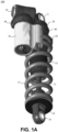
- shock assembly 100 is a coil-over shock assembly, such as, for example, a FOX DHX2 shock assembly with a velocity-sensitive shimmed damping system, one or more coil-over springs 17, a spring preload adjuster 18, and a fluid reservoir 25.
- a coil-over shock assembly such as, for example, a FOX DHX2 shock assembly with a velocity-sensitive shimmed damping system, one or more coil-over springs 17, a spring preload adjuster 18, and a fluid reservoir 25.
- coil-over spring 17 provides an expansive (e.g., spring) force on the shock assembly 100.
- shock assembly 100 includes a piston assembly coupled with the shaft 11, where the piston is located somewhere within the main chamber of body 12. In one embodiment, when installed, the resting sag length of the mounted shock assembly 100 is maintained in compression by the weight of the body it is suspending (e.g., the sprung portion of the vehicle), and in expansion by the "spring" force produced by the expansion component (e.g., coil-over spring 17).
- the shock assembly 100 is described as coil-over style shock assembly.
- the shock assembly 100 is a FOX load optimizing air technology (FLOAT) air shock assembly.
- FLOAT FOX load optimizing air technology
- an air shock assembly is a highperformance shock assembly that use air as springs, instead of heavy steel coil springs or expensive titanium coil springs.
- the shock assembly 100 may be another type of shock assembly such as, but not limited to, a stand-alone fluid damper assembly, an air sprung fluid damper assembly, a twin-tube shock assembly, or the like.
- fluid reservoir 25 is a remote fluid reservoir.
- shock assembly 100 includes attachment features such as, in one embodiment, a chassis mount (e.g., upper eyelet 5) and a frame mount (e.g., lower eyelet 10) which allow shock assembly 100 to be coupled between the unsprung portion of the suspension (e.g., the components of the suspension affected by, or in contact with, the terrain) and the sprung portion.
- a chassis mount e.g., upper eyelet 5
- a frame mount e.g., lower eyelet 10
- shock assembly 100 includes body 12, a body cap 20, and a fluid reservoir 25 fluidly coupled with the body 12.
- shock assembly 100 optionally includes one or more of a manually adjustable high speed and/or low speed compression adjuster 35 and/or a manually adjustable high speed rebound adjuster 16 and/or low speed rebound adjuster 36.
- second fluid circuit adjustments are useful to control shock performance during bigger hits, landings, and square-edged bumps
- first fluid circuit adjustments or low-speed compression (LSC) adjustment
- LSR Low-speed rebound
- HSR high-speed rebound
- HSR high-speed rebound
- the first fluid circuit is utilized as part of the sag setup of the vehicle. Once the first fluid circuit is set, it is usually not necessary to adjust the first fluid circuit during a ride. However, there are times when being able to close and/or adjust a flow of the first fluid circuit is valuable. For example, during a bouncing part of a ride (e.g., rider standing up and pedaling, vehicle traversing rolling bumpy terrain, whoops, etc.) the first fluid circuit can allow some of the force being provided to the drive wheel(s) to be deleteriously dissipated by the shock assembly.
- a bouncing part of a ride e.g., rider standing up and pedaling, vehicle traversing rolling bumpy terrain, whoops, etc.
- the first fluid circuit can allow some of the force being provided to the drive wheel(s) to be deleteriously dissipated by the shock assembly.
- lever 15 is a 2-position lever.
- lever 15 is used to make on-the-fly adjustments to control shock performance, and is able to be adjusted throughout the ride.
- the positions are "open” and "firm”. The open position does not affect the HSC/LSC, preset high- and low-speed compression settings.
- the shock assembly 100 is basically in lockout such that it will have very firm low-speed compression setting, e.g., useful for riding elements like climbing and sprinting.
- the shock assembly can absorb some of the energy provided to the pedals resulting in what is known as pedal bob.
- the pedal bob will cause the vehicle to be heavier and lighter with respect to the ground as the rider pedals (e.g., the shock assembly will compress and rebound through the pedal bob). As the shock assembly compresses and rebounds, and the force of the drive wheel against the terrain similarly changes.
- the characteristics of the shock assembly dominated by the first fluid circuit will basically be locked out. That is, the shock assembly will reduce or stop, for example, fluid flow through the first fluid circuit and, in so doing, reduce or remove the changes in force pushing the drive wheel into the terrain. As such, the vehicle will have reduced or no wheel spin and the rider better able to lay down consistent power with slowed pedal downstroke movement resulting in better drive efficiency.
- the first fluid circuit is then returned to its pre-adjusted first fluid circuit ride setting with the second fluid circuit adjusted out of firm position, in one embodiment.
- shock assembly 100 instead of (or in addition to lever 15), shock assembly 100 includes at least one live valve poppet assembly 80 to electronically perform the position change e.g., open or firm instead of using the manual lever 15.
- the live valve poppet assembly 80 is able to provide additional levels of modification by adjusting the amount of the fluid flow path the valve opens (or closes).
- the at least one live valve poppet assembly 80 is a compression valve.
- the at least one live valve poppet assembly 80 is a base valve, rebound valve, a combination of valve types, and the like.
- the live valve poppet assembly 80 by utilizing the live valve poppet assembly 80 to electronically perform the position change e.g., open or firm instead of using the manual lever 15, the change can be enacted by a remote switch, wirelessly, and even automatically based on sensor input, or the like.
- control switch is offset (such as located on the handlebars, steering wheel, frame, dash, or the like, the user could locate the control switch in a personalized location and use the remote switch to change the open or firm setting.
- the live valve poppet assembly 80 could be in communication with a sensor, mobile device, or the like, that will provide input when the dropper seatpost is dropped, pedal pressure is increased (such as by a user standing), chain force is increased (such as during uphill or sprint conditions), an incline of a certain degree is identified, etc.
- these sensor thresholds would provide an input that would cause the live valve poppet assembly 80 to automatically perform the position change e.g., open or firm.
- shock assembly 100 is part of a suspension system including one or more electronically actuated components, interactive components, and/or control features such as one or more of: a user interface, active and/or semi-active shock assemblies, a controller, one or more sensor(s), a display, a power source, smart components, and the like.
- the one or more sensor(s) could be used to monitor and/or measure things such as temperature, voltage, current, resistance, noise (such as when a motor is actuated, fluid flow through a flow path, engine knocks, pings, etc.), positions of one or more components of a vehicle, device, or the like (e.g., shock positions, ride height, pitch, yaw, roll, etc.), etc.
- the one or more sensor(s) could be forward looking terrain, vibrations, bump, impact event, angular measurements, and the like.
- one or a plurality of component(s) of the suspension system are also smart component(s).
- the smart component(s) will include connective features that allow them to communicate wired or wirelessly with one or more of the electronically actuated components, interactive components, control features, and/or the like.
- FIG. 1A and 1B are shown in given locations in accordance with one embodiment, in other embodiments, one, some, or all of the components shown in Figures 1A and 1B are inverted, located in other locations, separated into two or more pieces and dispersed, combined into fewer pieces, etc.
- the use of the locations of the components as shown in Figures 1A and 1B are indicative of one embodiment, which is provided for purposes of clarity.
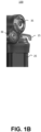
- co-located active valve 200 in an open position is shown in accordance with an embodiment.
- co-located active valve 200 includes vented piston 210, shims 216, control orifice 218, valve ports 220, spool 222, solenoid 240, pilot chambers 244, differential surface 246, and boost valve 248.
- co-located active valve 200 is used to control fluid flow between the main damping chamber (found within body 12) and the external reservoir.
- One path goes through the vented piston 210 and shims 216, which will open at a set pressure threshold.
- the second fluid flow path goes through control orifice 218, valve ports 220, and into the external reservoir 25 through a flow path on another plane (a pre-loaded pressure relief valve).
- valve ports 220 can be blocked by spool 222, which is controlled by solenoid 240.
- solenoid 240 may be an active or semi active valve. In one embodiment, solenoid 240 is manually controlled. In one embodiment, a switch or lever can be used to control solenoid 240 while the vehicle is in use. In one embodiment, a cable is connected between the solenoid 240 and a switch (or the like) to allow solenoid 240 to be controlled from a remote location (e.g., a vehicle cab, bike handlebar, frame, etc.). In one embodiment, solenoid 240 is wirelessly controlled by a controller, mobile device, sensor, or the like.
- spool 222 When in the closed position, spool 222 will block valve ports 220 and fluid will flow through pilot chambers 244 and put pressure on the differential surface 246 of boost valve 248. The additional pressure (or pilot pressure) against the differential surface 246 will cause boost valve 248 to move up and press against shims 216. With this increased pressure, the cracking pressure of shims 216 will increase. This will put shock assembly 100 in a firm damping setting.
- shock assembly 100 When spool 222 is open, shock assembly 100 is in a soft damping setting. That is, opening spool 222 will release the pilot pressure and allow boost valve 248 to move away from shims 216.
- spool 222 has a larger flow capacity than the upstream restrictions (e.g., control orifice 218) allow. As such, without the upstream limit that the control orifice 218 sets, enough fluid would be able to forcefully flow through pilot chambers 244 and prematurely move boost valve 248 to pre-load shims 216. Additionally, saturated flow through valve ports 220 would create a pressure drop which would also act to close boost valve 248.
- upstream restrictions e.g., control orifice 2128
- control orifice is designed with a given diameter to specifically limit the flow to an appropriate level depending on the configuration of the valves in the fluid flow path.
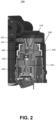
- FIG. 3 a cross-section view of a portion of the shock assembly 100 including the live valve poppet assembly 80 in an open spool state is shown in accordance with an embodiment.
- Figure 4 is a cross-section view of a portion of the shock assembly 100 including the live valve poppet assembly 80 in a closed spool state in accordance with an embodiment.
- Figures 3 and 4 all of the components described in Figure 1A are incorporated by reference in their entirety.
- the cross-sectional views show a portion of a chamber 325 within body cap 20.
- the chamber 325 holding a portion of the working fluid displaced from the damper chamber of body 12.
- Live valve poppet assembly 80 includes a live valve 302 and a poppet 305.
- live valve 302 is located within a housing 303 and poppet 305 is located within chamber 331 of body cap 20.
- poppet 305 has a control orifice 308 therethrough.
- the cross-sectional views also show a reservoir chamber 310 of fluid reservoir 25 that holds the displaced working fluid.
- Flow path 351 traverses between chamber 325 and reservoir chamber 310 via control orifice 308 of the poppet 305 and through the live valve 302.
- flow path 315 is larger than flow path 351 and does not traverse either the poppet 305 or the live valve 302 as it passes through body cap 20 between chamber 325 and reservoir chamber 310.
- live valve 302 may be an active or semi active valve. In one embodiment, live valve 302 is manually controlled. In one embodiment, a switch or lever can be used to control live valve 302 while the shock assembly 100 is in use. In one embodiment, a cable is connected between the live valve 302 and a switch (or the like) to allow live valve 302 to be controlled from a remote location (e.g., a vehicle cab, bike handlebar, frame, etc.). In one embodiment, live valve 302 is wirelessly controlled by a controller, mobile device, sensor, or the like.
- the live valve poppet assembly 80 is in the open state. That is, the spool 352 of the live valve 302 is set to the open position.
- the flow path 351 is open and allows fluid to flow from chamber 325 through control orifice 308 of the poppet 305, along chamber 331 of body cap 20, into the opening of the live valve 302, through the open fluid pathway 344, and into reservoir chamber 310.
- the fluid to flow along flow path 351 there is no pilot pressure on the back side of poppet 305 (e.g., the right side closer to the live valve 302).
- the fluid flowing from chamber 325 will push against the front side of poppet 305 pushing it into its recessed or open position.
- the fluid when in the open position, the fluid will be able to move unencumbered along flow path 315 within the body cap 20 as it moves between chamber 325 and reservoir chamber 310.
- the poppet 305 when in the open position, the poppet 305 will have little or no impact on the damping characteristics of the shock assembly 100.
- the live valve poppet assembly 80 is in the closed state. That is, the spool 352 of the live valve 302 is set to its closed position. When spool 352 is in its closed position, the flow path 351 is closed. As such, fluid will flow from chamber 325 through control orifice 308 of the poppet 305, along chamber 331 of body cap 20, and into the opening of the live valve 302. However, since fluid pathway 344 is blocked by spool 352, the fluid cannot move into reservoir chamber 310. As the fluid is unable to continue its flow, the pilot pressure will build on the back side of poppet 305 (e.g., the right side closer to the live valve 302). In other words, since the pressure area on the backside of poppet 305 is larger than the inlet area (e.g., control orifice 308), the building fluid pressure will push against the back side of poppet 305 pushing it into its closed (or firm) position.
- poppet 305 When poppet 305 is in its closed (or firm) position it will block flow path 315. By blocking flow path 315, the working fluid will not be able to move from chamber 325 and into reservoir chamber 310. Instead, as discussed herein, the compression characteristics of the shock assembly 100 will be in a locked out state as long as the poppet 305 remains in the closed (or firm) position.
- poppet 305 includes a sealing feature 321 such as an O-ring, or the like.
- the sealing feature 321 provides a fluid seal for the poppet 305.
- the sealing feature 321 will provide a loose seal that can allow some amount of fluid to remain on chamber 331 of body cap 20 to allow the fluid to provide lubrication/reduce friction between the sealing feature 321 and body cap 20 to reduce any parasitic friction that occurs with respect to poppet 305 movement.
- a spring 333 is located between the poppet 305 and the surface 345.
- the spring 333 will provide a spring force to overcome the Bernoulli effect and/or any friction in the system, such as friction from sealing feature 321, parasitic friction, or the like, that would stop the poppet 305 from moving to its closed position.
- live valve poppet assembly 80 could provide a varying flow rate through flow path 315.
- poppet 305 would be partially opened or closed to meter the working fluid flow (e.g., control the rate of working fluid flow) to provide a different level of compression damping.
- a wired communication connection (such as via a wiring harness or the like) between one or more electronically actuated components, interactive components, and/or control features of shock assembly 100.
- live valve 302 is coupled with a user interface (and/or controller, sensors, and the like) via a wiring harness.
- power might also be received over the wired connection.
- the motor solenoid, or the like
- the motor that operates live valve 302 would receive its power from a power source coupled with the wiring harness.
- a power source coupled with the wiring harness.
- the vehicle, device, or the like power supply a power supply incorporated with a user interface, a power supply coupled with shock assembly 100, a power supply coupled with another shock assembly (or smart component, etc.), a reserve or extra power supply for auxiliary components, or the like.
- shock assembly 100 there is wireless communication connectivity between the one or more electronically actuated components, interactive components, and/or control features of shock assembly 100.
- live valve 302 is in wireless communication with a user interface (and/or controller, sensors, and the like) without requiring a wiring harness.
- shock assembly 100 would include its own power source and the motor (solenoid, or the like) that operates live valve 302 would receive its operating power therefrom.
- the electronics of shock assembly 100 would be self-contained.
- shock assembly 100 may be in wireless communication with a user interface (and/or controller, sensors, and the like) and inputs received at live valve 302 would be received over the wireless connection.
- the motor solenoid, or the like
- shock assembly 100 would receive its power from a power source via a wiring harness.
- the vehicle, device, or the like power supply a power supply incorporated with a user interface, a power supply coupled with shock assembly 100, a power supply coupled with another shock assembly (or smart component, etc.), a reserve or extra power supply for auxiliary components, or the like.
- the motor solenoid, or the like
- live valve 302 receives its power from its own power source.
- the new and novel live valve poppet assembly 80 configuration allows the offset poppet 305 to close a larger flow area (e.g., flow path 315) instead of only closing the smaller fluid pathway 344 through the live valve 302. As such, the volumetric flow rate from the shaft 11 will be able to move more efficiently into (and out of) reservoir 25.
- the poppet 305 is offset from the spool 352, there is no need for a differential area boost valve element clamping shims against a piston, or the like, to control the opening and or closing of poppet 305 (as used by co-located active valve 200).
- the new and novel live valve poppet assembly 80 will have fewer parts (as there is no boost valve element, shims, etc.), be amicable to different size constraints, and the like.
- control orifice 308 is integrated into the clamping piece, e.g., poppet 305. That means that pressure drop across the control orifice 308 helps to keep the poppet 305 open. The result is close to zero damping when the live valve 302 is open.
Landscapes
- Engineering & Computer Science (AREA)
- General Engineering & Computer Science (AREA)
- Mechanical Engineering (AREA)
- Physics & Mathematics (AREA)
- Fluid Mechanics (AREA)
- Fluid-Damping Devices (AREA)
- Lift Valve (AREA)
Applications Claiming Priority (2)
| Application Number | Priority Date | Filing Date | Title |
|---|---|---|---|
| US202363440783P | 2023-01-24 | 2023-01-24 | |
| US18/420,623 US20240309932A1 (en) | 2023-01-24 | 2024-01-23 | Live valve poppet |
Publications (1)
| Publication Number | Publication Date |
|---|---|
| EP4407208A1 true EP4407208A1 (de) | 2024-07-31 |
Family
ID=89715858
Family Applications (1)
| Application Number | Title | Priority Date | Filing Date |
|---|---|---|---|
| EP24153670.5A Pending EP4407208A1 (de) | 2023-01-24 | 2024-01-24 | Live-ventilanordnung |
Country Status (3)
| Country | Link |
|---|---|
| US (1) | US20240309932A1 (de) |
| EP (1) | EP4407208A1 (de) |
| TW (1) | TW202445035A (de) |
Cited By (1)
| Publication number | Priority date | Publication date | Assignee | Title |
|---|---|---|---|---|
| GB2639080A (en) * | 2023-11-09 | 2025-09-10 | Fox Factory Inc | Valve-controlled fluid circuits |
Citations (13)
| Publication number | Priority date | Publication date | Assignee | Title |
|---|---|---|---|---|
| EP0508466B1 (de) * | 1991-04-12 | 1995-08-30 | Öhlins Racing Ab | Hydraulischer Stossdämpfer |
| US7374028B2 (en) | 2003-07-08 | 2008-05-20 | Fox Factory, Inc. | Damper with pressure-sensitive compression damping |
| US7484603B2 (en) | 2001-08-30 | 2009-02-03 | Fox Factory, Inc. | Shock absorber with electronic control |
| US8838335B2 (en) | 2011-09-12 | 2014-09-16 | Fox Factory, Inc. | Methods and apparatus for suspension set up |
| US8955653B2 (en) | 2009-10-13 | 2015-02-17 | Fox Factory, Incorporated | Methods and apparatus for controlling a fluid damper |
| US9303712B2 (en) | 2008-05-09 | 2016-04-05 | Fox Factory, Inc. | Methods and apparatus for position sensitive suspension damping |
| US10036443B2 (en) | 2009-03-19 | 2018-07-31 | Fox Factory, Inc. | Methods and apparatus for suspension adjustment |
| US10060499B2 (en) | 2009-01-07 | 2018-08-28 | Fox Factory, Inc. | Method and apparatus for an adjustable damper |
| US10443671B2 (en) | 2009-01-07 | 2019-10-15 | Fox Factory, Inc. | Remotely operated bypass for a suspension damper |
| US10576803B2 (en) | 2014-09-17 | 2020-03-03 | Fox Factory, Inc. | Shock absorber |
| US10737546B2 (en) | 2016-04-08 | 2020-08-11 | Fox Factory, Inc. | Electronic compression and rebound control |
| US11162555B2 (en) | 2008-08-25 | 2021-11-02 | Fox Factory, Inc. | Methods and apparatus for suspension lock out and signal generation |
| US20210381574A1 (en) * | 2020-06-05 | 2021-12-09 | Fox Factory, Inc. | Electronic external bypass |
-
2024
- 2024-01-23 US US18/420,623 patent/US20240309932A1/en active Pending
- 2024-01-24 TW TW113102798A patent/TW202445035A/zh unknown
- 2024-01-24 EP EP24153670.5A patent/EP4407208A1/de active Pending
Patent Citations (14)
| Publication number | Priority date | Publication date | Assignee | Title |
|---|---|---|---|---|
| EP0508466B1 (de) * | 1991-04-12 | 1995-08-30 | Öhlins Racing Ab | Hydraulischer Stossdämpfer |
| US7484603B2 (en) | 2001-08-30 | 2009-02-03 | Fox Factory, Inc. | Shock absorber with electronic control |
| US7374028B2 (en) | 2003-07-08 | 2008-05-20 | Fox Factory, Inc. | Damper with pressure-sensitive compression damping |
| US9303712B2 (en) | 2008-05-09 | 2016-04-05 | Fox Factory, Inc. | Methods and apparatus for position sensitive suspension damping |
| US11162555B2 (en) | 2008-08-25 | 2021-11-02 | Fox Factory, Inc. | Methods and apparatus for suspension lock out and signal generation |
| US10060499B2 (en) | 2009-01-07 | 2018-08-28 | Fox Factory, Inc. | Method and apparatus for an adjustable damper |
| US10443671B2 (en) | 2009-01-07 | 2019-10-15 | Fox Factory, Inc. | Remotely operated bypass for a suspension damper |
| US10036443B2 (en) | 2009-03-19 | 2018-07-31 | Fox Factory, Inc. | Methods and apparatus for suspension adjustment |
| US10086670B2 (en) * | 2009-03-19 | 2018-10-02 | Fox Factory, Inc. | Methods and apparatus for suspension set up |
| US8955653B2 (en) | 2009-10-13 | 2015-02-17 | Fox Factory, Incorporated | Methods and apparatus for controlling a fluid damper |
| US8838335B2 (en) | 2011-09-12 | 2014-09-16 | Fox Factory, Inc. | Methods and apparatus for suspension set up |
| US10576803B2 (en) | 2014-09-17 | 2020-03-03 | Fox Factory, Inc. | Shock absorber |
| US10737546B2 (en) | 2016-04-08 | 2020-08-11 | Fox Factory, Inc. | Electronic compression and rebound control |
| US20210381574A1 (en) * | 2020-06-05 | 2021-12-09 | Fox Factory, Inc. | Electronic external bypass |
Cited By (1)
| Publication number | Priority date | Publication date | Assignee | Title |
|---|---|---|---|---|
| GB2639080A (en) * | 2023-11-09 | 2025-09-10 | Fox Factory Inc | Valve-controlled fluid circuits |
Also Published As
| Publication number | Publication date |
|---|---|
| TW202445035A (zh) | 2024-11-16 |
| US20240309932A1 (en) | 2024-09-19 |
Similar Documents
| Publication | Publication Date | Title |
|---|---|---|
| US12496867B2 (en) | Hydraulically-adjustable preload and/or cross-over | |
| US12168379B2 (en) | Shock absorber with a bearing housing bypass assembly | |
| EP2364904B1 (de) | Fahrradluftfederungsanordnung mit einstellbarer Dämpfungsleistung | |
| EP4112969B1 (de) | Einstellbare stossanordnung | |
| US12502923B2 (en) | Hydraulic cross-linked suspension | |
| US12311720B2 (en) | Hydraulic cross-linked suspension | |
| US20230302867A1 (en) | Hydraulic cross-linked suspension | |
| US20130118847A1 (en) | Multi-mode shock assembly | |
| US9056650B2 (en) | Bicycle shock assemblies with plunger operated valve arrangement | |
| EP4253106A1 (de) | Hydraulische vernetzte suspension | |
| EP1234760A2 (de) | Automatische Aufhängungsblockierung für Fahrräder | |
| US20230356558A1 (en) | Shock assembly with by-pass and hydraulic adjust | |
| EP4407208A1 (de) | Live-ventilanordnung | |
| US12409697B2 (en) | Self-pumping spring preload system | |
| US20250129833A1 (en) | Dual piston shock assembly | |
| US20050194197A1 (en) | Wheeled vehicle with suspension units | |
| US20250153801A1 (en) | Valve-controlled fluid circuits | |
| EP4290090A1 (de) | Integrierte lagerhardware für stossanordnung | |
| US20240124092A1 (en) | Variably damped flow control solenoid | |
| EP4040011A1 (de) | Dämpfer mit einem ringförmigen bodenventildurchflusssystem | |
| US20240229892A1 (en) | Tuned mass damper | |
| US20230330792A1 (en) | Spring compressor | |
| WO2008068374A1 (en) | Method and device for the suspension of a motor vehicle |
Legal Events
| Date | Code | Title | Description |
|---|---|---|---|
| PUAI | Public reference made under article 153(3) epc to a published international application that has entered the european phase |
Free format text: ORIGINAL CODE: 0009012 |
|
| STAA | Information on the status of an ep patent application or granted ep patent |
Free format text: STATUS: THE APPLICATION HAS BEEN PUBLISHED |
|
| AK | Designated contracting states |
Kind code of ref document: A1 Designated state(s): AL AT BE BG CH CY CZ DE DK EE ES FI FR GB GR HR HU IE IS IT LI LT LU LV MC ME MK MT NL NO PL PT RO RS SE SI SK SM TR |
|
| STAA | Information on the status of an ep patent application or granted ep patent |
Free format text: STATUS: REQUEST FOR EXAMINATION WAS MADE |
|
| 17P | Request for examination filed |
Effective date: 20250131 |