EP4407201A1 - Bearing unit for rotary shafts - Google Patents
Bearing unit for rotary shafts Download PDFInfo
- Publication number
- EP4407201A1 EP4407201A1 EP24153577.2A EP24153577A EP4407201A1 EP 4407201 A1 EP4407201 A1 EP 4407201A1 EP 24153577 A EP24153577 A EP 24153577A EP 4407201 A1 EP4407201 A1 EP 4407201A1
- Authority
- EP
- European Patent Office
- Prior art keywords
- inner ring
- radially
- radially inner
- bearing unit
- axially
- Prior art date
- Legal status (The legal status is an assumption and is not a legal conclusion. Google has not performed a legal analysis and makes no representation as to the accuracy of the status listed.)
- Granted
Links
Images


Classifications
-
- F—MECHANICAL ENGINEERING; LIGHTING; HEATING; WEAPONS; BLASTING
- F16—ENGINEERING ELEMENTS AND UNITS; GENERAL MEASURES FOR PRODUCING AND MAINTAINING EFFECTIVE FUNCTIONING OF MACHINES OR INSTALLATIONS; THERMAL INSULATION IN GENERAL
- F16C—SHAFTS; FLEXIBLE SHAFTS; ELEMENTS OR CRANKSHAFT MECHANISMS; ROTARY BODIES OTHER THAN GEARING ELEMENTS; BEARINGS
- F16C33/00—Parts of bearings; Special methods for making bearings or parts thereof
- F16C33/72—Sealings
- F16C33/76—Sealings of ball or roller bearings
- F16C33/78—Sealings of ball or roller bearings with a diaphragm, disc, or ring, with or without resilient members
- F16C33/784—Sealings of ball or roller bearings with a diaphragm, disc, or ring, with or without resilient members mounted to a groove in the inner surface of the outer race and extending toward the inner race
- F16C33/7843—Sealings of ball or roller bearings with a diaphragm, disc, or ring, with or without resilient members mounted to a groove in the inner surface of the outer race and extending toward the inner race with a single annular sealing disc
- F16C33/7853—Sealings of ball or roller bearings with a diaphragm, disc, or ring, with or without resilient members mounted to a groove in the inner surface of the outer race and extending toward the inner race with a single annular sealing disc with one or more sealing lips to contact the inner race
-
- F—MECHANICAL ENGINEERING; LIGHTING; HEATING; WEAPONS; BLASTING
- F16—ENGINEERING ELEMENTS AND UNITS; GENERAL MEASURES FOR PRODUCING AND MAINTAINING EFFECTIVE FUNCTIONING OF MACHINES OR INSTALLATIONS; THERMAL INSULATION IN GENERAL
- F16C—SHAFTS; FLEXIBLE SHAFTS; ELEMENTS OR CRANKSHAFT MECHANISMS; ROTARY BODIES OTHER THAN GEARING ELEMENTS; BEARINGS
- F16C19/00—Bearings with rolling contact, for exclusively rotary movement
- F16C19/02—Bearings with rolling contact, for exclusively rotary movement with bearing balls essentially of the same size in one or more circular rows
- F16C19/14—Bearings with rolling contact, for exclusively rotary movement with bearing balls essentially of the same size in one or more circular rows for both radial and axial load
- F16C19/16—Bearings with rolling contact, for exclusively rotary movement with bearing balls essentially of the same size in one or more circular rows for both radial and axial load with a single row of balls
-
- F—MECHANICAL ENGINEERING; LIGHTING; HEATING; WEAPONS; BLASTING
- F16—ENGINEERING ELEMENTS AND UNITS; GENERAL MEASURES FOR PRODUCING AND MAINTAINING EFFECTIVE FUNCTIONING OF MACHINES OR INSTALLATIONS; THERMAL INSULATION IN GENERAL
- F16C—SHAFTS; FLEXIBLE SHAFTS; ELEMENTS OR CRANKSHAFT MECHANISMS; ROTARY BODIES OTHER THAN GEARING ELEMENTS; BEARINGS
- F16C33/00—Parts of bearings; Special methods for making bearings or parts thereof
- F16C33/30—Parts of ball or roller bearings
- F16C33/38—Ball cages
-
- F—MECHANICAL ENGINEERING; LIGHTING; HEATING; WEAPONS; BLASTING
- F16—ENGINEERING ELEMENTS AND UNITS; GENERAL MEASURES FOR PRODUCING AND MAINTAINING EFFECTIVE FUNCTIONING OF MACHINES OR INSTALLATIONS; THERMAL INSULATION IN GENERAL
- F16C—SHAFTS; FLEXIBLE SHAFTS; ELEMENTS OR CRANKSHAFT MECHANISMS; ROTARY BODIES OTHER THAN GEARING ELEMENTS; BEARINGS
- F16C33/00—Parts of bearings; Special methods for making bearings or parts thereof
- F16C33/30—Parts of ball or roller bearings
- F16C33/58—Raceways; Race rings
- F16C33/583—Details of specific parts of races
-
- F—MECHANICAL ENGINEERING; LIGHTING; HEATING; WEAPONS; BLASTING
- F16—ENGINEERING ELEMENTS AND UNITS; GENERAL MEASURES FOR PRODUCING AND MAINTAINING EFFECTIVE FUNCTIONING OF MACHINES OR INSTALLATIONS; THERMAL INSULATION IN GENERAL
- F16C—SHAFTS; FLEXIBLE SHAFTS; ELEMENTS OR CRANKSHAFT MECHANISMS; ROTARY BODIES OTHER THAN GEARING ELEMENTS; BEARINGS
- F16C33/00—Parts of bearings; Special methods for making bearings or parts thereof
- F16C33/72—Sealings
- F16C33/76—Sealings of ball or roller bearings
- F16C33/78—Sealings of ball or roller bearings with a diaphragm, disc, or ring, with or without resilient members
- F16C33/7803—Sealings of ball or roller bearings with a diaphragm, disc, or ring, with or without resilient members suited for particular types of rolling bearings
- F16C33/7806—Sealings of ball or roller bearings with a diaphragm, disc, or ring, with or without resilient members suited for particular types of rolling bearings for spherical roller bearings
-
- F—MECHANICAL ENGINEERING; LIGHTING; HEATING; WEAPONS; BLASTING
- F16—ENGINEERING ELEMENTS AND UNITS; GENERAL MEASURES FOR PRODUCING AND MAINTAINING EFFECTIVE FUNCTIONING OF MACHINES OR INSTALLATIONS; THERMAL INSULATION IN GENERAL
- F16C—SHAFTS; FLEXIBLE SHAFTS; ELEMENTS OR CRANKSHAFT MECHANISMS; ROTARY BODIES OTHER THAN GEARING ELEMENTS; BEARINGS
- F16C33/00—Parts of bearings; Special methods for making bearings or parts thereof
- F16C33/72—Sealings
- F16C33/76—Sealings of ball or roller bearings
- F16C33/78—Sealings of ball or roller bearings with a diaphragm, disc, or ring, with or without resilient members
- F16C33/7816—Details of the sealing or parts thereof, e.g. geometry, material
- F16C33/782—Details of the sealing or parts thereof, e.g. geometry, material of the sealing region
- F16C33/7823—Details of the sealing or parts thereof, e.g. geometry, material of the sealing region of sealing lips
-
- F—MECHANICAL ENGINEERING; LIGHTING; HEATING; WEAPONS; BLASTING
- F16—ENGINEERING ELEMENTS AND UNITS; GENERAL MEASURES FOR PRODUCING AND MAINTAINING EFFECTIVE FUNCTIONING OF MACHINES OR INSTALLATIONS; THERMAL INSULATION IN GENERAL
- F16C—SHAFTS; FLEXIBLE SHAFTS; ELEMENTS OR CRANKSHAFT MECHANISMS; ROTARY BODIES OTHER THAN GEARING ELEMENTS; BEARINGS
- F16C33/00—Parts of bearings; Special methods for making bearings or parts thereof
- F16C33/72—Sealings
- F16C33/76—Sealings of ball or roller bearings
- F16C33/78—Sealings of ball or roller bearings with a diaphragm, disc, or ring, with or without resilient members
- F16C33/7816—Details of the sealing or parts thereof, e.g. geometry, material
- F16C33/782—Details of the sealing or parts thereof, e.g. geometry, material of the sealing region
- F16C33/7826—Details of the sealing or parts thereof, e.g. geometry, material of the sealing region of the opposing surface cooperating with the seal, e.g. a shoulder surface of a bearing ring
-
- F—MECHANICAL ENGINEERING; LIGHTING; HEATING; WEAPONS; BLASTING
- F16—ENGINEERING ELEMENTS AND UNITS; GENERAL MEASURES FOR PRODUCING AND MAINTAINING EFFECTIVE FUNCTIONING OF MACHINES OR INSTALLATIONS; THERMAL INSULATION IN GENERAL
- F16C—SHAFTS; FLEXIBLE SHAFTS; ELEMENTS OR CRANKSHAFT MECHANISMS; ROTARY BODIES OTHER THAN GEARING ELEMENTS; BEARINGS
- F16C33/00—Parts of bearings; Special methods for making bearings or parts thereof
- F16C33/72—Sealings
- F16C33/76—Sealings of ball or roller bearings
- F16C33/78—Sealings of ball or roller bearings with a diaphragm, disc, or ring, with or without resilient members
- F16C33/7869—Sealings of ball or roller bearings with a diaphragm, disc, or ring, with or without resilient members mounted with a cylindrical portion to the inner surface of the outer race and having a radial portion extending inward
- F16C33/7873—Sealings of ball or roller bearings with a diaphragm, disc, or ring, with or without resilient members mounted with a cylindrical portion to the inner surface of the outer race and having a radial portion extending inward with a single sealing ring of generally L-shaped cross-section
- F16C33/7876—Sealings of ball or roller bearings with a diaphragm, disc, or ring, with or without resilient members mounted with a cylindrical portion to the inner surface of the outer race and having a radial portion extending inward with a single sealing ring of generally L-shaped cross-section with sealing lips
Definitions
- the present invention relates to a bearing unit.
- the present invention relates to a bearing unit for supporting one end of a rotary shaft, as specified below, but is generally applicable.
- support assemblies for rotary shafts of a known type comprise a cup-shaped flanged casing, i.e. a casing with a closed bottom, and a bearing unit provided with an outer ring, an inner ring, and a plurality of rolling bodies interposed between the inner ring and the outer ring.
- the outer ring is stationary, while the inner ring is rotary and constrained to rotate with the rotary shaft.
- a sealing device is seated between the outer ring and the inner ring to seal the bearing unit against external contaminants.
- the sealing device is provided with a shaped metal shield interference fitted on the outer ring, which has an elastomer lining.
- the elastomer lining is provided with a pair of contacting lips that make sliding contact with the inner ring to create a seal against external contaminants.
- bearing units do not guarantee an effective seal, in particular in very contaminated environments.
- the most common request received from end users is for a high-performance sealing solution incorporating more than two contacting lips. Such a solution firstly reduces the risk of contamination, and secondly increases frictional resistance during operation, such resistance resulting in greater power losses.
- the present invention is intended to provide a bearing unit for supporting one end of a rotary shaft that does not have the drawbacks described above, i.e. that has a sealing device with good sealing performance and low frictional resistance.
- the present invention provides a bearing unit having the features set out in the attached claims.
- reference sign 1 denotes a bearing unit as a whole, according to a first and preferred embodiment of the present invention.
- the bearing unit 1 can be interposed between a first mechanical element 2 and a second mechanical element 3 of a machine preferably, but not exclusively, comprising a static frame 2 and a rotary shaft 3. Both the static frame and the rotary shaft are known and therefore are shown only schematically in the figure.
- the bearing unit 1 has a central axis X and comprises:
- the sealing device 40 is provided with:
- contacting lips there are more than two contacting lips to ensure excellent sealing performance.
- the contacting lips 43, 44, 45 provide a sliding contact with the radially inner ring 34 caused by radial interference i 0 , i 1 between the corresponding radially inner surfaces S43, S44, S45 of the contacting lips 43, 44, 45 and the radially outer surfaces 34e, 34i of the radially inner ring 34.
- the radial interference i 0 is the interference between corresponding radially inner surfaces S44, S45 of the axially inner lips 44, 45 and the first surface 34i of the radially inner ring 34.
- the value of this radial interference is usually between 0.25 mm and 0.9 mm.
- the interference i 1 is the interference between the radially inner surface S43 of the axially outer lip 43 and the second surface 34e of the radially inner ring 34.
- the radially inner ring 34 has a step 34s so that the first surface 34i is radially more external than the second surface 34e by the radial length "a" of the step 34s. Consequently, the radial interference i 1 of the axially outer lip 43 is less than the radial interference i 0 .
- the difference between the two radial interference values is preferably equal to the radial length "a" of the step 34s.
- a third lip 43 (or further lips in addition to the two axially inner lips 44, 45) coupled with the second surface 34e of the radially outer ring (surface recessed in relation to the first surface 34i) therefore has a negligible effect on the overall frictional resistance of the sealing device, but simultaneously significantly increases sealing performance.
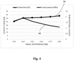
- the foregoing is shown in the graph in Figure 4 , which relates to a finite-element simulation to characterize the sealing device.
- the X-axis of the graph shows the radial interference values in [mm] between the contacting lip and the radially inner ring.
- the two Y-axes show, for the same components, the values of the contact force 50 in [kN] and the values of the contact pressure 60 in [MPa] as the radial interference varies.
- the contact force between the lip and the inner ring decreases as the radial interference decreases, thereby reducing frictional resistance and power loss.
- decreasing radial interference to an interference limit value of approximately 0.45 mm increases the contact pressure between the lip and the inner ring. This is because reducing the radial interference distends the lip, thereby reducing the contact area between the lip and the inner ring, which increases the contact pressure and improves seal performance.
- the lip is substantially distended, and therefore there is no more variation in the contact area between the lip and the inner ring, the area remaining near-constant as the radial interference varies. Consequently, with equal contact areas, the contact pressure follows the trend of the contact force, i.e. lessens as radial interference decreases.
- the radial length of the step 34s may be such as to guarantee a radial interference i 1 between the axially outer lip 43 and the radially inner ring 34 of not less than 0.5 mm.
- the radial interference value is therefore found on the curve 60, which shows that contact pressure increases as radial interference decreases.
- the radial length "a" may be between 0.5 mm and 0.85 mm.
- the axial width of the second surface 34e (i.e. the recessed surface of the radially inner ring) may advantageously be between 4 mm and 6 mm. Values below 4 mm risk the step 34s interfering with the axially outer lip 43, while values greater than 6 mm risk the step 34s interfering with the axially inner lip 44 closest to the axially outer lip 43 (in the example illustrated, the intermediate lip 44).
- the present solution is an optimal trade-off between sealing performance and frictional resistance.
- the described solution provides greater sealing performance, while keeping power losses caused by sliding friction within acceptable limits.
Landscapes
- Engineering & Computer Science (AREA)
- General Engineering & Computer Science (AREA)
- Mechanical Engineering (AREA)
- Sealing With Elastic Sealing Lips (AREA)
- Sealing Of Bearings (AREA)
- Rolling Contact Bearings (AREA)
Abstract
- a stationary radially outer ring (31),
- a rotary radially inner ring (34),
- a sealing device (40), arranged between the radially outer ring (31) and the radially inner ring (34), and in turn comprising:
- a shaped shield (41) mounted stably on the radially outer ring (31), and
- an elastomer lining (42) on the shaped shield (41), which has more than two radial contacting lips (43, 44, 45), in which
- when in use, the contacting lips (43, 44, 45) ensure a sliding contact on a radially outer first surface (34e) and a radially outer second surface (34i) of the radially inner ring (34),
- the radially inner ring (34) has a step (34s) so that:
- the first surface (34i) is radially more external than the second surface (34e) by the radial length (a) of the step (34s), and
- the radial interference (i1) between an axially outer tip (43) and the radially inner ring (34) is smaller than the radial interference (i0) between the axially inner lips (44, 45) and the radially inner ring (34).
Description
- The present invention relates to a bearing unit.
- More specifically, the present invention relates to a bearing unit for supporting one end of a rotary shaft, as specified below, but is generally applicable.
- To support rotary shafts in industrial machinery, support assemblies for rotary shafts of a known type comprise a cup-shaped flanged casing, i.e. a casing with a closed bottom, and a bearing unit provided with an outer ring, an inner ring, and a plurality of rolling bodies interposed between the inner ring and the outer ring. The outer ring is stationary, while the inner ring is rotary and constrained to rotate with the rotary shaft.
- On the side opposite the closed bottom of the outer ring, a sealing device is seated between the outer ring and the inner ring to seal the bearing unit against external contaminants. The sealing device is provided with a shaped metal shield interference fitted on the outer ring, which has an elastomer lining. The elastomer lining is provided with a pair of contacting lips that make sliding contact with the inner ring to create a seal against external contaminants.
- However, such bearing units do not guarantee an effective seal, in particular in very contaminated environments. The most common request received from end users is for a high-performance sealing solution incorporating more than two contacting lips. Such a solution firstly reduces the risk of contamination, and secondly increases frictional resistance during operation, such resistance resulting in greater power losses.
- An acceptable trade-off between minimum frictional resistance and high sealing performance is therefore sought after. However, it is not currently possible to provide a solution with good sealing performance and low frictional resistance (i.e. low power losses) without making a dedicated component for the specific application. Such components thus require customized elements for the mechanical interfaces of the specific application. This inevitably affects standardization and increases the cost of the bearing unit.
- The present invention is intended to provide a bearing unit for supporting one end of a rotary shaft that does not have the drawbacks described above, i.e. that has a sealing device with good sealing performance and low frictional resistance.
- The present invention provides a bearing unit having the features set out in the attached claims.
- The invention is described below with reference to the attached drawings, which show some non-limiting example embodiments of the invention, in which:
-
Figure 1 shows a cross section of a first and preferred embodiment of a bearing unit according to the present invention, -
Figure 2 is a magnified cross-section view of a sealing device of the bearing unit inFigure 1 , -
Figure 3 is a magnified cross-section view of the sealing device inFigure 2 when in use, and -
Figure 4 is a graph showing the features of the sealing device inFigure 2 . - In
Figure 1 ,reference sign 1 denotes a bearing unit as a whole, according to a first and preferred embodiment of the present invention. Thebearing unit 1 can be interposed between a firstmechanical element 2 and a secondmechanical element 3 of a machine preferably, but not exclusively, comprising astatic frame 2 and arotary shaft 3. Both the static frame and the rotary shaft are known and therefore are shown only schematically in the figure. - Throughout the present description and in the claims, terms and expressions indicating positions and orientations, such as "radial" and "axial", are to be understood with reference to the central axis of rotation X of the
bearing unit 1. - The
bearing unit 1 has a central axis X and comprises: - a stationary radially
outer ring 31 provided with a raceway 31'. The radiallyouter ring 31 could in turn comprise a cup-shaped casing 32, i.e. a casing with a closed bottom, that is open at the axially outer end 32' thereof, and aflange 33 transverse to the axis X and rigidly connected to thecasing 32 and stably connected to thestatic frame 2, - a rotary radially
inner ring 34 provided with a raceway 34' and stably connected to therotary shaft 3, - a plurality of
rolling bodies 35, specifically balls, interposed between the radiallyouter ring 31 and the radiallyinner ring 34 to enable relative rotation between the radiallyinner ring 34 and the radiallyouter ring 31, - a
cage 36 for the plurality of rolling bodies, and - a
sealing device 40 arranged between the radiallyouter ring 31 and the radiallyinner ring 34 at the axially outer end 32' of the radiallyouter ring 31. - With reference to
Figure 2 , thesealing device 40 is provided with: - a
shaped shield 41 that is stably mounted on the radiallyouter ring 31 by inserting a radially outer foldededge 41a thereof into a radiallyinner groove 31a of the radially outer ring, - an
elastomer lining 42 arranged on theshaped shield 41 and axially inside said shapedshield 41. The elastomer lining has substantially radial contactinglips first surface 34e and a radially outer second surface 34i of the radiallyinner ring 34. - There are more than two contacting lips to ensure excellent sealing performance. In the preferred solution shown in the attached figures, there are three contacting lips, specifically an axially
outer lip 43, a first axiallyinner lip 44, and a second axiallyinner lip 45. - When in use, the contacting
lips inner ring 34 caused by radial interference i0, i1 between the corresponding radially inner surfaces S43, S44, S45 of the contactinglips outer surfaces 34e, 34i of the radiallyinner ring 34. - In particular, the radial interference i0 is the interference between corresponding radially inner surfaces S44, S45 of the axially
inner lips inner ring 34. The value of this radial interference is usually between 0.25 mm and 0.9 mm. Conversely, the interference i1 is the interference between the radially inner surface S43 of the axiallyouter lip 43 and thesecond surface 34e of the radiallyinner ring 34. - According to the invention, the radially
inner ring 34 has astep 34s so that the first surface 34i is radially more external than thesecond surface 34e by the radial length "a" of thestep 34s. Consequently, the radial interference i1 of the axiallyouter lip 43 is less than the radial interference i0. The difference between the two radial interference values is preferably equal to the radial length "a" of thestep 34s. - Also, with reference to
Figure 3 , this means that the axiallyouter lip 43 is deformed less than the axiallyinner lips outer lip 43 and the radially inner ring 34 (lower compared to the force exchanged between the axiallyinner lips - Furthermore, lesser deformation of the axially
outer lip 43 entails a "distension" of said lip and therefore a contact area A43 between the axiallyouter lip 43 and the radiallyinner ring 34 that is smaller than the corresponding contact areas A44, A45 between the axiallyinner lips inner ring 34, which results in greater contact pressure between the axiallyouter lip 43 and the radiallyinner ring 34 and therefore a better seal. - The addition of a third lip 43 (or further lips in addition to the two axially
inner lips 44, 45) coupled with thesecond surface 34e of the radially outer ring (surface recessed in relation to the first surface 34i) therefore has a negligible effect on the overall frictional resistance of the sealing device, but simultaneously significantly increases sealing performance. - The foregoing is shown in the graph in
Figure 4 , which relates to a finite-element simulation to characterize the sealing device. The X-axis of the graph shows the radial interference values in [mm] between the contacting lip and the radially inner ring. The two Y-axes show, for the same components, the values of thecontact force 50 in [kN] and the values of thecontact pressure 60 in [MPa] as the radial interference varies. - As shown, the contact force between the lip and the inner ring decreases as the radial interference decreases, thereby reducing frictional resistance and power loss. Simultaneously, decreasing radial interference to an interference limit value of approximately 0.45 mm increases the contact pressure between the lip and the inner ring. This is because reducing the radial interference distends the lip, thereby reducing the contact area between the lip and the inner ring, which increases the contact pressure and improves seal performance. For radial interference values below 0.45 mm, the lip is substantially distended, and therefore there is no more variation in the contact area between the lip and the inner ring, the area remaining near-constant as the radial interference varies. Consequently, with equal contact areas, the contact pressure follows the trend of the contact force, i.e. lessens as radial interference decreases.
- Consequently, combining the axially
outer lip 43 with the two axiallyinner lips - Advantageously, the radial length of the
step 34s may be such as to guarantee a radial interference i1 between the axiallyouter lip 43 and the radiallyinner ring 34 of not less than 0.5 mm. The radial interference value is therefore found on thecurve 60, which shows that contact pressure increases as radial interference decreases. - Preferably and depending on the specific application, the radial length "a" may be between 0.5 mm and 0.85 mm.
- The axial width of the
second surface 34e (i.e. the recessed surface of the radially inner ring) may advantageously be between 4 mm and 6 mm. Values below 4 mm risk thestep 34s interfering with the axiallyouter lip 43, while values greater than 6 mm risk thestep 34s interfering with the axiallyinner lip 44 closest to the axially outer lip 43 (in the example illustrated, the intermediate lip 44). - In short, the present solution is an optimal trade-off between sealing performance and frictional resistance. With regard to a sealing device with two contacting lips according to the prior art, the described solution provides greater sealing performance, while keeping power losses caused by sliding friction within acceptable limits.
- Furthermore, the identified solution:
- enables use of a sealing device with three lips (or in any case with more than two lips) without requiring a customized shape for the specific application,
- requires a simple machining of the radially inner ring to create a step with a recessed surface that can be easily coupled with the axially outer lip,
- the step formed on the radially inner ring confers the described advantages: low contact force but high contact pressure between the lip and the ring,
- the step formed on the radially inner ring does not adversely affect the mechanical strength of the ring since it is remote from the most stressed zone, which is the raceway,
- in any case, the step represents a reduction in material, making the radially inner ring more lightweight.
- In addition to the embodiments described above, numerous other variants of the invention are possible. Such embodiments should be understood to be examples and do not limit the scope, applications or possible configurations of the invention. Indeed, although the description provided above enables the person skilled in the art to carry out the present invention at least according to one example configuration thereof, numerous variations of the components described could be used without thereby moving outside the scope of the invention, as defined in the attached claims, interpreted literally and/or according to their legal equivalents.
Claims (8)
- Bearing unit (1) having a central axis (X) and provided with:- a radially outer ring (31), stationary,- a radially inner ring (34), rotatable,- a sealing device (40), arranged between the radially outer ring (31) and the radially inner ring (34), and in turn comprising:- a shaped shield (41) which is mounted stably on the radially outer ring (31), e- an elastomer lining (42), supported by the shaped shield (41), which has contacting lips (43, 44, 45), radial and more than two in number, the bearing unit (1) being characterized by the fact that, in combination:- the contacting lips (43, 44, 45) ensure in use a sliding contact on a first surface (34e) and on a second surface (34i) of the radially internal ring (34), both radially external,- the radially inner ring (34) has a step (34s) so that:- the first surface (34i) is radially more external than the second surface (34e) by the radial length (a) of the step (34s), and- a radial interference (i1) between an axially outer lip (43) and the radially inner ring (34) is smaller than a radial interference (i0) between axially inner lips (44, 45) and the radially inner ring (34).
- Bearing unit according to claim 1, wherein the radial interference (i1) is smaller than the radial interference (i0) by the radial length (a) of the step (34s).
- Bearing unit according to claim 2, wherein the number of contacting lips (43, 44, 45) is equal to three and the contacting lips comprise the axially outer lip (43), a first axially inner lip (44) and a second axially inner lip (45).
- Bearing unit according to one of the preceding claims, wherein the radial interference i0 is defined between corresponding radially inner surfaces (S44, S45) of the axially inner lips (44, 45) and the first surface (34i) of the radially inner ring (34) and the interference (i1) is defined between a radially inner surface (S43) of the axially outer lip (43) and the second surface (34e) of the radially inner ring (34).
- Bearing unit according to any of the preceding claims, wherein a contact area (A43) between the axially outer lip (43) and the radially inner ring (34) is smaller than the corresponding contact areas (A44, A45) between the axially inner lips (44, 45) and the radially inner ring (34).
- Bearing unit according to any of the preceding claims, wherein the radial length (a) of the step (34s) is such that the radial interference (i1) between the axially outer lip (43) and the radially inner ring (34) is not less than 0.5 mm.
- Bearing unit according to any of the preceding claims, wherein the radial length (a) is between 0.5 mm and 0.85 mm.
- Bearing unit according to any of claims from 3 to 7, wherein an axial width of the second surface (34e) of the radially inner ring (34) is between 4 mm and 6 mm.
Applications Claiming Priority (1)
| Application Number | Priority Date | Filing Date | Title |
|---|---|---|---|
| IT102023000001266A IT202300001266A1 (en) | 2023-01-27 | 2023-01-27 | BEARING UNIT FOR ROTARY SHAFT |
Publications (2)
| Publication Number | Publication Date |
|---|---|
| EP4407201A1 true EP4407201A1 (en) | 2024-07-31 |
| EP4407201B1 EP4407201B1 (en) | 2025-05-14 |
Family
ID=86007006
Family Applications (1)
| Application Number | Title | Priority Date | Filing Date |
|---|---|---|---|
| EP24153577.2A Active EP4407201B1 (en) | 2023-01-27 | 2024-01-24 | Bearing unit for rotary shafts |
Country Status (5)
| Country | Link |
|---|---|
| US (1) | US12460678B2 (en) |
| EP (1) | EP4407201B1 (en) |
| CN (1) | CN118407971A (en) |
| DK (1) | DK4407201T3 (en) |
| IT (1) | IT202300001266A1 (en) |
Citations (3)
| Publication number | Priority date | Publication date | Assignee | Title |
|---|---|---|---|---|
| FR2249573A5 (en) * | 1973-10-29 | 1975-05-23 | Skf Cie Applic Mecanique | Seal for rolling bearing - has triple sealing lips combined with labyrinth seal to exclude fibrous foreign matter |
| CN101265949A (en) * | 2008-04-23 | 2008-09-17 | 陆连运 | Three lips contact type seal bearing |
| WO2010136058A1 (en) * | 2009-05-25 | 2010-12-02 | Aktiebolaget Skf | A bearing seal assembly, particularly for use in agricultural applications |
Family Cites Families (5)
| Publication number | Priority date | Publication date | Assignee | Title |
|---|---|---|---|---|
| CA2179554A1 (en) * | 1995-06-21 | 1996-12-22 | Daniel R. Mclarty | Inner ring design for ball and roller bearings |
| JP3940304B2 (en) * | 2002-03-07 | 2007-07-04 | 株式会社山田製作所 | Water pump bearing seal device |
| JP5288305B2 (en) * | 2008-02-05 | 2013-09-11 | Ntn株式会社 | Rubber seal fixing device for rolling bearing sealing |
| US8641289B2 (en) * | 2011-01-05 | 2014-02-04 | Charles Winfield Scott | Triple-lip seals for bearings and bearings incorporating the same |
| KR102667609B1 (en) * | 2019-11-11 | 2024-05-22 | 주식회사 일진글로벌 | Bearing device having improved sealing mounting structure |
-
2023
- 2023-01-27 IT IT102023000001266A patent/IT202300001266A1/en unknown
- 2023-11-21 US US18/515,383 patent/US12460678B2/en active Active
-
2024
- 2024-01-22 CN CN202410086126.9A patent/CN118407971A/en active Pending
- 2024-01-24 DK DK24153577.2T patent/DK4407201T3/en active
- 2024-01-24 EP EP24153577.2A patent/EP4407201B1/en active Active
Patent Citations (3)
| Publication number | Priority date | Publication date | Assignee | Title |
|---|---|---|---|---|
| FR2249573A5 (en) * | 1973-10-29 | 1975-05-23 | Skf Cie Applic Mecanique | Seal for rolling bearing - has triple sealing lips combined with labyrinth seal to exclude fibrous foreign matter |
| CN101265949A (en) * | 2008-04-23 | 2008-09-17 | 陆连运 | Three lips contact type seal bearing |
| WO2010136058A1 (en) * | 2009-05-25 | 2010-12-02 | Aktiebolaget Skf | A bearing seal assembly, particularly for use in agricultural applications |
Also Published As
| Publication number | Publication date |
|---|---|
| EP4407201B1 (en) | 2025-05-14 |
| US12460678B2 (en) | 2025-11-04 |
| US20240255029A1 (en) | 2024-08-01 |
| DK4407201T3 (en) | 2025-08-18 |
| IT202300001266A1 (en) | 2024-07-27 |
| CN118407971A (en) | 2024-07-30 |
Similar Documents
| Publication | Publication Date | Title |
|---|---|---|
| EP2469110B1 (en) | Sealing device and rolling bearing device provided with sealing device | |
| US6921083B2 (en) | Sealing apparatus and a rolling bearing and a clutch apparatus provided therewith | |
| JP5417481B2 (en) | Gear transmission | |
| JP2960040B2 (en) | Sealing device | |
| JP2006266451A (en) | Rolling bearing with sealing device | |
| EP4407201B1 (en) | Bearing unit for rotary shafts | |
| JP2006336734A (en) | Rolling bearing with sealing device | |
| EP1170519B1 (en) | Compound bearing apparatus | |
| KR102433047B1 (en) | Sealing structure | |
| EP3611406B1 (en) | Sealing device | |
| JPH0429130Y2 (en) | ||
| JP2009074589A (en) | Sealing device | |
| JP4735453B2 (en) | Rolling bearing device | |
| JP4893550B2 (en) | Sealing device | |
| US8202006B2 (en) | Sealing device, rolling bearing, and rolling bearing for wheel | |
| JP2000120711A (en) | Rolling bearing | |
| JP2020176673A (en) | Seal structure and seal | |
| CN113646551B (en) | Rolling bearings | |
| JP2000249149A (en) | Ball bearing unit | |
| JP5625539B2 (en) | Sealed rolling bearing | |
| JP2006161876A (en) | Rolling bearing | |
| JP2013036493A (en) | Rolling bearing | |
| JP2004183827A (en) | Sealing device for rolling bearing | |
| JP2006214533A (en) | Thrust cylindrical roller bearing | |
| JP2007010034A (en) | Two-row combination bearing and support unit |
Legal Events
| Date | Code | Title | Description |
|---|---|---|---|
| PUAI | Public reference made under article 153(3) epc to a published international application that has entered the european phase |
Free format text: ORIGINAL CODE: 0009012 |
|
| STAA | Information on the status of an ep patent application or granted ep patent |
Free format text: STATUS: THE APPLICATION HAS BEEN PUBLISHED |
|
| AK | Designated contracting states |
Kind code of ref document: A1 Designated state(s): AL AT BE BG CH CY CZ DE DK EE ES FI FR GB GR HR HU IE IS IT LI LT LU LV MC ME MK MT NL NO PL PT RO RS SE SI SK SM TR |
|
| STAA | Information on the status of an ep patent application or granted ep patent |
Free format text: STATUS: REQUEST FOR EXAMINATION WAS MADE |
|
| 17P | Request for examination filed |
Effective date: 20250113 |
|
| GRAP | Despatch of communication of intention to grant a patent |
Free format text: ORIGINAL CODE: EPIDOSNIGR1 |
|
| STAA | Information on the status of an ep patent application or granted ep patent |
Free format text: STATUS: GRANT OF PATENT IS INTENDED |
|
| INTG | Intention to grant announced |
Effective date: 20250220 |
|
| GRAS | Grant fee paid |
Free format text: ORIGINAL CODE: EPIDOSNIGR3 |
|
| GRAA | (expected) grant |
Free format text: ORIGINAL CODE: 0009210 |
|
| STAA | Information on the status of an ep patent application or granted ep patent |
Free format text: STATUS: THE PATENT HAS BEEN GRANTED |
|
| AK | Designated contracting states |
Kind code of ref document: B1 Designated state(s): AL AT BE BG CH CY CZ DE DK EE ES FI FR GB GR HR HU IE IS IT LI LT LU LV MC ME MK MT NL NO PL PT RO RS SE SI SK SM TR |
|
| REG | Reference to a national code |
Ref country code: GB Ref legal event code: FG4D |
|
| REG | Reference to a national code |
Ref country code: CH Ref legal event code: EP |
|
| P01 | Opt-out of the competence of the unified patent court (upc) registered |
Free format text: CASE NUMBER: APP_17579/2025 Effective date: 20250410 |
|
| REG | Reference to a national code |
Ref country code: DE Ref legal event code: R096 Ref document number: 602024000118 Country of ref document: DE |
|
| REG | Reference to a national code |
Ref country code: IE Ref legal event code: FG4D |
|
| REG | Reference to a national code |
Ref country code: NL Ref legal event code: FP |
|
| REG | Reference to a national code |
Ref country code: DK Ref legal event code: T3 Effective date: 20250806 |
|
| PG25 | Lapsed in a contracting state [announced via postgrant information from national office to epo] |
Ref country code: ES Free format text: LAPSE BECAUSE OF FAILURE TO SUBMIT A TRANSLATION OF THE DESCRIPTION OR TO PAY THE FEE WITHIN THE PRESCRIBED TIME-LIMIT Effective date: 20250514 Ref country code: PT Free format text: LAPSE BECAUSE OF FAILURE TO SUBMIT A TRANSLATION OF THE DESCRIPTION OR TO PAY THE FEE WITHIN THE PRESCRIBED TIME-LIMIT Effective date: 20250915 Ref country code: FI Free format text: LAPSE BECAUSE OF FAILURE TO SUBMIT A TRANSLATION OF THE DESCRIPTION OR TO PAY THE FEE WITHIN THE PRESCRIBED TIME-LIMIT Effective date: 20250514 |
|
| REG | Reference to a national code |
Ref country code: LT Ref legal event code: MG9D |
|
| PG25 | Lapsed in a contracting state [announced via postgrant information from national office to epo] |
Ref country code: NO Free format text: LAPSE BECAUSE OF FAILURE TO SUBMIT A TRANSLATION OF THE DESCRIPTION OR TO PAY THE FEE WITHIN THE PRESCRIBED TIME-LIMIT Effective date: 20250814 Ref country code: GR Free format text: LAPSE BECAUSE OF FAILURE TO SUBMIT A TRANSLATION OF THE DESCRIPTION OR TO PAY THE FEE WITHIN THE PRESCRIBED TIME-LIMIT Effective date: 20250815 |
|
| PG25 | Lapsed in a contracting state [announced via postgrant information from national office to epo] |
Ref country code: PL Free format text: LAPSE BECAUSE OF FAILURE TO SUBMIT A TRANSLATION OF THE DESCRIPTION OR TO PAY THE FEE WITHIN THE PRESCRIBED TIME-LIMIT Effective date: 20250514 |
|
| REG | Reference to a national code |
Ref country code: AT Ref legal event code: MK05 Ref document number: 1794991 Country of ref document: AT Kind code of ref document: T Effective date: 20250514 |
|
| PG25 | Lapsed in a contracting state [announced via postgrant information from national office to epo] |
Ref country code: BG Free format text: LAPSE BECAUSE OF FAILURE TO SUBMIT A TRANSLATION OF THE DESCRIPTION OR TO PAY THE FEE WITHIN THE PRESCRIBED TIME-LIMIT Effective date: 20250514 |
|
| PG25 | Lapsed in a contracting state [announced via postgrant information from national office to epo] |
Ref country code: HR Free format text: LAPSE BECAUSE OF FAILURE TO SUBMIT A TRANSLATION OF THE DESCRIPTION OR TO PAY THE FEE WITHIN THE PRESCRIBED TIME-LIMIT Effective date: 20250514 |
|
| PG25 | Lapsed in a contracting state [announced via postgrant information from national office to epo] |
Ref country code: AT Free format text: LAPSE BECAUSE OF FAILURE TO SUBMIT A TRANSLATION OF THE DESCRIPTION OR TO PAY THE FEE WITHIN THE PRESCRIBED TIME-LIMIT Effective date: 20250514 |
|
| PG25 | Lapsed in a contracting state [announced via postgrant information from national office to epo] |
Ref country code: RS Free format text: LAPSE BECAUSE OF FAILURE TO SUBMIT A TRANSLATION OF THE DESCRIPTION OR TO PAY THE FEE WITHIN THE PRESCRIBED TIME-LIMIT Effective date: 20250814 |
|
| PG25 | Lapsed in a contracting state [announced via postgrant information from national office to epo] |
Ref country code: IS Free format text: LAPSE BECAUSE OF FAILURE TO SUBMIT A TRANSLATION OF THE DESCRIPTION OR TO PAY THE FEE WITHIN THE PRESCRIBED TIME-LIMIT Effective date: 20250914 |
|
| PG25 | Lapsed in a contracting state [announced via postgrant information from national office to epo] |
Ref country code: LV Free format text: LAPSE BECAUSE OF FAILURE TO SUBMIT A TRANSLATION OF THE DESCRIPTION OR TO PAY THE FEE WITHIN THE PRESCRIBED TIME-LIMIT Effective date: 20250514 |
|
| PG25 | Lapsed in a contracting state [announced via postgrant information from national office to epo] |
Ref country code: SM Free format text: LAPSE BECAUSE OF FAILURE TO SUBMIT A TRANSLATION OF THE DESCRIPTION OR TO PAY THE FEE WITHIN THE PRESCRIBED TIME-LIMIT Effective date: 20250514 |
|
| PG25 | Lapsed in a contracting state [announced via postgrant information from national office to epo] |
Ref country code: CZ Free format text: LAPSE BECAUSE OF FAILURE TO SUBMIT A TRANSLATION OF THE DESCRIPTION OR TO PAY THE FEE WITHIN THE PRESCRIBED TIME-LIMIT Effective date: 20250514 |
|
| PG25 | Lapsed in a contracting state [announced via postgrant information from national office to epo] |
Ref country code: EE Free format text: LAPSE BECAUSE OF FAILURE TO SUBMIT A TRANSLATION OF THE DESCRIPTION OR TO PAY THE FEE WITHIN THE PRESCRIBED TIME-LIMIT Effective date: 20250514 |
|
| PG25 | Lapsed in a contracting state [announced via postgrant information from national office to epo] |
Ref country code: SK Free format text: LAPSE BECAUSE OF FAILURE TO SUBMIT A TRANSLATION OF THE DESCRIPTION OR TO PAY THE FEE WITHIN THE PRESCRIBED TIME-LIMIT Effective date: 20250514 |
|
| REG | Reference to a national code |
Ref country code: DE Ref legal event code: R097 Ref document number: 602024000118 Country of ref document: DE |
|
| PLBE | No opposition filed within time limit |
Free format text: ORIGINAL CODE: 0009261 |
|
| STAA | Information on the status of an ep patent application or granted ep patent |
Free format text: STATUS: NO OPPOSITION FILED WITHIN TIME LIMIT |
|
| REG | Reference to a national code |
Ref country code: CH Ref legal event code: L10 Free format text: ST27 STATUS EVENT CODE: U-0-0-L10-L00 (AS PROVIDED BY THE NATIONAL OFFICE) Effective date: 20260325 |
|
| PGFP | Annual fee paid to national office [announced via postgrant information from national office to epo] |
Ref country code: DK Payment date: 20260123 Year of fee payment: 3 Ref country code: DE Payment date: 20260127 Year of fee payment: 3 |
|
| PGFP | Annual fee paid to national office [announced via postgrant information from national office to epo] |
Ref country code: BE Payment date: 20260123 Year of fee payment: 3 Ref country code: IT Payment date: 20260131 Year of fee payment: 3 |
|
| PGFP | Annual fee paid to national office [announced via postgrant information from national office to epo] |
Ref country code: FR Payment date: 20260126 Year of fee payment: 3 |
|
| 26N | No opposition filed |
Effective date: 20260217 |
|
| PG25 | Lapsed in a contracting state [announced via postgrant information from national office to epo] |
Ref country code: LT Free format text: LAPSE BECAUSE OF FAILURE TO SUBMIT A TRANSLATION OF THE DESCRIPTION OR TO PAY THE FEE WITHIN THE PRESCRIBED TIME-LIMIT Effective date: 20250514 |
|
| PG25 | Lapsed in a contracting state [announced via postgrant information from national office to epo] |
Ref country code: SE Free format text: LAPSE BECAUSE OF FAILURE TO SUBMIT A TRANSLATION OF THE DESCRIPTION OR TO PAY THE FEE WITHIN THE PRESCRIBED TIME-LIMIT Effective date: 20250514 |