EP4407193A1 - Fluid circuit - Google Patents
Fluid circuit Download PDFInfo
- Publication number
- EP4407193A1 EP4407193A1 EP22872798.8A EP22872798A EP4407193A1 EP 4407193 A1 EP4407193 A1 EP 4407193A1 EP 22872798 A EP22872798 A EP 22872798A EP 4407193 A1 EP4407193 A1 EP 4407193A1
- Authority
- EP
- European Patent Office
- Prior art keywords
- pressure
- increasing
- piston
- pilot
- oil passage
- Prior art date
- Legal status (The legal status is an assumption and is not a legal conclusion. Google has not performed a legal analysis and makes no representation as to the accuracy of the status listed.)
- Pending
Links
Images








Classifications
-
- F—MECHANICAL ENGINEERING; LIGHTING; HEATING; WEAPONS; BLASTING
- F15—FLUID-PRESSURE ACTUATORS; HYDRAULICS OR PNEUMATICS IN GENERAL
- F15B—SYSTEMS ACTING BY MEANS OF FLUIDS IN GENERAL; FLUID-PRESSURE ACTUATORS, e.g. SERVOMOTORS; DETAILS OF FLUID-PRESSURE SYSTEMS, NOT OTHERWISE PROVIDED FOR
- F15B3/00—Intensifiers or fluid-pressure converters, e.g. pressure exchangers; Conveying pressure from one fluid system to another, without contact between the fluids
-
- F—MECHANICAL ENGINEERING; LIGHTING; HEATING; WEAPONS; BLASTING
- F04—POSITIVE - DISPLACEMENT MACHINES FOR LIQUIDS; PUMPS FOR LIQUIDS OR ELASTIC FLUIDS
- F04B—POSITIVE-DISPLACEMENT MACHINES FOR LIQUIDS; PUMPS
- F04B9/00—Piston machines or pumps characterised by the driving or driven means to or from their working members
- F04B9/08—Piston machines or pumps characterised by the driving or driven means to or from their working members the means being fluid
- F04B9/10—Piston machines or pumps characterised by the driving or driven means to or from their working members the means being fluid the fluid being liquid
- F04B9/103—Piston machines or pumps characterised by the driving or driven means to or from their working members the means being fluid the fluid being liquid having only one pumping chamber
- F04B9/107—Piston machines or pumps characterised by the driving or driven means to or from their working members the means being fluid the fluid being liquid having only one pumping chamber rectilinear movement of the pumping member in the working direction being obtained by a single-acting liquid motor, e.g. actuated in the other direction by gravity or a spring
- F04B9/1076—Piston machines or pumps characterised by the driving or driven means to or from their working members the means being fluid the fluid being liquid having only one pumping chamber rectilinear movement of the pumping member in the working direction being obtained by a single-acting liquid motor, e.g. actuated in the other direction by gravity or a spring with fluid-actuated inlet or outlet valve
-
- F—MECHANICAL ENGINEERING; LIGHTING; HEATING; WEAPONS; BLASTING
- F15—FLUID-PRESSURE ACTUATORS; HYDRAULICS OR PNEUMATICS IN GENERAL
- F15B—SYSTEMS ACTING BY MEANS OF FLUIDS IN GENERAL; FLUID-PRESSURE ACTUATORS, e.g. SERVOMOTORS; DETAILS OF FLUID-PRESSURE SYSTEMS, NOT OTHERWISE PROVIDED FOR
- F15B1/00—Installations or systems with accumulators; Supply reservoir or sump assemblies
- F15B1/02—Installations or systems with accumulators
- F15B1/024—Installations or systems with accumulators used as a supplementary power source, e.g. to store energy in idle periods to balance pump load
-
- F—MECHANICAL ENGINEERING; LIGHTING; HEATING; WEAPONS; BLASTING
- F15—FLUID-PRESSURE ACTUATORS; HYDRAULICS OR PNEUMATICS IN GENERAL
- F15B—SYSTEMS ACTING BY MEANS OF FLUIDS IN GENERAL; FLUID-PRESSURE ACTUATORS, e.g. SERVOMOTORS; DETAILS OF FLUID-PRESSURE SYSTEMS, NOT OTHERWISE PROVIDED FOR
- F15B1/00—Installations or systems with accumulators; Supply reservoir or sump assemblies
- F15B1/02—Installations or systems with accumulators
- F15B1/027—Installations or systems with accumulators having accumulator charging devices
-
- F—MECHANICAL ENGINEERING; LIGHTING; HEATING; WEAPONS; BLASTING
- F15—FLUID-PRESSURE ACTUATORS; HYDRAULICS OR PNEUMATICS IN GENERAL
- F15B—SYSTEMS ACTING BY MEANS OF FLUIDS IN GENERAL; FLUID-PRESSURE ACTUATORS, e.g. SERVOMOTORS; DETAILS OF FLUID-PRESSURE SYSTEMS, NOT OTHERWISE PROVIDED FOR
- F15B11/00—Servomotor systems without provision for follow-up action; Circuits therefor
- F15B11/02—Systems essentially incorporating special features for controlling the speed or actuating force of an output member
- F15B11/028—Systems essentially incorporating special features for controlling the speed or actuating force of an output member for controlling the actuating force
- F15B11/032—Systems essentially incorporating special features for controlling the speed or actuating force of an output member for controlling the actuating force by means of fluid-pressure converters
-
- F—MECHANICAL ENGINEERING; LIGHTING; HEATING; WEAPONS; BLASTING
- F15—FLUID-PRESSURE ACTUATORS; HYDRAULICS OR PNEUMATICS IN GENERAL
- F15B—SYSTEMS ACTING BY MEANS OF FLUIDS IN GENERAL; FLUID-PRESSURE ACTUATORS, e.g. SERVOMOTORS; DETAILS OF FLUID-PRESSURE SYSTEMS, NOT OTHERWISE PROVIDED FOR
- F15B13/00—Details of servomotor systems ; Valves for servomotor systems
- F15B13/02—Fluid distribution or supply devices characterised by their adaptation to the control of servomotors
- F15B13/04—Fluid distribution or supply devices characterised by their adaptation to the control of servomotors for use with a single servomotor
- F15B13/042—Fluid distribution or supply devices characterised by their adaptation to the control of servomotors for use with a single servomotor operated by fluid pressure
- F15B13/0422—Fluid distribution or supply devices characterised by their adaptation to the control of servomotors for use with a single servomotor operated by fluid pressure with manually-operated pilot valves, e.g. joysticks
- F15B13/0424—Fluid distribution or supply devices characterised by their adaptation to the control of servomotors for use with a single servomotor operated by fluid pressure with manually-operated pilot valves, e.g. joysticks the joysticks being provided with electrical switches or sensors
-
- F—MECHANICAL ENGINEERING; LIGHTING; HEATING; WEAPONS; BLASTING
- F15—FLUID-PRESSURE ACTUATORS; HYDRAULICS OR PNEUMATICS IN GENERAL
- F15B—SYSTEMS ACTING BY MEANS OF FLUIDS IN GENERAL; FLUID-PRESSURE ACTUATORS, e.g. SERVOMOTORS; DETAILS OF FLUID-PRESSURE SYSTEMS, NOT OTHERWISE PROVIDED FOR
- F15B2211/00—Circuits for servomotor systems
- F15B2211/20—Fluid pressure source, e.g. accumulator or variable axial piston pump
- F15B2211/205—Systems with pumps
- F15B2211/2053—Type of pump
- F15B2211/20546—Type of pump variable capacity
-
- F—MECHANICAL ENGINEERING; LIGHTING; HEATING; WEAPONS; BLASTING
- F15—FLUID-PRESSURE ACTUATORS; HYDRAULICS OR PNEUMATICS IN GENERAL
- F15B—SYSTEMS ACTING BY MEANS OF FLUIDS IN GENERAL; FLUID-PRESSURE ACTUATORS, e.g. SERVOMOTORS; DETAILS OF FLUID-PRESSURE SYSTEMS, NOT OTHERWISE PROVIDED FOR
- F15B2211/00—Circuits for servomotor systems
- F15B2211/20—Fluid pressure source, e.g. accumulator or variable axial piston pump
- F15B2211/205—Systems with pumps
- F15B2211/20576—Systems with pumps with multiple pumps
-
- F—MECHANICAL ENGINEERING; LIGHTING; HEATING; WEAPONS; BLASTING
- F15—FLUID-PRESSURE ACTUATORS; HYDRAULICS OR PNEUMATICS IN GENERAL
- F15B—SYSTEMS ACTING BY MEANS OF FLUIDS IN GENERAL; FLUID-PRESSURE ACTUATORS, e.g. SERVOMOTORS; DETAILS OF FLUID-PRESSURE SYSTEMS, NOT OTHERWISE PROVIDED FOR
- F15B2211/00—Circuits for servomotor systems
- F15B2211/20—Fluid pressure source, e.g. accumulator or variable axial piston pump
- F15B2211/21—Systems with pressure sources other than pumps, e.g. with a pyrotechnical charge
- F15B2211/212—Systems with pressure sources other than pumps, e.g. with a pyrotechnical charge the pressure sources being accumulators
-
- F—MECHANICAL ENGINEERING; LIGHTING; HEATING; WEAPONS; BLASTING
- F15—FLUID-PRESSURE ACTUATORS; HYDRAULICS OR PNEUMATICS IN GENERAL
- F15B—SYSTEMS ACTING BY MEANS OF FLUIDS IN GENERAL; FLUID-PRESSURE ACTUATORS, e.g. SERVOMOTORS; DETAILS OF FLUID-PRESSURE SYSTEMS, NOT OTHERWISE PROVIDED FOR
- F15B2211/00—Circuits for servomotor systems
- F15B2211/20—Fluid pressure source, e.g. accumulator or variable axial piston pump
- F15B2211/21—Systems with pressure sources other than pumps, e.g. with a pyrotechnical charge
- F15B2211/214—Systems with pressure sources other than pumps, e.g. with a pyrotechnical charge the pressure sources being hydrotransformers
-
- F—MECHANICAL ENGINEERING; LIGHTING; HEATING; WEAPONS; BLASTING
- F15—FLUID-PRESSURE ACTUATORS; HYDRAULICS OR PNEUMATICS IN GENERAL
- F15B—SYSTEMS ACTING BY MEANS OF FLUIDS IN GENERAL; FLUID-PRESSURE ACTUATORS, e.g. SERVOMOTORS; DETAILS OF FLUID-PRESSURE SYSTEMS, NOT OTHERWISE PROVIDED FOR
- F15B2211/00—Circuits for servomotor systems
- F15B2211/30—Directional control
- F15B2211/305—Directional control characterised by the type of valves
- F15B2211/30505—Non-return valves, i.e. check valves
-
- F—MECHANICAL ENGINEERING; LIGHTING; HEATING; WEAPONS; BLASTING
- F15—FLUID-PRESSURE ACTUATORS; HYDRAULICS OR PNEUMATICS IN GENERAL
- F15B—SYSTEMS ACTING BY MEANS OF FLUIDS IN GENERAL; FLUID-PRESSURE ACTUATORS, e.g. SERVOMOTORS; DETAILS OF FLUID-PRESSURE SYSTEMS, NOT OTHERWISE PROVIDED FOR
- F15B2211/00—Circuits for servomotor systems
- F15B2211/30—Directional control
- F15B2211/31—Directional control characterised by the positions of the valve element
- F15B2211/3105—Neutral or centre positions
- F15B2211/3116—Neutral or centre positions the pump port being open in the centre position, e.g. so-called open centre
-
- F—MECHANICAL ENGINEERING; LIGHTING; HEATING; WEAPONS; BLASTING
- F15—FLUID-PRESSURE ACTUATORS; HYDRAULICS OR PNEUMATICS IN GENERAL
- F15B—SYSTEMS ACTING BY MEANS OF FLUIDS IN GENERAL; FLUID-PRESSURE ACTUATORS, e.g. SERVOMOTORS; DETAILS OF FLUID-PRESSURE SYSTEMS, NOT OTHERWISE PROVIDED FOR
- F15B2211/00—Circuits for servomotor systems
- F15B2211/30—Directional control
- F15B2211/32—Directional control characterised by the type of actuation
- F15B2211/329—Directional control characterised by the type of actuation actuated by fluid pressure
-
- F—MECHANICAL ENGINEERING; LIGHTING; HEATING; WEAPONS; BLASTING
- F15—FLUID-PRESSURE ACTUATORS; HYDRAULICS OR PNEUMATICS IN GENERAL
- F15B—SYSTEMS ACTING BY MEANS OF FLUIDS IN GENERAL; FLUID-PRESSURE ACTUATORS, e.g. SERVOMOTORS; DETAILS OF FLUID-PRESSURE SYSTEMS, NOT OTHERWISE PROVIDED FOR
- F15B2211/00—Circuits for servomotor systems
- F15B2211/40—Flow control
- F15B2211/405—Flow control characterised by the type of flow control means or valve
- F15B2211/40576—Assemblies of multiple valves
- F15B2211/40584—Assemblies of multiple valves the flow control means arranged in parallel with a check valve
-
- F—MECHANICAL ENGINEERING; LIGHTING; HEATING; WEAPONS; BLASTING
- F15—FLUID-PRESSURE ACTUATORS; HYDRAULICS OR PNEUMATICS IN GENERAL
- F15B—SYSTEMS ACTING BY MEANS OF FLUIDS IN GENERAL; FLUID-PRESSURE ACTUATORS, e.g. SERVOMOTORS; DETAILS OF FLUID-PRESSURE SYSTEMS, NOT OTHERWISE PROVIDED FOR
- F15B2211/00—Circuits for servomotor systems
- F15B2211/40—Flow control
- F15B2211/41—Flow control characterised by the positions of the valve element
- F15B2211/413—Flow control characterised by the positions of the valve element the positions being continuously variable, e.g. as realised by proportional valves
-
- F—MECHANICAL ENGINEERING; LIGHTING; HEATING; WEAPONS; BLASTING
- F15—FLUID-PRESSURE ACTUATORS; HYDRAULICS OR PNEUMATICS IN GENERAL
- F15B—SYSTEMS ACTING BY MEANS OF FLUIDS IN GENERAL; FLUID-PRESSURE ACTUATORS, e.g. SERVOMOTORS; DETAILS OF FLUID-PRESSURE SYSTEMS, NOT OTHERWISE PROVIDED FOR
- F15B2211/00—Circuits for servomotor systems
- F15B2211/40—Flow control
- F15B2211/415—Flow control characterised by the connections of the flow control means in the circuit
- F15B2211/41563—Flow control characterised by the connections of the flow control means in the circuit being connected to a pressure source and a return line
-
- F—MECHANICAL ENGINEERING; LIGHTING; HEATING; WEAPONS; BLASTING
- F15—FLUID-PRESSURE ACTUATORS; HYDRAULICS OR PNEUMATICS IN GENERAL
- F15B—SYSTEMS ACTING BY MEANS OF FLUIDS IN GENERAL; FLUID-PRESSURE ACTUATORS, e.g. SERVOMOTORS; DETAILS OF FLUID-PRESSURE SYSTEMS, NOT OTHERWISE PROVIDED FOR
- F15B2211/00—Circuits for servomotor systems
- F15B2211/40—Flow control
- F15B2211/415—Flow control characterised by the connections of the flow control means in the circuit
- F15B2211/41572—Flow control characterised by the connections of the flow control means in the circuit being connected to a pressure source and an output member
-
- F—MECHANICAL ENGINEERING; LIGHTING; HEATING; WEAPONS; BLASTING
- F15—FLUID-PRESSURE ACTUATORS; HYDRAULICS OR PNEUMATICS IN GENERAL
- F15B—SYSTEMS ACTING BY MEANS OF FLUIDS IN GENERAL; FLUID-PRESSURE ACTUATORS, e.g. SERVOMOTORS; DETAILS OF FLUID-PRESSURE SYSTEMS, NOT OTHERWISE PROVIDED FOR
- F15B2211/00—Circuits for servomotor systems
- F15B2211/40—Flow control
- F15B2211/415—Flow control characterised by the connections of the flow control means in the circuit
- F15B2211/4159—Flow control characterised by the connections of the flow control means in the circuit being connected to a pressure source, an output member and a return line
-
- F—MECHANICAL ENGINEERING; LIGHTING; HEATING; WEAPONS; BLASTING
- F15—FLUID-PRESSURE ACTUATORS; HYDRAULICS OR PNEUMATICS IN GENERAL
- F15B—SYSTEMS ACTING BY MEANS OF FLUIDS IN GENERAL; FLUID-PRESSURE ACTUATORS, e.g. SERVOMOTORS; DETAILS OF FLUID-PRESSURE SYSTEMS, NOT OTHERWISE PROVIDED FOR
- F15B2211/00—Circuits for servomotor systems
- F15B2211/40—Flow control
- F15B2211/42—Flow control characterised by the type of actuation
- F15B2211/426—Flow control characterised by the type of actuation electrically or electronically
-
- F—MECHANICAL ENGINEERING; LIGHTING; HEATING; WEAPONS; BLASTING
- F15—FLUID-PRESSURE ACTUATORS; HYDRAULICS OR PNEUMATICS IN GENERAL
- F15B—SYSTEMS ACTING BY MEANS OF FLUIDS IN GENERAL; FLUID-PRESSURE ACTUATORS, e.g. SERVOMOTORS; DETAILS OF FLUID-PRESSURE SYSTEMS, NOT OTHERWISE PROVIDED FOR
- F15B2211/00—Circuits for servomotor systems
- F15B2211/40—Flow control
- F15B2211/45—Control of bleed-off flow, e.g. control of bypass flow to the return line
-
- F—MECHANICAL ENGINEERING; LIGHTING; HEATING; WEAPONS; BLASTING
- F15—FLUID-PRESSURE ACTUATORS; HYDRAULICS OR PNEUMATICS IN GENERAL
- F15B—SYSTEMS ACTING BY MEANS OF FLUIDS IN GENERAL; FLUID-PRESSURE ACTUATORS, e.g. SERVOMOTORS; DETAILS OF FLUID-PRESSURE SYSTEMS, NOT OTHERWISE PROVIDED FOR
- F15B2211/00—Circuits for servomotor systems
- F15B2211/50—Pressure control
- F15B2211/51—Pressure control characterised by the positions of the valve element
- F15B2211/513—Pressure control characterised by the positions of the valve element the positions being continuously variable, e.g. as realised by proportional valves
-
- F—MECHANICAL ENGINEERING; LIGHTING; HEATING; WEAPONS; BLASTING
- F15—FLUID-PRESSURE ACTUATORS; HYDRAULICS OR PNEUMATICS IN GENERAL
- F15B—SYSTEMS ACTING BY MEANS OF FLUIDS IN GENERAL; FLUID-PRESSURE ACTUATORS, e.g. SERVOMOTORS; DETAILS OF FLUID-PRESSURE SYSTEMS, NOT OTHERWISE PROVIDED FOR
- F15B2211/00—Circuits for servomotor systems
- F15B2211/50—Pressure control
- F15B2211/515—Pressure control characterised by the connections of the pressure control means in the circuit
- F15B2211/5158—Pressure control characterised by the connections of the pressure control means in the circuit being connected to a pressure source and an output member
-
- F—MECHANICAL ENGINEERING; LIGHTING; HEATING; WEAPONS; BLASTING
- F15—FLUID-PRESSURE ACTUATORS; HYDRAULICS OR PNEUMATICS IN GENERAL
- F15B—SYSTEMS ACTING BY MEANS OF FLUIDS IN GENERAL; FLUID-PRESSURE ACTUATORS, e.g. SERVOMOTORS; DETAILS OF FLUID-PRESSURE SYSTEMS, NOT OTHERWISE PROVIDED FOR
- F15B2211/00—Circuits for servomotor systems
- F15B2211/50—Pressure control
- F15B2211/52—Pressure control characterised by the type of actuation
- F15B2211/526—Pressure control characterised by the type of actuation electrically or electronically
-
- F—MECHANICAL ENGINEERING; LIGHTING; HEATING; WEAPONS; BLASTING
- F15—FLUID-PRESSURE ACTUATORS; HYDRAULICS OR PNEUMATICS IN GENERAL
- F15B—SYSTEMS ACTING BY MEANS OF FLUIDS IN GENERAL; FLUID-PRESSURE ACTUATORS, e.g. SERVOMOTORS; DETAILS OF FLUID-PRESSURE SYSTEMS, NOT OTHERWISE PROVIDED FOR
- F15B2211/00—Circuits for servomotor systems
- F15B2211/60—Circuit components or control therefor
- F15B2211/625—Accumulators
-
- F—MECHANICAL ENGINEERING; LIGHTING; HEATING; WEAPONS; BLASTING
- F15—FLUID-PRESSURE ACTUATORS; HYDRAULICS OR PNEUMATICS IN GENERAL
- F15B—SYSTEMS ACTING BY MEANS OF FLUIDS IN GENERAL; FLUID-PRESSURE ACTUATORS, e.g. SERVOMOTORS; DETAILS OF FLUID-PRESSURE SYSTEMS, NOT OTHERWISE PROVIDED FOR
- F15B2211/00—Circuits for servomotor systems
- F15B2211/60—Circuit components or control therefor
- F15B2211/63—Electronic controllers
- F15B2211/6303—Electronic controllers using input signals
- F15B2211/6306—Electronic controllers using input signals representing a pressure
-
- F—MECHANICAL ENGINEERING; LIGHTING; HEATING; WEAPONS; BLASTING
- F15—FLUID-PRESSURE ACTUATORS; HYDRAULICS OR PNEUMATICS IN GENERAL
- F15B—SYSTEMS ACTING BY MEANS OF FLUIDS IN GENERAL; FLUID-PRESSURE ACTUATORS, e.g. SERVOMOTORS; DETAILS OF FLUID-PRESSURE SYSTEMS, NOT OTHERWISE PROVIDED FOR
- F15B2211/00—Circuits for servomotor systems
- F15B2211/60—Circuit components or control therefor
- F15B2211/63—Electronic controllers
- F15B2211/6303—Electronic controllers using input signals
- F15B2211/6306—Electronic controllers using input signals representing a pressure
- F15B2211/6309—Electronic controllers using input signals representing a pressure the pressure being a pressure source supply pressure
-
- F—MECHANICAL ENGINEERING; LIGHTING; HEATING; WEAPONS; BLASTING
- F15—FLUID-PRESSURE ACTUATORS; HYDRAULICS OR PNEUMATICS IN GENERAL
- F15B—SYSTEMS ACTING BY MEANS OF FLUIDS IN GENERAL; FLUID-PRESSURE ACTUATORS, e.g. SERVOMOTORS; DETAILS OF FLUID-PRESSURE SYSTEMS, NOT OTHERWISE PROVIDED FOR
- F15B2211/00—Circuits for servomotor systems
- F15B2211/60—Circuit components or control therefor
- F15B2211/63—Electronic controllers
- F15B2211/6303—Electronic controllers using input signals
- F15B2211/6306—Electronic controllers using input signals representing a pressure
- F15B2211/6316—Electronic controllers using input signals representing a pressure the pressure being a pilot pressure
-
- F—MECHANICAL ENGINEERING; LIGHTING; HEATING; WEAPONS; BLASTING
- F15—FLUID-PRESSURE ACTUATORS; HYDRAULICS OR PNEUMATICS IN GENERAL
- F15B—SYSTEMS ACTING BY MEANS OF FLUIDS IN GENERAL; FLUID-PRESSURE ACTUATORS, e.g. SERVOMOTORS; DETAILS OF FLUID-PRESSURE SYSTEMS, NOT OTHERWISE PROVIDED FOR
- F15B2211/00—Circuits for servomotor systems
- F15B2211/60—Circuit components or control therefor
- F15B2211/63—Electronic controllers
- F15B2211/6303—Electronic controllers using input signals
- F15B2211/6346—Electronic controllers using input signals representing a state of input means, e.g. joystick position
-
- F—MECHANICAL ENGINEERING; LIGHTING; HEATING; WEAPONS; BLASTING
- F15—FLUID-PRESSURE ACTUATORS; HYDRAULICS OR PNEUMATICS IN GENERAL
- F15B—SYSTEMS ACTING BY MEANS OF FLUIDS IN GENERAL; FLUID-PRESSURE ACTUATORS, e.g. SERVOMOTORS; DETAILS OF FLUID-PRESSURE SYSTEMS, NOT OTHERWISE PROVIDED FOR
- F15B2211/00—Circuits for servomotor systems
- F15B2211/60—Circuit components or control therefor
- F15B2211/635—Circuits providing pilot pressure to pilot pressure-controlled fluid circuit elements
- F15B2211/6355—Circuits providing pilot pressure to pilot pressure-controlled fluid circuit elements having valve means
-
- F—MECHANICAL ENGINEERING; LIGHTING; HEATING; WEAPONS; BLASTING
- F15—FLUID-PRESSURE ACTUATORS; HYDRAULICS OR PNEUMATICS IN GENERAL
- F15B—SYSTEMS ACTING BY MEANS OF FLUIDS IN GENERAL; FLUID-PRESSURE ACTUATORS, e.g. SERVOMOTORS; DETAILS OF FLUID-PRESSURE SYSTEMS, NOT OTHERWISE PROVIDED FOR
- F15B2211/00—Circuits for servomotor systems
- F15B2211/60—Circuit components or control therefor
- F15B2211/665—Methods of control using electronic components
- F15B2211/6653—Pressure control
-
- F—MECHANICAL ENGINEERING; LIGHTING; HEATING; WEAPONS; BLASTING
- F15—FLUID-PRESSURE ACTUATORS; HYDRAULICS OR PNEUMATICS IN GENERAL
- F15B—SYSTEMS ACTING BY MEANS OF FLUIDS IN GENERAL; FLUID-PRESSURE ACTUATORS, e.g. SERVOMOTORS; DETAILS OF FLUID-PRESSURE SYSTEMS, NOT OTHERWISE PROVIDED FOR
- F15B2211/00—Circuits for servomotor systems
- F15B2211/60—Circuit components or control therefor
- F15B2211/665—Methods of control using electronic components
- F15B2211/6654—Flow rate control
-
- F—MECHANICAL ENGINEERING; LIGHTING; HEATING; WEAPONS; BLASTING
- F15—FLUID-PRESSURE ACTUATORS; HYDRAULICS OR PNEUMATICS IN GENERAL
- F15B—SYSTEMS ACTING BY MEANS OF FLUIDS IN GENERAL; FLUID-PRESSURE ACTUATORS, e.g. SERVOMOTORS; DETAILS OF FLUID-PRESSURE SYSTEMS, NOT OTHERWISE PROVIDED FOR
- F15B2211/00—Circuits for servomotor systems
- F15B2211/60—Circuit components or control therefor
- F15B2211/67—Methods for controlling pilot pressure
Definitions
- the present invention relates to a fluid circuit, for example, a fluid circuit including pressure-increasing devices that increase a pressure of a working fluid.
- a fluid circuit that drives an actuator using a working fluid such as working oil delivered from a fluid supply device such as a pump.
- a working fluid such as working oil delivered from a fluid supply device such as a pump.
- the actuator is actuated or the working fluid can be accumulated in an accumulator by a pressure-increasingz device capable of delivering the working fluid that is increased in pressure.
- a fluid circuit illustrated in Patent Citation 1 includes a pump that delivers a working fluid; a tank that stores the working fluid; a pressure-increasing device capable of increasing the pressure of the working fluid; and an accumulator capable of accumulating the working fluid that is increased in pressure.
- the pressure-increasing device includes a cylinder having a T shape and a hollow structure when viewed from the front; a piston having a T shape when viewed from the front; and biasing means for biasing the piston to one side in an axial direction, and the piston is provided inside the cylinder so as to be reciprocatable in the axial direction.
- a space inside the cylinder is partitioned into a back pressure chamber and a pressure-increasing chamber by the piston.
- a flow passage communicating with the pump and a flow passage communicating with the tank are connected to the back pressure chamber, and the back pressure chamber is switched between communicating with the pump and communicating with the tank by a switching valve.
- a flow passage communicating with a tank side and a flow passage communicating with an accumulator side are connected to the pressure-increasing chamber.
- the piston is configured such that an area of an end surface facing the back pressure chamber is larger than an area of an end surface facing the pressure-increasing chamber.
- the piston moves to the other side in the axial direction. Accordingly, the piston pressurizes the working fluid in the pressure-increasing chamber. Then, the working fluid that is increased in pressure to a predetermined pressure or more is accumulated in the accumulator.
- the valve position of the switching valve is switched so that the back pressure chamber and the tank communicate with each other and the hydraulic oil in the back pressure chamber starts to be discharged to the tank, the pressure in the back pressure chamber gradually decreases. Then, when a biasing force of the biasing means becomes larger than a force that moves the piston to the other side in the axial direction, the piston is moved to the one side in the axial direction.
- the pressure-increasing device described above is referred to as a so-called single-acting type.
- a so-called double-acting type pressure-increasing device that reciprocates a piston by switching between chambers inside a cylinder into which a working fluid flows, according to the valve position of a switching valve.
- Patent Citation 1 JP 2011-185417 A (Page 7, FIG. 1 )
- the present invention is conceived in view of such problems, and an object of the present invention is to provide a fluid circuit capable of continuously driving pressure-increasing devices with a simple configuration.
- a fluid circuit including: a fluid supply device that delivers a working fluid; and pressure-increasing devices that increase a pressure of the working fluid, wherein each of the pressure-increasing devices includes a cylinder connected to the fluid supply device, and a piston provided inside the cylinder so as to be reciprocatable in an axial direction, and delivers, from the cylinder, the working fluid having the pressure which is increased due to a movement of the piston toward a pressure-increasing chamber inside the cylinder by the working fluid delivered from the fluid supply device, the pressure-increasing devices are connected in parallel to the fluid supply device, a stroke direction of the piston of each of the pressure-increasing device is switched by the working fluid, and a phase of the piston of at least one of the pressure-increasing devices is different from a phase of the piston of remaining at least one of the pressure-increasing devices.
- the fluid circuit can repeatedly reciprocate the piston in each of the pressure-increasing devices using the working fluid.
- the pressure-increasing devices are such that the stroke timings of the pistons are offset from each other, the peak pressure of the working fluid delivered from the pressure-increasing devices is small. For this reason, the fluid circuit can reduce vibration or noise generated when the pressure of the working fluid is increased.
- each of pilot switching valves using the working fluid delivered from the fluid supply device, as a pilot fluid is provided for each of the pressure-increasing devices, and each of the pressure-increasing devices switches the stroke directions of the pistons according to a valve position of each of the pilot switching valves.
- the phases of the pistons of the pressure-increasing devices can be differentiated with a simple configuration.
- throttles are disposed between the fluid supply device and the respective pilot switching valves, and opening degrees of at least one of the throttles and remaining at least one of the throttles are different from each other.
- the phase of the piston of the at least one pressure-increasing device can be offset from that of the piston of the other pressure-increasing device.
- the throttles are variable throttles. According to this preferable configuration, the timings of switching the valve positions of the switching valves are easily adjusted.
- a pilot control valve that switches a flow of the pilot fluid of the pilot switching valves is provided, and the pilot control valve is switched by a movement of the piston of the one of the pressure-increasing devices.
- the phase of the piston of the other pressure-increasing device is accurately offset from that of the piston of the one pressure-increasing device.
- the pressure-increasing chambers of the pressure-increasing devices are connected in parallel. According to this preferable configuration, when the piston of one of the pressure-increasing devices has moved and stopped at an end position, the peak pressure generated in the pressure-increasing chamber of the pressure-increasing device can flow into the pressure-increasing chamber of the other pressure-increasing device. Since the other pressure-increasing chamber functions as a so-called buffer to buffer the pressure, the fluid circuit can reduce vibration or noise generated when the pressure of the working fluid is increased.
- FIGS. 1 to 11 A fluid circuit according to a first embodiment of the present invention will be described with reference to FIGS. 1 to 11 .
- the fluid circuit can be applied to, for example, hydraulic devices such as an actuator, a brake, a steering wheel, and a transmission in automobiles such as a normal passenger car and a truck or in work vehicles such as a hydraulic excavator, a forklift, a crane, and a garbage truck.
- hydraulic devices such as an actuator, a brake, a steering wheel, and a transmission in automobiles such as a normal passenger car and a truck or in work vehicles such as a hydraulic excavator, a forklift, a crane, and a garbage truck.
- the hydraulic circuit illustrated in FIG. 1 is one example of the fluid circuit of the present invention, and is not limited to a configuration of FIG. 1 .
- the fluid circuit according to the present embodiment is generally configured to move a workpiece W by actuating a cylinder 5 as an actuator using hydraulic pressure.
- the fluid circuit mainly includes a main circuit hydraulic pump 2, a switching valve 3, a hydraulic remote control valve 4, the cylinder 5, a pilot circuit hydraulic pump 6 as a fluid supply device, an electromagnetic switching valve 7, switching valves 8 and 8A, adjustable slow return valves 9 and 9A, pressure-increasing devices 10 and 10A, accumulators 11 and 12, electromagnetic proportional switching valves 13 and 14, a controller C, and each oil passage as a flow passage.
- main pump 2 a configuration of a main circuit side on which the cylinder 5 is actuated by the main circuit hydraulic pump 2 (hereinafter, simply referred to as the main pump 2) will be described.
- the hydraulic oil delivered from the main pump 2 flows into the switching valve 3 through oil passages 20 and 21.
- the switching valve 3 is a six-port and three-position type open center switching valve.
- the switching valve 3 at a neutral position connects the oil passage 21 to a tank-side oil passage 30.
- the tank-side oil passage 30 is connected to a tank T. For this reason, the entire amount of the hydraulic oil delivered from the main pump 2 is discharged to the tank T.
- the switching valve 3 at an extension position 3E connects the oil passage 20 and an oil passage 22 including a check valve to a head-side oil passage 50, and connects a rod-side oil passage 51 to a tank-side oil passage 31.
- the head-side oil passage 50 is connected to a head chamber 5-1 of the cylinder 5.
- the rod-side oil passage 51 is connected to a rod chamber 5-2 of the cylinder 5.
- the tank-side oil passage 31 is connected to the tank T.
- the switching valve 3 at a contraction position 3S connects the oil passages 20 and 22 to the rod-side oil passage 51, and connects the head-side oil passage 50 to the tank-side oil passage 31.
- the hydraulic oil delivered from the pilot circuit hydraulic pump 6 (hereinafter, simply referred to as the pilot pump 6) is delivered to the hydraulic remote control valve 4 through the oil passage 60.
- the hydraulic oil delivered to the hydraulic remote control valve 4 is not limited to the hydraulic oil delivered from the pilot pump, and may be a working fluid delivered from the main pump 2 and the cylinder 5, or may be changed as appropriate.
- the hydraulic remote control valve 4 that is a variable pressure reduction valve reduces the hydraulic oil of a pilot primary pressure delivered from the pilot pump 6, to a pilot secondary pressure corresponding to an operation amount of an operation lever 4-1.
- the hydraulic oil of the pilot secondary pressure is delivered to signal ports 3-1 and 3-2 of the switching valve 3 through pilot signal oil passages 40 and 41.
- the switching valve 3 is switched to the extension position 3E by operating the operation lever 4-1 in an extension direction E.
- the hydraulic oil delivered from the main pump 2 flows into the head chamber 5-1 of the cylinder 5 through the oil passages 20, 22, and 50.
- the hydraulic oil in the rod chamber 5-2 is discharged to the tank T through the oil passages 51 and 31.
- an electric signal transmitted from a pressure sensor 42 installed on the pilot signal oil passage 40 is input to the controller C.
- the switching valve 3 is switched to the contraction position 3S by operating the operation lever 4-1 in a contraction direction S.
- the hydraulic oil delivered from the main pump 2 flows into the rod chamber 5-2 of the cylinder 5 through the oil passages 20, 22, and 51.
- the hydraulic oil in the head chamber 5-1 is discharged to the tank T through the oil passages 50 and 31.
- an electric signal transmitted from a pressure sensor 43 installed on the pilot signal oil passage 41 is input to the controller C.
- a relief oil passage 23 including a relief valve is branched and connected to the oil passage 20.
- the relief valve is opened, and the hydraulic oil is discharged from the relief oil passage 23 to the tank T.
- pilot circuit side that includes the first pressure-increasing device 10 and that is connected to the pilot pump 6
- oil passage 60, the hydraulic remote control valve 4, the pilot signal oil passages 40 and 41, and the relief oil passage 62 described above are included in the configuration of the pilot circuit side.
- the electromagnetic switching valve 7 is provided in the oil passage 61 that is branched and connected to the oil passage 60. When a switch 15 is in an OFF state, the electromagnetic switching valve 7 disconnects the oil passage 61 and an oil passage 70.
- the electromagnetic switching valve 7 to which an electric signal is input from the controller C through an electric signal line 72 by setting the switch 15 to an ON state connects the oil passage 61 and the oil passage 70.
- the first switching valve 8 as one switching valve is provided in the oil passage 70.
- the first switching valve 8 is a pilot switching valve that switches between oil passages to be connected, according to pressure acting on a port 8-1. When the pressure acting on the port 8-1 is less than a predetermined value, the first switching valve 8 connects oil passages 70 and 80. When the pressure acting on the port 8-1 is the predetermined value or more, the first switching valve 8 connects oil passages 80 and 81.
- the oil passage 80 is connected to a back pressure chamber 10-1 of the first pressure-increasing device 10 to be described later.
- the tank-side oil passage 81 is connected to the tank T.
- a branch oil passage 73 is branched and connected to the oil passage 70.
- the second switching valve 8A as the other switching valve is provided in the branch oil passage 73.
- the second switching valve 8A has substantially the same configuration as that of the first switching valve 8.
- the second switching valve 8A connects oil passages 73 and 82.
- the second switching valve 8A connects oil passages 82 and 83.
- the oil passage 82 is connected to a back pressure chamber 10A-1 of the second pressure-increasing device 10A to be described later.
- the tank-side oil passage 83 is connected to the tank T.
- the first pressure-increasing device 10 is provided in the oil passage 80.
- the first pressure-increasing device 10 further increases the pressure of the hydraulic oil delivered from the pilot pump 6, and delivers the hydraulic oil to an oil passage 100.
- a check valve 100R is provided in the oil passage 100.
- the second pressure-increasing device 10A is provided in the oil passage 82.
- the second pressure-increasing device 10A further increases the pressure of the hydraulic oil delivered from the pilot pump 6, and delivers the hydraulic oil to an oil passage 100A.
- the oil passage 100A is branched and connected to the oil passage 100. Namely, a pressure-increasing chamber 10-2 of the first pressure-increasing device 10 and a pressure-increasing chamber 10A-2 of the second pressure-increasing device 10A are connected in parallel by the oil passages 100 and 100A. Incidentally, a configuration of the pressure-increasing devices 10 and 10A will be described later.
- An oil passage 101 including two check valves and an oil passage 102 including two other check valves are branched and connected to the oil passage 100.
- the accumulator 11 and a pressure sensor 103 that detects a pressure of the accumulator 11 are connected to each other between the two check valves.
- the electromagnetic proportional switching valve 13 is connected to a downstream side of the two check valves in the oil passage 101.
- the accumulator 12 and a pressure sensor 104 that detects a pressure of the accumulator 12 are connected to each other between the two check valves.
- the electromagnetic proportional switching valve 14 is connected to a downstream side of the two check valves in the oil passage 102.
- the electromagnetic proportional switching valves 13 and 14 are of a normally closed type, and are connected to the controller C by electric signal lines.
- the controller C controls the electromagnetic proportional switching valves 13 and 14 to a closed state or an open state based on electric signals input from the pressure sensors 42, 43, 103, and 104.
- the electromagnetic proportional switching valve 13 will be described as an example.
- the accumulator 11 can accumulate the hydraulic oil that is increased in pressured and delivered from the first pressure-increasing device 10.
- the controller C inputs an electric signal to the electromagnetic proportional switching valve 13.
- the electromagnetic proportional switching valve 13 connects oil passages 101 and 105 at an opening degree corresponding to the input signal. Accordingly, the accumulated hydraulic oil delivered from the accumulator 11 is recovered into the head chamber 5-1 of the cylinder 5 through the oil passages 107 and 50.
- the fluid circuit can recover the hydraulic oil in a pressure increased state accumulated in the other of the accumulators 11 and 12 into a main circuit while accumulating the hydraulic oil in one thereof.
- a relief oil passage 108 including a relief valve is branched and connected to the oil passage 100.
- the extra oil is discharged to the tank T through the relief oil passage 108.
- the pressure-increasing devices 10 and 10A will be described.
- the second pressure-increasing device 10A has substantially the same configuration as that of the first pressure-increasing device 10, duplicate descriptions will be omitted or simplified.
- a spring 140 side of the first pressure-increasing device 10 and an opposite side will be described as an end position side (namely, a lower side in the drawings) and a start position side (namely, an upper side in the drawings), respectively.
- a start position and an end position are the positions of a piston 120 to be described later.
- the first pressure-increasing device 10 mainly includes a casing 110 as a cylinder, the piston 120, a control valve 130, a spring 140 as biasing means, and a rod 150.
- the piston 120 is provided to be movable inside the casing 110 in an axial direction.
- the spring 140 biases the piston 120 toward the start position side.
- the casing 110 is formed in a substantially T-shaped stepped cylindrical shape when viewed from the front, and includes a large-diameter cylindrical portion 111 and a small-diameter cylindrical portion 112.
- the oil passage 80 is connected to the start position side of the large-diameter cylindrical portion 111, and the oil passage 100 is connected to the end position side of the large-diameter cylindrical portion 111 on a radially outer side of the small-diameter cylindrical portion 112.
- An oil passage 113 connected to the tank T is connected to a peripheral wall of the small-diameter cylindrical portion 112.
- the piston 120 is formed in a T-shaped stepped columnar shape when viewed from the front, and includes a large-diameter portion 121 and a small-diameter portion 122.
- the large-diameter portion 121 is formed such that an outer peripheral surface of the large-diameter portion 121 is slidable along an inner peripheral surface of the large-diameter cylindrical portion 111 of the casing 110.
- the small-diameter portion 122 is formed such that an outer peripheral surface of the small-diameter portion 122 is slidable along an inner peripheral surface of the small-diameter cylindrical portion 112 of the casing 110.
- a space inside the large-diameter cylindrical portion 111 is partitioned into the back pressure chamber 10-1 and the pressure-increasing chamber 10-2 by the large-diameter portion 121 of the piston 120.
- a back pressure surface 121a of the large-diameter portion 121 of the piston 120 faces the back pressure chamber 10-1.
- An annular pressure-increasing surface 121b of the large-diameter portion 121 of the piston 120 faces the pressure-increasing chamber 10-2.
- the oil passage 80 is connected to the back pressure chamber 10-1, and the oil passage 100 is connected to the pressure-increasing chamber 10-2.
- a spacer that restricts movement of the piston 120 is disposed and fixed on the start position side in the back pressure chamber 10-1.
- the back pressure chamber 10-1 and the pressure-increasing chamber 10-2 can communicate with each other through an oil passage 123 provided to penetrate through the large-diameter portion 121 of the piston 120.
- the oil passage 123 includes a check valve.
- a drain chamber 10-3 is partitioned off by the small-diameter cylindrical portion 112 of the casing 110 and the small-diameter portion 122 of the piston 120.
- the oil passage 113 communicates with the drain chamber 10-3.
- the piston 120 is configured to be reciprocatable between the start position and the end position.
- the start position is a position where the back pressure surface 121a of the large-diameter portion 121 comes into contact with the spacer in the back pressure chamber 10-1 so that movement of the large-diameter portion 121 in the same direction is restricted.
- the end position is a position where an end surface on the end position side of the small-diameter portion 122 comes into contact with an inner surface on the end position side of the drain chamber 10-3 so that movement of the small-diameter portion 122 in the same direction is restricted.
- the control valve 130 is a pilot control valve in this specification that controls pilot pressure to the respective ports 8-1 and 8A-1 of the switching valves 8 and 8A.
- the rod 150 is disposed between the piston 120 and the control valve 130.
- the rod 150 penetrates through a bottom of the small-diameter cylindrical portion 112 of the casing 110.
- a state where each of the piston 120 and the control valve 130 is in contact with the rod 150 is held by a force from pressure acting on the back pressure surface 121a of the large-diameter portion 121 of the piston 120 and by a biasing force of the spring 140.
- the piston 120 and the control valve 130 may be integrated, for example, by welding the rod 150 to one or both of the piston 120 and the control valve 130.
- drain oil passages 131 and 134, pilot oil passages 132 and 135, and pilot oil passages 133 and 136 are connected to the control valve 130.
- the first drain oil passage 131 and the second drain oil passage 134 are connected to the tank T.
- the first pilot oil passage 132 is connected to the port 8-1 of the first switching valve 8.
- the second pilot oil passage 135 is connected to the port 8A-1 of the second switching valve 8A.
- the first pilot oil passage 133 and the second pilot oil passage 136 are branched and connected to the oil passage 70.
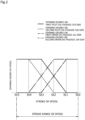
- the control valve 130 is configured to increase or reduce the opening degree on drain oil passages 131 and 134 sides and the opening degree on pilot oil passages 133 and 136 sides according to the stroke of the piston 120. In addition, the control valve 130 is always opened at a substantially constant opening degree with respect to the pilot oil passages 132 and 135. A detailed operation of the control valve 130 will be described later.
- a first variable throttle 90 and the first adjustable slow return valve 9 including a first check valve 92 connected in parallel to the first variable throttle 90 are disposed.
- a second variable throttle 90A and the second adjustable slow return valve 9A including a second check valve 92A connected in parallel to the second variable throttle 90A are disposed.
- first variable throttle 90 is narrower in opening degree than the second variable throttle 90A.
- the second pressure-increasing device 10A mainly includes a casing 110A, a piston 120A, a spring 140A, and a rod 150A, and has the same configuration as that of the first pressure-increasing device 10 except that the control valve 130 is not provided.
- the piston 120A partitions a space inside the large-diameter cylindrical portion 111 of the casing 110A into the back pressure chamber 10A-1 and the pressure-increasing chamber 10A-2.
- the oil passage 82 is connected to the back pressure chamber 10A-1.
- the oil passage 101 is connected to the pressure-increasing chamber 10A-2.
- a drain oil passage 113A is connected to a drain chamber 10A-3.
- a state where the rod 150A penetrating through a bottom of a small-diameter cylindrical portion 112 of the casing 110A is in contact with the piston 120A is held by a force from pressure acting on the back pressure surface 121a of the piston 120A and by a biasing force of the spring 140A.
- FIGS. 1 to 11 a pressure-increasing cycle performed by the pressure-increasing devices 10 and 10A will be described with reference to FIGS. 1 to 11 .
- the pressure-increasing devices 10 and 10A since the pressure-increasing devices 10 and 10A have substantially the same configuration, and the operations thereof are the same, duplicate descriptions will be omitted or simplified.
- the pressure-increasing devices 10 and 10A and each oil passage of FIGS 3 to 10 are schematically illustrated.
- the pressure-increasing devices 10 and 10A are so-called single-acting type pressure-increasing devices.
- the piston 120 is disposed at the start position inside the casing 110.
- the oil is stored in the back pressure chamber 10-1, the pressure-increasing chamber 10-2, and the drain chamber 10-3, and the pressure of the oil is substantially the same as that of the oil stored in the tank T that is open to the outside.
- the control valve 130 in a state where the piston 120 has reached the start position, the control valve 130 is at a maximum opening degree on the drain oil passages 131 and 134 sides, and is at a zero opening degree on the pilot oil passages 133 and 136 sides, namely, is fully closed.
- control valve 130 connects the oil passages 131 and 132. Substantially the same pressure as that of the oil in the tank T acts on the port 8-1 of the first switching valve 8.
- the first switching valve 8 connects the oil passages 70 and 80. This pressure is an initial value (refer to FIG. 11 ) in the present embodiment, and is smaller than a predetermined value at which the position of the switching valve 8 is switched.
- control valve 130 connects the oil passages 134 and 135. Substantially the same pressure as that of the oil in the tank T acts on the port 8A-1 of the second switching valve 8A.
- the second switching valve 8A connects the oil passages 73 and 82.
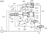
- the switch 15 When the increase of the pressure by the pressure-increasing devices 10 and 10A is started, the switch 15 is set to an ON state. Accordingly, the electromagnetic switching valve 7 connects the oil passages 61 and 70, and as illustrated in FIG. 3 , some of the hydraulic oil delivered from the pilot pump 6 passes through the oil passage 70, the first switching valve 8, and the oil passage 80, and is delivered to the back pressure chamber 10-1 of the first pressure-increasing device 10.
- the back pressure surface 121a of the piston 120 as an effective pressure-receiving area of the back pressure chamber 10-1 is wider in area than the pressure-increasing surface 121b of the piston 120 as an effective pressure-receiving area of the pressure-increasing chamber 10-2.
- a pressing force obtained by multiplying the fluid pressure of the hydraulic oil delivered from the pilot pump 6 by the area of the back pressure surface 121a is generated to press the piston 120 to the end position side.
- the hydraulic oil in the pressure-increasing chamber 10-2 is increased in pressure to a pressure calculated by dividing the pressing force by the area of the pressure-increasing surface 121b, and is sequentially delivered toward the oil passage 100 along with the movement of the piston 120.
- the working fluid passes through the branch oil passage 73, the second switching valve 8A, and the oil passage 82, and is also delivered to the back pressure chamber 10A-1 of the second pressure-increasing device 10A. Accordingly, in the second pressure-increasing device 10A as well, the hydraulic oil in the pressure-increasing chamber 10A-2 is sequentially delivered toward the oil passage 100A along with the movement of the piston 120A.
- the pistons 120 and 120A of the pressure-increasing devices 10 and 10A move at substantially the same speed.
- the control valve 130 starts to be displaced from a minimum stroke st0 toward a maximum stroke st5. After a stroke st1, the control valve 130 narrows the opening degree on the first drain oil passage 131 side, and widens the opening degree on the first pilot oil passage 133 side according to the stroke of the piston 120.
- the opening degree of the control valve 130 on the first pilot oil passage 133 side becomes wider than the opening degree on the first drain oil passage 131 side. For this reason, the pilot fluid is loaded on the port 8-1 of the first switching valve 8 through the first variable throttle 90 (refer to FIG. 11 ).
- the control valve 130 narrows the opening degree on the second drain oil passage 134 side, and widens the opening degree on the second pilot oil passage 136 side.
- the control valve 130 sets the opening degree on the first drain oil passage 131 side to zero, namely, fully closed, and sets the opening degree on the first pilot oil passage 133 side to its maximum, namely, fully opened.
- the control valve 130 sets the opening degree on the second drain oil passage 134 side to fully closed, and sets the opening degree on the second pilot oil passage 136 side to fully opened.
- the first variable throttle 90 is sufficiently narrower in opening degree than the second variable throttle 90A (refer to FIG. 3 ). Accordingly, the pilot fluid pressure acting on the port 8A-1 of the second switching valve 8A reaches the predetermined value or more at an earlier timing than the pilot fluid pressure acting on the port 8-1 of the first switching valve 8 (refer to FIG. 11 ).
- the pilot fluid pressure acting on the port 8A-1 of the second switching valve 8A reaches the predetermined value or more (refer to FIG. 11 ). Accordingly, as illustrated in FIG. 4 , the second switching valve 8A switches to an actuation position, and connects the oil passages 82 and 83.
- the hydraulic oil in the back pressure chamber 10A-1 of the second pressure-increasing device 10A is discharged to the tank T through the oil passage 82, the second switching valve 8A, and the tank-side oil passage 83.
- the pilot fluid pressure acting on the port 8A-1 becomes substantially the same pressure as that of the hydraulic oil delivered from the pilot pump 6 (refer to FIG. 11 ) .
- the small-diameter portion 122 of the piston 120 comes into contact with the bottom of the small-diameter cylindrical portion 112 of the casing 110. Accordingly, the piston 120 reaches the end position, and the movement of the piston 120 is restricted. At this time, a slight volume is ensured in the pressure-increasing chamber 10-2. Namely, the small-diameter portion 122 of the piston 120 and the small-diameter cylindrical portion 112 of the casing 110 function as spacers.
- the pressure-increasing devices 10 and 10A are connected in parallel with respect to the oil passage 70. Accordingly, for example, compared to a configuration in which the compression efficiency per unit time by cooperation between the pressure-increasing devices 10 and 10A is achieved by one pressure-increasing device, the hydraulic oil amount per unit time flowing into each of the pressure-increasing devices 10 and 10A is reduced. For this reason, the peak pressure generated when one of the pistons 120 and 120A of the pressure-increasing devices 10 and 10A reaches or stops at the end position is relatively reduced.
- the pressure-increasing chamber 10-2 of the first pressure-increasing device 10 and the pressure-increasing chamber 10A-2 of the second pressure-increasing device 10A are connected in parallel so as to be able to communicate with each other through the oil passages 100 and 100A. Accordingly, when the piston 120 of the first pressure-increasing device 10 stops, the pressure-increasing chamber 10A-2 of the second pressure-increasing device 10A functions as a buffer. Similarly, when the piston 120A of the second pressure-increasing device 10A stops, the pressure-increasing chamber 10-2 of the first pressure-increasing device 10 functions as a buffer. In such a manner, the fluid circuit can reduce vibration or noise generated when the pressure of the hydraulic oil is increased.
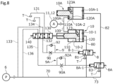
- the first switching valve 8 switches to an actuation position, and connects the oil passages 80 and 81. Accordingly, the hydraulic oil in the back pressure chamber 10-1 of the first pressure-increasing device 10 is discharged to the tank T through the oil passage 80, the first switching valve 8, and the tank-side oil passage 81.
- the piston 120A of the second pressure-increasing device 10A reaches the start position before the piston 120 of the first pressure-increasing device 10 reaches the start position.
- the piston 120 of the first pressure-increasing device 10 is in the middle of movement toward the start position.
- control valve 130 widens the opening degree on the second drain oil passage 134 side, and narrows the opening degree on the second pilot oil passage 136 side according to the stroke of the piston 120.
- the opening degree of the control valve 130 on the second pilot oil passage 136 side becomes wider than the opening degree on the second drain oil passage 134 side. For this reason, the pilot fluid is discharged to the tank T through the second variable throttle 90A and the second check valve 92A.
- the control valve 130 widens the opening degree on the first drain oil passage 131 side, and narrows the opening degree on the first pilot oil passage 133 side.
- the control valve 130 sets the opening degree on the second drain oil passage 134 side to fully opened, and sets the opening degree on the first pilot oil passage 133 side to fully closed.
- the control valve 130 sets the opening degree on the first drain oil passage 131 side to fully opened, and sets the opening degree on the first pilot oil passage 133 side to fully closed.
- the pilot fluid pressure acting on the port 8A-1 of the second switching valve 8A becomes less than the predetermined value (refer to FIG. 11 ). Accordingly, the second switching valve 8A switches to an initial position, and connects the oil passages 73 and 82 (refer to FIG. 11 ). Namely, the piston 120A of the second pressure-increasing device 10A starts to move toward the end position earlier than when the piston 120 of the first pressure-increasing device 10 reaches the start position.
- the second switching valve 8A switches from the actuation position to the initial position in a shorter time than the time it takes for the second switching valve 8A to switch from the initial position to the actuation position.
- the adjustable slow return valves 9 and 9A can increase the number of strokes per unit time.
- the speed at which the pistons 120 and 120A move from the end positions toward the start positions is described as being higher than the speed at which the pistons 120 and 120A move from the start positions toward the end positions; however, the movement speeds of the pistons 120 and 120A may be the same.
- the piston 120 of the first pressure-increasing device 10 reaches the start position.
- the pilot fluid pressure acting on the port 8-1 of the first switching valve 8 becomes less than the predetermined value (refer to FIG. 11 ). Accordingly, the first switching valve 8 switches to an initial position, and connects the oil passages 70 and 80.
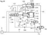
- the piston 120A of the second pressure-increasing device 10A reaches the end position before the piston 120 of the first pressure-increasing device 10 reaches the end position.
- the piston 120A of the second pressure-increasing device 10A stands by at the start position until the valve position of the control valve 130 is switched and the valve position of the second switching valve 8A is switched from the initial position to the actuation position (refer to FIG. 11 ).
- the piston 120A of the second pressure-increasing device 10A starts to move toward the start position when the valve position of the control valve 130 is switched and the valve position of the second switching valve 8A is switched to the actuation position (refer to FIG. 11 ).
- the piston 120 of the first pressure-increasing device 10 starts to move toward the start position when the control valve 130 is switched and the valve position of the first switching valve 8 is switched to the actuation position (refer to FIG. 11 ).
- the electromagnetic switching valve 7 connects the oil passages 61 and 70. Accordingly, the back pressure chambers 10-1 and 10A-1 are connected to the tank T. For this reason, both the pistons 120 and 120A move toward the start positions, and stop at the start positions.
- the fluid circuit of the present embodiment can repeatedly reciprocate two pistons 120 and 120A through cooperation between the switching valves 8 and 8A and the control valve 130 that are operated by the fluid pressure using the working fluid. Namely, a high fluid pressure can be continuously generated without performing electric control. Accordingly, electric control as in the related art is not required, so that the configuration of the fluid circuit can be simplified.
- two pressure-increasing devices 10 and 10A are such that the stroke timings of the pistons 120 and 120A are offset from each other. In other words, the pistons 120 and 120A are prevented from reaching the end positions at the same timing. Accordingly, the peak pressure of the hydraulic oil delivered from the two pressure-increasing devices 10 and 10A is decreased. For this reason, the fluid circuit can reduce vibration or noise generated when the pressure of the oil is increased.
- the fluid circuit can differentiate the phases of the two pistons 120 and 120A.
- the fluid circuit can offset the phases of the pistons 120 and 120A from each other.
- the pressure-increasing devices include the respective control valves of which the valve positions are switched according to the strokes of the individual pistons
- the timing that one control valve switches with respect to the other control valve changes relative thereto due to aging, external force, or the like.
- the control valve 130 is switched by the stroke of the piston 120 of the first pressure-increasing device 10.
- the influence of the change equally affects each of the pressure-increasing devices 10 and 10A. Accordingly, the phase of the piston 120A of the second pressure-increasing device 10A is accurately offset from that of the piston 120 of the first pressure-increasing device 10.
- the first adjustable slow return valve 9 includes a first check valve 92' that is opened in a state where the first pilot oil passages 132 and 133 are connected to each other.
- the second adjustable slow return valve 9A also includes a second check valve 92A' that is opened in a state where the second pilot oil passages 135 and 136 are connected to each other.
- control valve 130 first connects the second pilot oil passages 135 and 136, and then, connects the first pilot oil passages 132 and 133.
- the hydraulic oil delivered from the pilot pump 6 flows into the second pilot oil passage 135 before flowing into the first pilot oil passage 132.
- the second switching valve 8A switches to the actuation position earlier than the first switching valve 8.
- control valve 130 first connects the first drain oil passage 131 and the first pilot oil passage 132, and then, connects the second drain oil passage 134 and the second pilot oil passage 135.
- the configurations of the adjustable slow return valves 9 and 9A and the control valve 130 may be changed as appropriate.
- the working fluid is oil
- the present invention is not limited thereto, and the working fluid may be changed as appropriate as long as it is a fluid.
- each pressure-increasing device has been described as being of a single-acting type, but is not limited thereto, and may be of a double-acting type. With such a configuration, in a state where the piston is in stroke, since the working fluid delivered from the fluid supply device inevitably flows into one of the pressure-increasing devices, the generation of a peak pressure can be prevented. In addition, since only two pressure-increasing devices may be provided, the fluid circuit can be compactly configured.
- two pressure-increasing devices are connected to the corresponding switching valves; however, the present invention is not limited thereto, and for example, in a configuration in which three or more pressure-increasing devices are provided, two pressure-increasing devices may be such that the stroke directions of the respective pistons are switched by a common switching valve.
- the present invention is not limited thereto, and the method for differentiating the phases of the strokes of the two pistons may be changed as appropriate, for example, by differentiating one of the opening degrees of the control valve, the maximum strokes of the switching valves, the volumes of the oil passages connected to each port of the switching valve, the volumes of the cylinders of the pressure-increasing devices, the maximum strokes of the pistons of the pressure-increasing devices, and the biasing forces of the biasing means that return the switching valves to the initial positions.
- the adjustable slow return valves include the throttles
- the throttles may be non-variable throttles, may be various valves that are adjustable in flow passage cross-sectional area, may be configured such that the flow passage cross-sectional areas of the flow passages are different from each other, or may be changed as appropriate.
- the fluid supply device has been described as being the pilot circuit hydraulic pump, but is not limited thereto, may be the main circuit hydraulic pump, the actuator, the accumulator, or the like, or may be changed as appropriate.
- the shapes of the casing and the piston are not limited to those described in the embodiments, and the shapes of the casing and the piston may be changed as appropriate as long as the configuration is such that a difference between the effective pressure-receiving areas is provided.
- the biasing means is a spring
- the present invention is not limited thereto, and the biasing means may be a magnet or the like or may be changed as appropriate.
Landscapes
- Engineering & Computer Science (AREA)
- Mechanical Engineering (AREA)
- General Engineering & Computer Science (AREA)
- Physics & Mathematics (AREA)
- Fluid Mechanics (AREA)
- Fluid-Pressure Circuits (AREA)
- Supply Devices, Intensifiers, Converters, And Telemotors (AREA)
Abstract
Description
- The present invention relates to a fluid circuit, for example, a fluid circuit including pressure-increasing devices that increase a pressure of a working fluid.
- In various fields, there is known a fluid circuit that drives an actuator using a working fluid such as working oil delivered from a fluid supply device such as a pump. In such a fluid circuit, the actuator is actuated or the working fluid can be accumulated in an accumulator by a pressure-increasingz device capable of delivering the working fluid that is increased in pressure.
- For example, a fluid circuit illustrated in Patent Citation 1 includes a pump that delivers a working fluid; a tank that stores the working fluid; a pressure-increasing device capable of increasing the pressure of the working fluid; and an accumulator capable of accumulating the working fluid that is increased in pressure. The pressure-increasing device includes a cylinder having a T shape and a hollow structure when viewed from the front; a piston having a T shape when viewed from the front; and biasing means for biasing the piston to one side in an axial direction, and the piston is provided inside the cylinder so as to be reciprocatable in the axial direction.
- A space inside the cylinder is partitioned into a back pressure chamber and a pressure-increasing chamber by the piston. A flow passage communicating with the pump and a flow passage communicating with the tank are connected to the back pressure chamber, and the back pressure chamber is switched between communicating with the pump and communicating with the tank by a switching valve. A flow passage communicating with a tank side and a flow passage communicating with an accumulator side are connected to the pressure-increasing chamber. The piston is configured such that an area of an end surface facing the back pressure chamber is larger than an area of an end surface facing the pressure-increasing chamber.
- In the fluid circuit configured in such a manner, when the working fluid is delivered from the pump to the back pressure chamber in a state where the working fluid is stored in the pressure-increasing chamber, the piston moves to the other side in the axial direction. Accordingly, the piston pressurizes the working fluid in the pressure-increasing chamber. Then, the working fluid that is increased in pressure to a predetermined pressure or more is accumulated in the accumulator. In addition, when the valve position of the switching valve is switched so that the back pressure chamber and the tank communicate with each other and the hydraulic oil in the back pressure chamber starts to be discharged to the tank, the pressure in the back pressure chamber gradually decreases. Then, when a biasing force of the biasing means becomes larger than a force that moves the piston to the other side in the axial direction, the piston is moved to the one side in the axial direction.
- The pressure-increasing device described above is referred to as a so-called single-acting type. In contrast, there is also known a so-called double-acting type pressure-increasing device that reciprocates a piston by switching between chambers inside a cylinder into which a working fluid flows, according to the valve position of a switching valve.
- Patent Citation 1:
JP 2011-185417 A FIG. 1 ) - In the pressure-increasing device as disclosed in
Patent Citation 1, by switching the valve position of the switching valve according to the reciprocation of the piston, the working fluid that is increased in pressure can be continuously delivered to the accumulator. However, since an electromagnetic switching valve that can be switched by an electric signal is typically used as such a switching valve, a device for outputting an electric signal, a device for sensing a valve position, and the like are required, so that the entirety of the device is increased in size, which is a problem. In addition, a control program is also complicated, and there is also a program in terms of cost. - The present invention is conceived in view of such problems, and an object of the present invention is to provide a fluid circuit capable of continuously driving pressure-increasing devices with a simple configuration.
- In order to solve the foregoing problems, according to the present invention, there is provided a fluid circuit including: a fluid supply device that delivers a working fluid; and pressure-increasing devices that increase a pressure of the working fluid, wherein each of the pressure-increasing devices includes a cylinder connected to the fluid supply device, and a piston provided inside the cylinder so as to be reciprocatable in an axial direction, and delivers, from the cylinder, the working fluid having the pressure which is increased due to a movement of the piston toward a pressure-increasing chamber inside the cylinder by the working fluid delivered from the fluid supply device, the pressure-increasing devices are connected in parallel to the fluid supply device, a stroke direction of the piston of each of the pressure-increasing device is switched by the working fluid, and a phase of the piston of at least one of the pressure-increasing devices is different from a phase of the piston of remaining at least one of the pressure-increasing devices. According to the aforesaid feature of the present invention, the fluid circuit can repeatedly reciprocate the piston in each of the pressure-increasing devices using the working fluid. In addition, since the pressure-increasing devices are such that the stroke timings of the pistons are offset from each other, the peak pressure of the working fluid delivered from the pressure-increasing devices is small. For this reason, the fluid circuit can reduce vibration or noise generated when the pressure of the working fluid is increased.
- It may be preferable that each of pilot switching valves using the working fluid delivered from the fluid supply device, as a pilot fluid, is provided for each of the pressure-increasing devices, and each of the pressure-increasing devices switches the stroke directions of the pistons according to a valve position of each of the pilot switching valves. According to this preferable configuration, the phases of the pistons of the pressure-increasing devices can be differentiated with a simple configuration.
- It may be preferable that throttles are disposed between the fluid supply device and the respective pilot switching valves, and opening degrees of at least one of the throttles and remaining at least one of the throttles are different from each other. According to this preferable configuration, with a simple configuration, the phase of the piston of the at least one pressure-increasing device can be offset from that of the piston of the other pressure-increasing device.
- It may be preferable that the throttles are variable throttles. According to this preferable configuration, the timings of switching the valve positions of the switching valves are easily adjusted.
- It may be preferable that a pilot control valve that switches a flow of the pilot fluid of the pilot switching valves is provided, and the pilot control valve is switched by a movement of the piston of the one of the pressure-increasing devices. According to this preferable configuration, the phase of the piston of the other pressure-increasing device is accurately offset from that of the piston of the one pressure-increasing device.
- It may be preferable that the pressure-increasing chambers of the pressure-increasing devices are connected in parallel. According to this preferable configuration, when the piston of one of the pressure-increasing devices has moved and stopped at an end position, the peak pressure generated in the pressure-increasing chamber of the pressure-increasing device can flow into the pressure-increasing chamber of the other pressure-increasing device. Since the other pressure-increasing chamber functions as a so-called buffer to buffer the pressure, the fluid circuit can reduce vibration or noise generated when the pressure of the working fluid is increased.
-
-
FIG. 1 is a schematic diagram illustrating a fluid circuit including pressure-increasing devices, according to a first embodiment of the present invention. -
FIG. 2 is a graph for describing a characteristic of a spool valve in the first embodiment. -
FIG. 3 is a schematic diagram for describing a pressure-increasing cycle of a working fluid performed by the pressure-increasing device in the first embodiment. -
FIG. 4 is a schematic diagram for describing the pressure-increasing cycle of the working fluid performed by the pressure-increasing device in the first embodiment. -
FIG. 5 is a schematic diagram for describing the pressure-increasing cycle of the working fluid performed by the pressure-increasing device in the first embodiment. -
FIG. 6 is a schematic diagram for describing the pressure-increasing cycle of the working fluid performed by the pressure-increasing device in the first embodiment. -
FIG. 7 is a schematic diagram for describing the pressure-increasing cycle of the working fluid performed by the pressure-increasing device in the first embodiment. -
FIG. 8 is a schematic diagram for describing the pressure-increasing cycle of the working fluid performed by the pressure-increasing device in the first embodiment. -
FIG. 9 is a schematic diagram for describing the pressure-increasing cycle of the working fluid performed by the pressure-increasing device in the first embodiment. -
FIG. 10 is a schematic diagram for describing the pressure-increasing cycle of the working fluid performed by the pressure-increasing device in the first embodiment. -
FIG. 11 is a graph for describing changes of main parts of the fluid circuit during the pressure-increasing cycle in the first embodiment. -
FIG. 12 is a schematic diagram illustrating a fluid circuit including pressure-increasing devices, according to a second embodiment of the present invention. - Modes for implementing a fluid circuit according to the present invention will be described below based on embodiments.
- A fluid circuit according to a first embodiment of the present invention will be described with reference to
FIGS. 1 to 11 . - As illustrated in
FIG. 1 , the fluid circuit can be applied to, for example, hydraulic devices such as an actuator, a brake, a steering wheel, and a transmission in automobiles such as a normal passenger car and a truck or in work vehicles such as a hydraulic excavator, a forklift, a crane, and a garbage truck. Incidentally, the hydraulic circuit illustrated inFIG. 1 is one example of the fluid circuit of the present invention, and is not limited to a configuration ofFIG. 1 . - The fluid circuit according to the present embodiment is generally configured to move a workpiece W by actuating a
cylinder 5 as an actuator using hydraulic pressure. - The fluid circuit mainly includes a main circuit
hydraulic pump 2, aswitching valve 3, a hydraulicremote control valve 4, thecylinder 5, a pilot circuithydraulic pump 6 as a fluid supply device, an electromagnetic switching valve 7,switching valves slow return valves devices accumulators proportional switching valves - First, a configuration of a main circuit side on which the
cylinder 5 is actuated by the main circuit hydraulic pump 2 (hereinafter, simply referred to as the main pump 2) will be described. Themain pump 2 and the pilot circuithydraulic pump 6 driven by power from adrive mechanism 1 such as an engine of a vehicle deliver hydraulic oil tooil passages - The hydraulic oil delivered from the
main pump 2 flows into theswitching valve 3 throughoil passages - The switching
valve 3 is a six-port and three-position type open center switching valve. The switchingvalve 3 at a neutral position connects theoil passage 21 to a tank-side oil passage 30. The tank-side oil passage 30 is connected to a tank T. For this reason, the entire amount of the hydraulic oil delivered from themain pump 2 is discharged to the tank T. - In addition, the switching
valve 3 at anextension position 3E connects theoil passage 20 and anoil passage 22 including a check valve to a head-side oil passage 50, and connects a rod-side oil passage 51 to a tank-side oil passage 31. The head-side oil passage 50 is connected to a head chamber 5-1 of thecylinder 5. The rod-side oil passage 51 is connected to a rod chamber 5-2 of thecylinder 5. The tank-side oil passage 31 is connected to the tank T. - In addition, the switching
valve 3 at acontraction position 3S connects theoil passages side oil passage 51, and connects the head-side oil passage 50 to the tank-side oil passage 31. - On the other hand, the hydraulic oil delivered from the pilot circuit hydraulic pump 6 (hereinafter, simply referred to as the pilot pump 6) is delivered to the hydraulic
remote control valve 4 through theoil passage 60. Incidentally, the hydraulic oil delivered to the hydraulicremote control valve 4 is not limited to the hydraulic oil delivered from the pilot pump, and may be a working fluid delivered from themain pump 2 and thecylinder 5, or may be changed as appropriate. - The hydraulic
remote control valve 4 that is a variable pressure reduction valve reduces the hydraulic oil of a pilot primary pressure delivered from thepilot pump 6, to a pilot secondary pressure corresponding to an operation amount of an operation lever 4-1. The hydraulic oil of the pilot secondary pressure is delivered to signal ports 3-1 and 3-2 of the switchingvalve 3 through pilotsignal oil passages 40 and 41. - Incidentally, of the hydraulic oil discharged from the
pilot pump 6, extra oil other than the working oil delivered to a first pressure-increasingdevice 10 side to be described later through anoil passage 61 instead of being delivered from the hydraulicremote control valve 4 to the signal ports 3-1 and 3-2 is discharged to the tank T through arelief oil passage 62 including a relief valve. - Operation of the
cylinder 5 according to operation of the hydraulicremote control valve 4 will be described. - The switching
valve 3 is switched to theextension position 3E by operating the operation lever 4-1 in an extension direction E. The hydraulic oil delivered from themain pump 2 flows into the head chamber 5-1 of thecylinder 5 through theoil passages oil passages pressure sensor 42 installed on the pilot signal oil passage 40 is input to the controller C. - The switching
valve 3 is switched to thecontraction position 3S by operating the operation lever 4-1 in a contraction direction S. The hydraulic oil delivered from themain pump 2 flows into the rod chamber 5-2 of thecylinder 5 through theoil passages oil passages pressure sensor 43 installed on the pilotsignal oil passage 41 is input to the controller C. - In addition, a
relief oil passage 23 including a relief valve is branched and connected to theoil passage 20. When the pressure in theoil passage 20 becomes abnormally high, the relief valve is opened, and the hydraulic oil is discharged from therelief oil passage 23 to the tank T. - Next, a configuration of a pilot circuit side that includes the first pressure-increasing
device 10 and that is connected to thepilot pump 6 will be described. Incidentally, theoil passage 60, the hydraulicremote control valve 4, the pilotsignal oil passages 40 and 41, and therelief oil passage 62 described above are included in the configuration of the pilot circuit side. - The electromagnetic switching valve 7 is provided in the
oil passage 61 that is branched and connected to theoil passage 60. When aswitch 15 is in an OFF state, the electromagnetic switching valve 7 disconnects theoil passage 61 and anoil passage 70. - In addition, the electromagnetic switching valve 7 to which an electric signal is input from the controller C through an
electric signal line 72 by setting theswitch 15 to an ON state connects theoil passage 61 and theoil passage 70. - The
first switching valve 8 as one switching valve is provided in theoil passage 70. Thefirst switching valve 8 is a pilot switching valve that switches between oil passages to be connected, according to pressure acting on a port 8-1. When the pressure acting on the port 8-1 is less than a predetermined value, thefirst switching valve 8 connectsoil passages first switching valve 8 connectsoil passages oil passage 80 is connected to a back pressure chamber 10-1 of the first pressure-increasingdevice 10 to be described later. The tank-side oil passage 81 is connected to the tank T. - In addition, a
branch oil passage 73 is branched and connected to theoil passage 70. Thesecond switching valve 8A as the other switching valve is provided in thebranch oil passage 73. Thesecond switching valve 8A has substantially the same configuration as that of thefirst switching valve 8. When the pressure acting on aport 8A-1 is less than a predetermined value, thesecond switching valve 8A connectsoil passages port 8A-1 is the predetermined value or more, thesecond switching valve 8A connectsoil passages oil passage 82 is connected to aback pressure chamber 10A-1 of the second pressure-increasingdevice 10A to be described later. The tank-side oil passage 83 is connected to the tank T. - The first pressure-increasing
device 10 is provided in theoil passage 80. The first pressure-increasingdevice 10 further increases the pressure of the hydraulic oil delivered from thepilot pump 6, and delivers the hydraulic oil to anoil passage 100. Acheck valve 100R is provided in theoil passage 100. - The second pressure-increasing
device 10A is provided in theoil passage 82. The second pressure-increasingdevice 10A further increases the pressure of the hydraulic oil delivered from thepilot pump 6, and delivers the hydraulic oil to anoil passage 100A. Theoil passage 100A is branched and connected to theoil passage 100. Namely, a pressure-increasing chamber 10-2 of the first pressure-increasingdevice 10 and a pressure-increasingchamber 10A-2 of the second pressure-increasingdevice 10A are connected in parallel by theoil passages devices - An
oil passage 101 including two check valves and anoil passage 102 including two other check valves are branched and connected to theoil passage 100. - In the
oil passage 101, theaccumulator 11 and apressure sensor 103 that detects a pressure of theaccumulator 11 are connected to each other between the two check valves. In addition, the electromagneticproportional switching valve 13 is connected to a downstream side of the two check valves in theoil passage 101. - In the
oil passage 102, theaccumulator 12 and apressure sensor 104 that detects a pressure of theaccumulator 12 are connected to each other between the two check valves. In addition, the electromagneticproportional switching valve 14 is connected to a downstream side of the two check valves in theoil passage 102. - The electromagnetic
proportional switching valves - The controller C controls the electromagnetic
proportional switching valves pressure sensors proportional switching valve 13 will be described as an example. - When the pressure in the
accumulator 11 decreases, an electric signal is input from the controller C, and the electromagneticproportional switching valve 13 is closed. Accordingly, theaccumulator 11 can accumulate the hydraulic oil that is increased in pressured and delivered from the first pressure-increasingdevice 10. - In addition, when the pressure in the
accumulator 11 increases, the controller C inputs an electric signal to the electromagneticproportional switching valve 13. The electromagneticproportional switching valve 13 connectsoil passages accumulator 11 is recovered into the head chamber 5-1 of thecylinder 5 through theoil passages - In addition, by alternately switching the electromagnetic
proportional switching valves accumulators - In addition, a
relief oil passage 108 including a relief valve is branched and connected to theoil passage 100. When the accumulated hydraulic oil in theaccumulators relief oil passage 108. - Next, the pressure-increasing
devices device 10A has substantially the same configuration as that of the first pressure-increasingdevice 10, duplicate descriptions will be omitted or simplified. In addition, in the present embodiment, aspring 140 side of the first pressure-increasingdevice 10 and an opposite side will be described as an end position side (namely, a lower side in the drawings) and a start position side (namely, an upper side in the drawings), respectively. A start position and an end position are the positions of apiston 120 to be described later. - As illustrated in
FIG. 1 , the first pressure-increasingdevice 10 mainly includes acasing 110 as a cylinder, thepiston 120, acontrol valve 130, aspring 140 as biasing means, and arod 150. Thepiston 120 is provided to be movable inside thecasing 110 in an axial direction. Thespring 140 biases thepiston 120 toward the start position side. - The
casing 110 is formed in a substantially T-shaped stepped cylindrical shape when viewed from the front, and includes a large-diametercylindrical portion 111 and a small-diametercylindrical portion 112. - The
oil passage 80 is connected to the start position side of the large-diametercylindrical portion 111, and theoil passage 100 is connected to the end position side of the large-diametercylindrical portion 111 on a radially outer side of the small-diametercylindrical portion 112. - An
oil passage 113 connected to the tank T is connected to a peripheral wall of the small-diametercylindrical portion 112. - The
piston 120 is formed in a T-shaped stepped columnar shape when viewed from the front, and includes a large-diameter portion 121 and a small-diameter portion 122. - The large-
diameter portion 121 is formed such that an outer peripheral surface of the large-diameter portion 121 is slidable along an inner peripheral surface of the large-diametercylindrical portion 111 of thecasing 110. The small-diameter portion 122 is formed such that an outer peripheral surface of the small-diameter portion 122 is slidable along an inner peripheral surface of the small-diametercylindrical portion 112 of thecasing 110. - In the
casing 110 in which thepiston 120 is accommodated, a space inside the large-diametercylindrical portion 111 is partitioned into the back pressure chamber 10-1 and the pressure-increasing chamber 10-2 by the large-diameter portion 121 of thepiston 120. - A
back pressure surface 121a of the large-diameter portion 121 of thepiston 120 faces the back pressure chamber 10-1. An annular pressure-increasingsurface 121b of the large-diameter portion 121 of thepiston 120 faces the pressure-increasing chamber 10-2. - The
oil passage 80 is connected to the back pressure chamber 10-1, and theoil passage 100 is connected to the pressure-increasing chamber 10-2. In addition, a spacer that restricts movement of thepiston 120 is disposed and fixed on the start position side in the back pressure chamber 10-1. - In addition, the back pressure chamber 10-1 and the pressure-increasing chamber 10-2 can communicate with each other through an
oil passage 123 provided to penetrate through the large-diameter portion 121 of thepiston 120. Theoil passage 123 includes a check valve. - In addition, a drain chamber 10-3 is partitioned off by the small-diameter
cylindrical portion 112 of thecasing 110 and the small-diameter portion 122 of thepiston 120. Theoil passage 113 communicates with the drain chamber 10-3. - The
piston 120 is configured to be reciprocatable between the start position and the end position. The start position is a position where theback pressure surface 121a of the large-diameter portion 121 comes into contact with the spacer in the back pressure chamber 10-1 so that movement of the large-diameter portion 121 in the same direction is restricted. The end position is a position where an end surface on the end position side of the small-diameter portion 122 comes into contact with an inner surface on the end position side of the drain chamber 10-3 so that movement of the small-diameter portion 122 in the same direction is restricted. - The
control valve 130 is a pilot control valve in this specification that controls pilot pressure to the respective ports 8-1 and 8A-1 of the switchingvalves - The
rod 150 is disposed between thepiston 120 and thecontrol valve 130. Therod 150 penetrates through a bottom of the small-diametercylindrical portion 112 of thecasing 110. A state where each of thepiston 120 and thecontrol valve 130 is in contact with therod 150 is held by a force from pressure acting on theback pressure surface 121a of the large-diameter portion 121 of thepiston 120 and by a biasing force of thespring 140. - Incidentally, the
piston 120 and thecontrol valve 130 may be integrated, for example, by welding therod 150 to one or both of thepiston 120 and thecontrol valve 130. - As illustrated in
FIGS. 1 and2 , drainoil passages pilot oil passages pilot oil passages control valve 130. - The first
drain oil passage 131 and the seconddrain oil passage 134 are connected to the tank T. The firstpilot oil passage 132 is connected to the port 8-1 of thefirst switching valve 8. The secondpilot oil passage 135 is connected to theport 8A-1 of thesecond switching valve 8A. The firstpilot oil passage 133 and the secondpilot oil passage 136 are branched and connected to theoil passage 70. - The
control valve 130 is configured to increase or reduce the opening degree ondrain oil passages pilot oil passages piston 120. In addition, thecontrol valve 130 is always opened at a substantially constant opening degree with respect to thepilot oil passages control valve 130 will be described later. - As illustrated in
FIG. 1 , in the firstpilot oil passage 132, a firstvariable throttle 90 and the first adjustableslow return valve 9 including afirst check valve 92 connected in parallel to the firstvariable throttle 90 are disposed. - In addition, in the second
pilot oil passage 135, similarly, a secondvariable throttle 90A and the second adjustableslow return valve 9A including asecond check valve 92A connected in parallel to the secondvariable throttle 90A are disposed. - In addition, the first
variable throttle 90 is narrower in opening degree than the secondvariable throttle 90A. - The second pressure-increasing
device 10A mainly includes acasing 110A, apiston 120A, aspring 140A, and arod 150A, and has the same configuration as that of the first pressure-increasingdevice 10 except that thecontrol valve 130 is not provided. - In the second pressure-increasing
device 10A, thepiston 120A partitions a space inside the large-diametercylindrical portion 111 of thecasing 110A into theback pressure chamber 10A-1 and the pressure-increasingchamber 10A-2. - The
oil passage 82 is connected to theback pressure chamber 10A-1. Theoil passage 101 is connected to the pressure-increasingchamber 10A-2. Adrain oil passage 113A is connected to adrain chamber 10A-3. - A state where the
rod 150A penetrating through a bottom of a small-diametercylindrical portion 112 of thecasing 110A is in contact with thepiston 120A is held by a force from pressure acting on theback pressure surface 121a of thepiston 120A and by a biasing force of thespring 140A. - Next, a pressure-increasing cycle performed by the pressure-increasing
devices FIGS. 1 to 11 . Incidentally, as described above, since the pressure-increasingdevices devices FIGS 3 to 10 are schematically illustrated. In addition, the pressure-increasingdevices - First, a state before the pressure increase by the pressure-increasing
devices FIG. 1 , theswitch 15 is in an OFF state, and the electromagnetic switching valve 7 disconnects theoil passages - In the pressure-increasing
device 10 before the pressure increase is started, thepiston 120 is disposed at the start position inside thecasing 110. - In the pressure-increasing
device 10, the oil is stored in the back pressure chamber 10-1, the pressure-increasing chamber 10-2, and the drain chamber 10-3, and the pressure of the oil is substantially the same as that of the oil stored in the tank T that is open to the outside. - As illustrated in
FIG. 2 , in a state where thepiston 120 has reached the start position, thecontrol valve 130 is at a maximum opening degree on thedrain oil passages pilot oil passages - Accordingly, the
control valve 130 connects theoil passages first switching valve 8. Thefirst switching valve 8 connects theoil passages FIG. 11 ) in the present embodiment, and is smaller than a predetermined value at which the position of the switchingvalve 8 is switched. - Similarly, the
control valve 130 connects theoil passages port 8A-1 of thesecond switching valve 8A. Thesecond switching valve 8A connects theoil passages - When the increase of the pressure by the pressure-increasing
devices switch 15 is set to an ON state. Accordingly, the electromagnetic switching valve 7 connects theoil passages FIG. 3 , some of the hydraulic oil delivered from thepilot pump 6 passes through theoil passage 70, thefirst switching valve 8, and theoil passage 80, and is delivered to the back pressure chamber 10-1 of the first pressure-increasingdevice 10. - Here, the
back pressure surface 121a of thepiston 120 as an effective pressure-receiving area of the back pressure chamber 10-1 is wider in area than the pressure-increasingsurface 121b of thepiston 120 as an effective pressure-receiving area of the pressure-increasing chamber 10-2. - Accordingly, in the back pressure chamber 10-1, a pressing force obtained by multiplying the fluid pressure of the hydraulic oil delivered from the
pilot pump 6 by the area of theback pressure surface 121a is generated to press thepiston 120 to the end position side. - Accordingly, the hydraulic oil in the pressure-increasing chamber 10-2 is increased in pressure to a pressure calculated by dividing the pressing force by the area of the pressure-increasing
surface 121b, and is sequentially delivered toward theoil passage 100 along with the movement of thepiston 120. - Incidentally, in this description, since the pressure of the oil in the drain chamber 10-3 is substantially constant regardless of the movement of the
piston 120, and the oil repeatedly flows in and out as thepiston 120 moves, the description thereof will be omitted. - In addition, similarly to the first pressure-increasing
device 10, the working fluid passes through thebranch oil passage 73, thesecond switching valve 8A, and theoil passage 82, and is also delivered to theback pressure chamber 10A-1 of the second pressure-increasingdevice 10A. Accordingly, in the second pressure-increasingdevice 10A as well, the hydraulic oil in the pressure-increasingchamber 10A-2 is sequentially delivered toward theoil passage 100A along with the movement of thepiston 120A. - Incidentally, as illustrated in
FIG. 11 , thepistons devices - As illustrated in
FIG. 2 , when thepiston 120 of the first pressure-increasingdevice 10 starts to move from the start position toward the end position, thecontrol valve 130 starts to be displaced from a minimum stroke st0 toward a maximum stroke st5. After a stroke st1, thecontrol valve 130 narrows the opening degree on the firstdrain oil passage 131 side, and widens the opening degree on the firstpilot oil passage 133 side according to the stroke of thepiston 120. - Then, after a stroke st2, the opening degree of the
control valve 130 on the firstpilot oil passage 133 side becomes wider than the opening degree on the firstdrain oil passage 131 side. For this reason, the pilot fluid is loaded on the port 8-1 of thefirst switching valve 8 through the first variable throttle 90 (refer toFIG. 11 ). In addition, after the stroke st2, thecontrol valve 130 narrows the opening degree on the seconddrain oil passage 134 side, and widens the opening degree on the secondpilot oil passage 136 side. - Further, the movement of the
piston 120 progresses, and after a stroke st3, thecontrol valve 130 sets the opening degree on the firstdrain oil passage 131 side to zero, namely, fully closed, and sets the opening degree on the firstpilot oil passage 133 side to its maximum, namely, fully opened. In addition, after a stroke st4, thecontrol valve 130 sets the opening degree on the seconddrain oil passage 134 side to fully closed, and sets the opening degree on the secondpilot oil passage 136 side to fully opened. - By the way, the first
variable throttle 90 is sufficiently narrower in opening degree than the secondvariable throttle 90A (refer toFIG. 3 ). Accordingly, the pilot fluid pressure acting on theport 8A-1 of thesecond switching valve 8A reaches the predetermined value or more at an earlier timing than the pilot fluid pressure acting on the port 8-1 of the first switching valve 8 (refer toFIG. 11 ). - For this reason, before the
piston 120 reaches the end position, the pilot fluid pressure acting on theport 8A-1 of thesecond switching valve 8A reaches the predetermined value or more (refer toFIG. 11 ). Accordingly, as illustrated inFIG. 4 , thesecond switching valve 8A switches to an actuation position, and connects theoil passages - Accordingly, the hydraulic oil in the
back pressure chamber 10A-1 of the second pressure-increasingdevice 10A is discharged to the tank T through theoil passage 82, thesecond switching valve 8A, and the tank-side oil passage 83. - Thereafter, the pilot fluid pressure acting on the
port 8A-1 becomes substantially the same pressure as that of the hydraulic oil delivered from the pilot pump 6 (refer toFIG. 11 ) . - Then, when the pressure in the
back pressure chamber 10A-1 decreases, thepiston 120A starts to move toward a start position due to the biasing force of thespring 140A (refer toFIG. 1 ). As thepiston 120A moves, some of the oil in theback pressure chamber 10A-1 flows into the pressure-increasingchamber 10A-2 through anoil passage 123A. - As illustrated in
FIG. 5 , in the middle of the advancement of thepiston 120A of the second pressure-increasingdevice 10A toward the start position, in the first pressure-increasingdevice 10, the small-diameter portion 122 of thepiston 120 comes into contact with the bottom of the small-diametercylindrical portion 112 of thecasing 110. Accordingly, thepiston 120 reaches the end position, and the movement of thepiston 120 is restricted. At this time, a slight volume is ensured in the pressure-increasing chamber 10-2. Namely, the small-diameter portion 122 of thepiston 120 and the small-diametercylindrical portion 112 of thecasing 110 function as spacers. - As described above, the pressure-increasing
devices oil passage 70. Accordingly, for example, compared to a configuration in which the compression efficiency per unit time by cooperation between the pressure-increasingdevices devices pistons devices - In addition, the pressure-increasing chamber 10-2 of the first pressure-increasing
device 10 and the pressure-increasingchamber 10A-2 of the second pressure-increasingdevice 10A are connected in parallel so as to be able to communicate with each other through theoil passages piston 120 of the first pressure-increasingdevice 10 stops, the pressure-increasingchamber 10A-2 of the second pressure-increasingdevice 10A functions as a buffer. Similarly, when thepiston 120A of the second pressure-increasingdevice 10A stops, the pressure-increasing chamber 10-2 of the first pressure-increasingdevice 10 functions as a buffer. In such a manner, the fluid circuit can reduce vibration or noise generated when the pressure of the hydraulic oil is increased. - Thereafter, when the pilot fluid pressure acting on the port 8-1 of the
first switching valve 8 reaches the predetermined value or more, thefirst switching valve 8 switches to an actuation position, and connects theoil passages device 10 is discharged to the tank T through theoil passage 80, thefirst switching valve 8, and the tank-side oil passage 81. - Then, when the pressure in the back pressure chamber 10-1 decreases, the
piston 120 starts to move toward the start position due to the biasing force of thespring 140. Accordingly, thecontrol valve 130 starts to be displaced from the maximum stroke st5 toward the minimum stroke st0. - As the
piston 120 moves toward the start position, some of the oil in the back pressure chamber 10-1 flows into the pressure-increasing chamber 10-2 through theoil passage 123. - Referring to
FIG. 6 , thepiston 120A of the second pressure-increasingdevice 10A reaches the start position before thepiston 120 of the first pressure-increasingdevice 10 reaches the start position. On the other hand, thepiston 120 of the first pressure-increasingdevice 10 is in the middle of movement toward the start position. - By the way, after the stroke st4, the
control valve 130 widens the opening degree on the seconddrain oil passage 134 side, and narrows the opening degree on the secondpilot oil passage 136 side according to the stroke of thepiston 120. - Then, after the stroke st3, the opening degree of the
control valve 130 on the secondpilot oil passage 136 side becomes wider than the opening degree on the seconddrain oil passage 134 side. For this reason, the pilot fluid is discharged to the tank T through the secondvariable throttle 90A and thesecond check valve 92A. In addition, after the stroke st3, thecontrol valve 130 widens the opening degree on the firstdrain oil passage 131 side, and narrows the opening degree on the firstpilot oil passage 133 side. - Further, the movement of the
piston 120 progresses, and after the stroke st2, thecontrol valve 130 sets the opening degree on the seconddrain oil passage 134 side to fully opened, and sets the opening degree on the firstpilot oil passage 133 side to fully closed. In addition, after the stroke st1, thecontrol valve 130 sets the opening degree on the firstdrain oil passage 131 side to fully opened, and sets the opening degree on the firstpilot oil passage 133 side to fully closed. - For this reason, as illustrated in
FIG. 6 , after thepiston 120A of the second pressure-increasingdevice 10A has reached the start position, the pilot fluid pressure acting on theport 8A-1 of thesecond switching valve 8A becomes less than the predetermined value (refer toFIG. 11 ). Accordingly, thesecond switching valve 8A switches to an initial position, and connects theoil passages 73 and 82 (refer toFIG. 11 ). Namely, thepiston 120A of the second pressure-increasingdevice 10A starts to move toward the end position earlier than when thepiston 120 of the first pressure-increasingdevice 10 reaches the start position. - In such a manner, after the
piston 120A of the second pressure-increasingdevice 10A has reached the start position, the timing that the valve position of thecontrol valve 130 is switched, the flow passage cross-sectional areas of theoil passages second check valve 92A are adjusted such that the pilot fluid pressure acting on theport 8A-1 of thesecond switching valve 8A becomes less than the predetermined value. - In addition, in a state where the second
drain oil passage 134 and thepilot oil passage 135 are connected to each other, thesecond check valve 92A that is wider in opening degree than the secondvariable throttle 90A is opened. For this reason, thesecond switching valve 8A switches from the actuation position to the initial position in a shorter time than the time it takes for thesecond switching valve 8A to switch from the initial position to the actuation position. In other words, compared to a configuration in which the opening degrees of the throttles or the flow passage cross-sectional areas of the flow passages are simply different between the pilot flow passages on afirst switching valve 8 side and asecond switching valve 8A side, the adjustableslow return valves - Incidentally, in the present embodiment, as illustrated in
FIG. 11 , the speed at which thepistons pistons pistons - Thereafter, as illustrated in
FIG. 7 , thepiston 120 of the first pressure-increasingdevice 10 reaches the start position. In addition, the pilot fluid pressure acting on the port 8-1 of thefirst switching valve 8 becomes less than the predetermined value (refer toFIG. 11 ). Accordingly, thefirst switching valve 8 switches to an initial position, and connects theoil passages - As illustrated in
FIG. 8 , thepiston 120A of the second pressure-increasingdevice 10A reaches the end position before thepiston 120 of the first pressure-increasingdevice 10 reaches the end position. Thepiston 120A of the second pressure-increasingdevice 10A stands by at the start position until the valve position of thecontrol valve 130 is switched and the valve position of thesecond switching valve 8A is switched from the initial position to the actuation position (refer toFIG. 11 ). - As illustrated in
FIG. 9 , thepiston 120A of the second pressure-increasingdevice 10A starts to move toward the start position when the valve position of thecontrol valve 130 is switched and the valve position of thesecond switching valve 8A is switched to the actuation position (refer toFIG. 11 ). - As illustrated in
FIG. 10 , thepiston 120 of the first pressure-increasingdevice 10 starts to move toward the start position when thecontrol valve 130 is switched and the valve position of thefirst switching valve 8 is switched to the actuation position (refer toFIG. 11 ). - Thereafter, when the
switch 15 is in an ON state, the cycles illustrated inFIGS. 6 to 10 can be repeatedly performed. Namely, the first pressure-increasingdevice 10 and the second pressure-increasingdevice 10A can be continuously driven using the fluid pressure. - In addition, when the
switch 15 is set to an OFF state, as illustrated inFIG. 1 , the electromagnetic switching valve 7 connects theoil passages pistons - As described above, the fluid circuit of the present embodiment can repeatedly reciprocate two
pistons valves control valve 130 that are operated by the fluid pressure using the working fluid. Namely, a high fluid pressure can be continuously generated without performing electric control. Accordingly, electric control as in the related art is not required, so that the configuration of the fluid circuit can be simplified. - In addition, two pressure-increasing
devices pistons pistons devices - In addition, with a simple configuration in which the stroke directions of the corresponding
pistons switching valves pistons - In addition, with a simple configuration in which the opening degrees of the variable throttles 90 and 90A are different from each other, the fluid circuit can offset the phases of the
pistons - In addition, in differentiating the phases of the strokes of the two
pistons valves - In addition, for example, when the pressure-increasing devices include the respective control valves of which the valve positions are switched according to the strokes of the individual pistons, it is considered that the timing that one control valve switches with respect to the other control valve changes relative thereto due to aging, external force, or the like. In contrast, in the fluid circuit of this specification, the
control valve 130 is switched by the stroke of thepiston 120 of the first pressure-increasingdevice 10. For this reason, even when a change occurs in the timing that the valve position of thecontrol valve 130 is switched, the influence of the change equally affects each of the pressure-increasingdevices piston 120A of the second pressure-increasingdevice 10A is accurately offset from that of thepiston 120 of the first pressure-increasingdevice 10. - Next, a fluid circuit according to a second embodiment of the present invention will be described with reference to
FIG. 12 . Incidentally, the same reference signs are assigned to the same components as the components illustrated in the first embodiment, and the duplicate descriptions will be omitted. - As illustrated in
FIG. 12 , the first adjustableslow return valve 9 includes a first check valve 92' that is opened in a state where the firstpilot oil passages slow return valve 9A also includes asecond check valve 92A' that is opened in a state where the secondpilot oil passages - In addition, when the
piston 120 moves from the start position toward the end position, thecontrol valve 130 first connects the secondpilot oil passages pilot oil passages - Accordingly, the hydraulic oil delivered from the
pilot pump 6 flows into the secondpilot oil passage 135 before flowing into the firstpilot oil passage 132. For this reason, thesecond switching valve 8A switches to the actuation position earlier than thefirst switching valve 8. - In addition, when the
piston 120 moves from the end position toward the start position, thecontrol valve 130 first connects the firstdrain oil passage 131 and the firstpilot oil passage 132, and then, connects the seconddrain oil passage 134 and the secondpilot oil passage 135. - Accordingly, it takes longer time for the pilot fluid pressure to become less than the predetermined value in the first
pilot oil passage 132 in which the firstvariable throttle 90 having a sufficiently narrower opening degree than the secondvariable throttle 90A is disposed than in the secondpilot oil passage 135 in which the secondvariable throttle 90A is disposed. For this reason, thesecond switching valve 8A switches to the initial position earlier than thefirst switching valve 8. - In such a manner, the configurations of the adjustable
slow return valves control valve 130 may be changed as appropriate. - The embodiments of the present invention have been described above with reference to the drawings; however, the specific configurations are not limited to the embodiments, and modifications or additions that are made without departing from the scope of the present invention are included in the present invention.
- For example, in the embodiments, a configuration in which the working fluid is oil has been described; however, the present invention is not limited thereto, and the working fluid may be changed as appropriate as long as it is a fluid.
- In addition, in the embodiments, a configuration in which two pressure-increasing devices are provided has been described; however, the present invention is not limited thereto, and three or more pressure-increasing devices may be provided. With such a configuration, since the piston of at least one of a plurality of the pressure-increasing devices can be moved from the start position to the end position, the generation of a peak pressure can be prevented.
- In the embodiments, each pressure-increasing device has been described as being of a single-acting type, but is not limited thereto, and may be of a double-acting type. With such a configuration, in a state where the piston is in stroke, since the working fluid delivered from the fluid supply device inevitably flows into one of the pressure-increasing devices, the generation of a peak pressure can be prevented. In addition, since only two pressure-increasing devices may be provided, the fluid circuit can be compactly configured.
- In addition, a configuration in which two pressure-increasing devices are connected to the corresponding switching valves has been described; however, the present invention is not limited thereto, and for example, in a configuration in which three or more pressure-increasing devices are provided, two pressure-increasing devices may be such that the stroke directions of the respective pistons are switched by a common switching valve.
- In addition, in the embodiments, a configuration in which two accumulators are disposed on a downstream side of the pressure-increasing devices has been described; however, the present invention is not limited thereto, and the number of the accumulators may be one or may be three or more.
- In addition, in the embodiments, a configuration in which the control valve connects a pump-side flow passage and a drain-side flow passage to a switching valve-side flow passage at the same timing has been described; however, the present invention is not limited thereto, and a configuration in which only one of the pump-side flow passage and the drain-side flow passage is connected to the switching valve-side flow passage may be employed.
- In addition, in the embodiments, a configuration in which the timing that the opening degree on the first pressure-increasing device side becomes its maximum or zero and the timing that the opening degree on a second pressure-increasing device side becomes its maximum or zero are different from each other has been described; however, the present invention is not limited thereto, and the timings may be the same.
- In addition, in the embodiments, a configuration in which the phases of the strokes of two pistons are differentiated according to the opening degrees of the throttles has been described; however, the present invention is not limited thereto, and the method for differentiating the phases of the strokes of the two pistons may be changed as appropriate, for example, by differentiating one of the opening degrees of the control valve, the maximum strokes of the switching valves, the volumes of the oil passages connected to each port of the switching valve, the volumes of the cylinders of the pressure-increasing devices, the maximum strokes of the pistons of the pressure-increasing devices, and the biasing forces of the biasing means that return the switching valves to the initial positions.
- In addition, in the embodiments, a configuration in which the adjustable slow return valves include the throttles has been described; however, the present invention is not limited thereto, and the throttles may be non-variable throttles, may be various valves that are adjustable in flow passage cross-sectional area, may be configured such that the flow passage cross-sectional areas of the flow passages are different from each other, or may be changed as appropriate.
- In addition, in the embodiments, the fluid supply device has been described as being the pilot circuit hydraulic pump, but is not limited thereto, may be the main circuit hydraulic pump, the actuator, the accumulator, or the like, or may be changed as appropriate.
- In addition, in the embodiments, a configuration in which the hydraulic oil delivered from the pressure-increasing device is delivered to the accumulator has been described; however, the present invention is not limited thereto, and the hydraulic oil may be delivered to the actuator.
- In addition, the shapes of the casing and the piston are not limited to those described in the embodiments, and the shapes of the casing and the piston may be changed as appropriate as long as the configuration is such that a difference between the effective pressure-receiving areas is provided.
- In addition, in the first and second embodiments, a configuration in which the biasing means is a spring has been described; however, the present invention is not limited thereto, and the biasing means may be a magnet or the like or may be changed as appropriate.
-
- 1
- Drive mechanism
- 6
- Pilot circuit hydraulic pump (fluid supply device)
- 8
- First switching valve (pilot switching valve)
- 8A
- Second switching valve (pilot switching valve)
- 9
- First adjustable slow return valve
- 9A
- Second adjustable slow return valve
- 10
- First pressure-increasing device (one of pressure-increasing devices)
- 10-1
- Back pressure chamber
- 10-2
- Pressure-increasing chamber
- 10A
- Second pressure-increasing device (remaining one of pressure-increasing devices)
- 10A-1
- Back pressure chamber
- 10A-2
- Pressure-increasing chamber
- 11, 12
- Accumulator
- 90, 90A
- Variable throttle
- 110, 110A
- Casing (cylinder)
- 120, 120A
- Piston
- T
- Tank
- W
- Workpiece
Claims (6)
- A fluid circuit, comprising:a fluid supply device that delivers a working fluid; andpressure-increasing devices that increase a pressure of the working fluid,wherein each of the pressure-increasing devices includes a cylinder connected to the fluid supply device, and a piston provided inside the cylinder so as to be reciprocatable in an axial direction, and delivers, from the cylinder, the working fluid having the pressure which is increased due to a movement of the piston toward a pressure-increasing chamber inside the cylinder by the working fluid delivered from the fluid supply device,the pressure-increasing devices are connected in parallel to the fluid supply device,a stroke direction of the piston of each of the pressure-increasing device is switched by the working fluid, anda phase of the piston of at least one of the pressure-increasing devices is different from a phase of the piston of remaining at least one of the pressure-increasing devices.
- The fluid circuit according to claim 1,wherein each of pilot switching valves using the working fluid delivered from the fluid supply device, as a pilot fluid, is provided for each of the pressure-increasing devices, andeach of the pressure-increasing devices switches the stroke directions of the pistons according to a valve position of each of the pilot switching valves.
- The fluid circuit according to claim 2,wherein throttles are disposed between the fluid supply device and the respective pilot switching valves, andopening degrees of at least one of the throttles and remaining at least one of the throttles are different from each other.
- The fluid circuit according to claim 3,
wherein the throttles are variable throttles. - The fluid circuit according to any one of claims 2 to 4,wherein a pilot control valve that switches a flow of the pilot fluid of the pilot switching valves is provided, andthe pilot control valve is switched by a movement of the piston of the one of the pressure-increasing devices.
- The fluid circuit according to claim 1,
wherein the pressure-increasing chambers of the pressure-increasing devices are connected in parallel.
Applications Claiming Priority (2)
| Application Number | Priority Date | Filing Date | Title |
|---|---|---|---|
| JP2021152778 | 2021-09-21 | ||
| PCT/JP2022/034388 WO2023048044A1 (en) | 2021-09-21 | 2022-09-14 | Fluid circuit |
Publications (2)
| Publication Number | Publication Date |
|---|---|
| EP4407193A1 true EP4407193A1 (en) | 2024-07-31 |
| EP4407193A4 EP4407193A4 (en) | 2025-09-03 |
Family
ID=85720663
Family Applications (1)
| Application Number | Title | Priority Date | Filing Date |
|---|---|---|---|
| EP22872798.8A Pending EP4407193A4 (en) | 2021-09-21 | 2022-09-14 | FLUID CIRCUIT |
Country Status (5)
| Country | Link |
|---|---|
| US (1) | US12435738B2 (en) |
| EP (1) | EP4407193A4 (en) |
| JP (1) | JPWO2023048044A1 (en) |
| CN (1) | CN117916473A (en) |
| WO (1) | WO2023048044A1 (en) |
Families Citing this family (1)
| Publication number | Priority date | Publication date | Assignee | Title |
|---|---|---|---|---|
| US20250214529A1 (en) * | 2023-12-29 | 2025-07-03 | Universal City Studios Llc | Apparatus for control of multiple fluid powered actuators |
Family Cites Families (35)
| Publication number | Priority date | Publication date | Assignee | Title |
|---|---|---|---|---|
| US2938347A (en) | 1957-10-30 | 1960-05-31 | Malcolm B Sturgis | Power source for hydraulically operated devices |
| DE1528583A1 (en) | 1965-05-20 | 1970-01-29 | Stahl U Appbau Hans Leffer Gmb | Hydraulically or pneumatically continuously operated piston drive with reciprocating movement, especially double-acting pressure intensifier |
| US3811795A (en) | 1973-01-12 | 1974-05-21 | Flow Research Inc | High pressure fluid intensifier and method |
| JPS58102804A (en) | 1981-12-11 | 1983-06-18 | Nippon Pneumatic Kogyo Kk | Cylinder unit with booster and oil pressure circuit for operating the same |
| JPS58191388A (en) | 1982-04-30 | 1983-11-08 | Hitachi Metals Ltd | Valve |
| JPH0374605A (en) | 1989-08-16 | 1991-03-29 | Komatsu Ltd | Pressure oil feeder for working machine cylinder |
| JPH0639317B2 (en) | 1989-09-09 | 1994-05-25 | 株式会社神戸製鋼所 | Displacement suppression mechanism for mobile cranes |
| JPH0826555B2 (en) | 1990-09-10 | 1996-03-13 | 株式会社小松製作所 | Potential energy recovery and utilization device for work equipment |
| JPH04366001A (en) | 1991-06-12 | 1992-12-17 | Hitachi Constr Mach Co Ltd | Hydraulic driven high pressure fluid generator |
| GB2275969B (en) * | 1993-03-01 | 1997-09-17 | Europ Gas Turbines Ltd | Hydraulic intensifier |
| JPH0777205A (en) * | 1993-09-10 | 1995-03-20 | Shin Caterpillar Mitsubishi Ltd | Booster device |
| US5706657A (en) | 1996-04-12 | 1998-01-13 | Caterpillar Inc. | Ride control system with an auxiliary power source |
| JP3206465B2 (en) | 1996-12-18 | 2001-09-10 | 三菱自動車工業株式会社 | Deceleration energy regeneration device |
| JP3238140B2 (en) | 1999-05-19 | 2001-12-10 | ヒロタカ精機株式会社 | Cam tuning device |
| US6526747B2 (en) | 2000-01-25 | 2003-03-04 | Hitachi Construction Machinery Co., Ltd. | Hydraulic driving device |
| JP2003013904A (en) | 2001-06-27 | 2003-01-15 | Karasawa Fine Ltd | Hydraulic intensifier |
| JP2008185182A (en) | 2007-01-31 | 2008-08-14 | Shin Caterpillar Mitsubishi Ltd | Hydraulic control system of working machine |
| JP2008190694A (en) | 2007-02-07 | 2008-08-21 | Komatsu Ltd | Control device having auto-decel control function and control method thereof |
| GB2461061A (en) * | 2008-06-19 | 2009-12-23 | Vetco Gray Controls Ltd | Subsea hydraulic intensifier with supply directional control valves electronically switched |
| JP5257385B2 (en) | 2010-03-11 | 2013-08-07 | トヨタ自動車株式会社 | Hydraulic control device |
| US9279236B2 (en) | 2012-06-04 | 2016-03-08 | Caterpillar Inc. | Electro-hydraulic system for recovering and reusing potential energy |
| US9051944B2 (en) | 2012-06-15 | 2015-06-09 | Caterpillar Inc. | Hydraulic system and control logic for collection and recovery of energy in a double actuator arrangement |
| JP5985907B2 (en) * | 2012-07-04 | 2016-09-06 | イーグル工業株式会社 | Fluid pressure control device |
| KR20140094325A (en) | 2013-01-22 | 2014-07-30 | (주) 티피씨 메카트로닉스 | Bypass device for a main air ventilation of a pressure booster |
| US9926947B2 (en) * | 2014-05-09 | 2018-03-27 | Montana Hydraulics, LLC | Air-to-hydraulic fluid pressure amplifier |
| JP6304881B2 (en) | 2014-06-26 | 2018-04-04 | イーグル工業株式会社 | Fluid circuit control device with accumulator |
| DE102014215567A1 (en) | 2014-08-06 | 2016-02-11 | Robert Bosch Gmbh | Hydrostatic drive |
| JP6532081B2 (en) | 2015-04-21 | 2019-06-19 | キャタピラー エス エー アール エル | Fluid pressure circuit and working machine |
| JP6567989B2 (en) | 2016-02-26 | 2019-08-28 | イーグル工業株式会社 | Hydraulic device |
| US10247206B2 (en) * | 2016-12-22 | 2019-04-02 | Eagle Industry Co., Ltd. | Fluid circuit |
| EP3604827B1 (en) | 2017-03-29 | 2023-09-20 | Hitachi Construction Machinery Co., Ltd. | Working machine |
| JP6932560B2 (en) | 2017-06-09 | 2021-09-08 | イーグル工業株式会社 | Flow control device and system |
| JP6785203B2 (en) | 2017-09-11 | 2020-11-18 | 日立建機株式会社 | Construction machinery |
| US12281663B2 (en) * | 2021-03-31 | 2025-04-22 | Eagle Industry Co., Ltd. | Fluid circuit |
| EP4317705A4 (en) * | 2021-03-31 | 2025-03-05 | Eagle Industry Co., Ltd. | Fluid circuit |
-
2022
- 2022-09-14 CN CN202280061363.9A patent/CN117916473A/en active Pending
- 2022-09-14 JP JP2023549505A patent/JPWO2023048044A1/ja active Pending
- 2022-09-14 US US18/691,421 patent/US12435738B2/en active Active
- 2022-09-14 EP EP22872798.8A patent/EP4407193A4/en active Pending
- 2022-09-14 WO PCT/JP2022/034388 patent/WO2023048044A1/en not_active Ceased
Also Published As
| Publication number | Publication date |
|---|---|
| CN117916473A (en) | 2024-04-19 |
| US12435738B2 (en) | 2025-10-07 |
| EP4407193A4 (en) | 2025-09-03 |
| WO2023048044A1 (en) | 2023-03-30 |
| JPWO2023048044A1 (en) | 2023-03-30 |
| US20250137468A1 (en) | 2025-05-01 |
Similar Documents
| Publication | Publication Date | Title |
|---|---|---|
| US12292060B2 (en) | Fluid circuit | |
| US9932957B2 (en) | Switchable hydrostatic adjusting device | |
| US9889621B2 (en) | Press and method for pressing workpieces | |
| KR101387772B1 (en) | Hydroelectric device for closed-loop driving the control jack of a variable compression rate engine | |
| US9816535B2 (en) | Hydropneumatic device for pressure transmission and riveting device | |
| US20070120662A1 (en) | Digital hydraulic system | |
| US9162297B2 (en) | Hydraulic device for hydraulic cylinders | |
| JP5985907B2 (en) | Fluid pressure control device | |
| EP4407193A1 (en) | Fluid circuit | |
| US12404878B2 (en) | Actuating device for at least one fluidically drivable consumer | |
| EP4617507A2 (en) | Fluid circuit | |
| CA2421539A1 (en) | Single-motor injection-and-screw drive hybrid actuator | |
| JP7195557B2 (en) | hydraulic drive | |
| US20200180253A1 (en) | Apparatus for Controlling the Switch-Over of Hydraulic Cylinders | |
| KR101123040B1 (en) | Industrial electro hydraulic actuator system with single-rod double acting cylinder | |
| US6030185A (en) | Radial piston pump | |
| JP7510062B2 (en) | hydraulic unit | |
| RU2308619C2 (en) | Electrohydraulic converter | |
| RU2241566C2 (en) | Error compensation system for providing forging size of radial forging machine | |
| TH2201000671A (en) | A vehicle suspension system capable of dual active-passive mode switching and a switching method for that system. | |
| JP2000310203A (en) | Automatic reciprocating mechanism |
Legal Events
| Date | Code | Title | Description |
|---|---|---|---|
| STAA | Information on the status of an ep patent application or granted ep patent |
Free format text: STATUS: THE INTERNATIONAL PUBLICATION HAS BEEN MADE |
|
| PUAI | Public reference made under article 153(3) epc to a published international application that has entered the european phase |
Free format text: ORIGINAL CODE: 0009012 |
|
| STAA | Information on the status of an ep patent application or granted ep patent |
Free format text: STATUS: REQUEST FOR EXAMINATION WAS MADE |
|
| 17P | Request for examination filed |
Effective date: 20240313 |
|
| AK | Designated contracting states |
Kind code of ref document: A1 Designated state(s): AL AT BE BG CH CY CZ DE DK EE ES FI FR GB GR HR HU IE IS IT LI LT LU LV MC MK MT NL NO PL PT RO RS SE SI SK SM TR |
|
| DAV | Request for validation of the european patent (deleted) | ||
| DAX | Request for extension of the european patent (deleted) | ||
| A4 | Supplementary search report drawn up and despatched |
Effective date: 20250805 |
|
| RIC1 | Information provided on ipc code assigned before grant |
Ipc: F15B 3/00 20060101AFI20250730BHEP |