EP4407184A1 - Compressing mechanism - Google Patents
Compressing mechanism Download PDFInfo
- Publication number
- EP4407184A1 EP4407184A1 EP22872802.8A EP22872802A EP4407184A1 EP 4407184 A1 EP4407184 A1 EP 4407184A1 EP 22872802 A EP22872802 A EP 22872802A EP 4407184 A1 EP4407184 A1 EP 4407184A1
- Authority
- EP
- European Patent Office
- Prior art keywords
- bush
- sliding
- bulge
- sliding surface
- oil film
- Prior art date
- Legal status (The legal status is an assumption and is not a legal conclusion. Google has not performed a legal analysis and makes no representation as to the accuracy of the status listed.)
- Pending
Links
Images





Classifications
-
- F—MECHANICAL ENGINEERING; LIGHTING; HEATING; WEAPONS; BLASTING
- F04—POSITIVE - DISPLACEMENT MACHINES FOR LIQUIDS; PUMPS FOR LIQUIDS OR ELASTIC FLUIDS
- F04C—ROTARY-PISTON, OR OSCILLATING-PISTON, POSITIVE-DISPLACEMENT MACHINES FOR LIQUIDS; ROTARY-PISTON, OR OSCILLATING-PISTON, POSITIVE-DISPLACEMENT PUMPS
- F04C18/00—Rotary-piston pumps specially adapted for elastic fluids
- F04C18/30—Rotary-piston pumps specially adapted for elastic fluids having the characteristics covered by two or more of groups F04C18/02, F04C18/08, F04C18/22, F04C18/24, F04C18/48, or having the characteristics covered by one of these groups together with some other type of movement between co-operating members
- F04C18/32—Rotary-piston pumps specially adapted for elastic fluids having the characteristics covered by two or more of groups F04C18/02, F04C18/08, F04C18/22, F04C18/24, F04C18/48, or having the characteristics covered by one of these groups together with some other type of movement between co-operating members having both the movement defined in group F04C18/02 and relative reciprocation between the co-operating members
- F04C18/332—Rotary-piston pumps specially adapted for elastic fluids having the characteristics covered by two or more of groups F04C18/02, F04C18/08, F04C18/22, F04C18/24, F04C18/48, or having the characteristics covered by one of these groups together with some other type of movement between co-operating members having both the movement defined in group F04C18/02 and relative reciprocation between the co-operating members with vanes hinged to the outer member and reciprocating with respect to the inner member
-
- F—MECHANICAL ENGINEERING; LIGHTING; HEATING; WEAPONS; BLASTING
- F01—MACHINES OR ENGINES IN GENERAL; ENGINE PLANTS IN GENERAL; STEAM ENGINES
- F01C—ROTARY-PISTON OR OSCILLATING-PISTON MACHINES OR ENGINES
- F01C21/00—Component parts, details or accessories not provided for in groups F01C1/00 - F01C20/00
- F01C21/08—Rotary pistons
- F01C21/0809—Construction of vanes or vane holders
-
- F—MECHANICAL ENGINEERING; LIGHTING; HEATING; WEAPONS; BLASTING
- F01—MACHINES OR ENGINES IN GENERAL; ENGINE PLANTS IN GENERAL; STEAM ENGINES
- F01C—ROTARY-PISTON OR OSCILLATING-PISTON MACHINES OR ENGINES
- F01C21/00—Component parts, details or accessories not provided for in groups F01C1/00 - F01C20/00
- F01C21/02—Arrangements of bearings
-
- F—MECHANICAL ENGINEERING; LIGHTING; HEATING; WEAPONS; BLASTING
- F04—POSITIVE - DISPLACEMENT MACHINES FOR LIQUIDS; PUMPS FOR LIQUIDS OR ELASTIC FLUIDS
- F04B—POSITIVE-DISPLACEMENT MACHINES FOR LIQUIDS; PUMPS
- F04B27/00—Multi-cylinder pumps specially adapted for elastic fluids and characterised by number or arrangement of cylinders
- F04B27/08—Multi-cylinder pumps specially adapted for elastic fluids and characterised by number or arrangement of cylinders having cylinders coaxial with, or parallel or inclined to, main shaft axis
- F04B27/0873—Component parts, e.g. sealings; Manufacturing or assembly thereof
- F04B27/0878—Pistons
- F04B27/0886—Piston shoes
-
- F—MECHANICAL ENGINEERING; LIGHTING; HEATING; WEAPONS; BLASTING
- F04—POSITIVE - DISPLACEMENT MACHINES FOR LIQUIDS; PUMPS FOR LIQUIDS OR ELASTIC FLUIDS
- F04C—ROTARY-PISTON, OR OSCILLATING-PISTON, POSITIVE-DISPLACEMENT MACHINES FOR LIQUIDS; ROTARY-PISTON, OR OSCILLATING-PISTON, POSITIVE-DISPLACEMENT PUMPS
- F04C18/00—Rotary-piston pumps specially adapted for elastic fluids
- F04C18/30—Rotary-piston pumps specially adapted for elastic fluids having the characteristics covered by two or more of groups F04C18/02, F04C18/08, F04C18/22, F04C18/24, F04C18/48, or having the characteristics covered by one of these groups together with some other type of movement between co-operating members
- F04C18/34—Rotary-piston pumps specially adapted for elastic fluids having the characteristics covered by two or more of groups F04C18/02, F04C18/08, F04C18/22, F04C18/24, F04C18/48, or having the characteristics covered by one of these groups together with some other type of movement between co-operating members having the movement defined in group F04C18/08 or F04C18/22 and relative reciprocation between the co-operating members
- F04C18/356—Rotary-piston pumps specially adapted for elastic fluids having the characteristics covered by two or more of groups F04C18/02, F04C18/08, F04C18/22, F04C18/24, F04C18/48, or having the characteristics covered by one of these groups together with some other type of movement between co-operating members having the movement defined in group F04C18/08 or F04C18/22 and relative reciprocation between the co-operating members with vanes reciprocating with respect to the outer member
-
- F—MECHANICAL ENGINEERING; LIGHTING; HEATING; WEAPONS; BLASTING
- F04—POSITIVE - DISPLACEMENT MACHINES FOR LIQUIDS; PUMPS FOR LIQUIDS OR ELASTIC FLUIDS
- F04C—ROTARY-PISTON, OR OSCILLATING-PISTON, POSITIVE-DISPLACEMENT MACHINES FOR LIQUIDS; ROTARY-PISTON, OR OSCILLATING-PISTON, POSITIVE-DISPLACEMENT PUMPS
- F04C29/00—Component parts, details or accessories of pumps or pumping installations, not provided for in groups F04C18/00 - F04C28/00
- F04C29/02—Lubrication; Lubricant separation
- F04C29/028—Means for improving or restricting lubricant flow
-
- F—MECHANICAL ENGINEERING; LIGHTING; HEATING; WEAPONS; BLASTING
- F04—POSITIVE - DISPLACEMENT MACHINES FOR LIQUIDS; PUMPS FOR LIQUIDS OR ELASTIC FLUIDS
- F04C—ROTARY-PISTON, OR OSCILLATING-PISTON, POSITIVE-DISPLACEMENT MACHINES FOR LIQUIDS; ROTARY-PISTON, OR OSCILLATING-PISTON, POSITIVE-DISPLACEMENT PUMPS
- F04C2240/00—Components
- F04C2240/50—Bearings
- F04C2240/54—Hydrostatic or hydrodynamic bearing assemblies specially adapted for rotary positive displacement pumps or compressors
-
- F—MECHANICAL ENGINEERING; LIGHTING; HEATING; WEAPONS; BLASTING
- F04—POSITIVE - DISPLACEMENT MACHINES FOR LIQUIDS; PUMPS FOR LIQUIDS OR ELASTIC FLUIDS
- F04C—ROTARY-PISTON, OR OSCILLATING-PISTON, POSITIVE-DISPLACEMENT MACHINES FOR LIQUIDS; ROTARY-PISTON, OR OSCILLATING-PISTON, POSITIVE-DISPLACEMENT PUMPS
- F04C2240/00—Components
- F04C2240/50—Bearings
- F04C2240/56—Bearing bushings or details thereof
Definitions
- the present invention relates to a technique of a compression mechanism.
- Patent Literature 1 discloses such technique.
- Patent Literature 1 discloses a compression mechanism that compresses a refrigerant by causing a piston provided in a cylinder chamber to perform turning motion.
- the piston of the compression mechanism is provided with a blade that partitions the cylinder chamber into a suction chamber (low-pressure chamber) and a compression chamber (high-pressure chamber), and the cylinder chamber is provided with a blade groove through which the blade is inserted so as to freely reciprocate.
- Bushes high-pressure-side bush and low-pressure-side bush
- the blade groove is provided with a bush hole in which the bush is rockably accommodated. The bush slides with respect to the side surface of the blade and the bush hole with motion of the piston.
- a sliding surface of the low-pressure-side bush is provided with an introduction groove for guiding the refrigerant in the blade groove.
- Introduction of the refrigerant into the introduction groove causes, in the low-pressure-side bush, a load acting in a direction opposite to the load generated by the sliding resistance. This can reduce the sliding resistance of the low-pressure-side bush.
- Patent Literature 1 Japanese Patent Application Laid-Open No. 2005-315112
- the present invention has been made in view of the above circumstances, and an object of the present invention is to provide a compression mechanism that can suppress generation of galling and seizure.
- a compression mechanism of the present invention includes: a cylinder including a cylinder chamber and a blade groove communicating with the cylinder chamber; a piston including a blade that partitions the cylinder chamber into a high-pressure chamber and a low-pressure chamber and is inserted into the blade groove so as to be movable forward and backward, the piston turnably provided in the cylinder chamber; and a bush rockably accommodated in a bush hole formed in the blade groove and including a first sliding surface that slides with an inner surface of the bush hole and a second sliding surface that slides with a side surface of the blade, in which the compression mechanism includes at least one of a first oil film formation portion formed on one of the first sliding surface and the inner surface such that a gap between the first sliding surface and the inner surface gradually decreases toward a direction in which lubricant is drawn between the first sliding surface and the inner surface along with rocking of the bush, and a second oil film formation portion formed on the second sliding surface such that a gap between the second sliding surface and the side surface gradually decreases toward a
- the first oil film formation portion is formed so as to bulge on the inner surface side on the first sliding surface.
- the first sliding surface includes a first curved surface portion curved along a sliding direction, and a second curved surface portion adjacent in the sliding direction to the first curved surface, and the first oil film formation portion is formed on the first sliding surface by making a radius of curvature of the second curved surface portion larger than a radius of curvature of the first curved surface.
- the first oil film formation portion is formed so as to recess on the inner surface.
- Both the first oil film formation portion and the second oil film formation portion are included.
- the second oil film formation portion is formed so as to bulge on the side surface side on the second sliding surface.
- a pair of the first oil film formation portions are formed so as to be positioned on both end sides in a sliding direction of the first sliding surface.
- the present invention achieves the following effects.
- the compression mechanism of the present invention can suppress galling and seizure.
- the first oil film formation portion formed so as to bulge on the first sliding surface of the bush can promote the formation of an oil film.
- the compression mechanism of the present invention can relatively easily form the first oil film formation portion.
- the compression mechanism of the present invention can effectively promote the formation of oil films on both the first sliding surface and the second sliding surface of the bush.
- the second oil film formation portion formed so as to bulge on the second sliding surface of the bush can promote the formation of an oil film.
- the compression mechanism of the present invention can promote the formation of an oil film on both end sides in the sliding direction of the first sliding surface.
- the compressor 1 compresses a refrigerant.
- the compressor 1 is used, for example, in a household air conditioner or the like.
- the compressor 1 compresses and discharges the suctioned refrigerant by driving the compression mechanism 30 by the driving force of a motor 20 provided in a casing 10. Note that the compression mechanism 30 will be described in detail later.
- the refrigerant compressed by the compressor 1 circulates in a refrigerant circuit (not illustrated).
- refrigerant various refrigerants (e.g., refrigerant gas) used in an air conditioner or the like can be adopted.
- Lubricant Y (see Fig. 8 ) used for lubrication of the compression mechanism 30 circulates in the refrigerant circuit together with the refrigerant.
- the compressor 1 includes the casing 10 and the compression mechanism 30.
- the casing 10 illustrated in Fig. 1 accommodates the compression mechanism 30.
- the inside of the casing 10 is a sealed space.
- the casing 10 is provided with a suction pipe (not illustrated) for sucking the refrigerant into the compression mechanism 30 and a discharge pipe (not illustrated) for discharging the refrigerant discharged from the compression mechanism 30 into the casing 10.
- the compression mechanism 30 compresses the suctioned refrigerant.
- the compression mechanism 30 constitutes a so-called rotary compression mechanism that compresses the refrigerant suctioned into a cylinder chamber 41 of a cylinder 40 by turning motion of a piston 50.
- the compression mechanism 30 includes two cylinders 40 vertically parallel to each other and the piston 50.
- the compression mechanism 30 includes the motor 20, a front head 31, a middle plate 32, a rear head 33, the cylinder 40, the piston 50, and a bush 60.
- the motor 20 illustrated in Figs. 1 and 2 constitutes a drive source of the compression mechanism 30.
- the motor 20 has a drive shaft 21 that rotates about a central axis whose axial direction is facing the up-down direction.
- the motor 20 is accommodated in the casing 10 such that the drive shaft 21 protrudes downward. Note that for convenience of description, the rotation phase of the drive shaft 21 is different between Fig. 1 and Fig. 2 and the subsequent drawings.
- the drive shaft 21 includes a main shaft portion 22, a first eccentric portion 23, and a second eccentric portion 24.
- the main shaft portion 22 is a main structural body of the drive shaft 21.
- the main shaft portion 22 is formed in a substantially columnar shape with the axial direction facing the up-down direction.
- the central axis of the first eccentric portion 23 is eccentric with respect to the central axis of the main shaft portion 22 (drive shaft 21). Specifically, the central axis of the first eccentric portion 23 is eccentric in a direction (leftward in Fig. 1 ) orthogonal to the central axis of the main shaft portion 22.
- the first eccentric portion 23 is formed in a substantially columnar shape having an enlarged diameter with respect to the main shaft portion 22. The first eccentric portion 23 is formed in an intermediate part in the up-down direction of the main shaft portion 22.
- the central axis of the second eccentric portion 24 is eccentric in a direction different from the first eccentric portion 23 with respect to the central axis of the main shaft portion 22 (drive shaft 21). Specifically, the central axis of the second eccentric portion 24 is eccentric in a direction (rightward in Fig. 1 ) opposite to the first eccentric portion 23.
- the first eccentric portion 23 is formed in a substantially columnar shape substantially similar to that of the first eccentric portion 23.
- the second eccentric portion 24 is formed low relative to the first eccentric portion 23 in an intermediate part in the up-down direction of the main shaft portion 22.
- the front head 31 illustrated in Fig. 1 constitutes an upper part of the compression mechanism 30.
- the front head 31 is formed in a substantially plate shape with a plate surface facing the up-down direction.
- the front head 31 has an opening not illustrated, and partitions the inside of the casing 10 in a state of communicating up and down.
- the front head 31 includes an insertion hole 31a and a discharge port 31b.
- the insertion hole 31a is a part through which the main shaft portion 22 of the drive shaft 21 is inserted.
- the insertion hole 31a is formed so as to penetrate, in the up-down direction, the central part in plan view of the front head 31.
- the insertion hole 31a rotatably supports the main shaft portion 22.
- the discharge port 31b is a part from which the refrigerant compressed by the cylinder 40 (upper cylinder 40A) is discharged.
- the discharge port 31b is formed so as to penetrate, in the up-down direction, a part radially outside (left side) relative to the insertion hole 31a in the front head 31.
- the discharge port 31b communicates between the cylinder chamber 41 described later of the upper cylinder 40A and the inside of the casing 10.
- the discharge port 31b is provided with an appropriate discharge valve (not illustrated) that opens and closes the discharge port 31b.
- the middle plate 32 separates upper and lower cylinders 40 (upper cylinder 40A and lower cylinder 40B described later).
- the middle plate 32 is disposed below the front head 31 across the cylinder 40 (upper cylinder 40A).
- the middle plate 32 includes an insertion hole 32a.
- the insertion hole 32a is a part through which the main shaft portion 22 of the drive shaft 21 is inserted.
- the insertion hole 32a is formed so as to penetrate, in the up-down direction, the central part in plan view of the middle plate 32.
- the rear head 33 constitutes a lower part of the compression mechanism 30.
- the rear head 33 is disposed below the middle plate 32 across the cylinder 40 (lower cylinder 40B).
- the rear head 33 is formed in a substantially plate shape with a plate surface facing the up-down direction.
- the rear head 33 includes an insertion hole 33a and a discharge port 33b.
- the insertion hole 33a is a part through which the main shaft portion 22 of the drive shaft 21 is inserted.
- the insertion hole 33a is formed so as to penetrate, in the up-down direction, the central part in plan view of the rear head 33.
- the insertion hole 33a rotatably supports the main shaft portion 22.
- the discharge port 33b is a part from which the refrigerant compressed by the cylinder 40 (lower cylinder 40B) is discharged.
- the discharge port 33b is formed so as to penetrate, in the up-down direction, a part radially outside (left side) relative to the insertion hole 33a in the rear head 33.
- the discharge port 33b communicates between the cylinder chamber 41 described later of the lower cylinder 40B and the inside of the casing 10.
- the discharge port 33b is provided with an appropriate discharge valve (not illustrated) that opens and closes the discharge port 33b.
- the cylinder 40 illustrated in Figs. 1 to 3 , suction and compression of a refrigerant by the piston 50 are performed.
- the cylinder 40 is formed in a substantially cylindrical shape penetrating in the up-down direction.
- the cylinders 40 are disposed between (upper side) the front head 31 and the middle plate 32 and between (lower side) the middle plate 32 and the rear head 33.
- the upper cylinder 40 is referred to as "upper cylinder 40A”
- the lower cylinder 40 is referred to as "lower cylinder 40B”.
- the cylinder 40 includes the cylinder chamber 41, a suction port 42, and a blade groove 43.
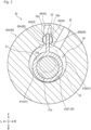
- the upper cylinder 40A and the lower cylinder 40B have a configuration substantially similar to each other. Therefore, hereinafter, the configuration of the cylinder 40 will be described mainly using the upper cylinder 40A illustrated in Figs. 2 and 3 .
- the cylinder chamber 41 illustrated in Figs. 1 and 2 is a space in which suction and compression of a refrigerant are performed.
- the cylinder chamber 41 is formed so as to penetrate, in the up-down direction, the central part in plan view of the cylinder 40.
- the cylinder chamber 41 has an upper end part and a lower end part substantially closed by the front head 31 and the middle plate 32 (see Fig. 1 ).
- the cylinder chamber 41 is partitioned into a high-pressure chamber 41A on a left side and a low-pressure chamber 41B on a right side by the piston 50 (blade 52).
- the high-pressure chamber 41A of the cylinder chamber 41 (the cylinder chamber 41 of the upper cylinder 40A) communicates with the discharge port 31b of the front head 31.
- the suction port 42 suctions the refrigerant into the cylinder chamber 41.
- the suction port 42 is formed so as to radially penetrate the cylinder 40.
- the suction port 42 is formed so as to communicate with the low-pressure chamber 41B of the cylinder chamber 41.
- a suction pipe (not illustrated) through which the refrigerant flows outside the casing 10 is connected to the suction port 42.
- the blade groove 43 illustrated in Figs. 2 and 3 is a part through which the blade 52 of the piston 50 described later is inserted.
- the blade groove 43 is formed at the central part in the left-right direction of a front part of the cylinder 40.
- the blade groove 43 is formed so as to be recessed forward from a front part on an inner surface of the cylinder chamber 41.
- the blade groove 43 includes a back pressure chamber 44 and a bush hole 45.
- the back pressure chamber 44 constitutes a main part of the blade groove 43.
- the back pressure chamber 44 is formed in a substantially rectangular shape elongated in the front-rear direction in plan view.
- the bush hole 45 is a part in which the bush 60 described later is accommodated.
- a pair of the bush holes 45 are formed so as to be recessed outward in the left-right direction in an intermediate part in the front-rear direction of the blade groove 43.
- the bush hole 45 is formed in a substantially semicircular shape in plan view.
- the pair of bush holes 45 have inner surfaces 45a facing each other.
- the inner surface 45a constitutes a curved surface recessed outward in the left-right direction.
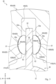
- the bush hole 45 on the left side is referred to as “high-pressure-side bush hole 45A”
- the bush hole 45 on the right side is referred to as “low-pressure-side bush hole 45B” (see Fig. 3 ).
- the configuration of the cylinder 40 has been described above with the upper cylinder 40A.
- the lower cylinder 40B is different from the upper cylinder 40A in being disposed between (lower side) the middle plate 32 and the rear head 33. Therefore, the cylinder chamber 41 of the lower cylinder 40B has an upper end part and a lower end part substantially closed by the middle plate 32 and the rear head 33 (see Fig. 1 ).
- the high-pressure chamber 41A of the cylinder chamber 41 of the lower cylinder 40B communicates with the discharge port 33b of the rear head 33.
- the lower cylinder 40B is configured substantially similarly to the upper cylinder 40A except for the point described above. That is, the shape of the lower cylinder 40B is substantially similar to the shape of the upper cylinder 40A.
- the piston 50 illustrated in Figs. 1 to 3 compresses the refrigerant in the cylinder chamber 41.
- the entire piston 50 is accommodated in the cylinder chamber 41 and the blade groove 43.
- the piston 50 compresses the refrigerant in the cylinder chamber 41.
- the thickness dimension (up-down dimension) of the piston 50 is formed substantially similarly to the thickness dimension (up-down dimension) of the cylinder 40.
- the piston 50 is provided in each of the upper cylinder 40A and the lower cylinder 40B.
- the upper and lower pistons 50 have a configuration substantially similar to each other. Therefore, hereinafter, the configuration of the piston 50 will be described mainly using the upper piston 50.
- the piston 50 includes a main body 51 and the blade 52.
- the main body 51 illustrated in Fig. 2 is a part accommodated in the cylinder chamber 41.
- the main body 51 is formed in a substantially cylindrical shape penetrating in the up-down direction.
- the outer diameter of the main body 51 is formed to be smaller than the inner diameter of the cylinder chamber 41.
- the main body 51 includes a shaft hole 51a.
- the shaft hole 51a is a part through which the first eccentric portion 23 of the drive shaft 21 is inserted.
- the shaft hole 51a is provided with the first eccentric portion 23 rotatably about the rotation central axis of the drive shaft 21. In a state where the first eccentric portion 23 is inserted into the shaft hole 51a, the main body 51 and the drive shaft 21 are coupled in a relatively rotatable state.
- the blade 52 is a part that protrudes in a radial direction (forward in Fig. 2 ) with respect to the main body 51.
- the blade 52 has at least a tip end part in a protruding direction inserted into the blade groove 43.
- the blade 52 is formed in a substantially rectangular shape in plan view.
- a width dimension (left-right dimension) of the blade 52 is formed smaller than a width dimension (left-right dimension) of the blade groove 43.
- the blade 52 partitions the inside of the cylinder chamber 41 into the high-pressure chamber 41A and the low-pressure chamber 41B together with the main body 51. With turning of the piston 50, the blade 52 moves forward and backward (reciprocates) through the blade groove 43 in the front-rear direction and rocks left and right.
- the blade 52 has left and right side surfaces 52a facing outward in the left-right direction.
- the side surface 52a is formed into a flat surface.
- the bush 60 illustrated in Figs. 2 to 7 slides with respect to the inner surface 45a of the bush hole 45 of the blade groove 43 and the side surface 52a of the blade 52.
- the bush 60 is formed in a substantially semi-columnar shape.
- the up-down dimension of the bush 60 is formed substantially similarly to the thickness dimension (up-down dimension) of the cylinder 40 and the piston 50.
- the bush 60 is formed in a shape symmetrical front and rear.
- the bush 60 (total of four) is accommodated in each of the pair of bush holes 45 (the high-pressure-side bush hole 45A and the low-pressure-side bush hole 45B) of the upper cylinder 40A and the lower cylinder 40B.
- the bush 60 rocks along the inner surface 45a of the bush hole 45 with rocking of the blade 52.
- the bush 60 accommodated in the high-pressure-side bush hole 45A is referred to as "high-pressure-side bush 60A”
- the bush 60 accommodated in the low-pressure-side bush hole 45B is referred to as "low-pressure-side bush 60B”.
- the high-pressure-side bush 60A and the low-pressure-side bush 60B have shapes similar to each other.
- the configuration of the bush 60 will be described using the low-pressure-side bush 60B.
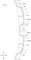
- the bush 60 includes a first sliding surface 61 and a second sliding surface 63.
- the first sliding surface 61 illustrated in Figs. 3 to 6 is a surface that slides with the inner surface 45a of the bush hole 45.
- the first sliding surface 61 is formed to bulge outward in the left-right direction.
- the first sliding surface 61 is formed in a curved surface shape having a substantially semicircular shape in plan view.
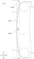
- the first sliding surface 61 includes a first bulge 62.
- the first bulge 62 illustrated in Figs. 4 and 6 is a part bulging radially outward on the first sliding surface 61. More specifically, the first bulge 62 bulges radially outward relative to another part (part where the first bulge 62 is not formed) of the first sliding surface 61.
- a pair of the first bulges 62 are provided so as to be positioned on both circumferential sides (both sides in the front-rear direction) in plan view of the first sliding surface 61.
- the pair of first bulges 62 are provided on a circumferential end part side (vicinity of the circumferential end part) in plan view of the first sliding surface 61.
- the pair of first bulges 62 are provided so as to be constantly in contact with the inner surface 45a regardless of the orientation of the bush 60 rocking in the bush hole 45 (see Fig. 8 ).
- the pair of first bulges 62 are formed in a shape symmetrical front and rear to each other.
- first bulge 62 on the front side anti-main body 51 side, radially outside of cylinder 40
- front-side first bulge 62A anti-main body 51 side, radially outside of cylinder 40
- rear-side first bulge 62B rear-side first bulge 62B
- the first sliding surface 61 (first bulge 62) is formed by appropriately performing cutting or the like on a part on the first sliding surface 61 side of the bush 60. That is, the first sliding surface 61 is formed by subjecting the bush 60 before processing to processing of removing the remaining part so as to form the first sliding surface 61.
- the first bulge 62 includes a first end part 62a, a second end part 62b, and a central part 62c.
- the first end part 62a illustrated in Fig. 6 constitutes an end part on the center side in the front-rear direction of the bush 60 (side on which the pair of first bulges 62 face each other) in the first bulge 62.
- the first end part 62a is formed in a curved surface shape such that a gap X between the first end part 62a and the inner surface 45a of the bush hole 45 gradually decreases toward the circumferential center side in plan view of the first bulge 62.
- the second end part 62b constitutes an end part on the anti-center side in the front-rear direction (side on which the pair of first bulges 62 is separated from each other) of the bush 60 in the first bulge 62.
- the second end part 62b is formed in a curved surface shape such that the gap X between the second end part 62b and the inner surface 45a of the bush hole 45 gradually decreases toward the circumferential center side in plan view of the first bulge 62.
- the second end part 62b constitutes a curved surface inclined more gently than the first end part 62a as a whole.
- the second end part 62b forms an S shaped curved surface in which a circumferential central part in plan view is steeper than other parts.
- the central part 62c constitutes a circumferential central part in plan view of the first bulge 62.
- the central part 62c is formed in a smooth curved surface shape having a relatively large radius of curvature.
- the radius of curvature of the central part 62c substantially the same value as the radius of curvature of the inner surface 45a of the bush hole 45 can be adopted.
- the radius of curvature of the central part 62c may have a value smaller than that of the radius of curvature of the inner surface 45a of the bush hole 45.
- the central part 62c (first bulge 62) is formed to have a height dimension H1 in a range of, for example, 2 to 5 pm.
- the height dimension H1 of the first bulge 62 is a distance between a vertex of the central part 62c and an imaginary line A constituting a curved surface in a case of assuming that the first bulge 62 is not formed on the first sliding surface 61.
- the second sliding surface 63 illustrated in Figs. 4 and 7 is a surface that slides with the side surface 52a of the blade 52.
- the second sliding surface 63 is formed so as to slightly bulge on the blade 52 side (left side in Fig. 7 ).
- the second sliding surface 63 includes a second bulge 64.
- the second bulge 64 is a part bulging on the blade 52 side (left side in Fig. 7 ) on the second sliding surface 63.
- the second bulge 64 is formed by appropriately performing cutting or the like on a part on the second sliding surface 63 side of the bush 60. That is, the second bulge 64 is formed by subjecting the bush 60 before processing to processing of removing the remaining part so as to form the second bulge 64.
- the second bulge 64 includes an end part 64a and a central part 64b.
- the end part 64a illustrated in Fig. 7 constitutes an end part on the front-rear direction end part side of the bush 60 in the second bulge 64.
- the end part 64a is formed in a curved surface shape having a relatively small radius of curvature.
- the end part 64a is formed in a curved surface shape such that the gap X between the end part 64a and the side surface 52a of the blade 52 gradually decreases toward the circumferential center side in plan view of the second sliding surface 63.
- the central part 64b constitutes a circumferential central part of the second bulge 64 in plan view.
- the central part 64b is formed in a curved surface shape having a relatively large radius of curvature with the circumferential central part in plan view as a vertex.
- the radius of curvature of the central part 64b is formed to be larger than the radius of curvature of the end part 64a.
- the central part 64b is formed in a curved surface shape such that the gap X between the central part 64b and the side surface 52a of the blade 52 gradually decreases toward the circumferential center side in plan view of the second sliding surface 63.
- the central part 64b is formed to have a height dimension H2 in a range of, for example, 2 to 5 pm.
- the height dimension H2 of the second bulge 64 is a distance from an imaginary line C connecting respective contact points of a pair of imaginary lines B constituting a circle having the radius of curvature of the end part 64a and the central part 64b to the vertex of the central part 64b.
- the piston 50 (main body 51) turns (rotates) clockwise in plan view in the cylinder chamber 41 of the cylinder 40 (upper cylinder 40A) with rotation of the first eccentric portion 23 of the drive shaft 21.
- the volume of the low-pressure chamber 41B on the right side of the cylinder chamber 41 increases, whereby the refrigerant from the suction pipe (not illustrated) is suctioned into the cylinder chamber 41 through the suction port 42.
- the volume decreases on the left side of the cylinder chamber 41, thereby forming the high-pressure chamber 41A that compresses the suctioned refrigerant. Note that at this time, since the volume increases in the low-pressure chamber 41B on the right side of the cylinder chamber 41, a new refrigerant is suctioned into the low-pressure chamber 41B.
- the discharge valve (not illustrated) of the discharge port 31b of the front head 31 is opened by the pressure of the refrigerant, and the refrigerant is discharged into the casing 10 through the discharge port 31b.
- the refrigerant discharged into the casing 10 is fed into the refrigerant circuit (not illustrated) through the discharge pipe (not illustrated).
- the compression mechanism 30 compresses the refrigerant in the cylinder chamber 41 by the turning of the piston 50.
- the blade 52 in the blade groove 43 moves forward and backward and rocks left and right.
- the bush 60 slides with respect to the inner surface 45a of the bush hole 45 and the side surface 52a of the blade 52.
- the inside of the back pressure chamber 44 of the cylinder 40 is increased in pressure by the refrigerant in the casing 10 and is filled with the lubricant Y that circulates in the refrigerant circuit together with the refrigerant.
- An oil film by the lubricant Y drawn from the back pressure chamber 44 is formed between the bush 60 and a member (the inner surface 45a of the bush hole 45 and the side surface 52a of the blade 52) that becomes a sliding target of the bush 60.
- the gap X due to the second bulge 64 is formed between the second sliding surface 63 of the bush 60 and the side surface 52a of the blade 52.
- the gap X is formed so as to gradually decrease (in a wedge shape) toward the circumferential center side in plan view of the second sliding surface 63.
- the lubricant Y is drawn into the circumferential center side in plan view of the second sliding surface 63 (second bulge 64).
- a wedge effect can promote the formation of an oil film between the second sliding surface 63 and the side surface 52a of the blade 52.
- the lubricant Y between the second sliding surface 63 and the side surface 52a is drawn into the circumferential center side (front side) in plan view of the second sliding surface 63 along with the movement of the blade 52.
- the gap X having a wedge shape described above is formed between the second sliding surface 63 and the side surface 52a, the formation of the oil film between the second sliding surface 63 and the side surface 52a can be effectively promoted by the wedge effect. This can generate oil film pressure between the second sliding surface 63 and the side surface 52a, and can suppress generation of galling and seizure.
- the lubricant Y between the second sliding surface 63 and the side surface 52a is drawn into the circumferential center side (rear side) in plan view of the second sliding surface 63 similarly to the above along with the movement of the blade 52.
- the wedge effect due to the gap X between the second sliding surface 63 and the side surface 52a can effectively promote the formation of the oil film between the second sliding surface 63 and the side surface 52a, and can suppress generation of galling and seizure.
- the blade 52 rocks in the left-right direction.
- the bush 60 rocks along the inner surface 45a of the bush hole 45 in a state of being accommodated in the bush hole 45.
- the first sliding surface 61 of the bush 60 slides in the circumferential direction in plan view between the inner surface 45a of the bush hole 45 and the inner surface 45a (first sliding surface 61).
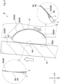
- the gap X by the first bulge 62 is formed between the first sliding surface 61 of the bush 60 and the inner surface 45a of the bush hole 45.
- the gap X is formed so as to gradually decrease (in a wedge shape) toward the circumferential center side in plan view of the first bulge 62. Due to the bush 60 and the bush hole 45 circumferentially sliding in this state, the lubricant Y is drawn into the circumferential center side in plan view of the first bulge 62. At this time, a wedge effect can promote the formation of an oil film between the first sliding surface 61 and the inner surface 45a of the bush hole 45.
- the lubricant Y between the first sliding surface 61 and the inner surface 45a is drawn into the circumferential center side in plan view of the first bulge 62 along with the rocking of the bush 60.
- the gap X having a wedge shape described above is formed between the rear-side first bulge 62B (the second end part 62b and the central part 62c) of the first sliding surface 61 and the inner surface 45a.
- the gap X having a wedge shape is similarly formed also between the front-side first bulge 62A (the first end part 62a and the central part 62c) and the inner surface 45a. Due to this, the wedge effect of the gap X can effectively promote the formation of the oil film between the first sliding surface 61 and the inner surface 45a. This can generate oil film pressure between the first sliding surface 61 and the inner surface 45a, and can suppress generation of galling and seizure.
- the lubricant Y between the first sliding surface 61 and the inner surface 45a is drawn toward the circumferential center side in plan view of the first bulge 62 along with the rocking of the bush 60 similarly to the above.
- the gap X having a wedge shape is formed between the rear-side first bulge 62B (the first end part 62a and the central part 62c) of the first sliding surface 61 and the inner surface 45a.
- the gap X having a wedge shape is similarly formed also between the front-side first bulge 62A (the second end part 62b and the central part 62c) and the inner surface 45a. Due to this, the wedge effect of the gap X can effectively promote the formation of the oil film between the first sliding surface 61 and the inner surface 45a, and can suppress generation of galling and seizure.
- the pair of first bulges 62 are provided so as to be positioned on both circumferential end sides in plan view of the first sliding surface 61 of the bush 60. This can effectively promote the formation of the oil film on both circumferential end sides in plan view of the first sliding surface 61 of the bush 60.
- forming the rear-side first bulge 62B can effectively promote the formation of the oil film on the main body 51 side (inner side) of the piston 50 that is relatively far from the back pressure chamber 44 and where the oil film is easily broken.
- the inclination of the curved surface of the first end part 62a is formed steeper than that of the second end part 62b. This makes it easy to hold the lubricant Y between the pair of first bulges 62.
- the bush 60 is formed in a shape symmetrical front and rear. This can suppress the bush 60 from being assembled with a wrong orientation when the bush 60 is assembled to the bush hole 45.
- the first bulge 62 and the second bulge 64 that generate the wedge effect are formed in the bush 60.
- the position of the gap X having a wedge shape with respect to the inner surface 45a of the bush hole 45 moves with rocking of the bush 60. Due to this, an oil film can be formed at a part to which a load is easily applied along with the rocking of the bush 60, and the wedge effect can be effectively generated. In this manner, the wedge effect can be generated with reference to the position of the bush 60.
- the front-side first bulge 62A and the rear-side first bulge 62B have curved surface shapes different from each other on both sides in the circumferential direction in plan view (see the first end part 62a and the second end part 62b). This can provide a difference in the degree of generation of the wedge effect depending on the ease of application of the load to the sliding portion.
- the bush 60 illustrated in Fig. the bush 60 illustrated in Fig.
- the configurations (shape, height, and the like) of the first bulge 62 and the second bulge 64 are not limited to those described above.
- first end part 62a and the second end part 62b of the first bulge 62 may be interchanged. That is, the first bulge 62 may be reversed front and rear.
- the shapes of the first end part 62a and the second end part 62b of the first bulge 62 are different from each other, but the present invention is not limited to such aspect.
- the first end part 62a and the second end part 62b of the first bulge 62 may have the shape same as each other. That is, the first bulge 62 may be formed in a shape symmetrical front and rear.
- a recess functioning as an oil reservoir may be formed at a predetermined position (e.g., vertex) of the first bulge 62 and the second bulge 64. This can suppress the oil film from breaking by holding the lubricant Y in the recess, and can suppress generation of galling and seizure.
- the configurations of the first bulge 62 and the second bulge 64 are not limited to those in the above-described example, and can be appropriately changed from the viewpoint of effectively promoting the formation of an oil film.
- the compression mechanism 30 includes: the cylinder 40 including the cylinder chamber 41 and the blade groove 43 communicating with the cylinder chamber 41; the piston 50 including the blade 52 that partitions the cylinder chamber 41 into the high-pressure chamber 41A and the low-pressure chamber 41B and is inserted into the blade groove 43 so as to be movable forward and backward, the piston 50 turnably provided in the cylinder chamber 41; and the bush 60 rockably accommodated in the bush hole 45 formed in the blade groove 43 and including the first sliding surface 61 that slides with the inner surface 45a of the bush hole 45 and the second sliding surface 63 that slides with the side surface 52a of the blade, in which the compression mechanism 30 includes at least one of the first oil film formation portion (first bulge 62) formed on one of the first sliding surface 61 and the inner surface 45a such that the gap X between the first sliding surface 61 and the inner surface 45a gradually decreases toward a direction in which the lubricant Y is drawn between the first sliding surface 61 and the inner surface 45a along with rock
- Such configuration can suppress galling and seizure. That is, by providing the first oil film formation portion (first bulge 62) or the second oil film formation portion (second bulge 64), due to the wedge effect, the lubricant Y can be gradually easily introduced between the first sliding surface 61 and the inner surface 45a or between the second sliding surface 63 and the side surface 52a. This effectively promotes formation of an oil film between the bush 60 and the bush hole 45 or between the bush 60 and the blade 52, and can suppress galling and seizure.
- the first oil film formation portion (first bulge 62) is formed so as to bulge on the inner surface 45a side on the first sliding surface 61.
- the first oil film formation portion (first bulge 62) formed so as to bulge on the first sliding surface 61 of the bush 60 can promote the formation of an oil film. Since the bush 60 is provided with the first oil film formation portion (first bulge 62), it is possible to promote the formation of the oil film regardless of the position of the bush 60 with respect to the sliding object (bush hole 45) of the bush 60.
- Both the first oil film formation portion (first bulge 62) and the second oil film formation portion (second bulge 64) are included.
- Such configuration can effectively promote the formation of oil films on both the first sliding surface 61 and the second sliding surface 63 of the bush 60. That is, providing both the first oil film formation portion (first bulge 62) and the second oil film formation portion (second bulge 64) can effectively promote the formation of oil films between the bush 60 and the bush hole 45 and between the bush 60 and the blade 52.
- the second oil film formation portion (second bulge 64) is formed so as to bulge on the side surface 52a side on the second sliding surface 63.
- the second oil film formation portion (second bulge 64) formed so as to bulge on the second sliding surface 63 of the bush 60 can promote the formation of an oil film. Since the bush 60 is provided with the second oil film formation portion (second bulge 64), it is possible to promote the formation of the oil film regardless of the position of the bush 60 with respect to the sliding object (blade 52) of the bush 60.
- the pair of first oil film formation portions (first bulges 62) are formed so as to be positioned on both end sides in a sliding direction of the first sliding surface 61 (both end sides in the circumferential direction in plan view of the first sliding surface 61).
- Such configuration can promote the formation of an oil film on both end sides in the sliding direction of the first sliding surface 61. That is, forming a pair of the first oil film formation portions (first bulges 62) so as to be positioned on both end sides in the sliding direction of the first sliding surface 61 can promote the formation of an oil film on both end sides in the sliding direction of the first sliding surface 61.
- the first oil film formation portion (the rear-side first bulge 62B) formed on the main body 51 side of the piston 50 where the oil film is easily broken can promote the formation of the oil film in a part where the oil film is easily broken.
- first bulge 62 is an embodiment of the first oil film formation portion.
- the second bulge 64 is an embodiment of the second oil film formation portion.
- the shape of the first sliding surface 61 of the bush 60 may be the same as that of the second embodiment illustrated in Fig. 11 .
- the first sliding surface 61 is formed of a curved surface having a different radius of curvature, whereby the gap X having a wedge shape is formed between the first sliding surface 61 and the inner surface 45a of the bush hole 45.
- the configuration of the first sliding surface 61 of the bush 60 according to the second embodiment will be described with the low-pressure-side bush 60B.
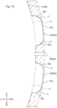
- the first sliding surface 61 has a sliding curved surface portion 61a, a central curved surface portion 61b, a rear curved surface portion 61c, and a front curved surface portion 61d.
- the sliding curved surface portion 61a is a part curved along the sliding direction (circumferential direction) of the bush 60 in plan view.
- the sliding curved surface portion 61a has a curved surface shape (arc shape) in plan view formed in a curved surface shape having a radius R1 of curvature substantially the same as the radius of curvature of the bush hole 45.
- a pair of the sliding curved surface portions 61a are provided at intervals so as to be positioned on both sides in the circumferential direction (both sides in the front-rear direction) in plan view of the first sliding surface 61. Note that in Fig. 11 , the first sliding surface 61 is indicated by a thick line.
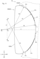
- the center in plan view of the bush hole 45 (arc center of the first sliding surface 61) is indicated by a point P1.
- the point P1 is located on an imaginary line L1 along the height direction of the bush 60 (the line direction connecting the vertex of the first sliding surface 61 and the vertex of the second sliding surface 63) in plan view.
- the height direction of the bush 60 is oriented in the left-right direction.
- the central curved surface portion 61b is a part circumferentially adjacent to the pair of sliding curved surface portions 61a between the pair of sliding curved surface portions 61a.
- the central curved surface portion 61b has a curved surface shape (arc shape) in plan view formed in a curved surface shape having a radius R2 of curvature larger than the radius of curvature (radius R1 of curvature) of the bush hole 45.
- the arc center of the central curved surface portion 61b is indicated by a point P2.
- the point P2 is located leftward relative to the point P1 on the imaginary line L1.
- the rear curved surface portion 61c is a part adjacent circumferentially to a rear part of the sliding curved surface portion 61a on the rear side.
- the rear curved surface portion 61c has a curved surface shape (arc shape) in plan view formed in a curved surface shape having a radius R3 of curvature larger than the radius of curvature (radius R1 of curvature) of the bush hole 45.
- the radius R3 of curvature is formed larger than the radius R2 of curvature.
- the arc center of the rear curved surface portion 61c is indicated by a point P3.
- the point P3 is located forward relative to the point P1 on an imaginary line L2 passing through the point P1 and orthogonal to the imaginary line L1.
- the front curved surface portion 61d is a part adjacent circumferentially to a front part of the sliding curved surface portion 61a on the front side.
- the front curved surface portion 61d has a curved surface shape (arc shape) in plan view formed in a curved surface shape having a radius R4 of curvature larger than the radius of curvature (radius R1 of curvature) of the bush hole 45.
- the radius R4 of curvature is formed to have the same size as the radius R3 of curvature.
- the arc center of the front curved surface portion 61d is indicated by a point P4.
- the point P4 is located rearward relative to the point P1 on the imaginary line L2.
- the gap X between the first sliding surface 61 and the inner surface 45a can be gradually decreased from the curved surface portion (the central curved surface portion 61b, the rear curved surface portion 61c, and the front curved surface portion 61d) having a relatively large radius of curvature toward the adjacent sliding curved surface portion 61a. Due to this, substantially similarly to the bush 60 according to the first embodiment, the wedge effect of the gap X can effectively promote the formation of the oil film between the first sliding surface 61 and the inner surface 45a, and can suppress generation of galling and seizure.
- the present embodiment it is possible to secure a relatively large sliding area with respect to the inner surface 45a in the sliding curved surface portion 61a. According to the present embodiment, it is possible to relatively reduce the processing amount (the amount of the part to be removed from the bush 60 before processing) in a case of forming the first sliding surface 61 by cutting or the like, and to relatively easily form the sliding curved surface portion 61a.
- the radius R1 of curvature is formed to be substantially the same as the radius of curvature of the bush hole 45
- the present invention is not limited to such aspect.
- the radius R1 of curvature may be formed to be smaller than the radius of curvature of the bush hole 45.
- the radius R1 of curvature may be formed to be larger than the radius of curvature of the bush hole 45.
- the radii R3 and R4 of curvature are formed larger than the radius R2 of curvature has been described, but the present invention is not limited to such aspect.
- the radii R3 and R4 of curvature may be formed to be smaller than the radius R2 of curvature, and the radii R2, R3, and R4 of curvature may be formed to have the same size as one another.
- the positions of the points P1 to 4 in the present embodiment are an example, and as the positions of the points P1 to 4, an appropriate position can be set within a range in which the gap X having a wedge shape can be formed between the first sliding surface 61 and the inner surface 45a.
- the first sliding surface 61 includes the first curved surface portion (the sliding curved surface portion 61a) curved along the sliding direction and the second curved surface portion (the central curved surface portion 61b, the rear curved surface portion 61c, and the front curved surface portion 61d) adjacent in the sliding direction to the first curved surface (the sliding curved surface portion 61a), and the first oil film formation portion (the sliding curved surface portion 61a, the central curved surface portion 61b, the rear curved surface portion 61c, and the front curved surface portion 61d) is formed on the first sliding surface 61 by making the radius of curvature of the second curved surface portion (the central curved surface portion 61b, the rear curved surface portion 61c, and the front curved surface portion 61d) larger than the radius of curvature of the first curved surface (the sliding curved surface portion 61a).
- Such configuration can relatively easily form the first oil film formation portion (sliding curved surface portion 61a, central curved surface portion 61b, rear curved surface portion 61c, and front curved surface portion 61d). That is, it is possible to relatively reduce the processing amount (the amount of the part to be removed from the bush 60 before processing) in a case of forming the first oil film formation portion (the sliding curved surface portion 61a, the central curved surface portion 61b, rear curved surface portion 61c, and the front curved surface portion 61d) by cutting or the like.
- the present invention is not limited to such aspect.
- the first bulge 62 may be formed on the bush hole 45 side of the cylinder 40.
- the first bulge 62 is formed so as to bulge on the bush 60 side on the inner surface 45a of the bush hole 45.
- the pair of first bulges 62 are formed so as to be positioned on both circumferential end sides in plan view of the inner surface 45a is given.
- As the shape of the first bulge 62 a similar shape to the first bulge 62 according to the first embodiment can be adopted.
- the gap X having a wedge shape by the first bulge 62 is formed between the first sliding surface 61 of the bush 60 and the inner surface 45a of the bush hole 45. Therefore, due to the bush 60 circumferentially sliding, the lubricant Y is drawn to the circumferential center side in the plan view of the first bulge 62, and the wedge effect can promote the formation of the oil film between the first sliding surface 61 and the inner surface 45a of the bush hole 45.
- the above-described compression mechanism 30A also achieves substantially similar effects to those by the compression mechanism 30 according to the first embodiment.
- the first bulge 62 is provided on the bush hole 45 side that is the sliding target of the bush 60.
- the first bulge 62 in a predetermined part, to which a load of the bush 60 is easily applied, within the bush hole 45, it is possible to effectively form an oil film in the predetermined part to which a load is easily applied.
- a recess 45b that generates a wedge effect may be formed on the bush hole 45 side of the cylinder 40.
- the recess 45b is formed so as to be recessed on the inner surface 45a of the bush hole 45.
- a shape corresponding to the first bulge 62 according to the first embodiment can be adopted.
- the gap X having a wedge shape by the recess 45b is formed between the first sliding surface 61 of the bush 60 and the inner surface 45a of the bush hole 45. Therefore, when the bush 60 slides in the circumferential direction in plan view, the lubricant Y is drawn, and the wedge effect can promote the formation of the oil film between the first sliding surface 61 and the inner surface 45a of the bush hole 45.
- the above-described compression mechanism 30B also achieves substantially similar effects to those by the compression mechanism 30 according to the first embodiment.
- the compression mechanism 30B by performing processing of denting a part of the inner surface 45a of the bush hole 45 (e.g., cutting processing), it is possible to relatively easily form the recess 45b that generates the wedge effect.
- the recess 45b may be formed on the first sliding surface 61 of the bush 60.
- the first oil film formation portion (recess 45b) is formed to be recessed in the inner surface 45a.
- Such configuration can relatively easily form the first oil film formation portion (recess 45b). That is, by performing processing of denting a part of the inner surface 45a of the bush hole 45 (e.g., cutting processing), it is possible to relatively easily form the first oil film formation portion (recess 45b).
- the recess 45b is an embodiment of the first oil film formation portion.
- the pair of first oil film formation portions (the first bulge 62, the recess 45b) are provided so as to be positioned on both end sides in the circumferential direction in plan view of the first sliding surface 61 of the bush 60 has been described, but the present invention is not limited to such configuration.
- the first oil film formation portion (the first bulge 62, the recess 45b) may be provided only on one side in the circumferential direction in plan view of the first sliding surface 61.
- the first oil film formation portion (the first bulge 62, the recess 45b) may be provided on the main body 51 side (rear side) of the piston 50 that is relatively far from the back pressure chamber 44 and where the oil film is easily broken.
- an appropriate oil passage for guiding the lubricant Y from the back pressure chamber 44 of the blade groove 43 may be formed on the anti-main body 51 side (inner side) on the first sliding surface 61.
- the number and positions of the first oil film formation portion (the first bulge 62, the recess 45b, the sliding curved surface portion 61a, the central curved surface portion 61b, the rear curved surface portion 61c, and the front curved surface portion 61d) and the second oil film formation portion (the second bulge 64) of the bush 60 are not limited to the examples described in the above embodiments.
- the number and positions of the first oil film formation portions (the first bulge 62, the recess 45b, and the like) and the second oil film formation portion (the second bulge 64) can be appropriately set from the viewpoint of effectively promoting the formation of an oil film.
- both of the pair of bushes 60 are provided with the first oil film formation portion (the first bulge 62, the recess 45b, and the like)
- the present invention is not limited to such configuration.
- one of the pair of bushes 60 may be provided with the first oil film formation portion (the first bulge 62, the recess 45b, and the like).
- the first oil film formation portion (the first bulge 62, the recess 45b, and the like) may be provided on the low-pressure-side bush 60B (or the low-pressure-side bush hole 45B) side where the sliding resistance tends to become large by the action of the load due to the pressure difference between the high-pressure chamber 41A and the low-pressure chamber 41B in the cylinder chamber 41.
- the second oil film formation portion may also be provided on one of the pair of bushes 60 (e.g., the low-pressure-side bush 60B).
- first oil film formation portion the first bulge 62, the recess 45b, and the like
- second oil film formation portion the second bulge 64
- pressing, polishing, or the like can be adopted.
- the blade groove 43 (back pressure chamber 44) is formed in a substantially rectangular shape in plan view
- the present invention is not limited to such configuration.
- the blade groove 43 (back pressure chamber 44) may be formed in a circular shape (cylindrical shape) in plan view.
- the first oil film formation portions (the first bulge 62, the recess 45b, and the like) of the above embodiments (first to fourth embodiments) may be appropriately combined and applied to the bush 60 or the bush hole 45.
- the first bulge 62 (see Fig. 8 ) of the first embodiment may be applied to the first oil film formation portion on the front side of one of the bushes 60
- the first bulge 62 (see Fig. 12 ) of the third embodiment may be applied to the first oil film formation portion on the rear side of the bush hole 45 sliding with the bush 60.
- the compression mechanism 30 includes the two cylinders 40 arranged in parallel up and down, but the present invention is not limited to such configuration, and the compression mechanism may include one cylinder 40.
- the compressor 1 can be used for, for example, an air conditioner for a vehicle (automobile), a railway, or a business.
- the present invention can be applied to a compression mechanism.
Landscapes
- Engineering & Computer Science (AREA)
- Mechanical Engineering (AREA)
- General Engineering & Computer Science (AREA)
- Manufacturing & Machinery (AREA)
- Applications Or Details Of Rotary Compressors (AREA)
Abstract
Description
- The present invention relates to a technique of a compression mechanism.
- Conventionally, a technique of a compression mechanism is known. For example, Patent Literature 1 discloses such technique.
- Patent Literature 1 discloses a compression mechanism that compresses a refrigerant by causing a piston provided in a cylinder chamber to perform turning motion. The piston of the compression mechanism is provided with a blade that partitions the cylinder chamber into a suction chamber (low-pressure chamber) and a compression chamber (high-pressure chamber), and the cylinder chamber is provided with a blade groove through which the blade is inserted so as to freely reciprocate. Bushes (high-pressure-side bush and low-pressure-side bush) are provided between both side surfaces of the blade and the blade groove. The blade groove is provided with a bush hole in which the bush is rockably accommodated. The bush slides with respect to the side surface of the blade and the bush hole with motion of the piston.
- Here, to the low-pressure-side bush is applied a load due to a pressure difference between the high-pressure side and the low-pressure side in the cylinder chamber. Due to this, it is conceivable that sliding resistance of the low-pressure-side bush becomes relatively large.
- In the invention described in Patent Literature 1, a sliding surface of the low-pressure-side bush is provided with an introduction groove for guiding the refrigerant in the blade groove. Introduction of the refrigerant into the introduction groove causes, in the low-pressure-side bush, a load acting in a direction opposite to the load generated by the sliding resistance. This can reduce the sliding resistance of the low-pressure-side bush.
- However, in the bush described in Patent Literature 1, the sliding resistance cannot be reduced in a part not provided with the introduction groove, and galling and seizure may occur in the part. Therefore, a compression mechanism that can suppress generation of galling and seizure is required.
- Patent Literature 1:
Japanese Patent Application Laid-Open No. 2005-315112 - The present invention has been made in view of the above circumstances, and an object of the present invention is to provide a compression mechanism that can suppress generation of galling and seizure.
- The problem to be solved by the present invention is as described above, and a means for solving this problem will be described below.
- That is, a compression mechanism of the present invention includes: a cylinder including a cylinder chamber and a blade groove communicating with the cylinder chamber; a piston including a blade that partitions the cylinder chamber into a high-pressure chamber and a low-pressure chamber and is inserted into the blade groove so as to be movable forward and backward, the piston turnably provided in the cylinder chamber; and a bush rockably accommodated in a bush hole formed in the blade groove and including a first sliding surface that slides with an inner surface of the bush hole and a second sliding surface that slides with a side surface of the blade, in which the compression mechanism includes at least one of a first oil film formation portion formed on one of the first sliding surface and the inner surface such that a gap between the first sliding surface and the inner surface gradually decreases toward a direction in which lubricant is drawn between the first sliding surface and the inner surface along with rocking of the bush, and a second oil film formation portion formed on the second sliding surface such that a gap between the second sliding surface and the side surface gradually decreases toward a direction in which lubricant is drawn between the second sliding surface and the side surface along with forward and backward movement of the blade.
- The first oil film formation portion is formed so as to bulge on the inner surface side on the first sliding surface.
- The first sliding surface includes a first curved surface portion curved along a sliding direction, and a second curved surface portion adjacent in the sliding direction to the first curved surface, and the first oil film formation portion is formed on the first sliding surface by making a radius of curvature of the second curved surface portion larger than a radius of curvature of the first curved surface.
- The first oil film formation portion is formed so as to recess on the inner surface.
- Both the first oil film formation portion and the second oil film formation portion are included.
- The second oil film formation portion is formed so as to bulge on the side surface side on the second sliding surface.
- A pair of the first oil film formation portions are formed so as to be positioned on both end sides in a sliding direction of the first sliding surface.
- The present invention achieves the following effects.
- The compression mechanism of the present invention can suppress galling and seizure.
- In the compression mechanism of the present invention, the first oil film formation portion formed so as to bulge on the first sliding surface of the bush can promote the formation of an oil film.
- The compression mechanism of the present invention can relatively easily form the first oil film formation portion.
- The compression mechanism of the present invention can effectively promote the formation of oil films on both the first sliding surface and the second sliding surface of the bush.
- In the compression mechanism of the present invention, the second oil film formation portion formed so as to bulge on the second sliding surface of the bush can promote the formation of an oil film.
- The compression mechanism of the present invention can promote the formation of an oil film on both end sides in the sliding direction of the first sliding surface.
-
-
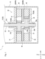
Fig. 1 is a side cross-sectional view illustrating a compressor including a compression mechanism according to a first embodiment of the present invention. -
Fig. 2 is a plan cross-sectional view illustrating the compression mechanism. -
Fig. 3 is an enlarged plan cross-sectional view illustrating the compression mechanism. -
Fig. 4 is a plan view illustrating a bush. -
Fig. 5 is a perspective view illustrating the bush. -
Fig. 6 is an enlarged plan view illustrating a first sliding surface of the bush. -
Fig. 7 is an enlarged plan view illustrating a second sliding surface of the bush. -
Fig. 8 is an enlarged plan cross-sectional view illustrating operation of the compression mechanism in a case where the bush rocks backward as a blade moves forward. -
Fig. 9 is an enlarged plan cross-sectional view illustrating operation of the compression mechanism in a case where the bush rocks forward as a blade moves backward. -
Fig. 10 is an enlarged plan view illustrating a modification of the first sliding surface. -
Fig. 11 is an enlarged plan view illustrating a bush of a compression mechanism according to a second embodiment of the present invention. -
Fig. 12 is an enlarged plan cross-sectional view illustrating operation of a compression mechanism according to a third embodiment of the present invention. -
Fig. 13 is an enlarged plan cross-sectional view illustrating operation of a compression mechanism according to a fourth embodiment of the present invention. - DESCRIPTION OF EMBODIMENTS
- In the following, description will be given with directions indicated by arrows U, D, F, B, L, and R in the drawings defined as an upward direction, a downward direction, a forward direction, a backward direction, a leftward direction, and a rightward direction, respectively. Note that the drawings used in the following description are schematic views, and dimensions and the like of each part are appropriately exaggerated for convenience of description.
- First, an outline of a compressor 1 provided with a
compression mechanism 30 according to the first embodiment of the present invention will be described with reference toFigs. 1 and2 . - The compressor 1 compresses a refrigerant. The compressor 1 is used, for example, in a household air conditioner or the like. The compressor 1 compresses and discharges the suctioned refrigerant by driving the
compression mechanism 30 by the driving force of amotor 20 provided in acasing 10. Note that thecompression mechanism 30 will be described in detail later. - The refrigerant compressed by the compressor 1 circulates in a refrigerant circuit (not illustrated). As the refrigerant, various refrigerants (e.g., refrigerant gas) used in an air conditioner or the like can be adopted. Lubricant Y (see
Fig. 8 ) used for lubrication of thecompression mechanism 30 circulates in the refrigerant circuit together with the refrigerant. The compressor 1 includes thecasing 10 and thecompression mechanism 30. - The
casing 10 illustrated inFig. 1 accommodates thecompression mechanism 30. The inside of thecasing 10 is a sealed space. Thecasing 10 is provided with a suction pipe (not illustrated) for sucking the refrigerant into thecompression mechanism 30 and a discharge pipe (not illustrated) for discharging the refrigerant discharged from thecompression mechanism 30 into thecasing 10. - Next, the configuration of the
compression mechanism 30 will be described in detail with reference toFigs. 1 to 7 . - By being driven by the driving force of the
motor 20, thecompression mechanism 30 compresses the suctioned refrigerant. Thecompression mechanism 30 constitutes a so-called rotary compression mechanism that compresses the refrigerant suctioned into acylinder chamber 41 of acylinder 40 by turning motion of apiston 50. As illustrated inFig. 1 , thecompression mechanism 30 includes twocylinders 40 vertically parallel to each other and thepiston 50. Thecompression mechanism 30 includes themotor 20, afront head 31, amiddle plate 32, a rear head 33, thecylinder 40, thepiston 50, and abush 60. - The
motor 20 illustrated inFigs. 1 and2 constitutes a drive source of thecompression mechanism 30. Themotor 20 has adrive shaft 21 that rotates about a central axis whose axial direction is facing the up-down direction. Themotor 20 is accommodated in thecasing 10 such that thedrive shaft 21 protrudes downward. Note that for convenience of description, the rotation phase of thedrive shaft 21 is different betweenFig. 1 andFig. 2 and the subsequent drawings. Thedrive shaft 21 includes amain shaft portion 22, a firsteccentric portion 23, and a secondeccentric portion 24. - The
main shaft portion 22 is a main structural body of thedrive shaft 21. Themain shaft portion 22 is formed in a substantially columnar shape with the axial direction facing the up-down direction. - The central axis of the first
eccentric portion 23 is eccentric with respect to the central axis of the main shaft portion 22 (drive shaft 21). Specifically, the central axis of the firsteccentric portion 23 is eccentric in a direction (leftward inFig. 1 ) orthogonal to the central axis of themain shaft portion 22. The firsteccentric portion 23 is formed in a substantially columnar shape having an enlarged diameter with respect to themain shaft portion 22. The firsteccentric portion 23 is formed in an intermediate part in the up-down direction of themain shaft portion 22. - The central axis of the second
eccentric portion 24 is eccentric in a direction different from the firsteccentric portion 23 with respect to the central axis of the main shaft portion 22 (drive shaft 21). Specifically, the central axis of the secondeccentric portion 24 is eccentric in a direction (rightward inFig. 1 ) opposite to the firsteccentric portion 23. The firsteccentric portion 23 is formed in a substantially columnar shape substantially similar to that of the firsteccentric portion 23. The secondeccentric portion 24 is formed low relative to the firsteccentric portion 23 in an intermediate part in the up-down direction of themain shaft portion 22. - The
front head 31 illustrated inFig. 1 constitutes an upper part of thecompression mechanism 30. Thefront head 31 is formed in a substantially plate shape with a plate surface facing the up-down direction. Thefront head 31 has an opening not illustrated, and partitions the inside of thecasing 10 in a state of communicating up and down. Thefront head 31 includes aninsertion hole 31a and adischarge port 31b. - The
insertion hole 31a is a part through which themain shaft portion 22 of thedrive shaft 21 is inserted. Theinsertion hole 31a is formed so as to penetrate, in the up-down direction, the central part in plan view of thefront head 31. Theinsertion hole 31a rotatably supports themain shaft portion 22. - The
discharge port 31b is a part from which the refrigerant compressed by the cylinder 40 (upper cylinder 40A) is discharged. Thedischarge port 31b is formed so as to penetrate, in the up-down direction, a part radially outside (left side) relative to theinsertion hole 31a in thefront head 31. Thedischarge port 31b communicates between thecylinder chamber 41 described later of theupper cylinder 40A and the inside of thecasing 10. Thedischarge port 31b is provided with an appropriate discharge valve (not illustrated) that opens and closes thedischarge port 31b. - The
middle plate 32 separates upper and lower cylinders 40 (upper cylinder 40A andlower cylinder 40B described later). Themiddle plate 32 is disposed below thefront head 31 across the cylinder 40 (upper cylinder 40A). Themiddle plate 32 includes aninsertion hole 32a. - The
insertion hole 32a is a part through which themain shaft portion 22 of thedrive shaft 21 is inserted. Theinsertion hole 32a is formed so as to penetrate, in the up-down direction, the central part in plan view of themiddle plate 32. - The rear head 33 constitutes a lower part of the
compression mechanism 30. The rear head 33 is disposed below themiddle plate 32 across the cylinder 40 (lower cylinder 40B). The rear head 33 is formed in a substantially plate shape with a plate surface facing the up-down direction. The rear head 33 includes aninsertion hole 33a and adischarge port 33b. - The
insertion hole 33a is a part through which themain shaft portion 22 of thedrive shaft 21 is inserted. Theinsertion hole 33a is formed so as to penetrate, in the up-down direction, the central part in plan view of the rear head 33. Theinsertion hole 33a rotatably supports themain shaft portion 22. - The
discharge port 33b is a part from which the refrigerant compressed by the cylinder 40 (lower cylinder 40B) is discharged. Thedischarge port 33b is formed so as to penetrate, in the up-down direction, a part radially outside (left side) relative to theinsertion hole 33a in the rear head 33. Thedischarge port 33b communicates between thecylinder chamber 41 described later of thelower cylinder 40B and the inside of thecasing 10. Thedischarge port 33b is provided with an appropriate discharge valve (not illustrated) that opens and closes thedischarge port 33b. - In the
cylinder 40 illustrated inFigs. 1 to 3 , suction and compression of a refrigerant by thepiston 50 are performed. Thecylinder 40 is formed in a substantially cylindrical shape penetrating in the up-down direction. In the present embodiment, as illustrated inFig. 1 , thecylinders 40 are disposed between (upper side) thefront head 31 and themiddle plate 32 and between (lower side) themiddle plate 32 and the rear head 33. Hereinafter, in a case where the upper andlower cylinders 40 are distinguished, theupper cylinder 40 is referred to as "upper cylinder 40A", and thelower cylinder 40 is referred to as "lower cylinder 40B". Thecylinder 40 includes thecylinder chamber 41, asuction port 42, and ablade groove 43. - The
upper cylinder 40A and thelower cylinder 40B have a configuration substantially similar to each other. Therefore, hereinafter, the configuration of thecylinder 40 will be described mainly using theupper cylinder 40A illustrated inFigs. 2 and3 . - The
cylinder chamber 41 illustrated inFigs. 1 and2 is a space in which suction and compression of a refrigerant are performed. Thecylinder chamber 41 is formed so as to penetrate, in the up-down direction, the central part in plan view of thecylinder 40. Thecylinder chamber 41 has an upper end part and a lower end part substantially closed by thefront head 31 and the middle plate 32 (seeFig. 1 ). - The
cylinder chamber 41 is partitioned into a high-pressure chamber 41A on a left side and a low-pressure chamber 41B on a right side by the piston 50 (blade 52). The high-pressure chamber 41A of the cylinder chamber 41 (thecylinder chamber 41 of theupper cylinder 40A) communicates with thedischarge port 31b of thefront head 31. - The
suction port 42 suctions the refrigerant into thecylinder chamber 41. Thesuction port 42 is formed so as to radially penetrate thecylinder 40. Thesuction port 42 is formed so as to communicate with the low-pressure chamber 41B of thecylinder chamber 41. A suction pipe (not illustrated) through which the refrigerant flows outside thecasing 10 is connected to thesuction port 42. - The
blade groove 43 illustrated inFigs. 2 and3 is a part through which theblade 52 of thepiston 50 described later is inserted. Theblade groove 43 is formed at the central part in the left-right direction of a front part of thecylinder 40. Theblade groove 43 is formed so as to be recessed forward from a front part on an inner surface of thecylinder chamber 41. Theblade groove 43 includes aback pressure chamber 44 and abush hole 45. - The
back pressure chamber 44 constitutes a main part of theblade groove 43. Theback pressure chamber 44 is formed in a substantially rectangular shape elongated in the front-rear direction in plan view. - The
bush hole 45 is a part in which thebush 60 described later is accommodated. A pair of the bush holes 45 are formed so as to be recessed outward in the left-right direction in an intermediate part in the front-rear direction of theblade groove 43. Thebush hole 45 is formed in a substantially semicircular shape in plan view. The pair of bush holes 45 haveinner surfaces 45a facing each other. Theinner surface 45a constitutes a curved surface recessed outward in the left-right direction. - Hereinafter, in a case where the pair of bush holes 45 are distinguished, the
bush hole 45 on the left side (high-pressure chamber 41A side) is referred to as "high-pressure-side bush hole 45A", and thebush hole 45 on the right side (low-pressure chamber 41B side) is referred to as "low-pressure-side bush hole 45B" (seeFig. 3 ). - The configuration of the
cylinder 40 has been described above with theupper cylinder 40A. Here, thelower cylinder 40B is different from theupper cylinder 40A in being disposed between (lower side) themiddle plate 32 and the rear head 33. Therefore, thecylinder chamber 41 of thelower cylinder 40B has an upper end part and a lower end part substantially closed by themiddle plate 32 and the rear head 33 (seeFig. 1 ). The high-pressure chamber 41A of thecylinder chamber 41 of thelower cylinder 40B communicates with thedischarge port 33b of the rear head 33. - The
lower cylinder 40B is configured substantially similarly to theupper cylinder 40A except for the point described above. That is, the shape of thelower cylinder 40B is substantially similar to the shape of theupper cylinder 40A. - The
piston 50 illustrated inFigs. 1 to 3 compresses the refrigerant in thecylinder chamber 41. As illustrated inFig. 2 , theentire piston 50 is accommodated in thecylinder chamber 41 and theblade groove 43. By turning in thecylinder chamber 41 with the driving of themotor 20, thepiston 50 compresses the refrigerant in thecylinder chamber 41. The thickness dimension (up-down dimension) of thepiston 50 is formed substantially similarly to the thickness dimension (up-down dimension) of thecylinder 40. As illustrated inFig. 1 , thepiston 50 is provided in each of theupper cylinder 40A and thelower cylinder 40B. The upper andlower pistons 50 have a configuration substantially similar to each other. Therefore, hereinafter, the configuration of thepiston 50 will be described mainly using theupper piston 50. Thepiston 50 includes amain body 51 and theblade 52. - The
main body 51 illustrated inFig. 2 is a part accommodated in thecylinder chamber 41. Themain body 51 is formed in a substantially cylindrical shape penetrating in the up-down direction. The outer diameter of themain body 51 is formed to be smaller than the inner diameter of thecylinder chamber 41. Themain body 51 includes ashaft hole 51a. - The
shaft hole 51a is a part through which the firsteccentric portion 23 of thedrive shaft 21 is inserted. Theshaft hole 51a is provided with the firsteccentric portion 23 rotatably about the rotation central axis of thedrive shaft 21. In a state where the firsteccentric portion 23 is inserted into theshaft hole 51a, themain body 51 and thedrive shaft 21 are coupled in a relatively rotatable state. - The
blade 52 is a part that protrudes in a radial direction (forward inFig. 2 ) with respect to themain body 51. Theblade 52 has at least a tip end part in a protruding direction inserted into theblade groove 43. Theblade 52 is formed in a substantially rectangular shape in plan view. A width dimension (left-right dimension) of theblade 52 is formed smaller than a width dimension (left-right dimension) of theblade groove 43. - The
blade 52 partitions the inside of thecylinder chamber 41 into the high-pressure chamber 41A and the low-pressure chamber 41B together with themain body 51. With turning of thepiston 50, theblade 52 moves forward and backward (reciprocates) through theblade groove 43 in the front-rear direction and rocks left and right. Theblade 52 has left and right side surfaces 52a facing outward in the left-right direction. Theside surface 52a is formed into a flat surface. - The
bush 60 illustrated inFigs. 2 to 7 slides with respect to theinner surface 45a of thebush hole 45 of theblade groove 43 and theside surface 52a of theblade 52. As illustrated inFig. 5 , thebush 60 is formed in a substantially semi-columnar shape. The up-down dimension of thebush 60 is formed substantially similarly to the thickness dimension (up-down dimension) of thecylinder 40 and thepiston 50. Thebush 60 is formed in a shape symmetrical front and rear. The bush 60 (total of four) is accommodated in each of the pair of bush holes 45 (the high-pressure-side bush hole 45A and the low-pressure-side bush hole 45B) of theupper cylinder 40A and thelower cylinder 40B. Thebush 60 rocks along theinner surface 45a of thebush hole 45 with rocking of theblade 52. - Hereinafter, in a case where the pair of
bushes 60 are distinguished, thebush 60 accommodated in the high-pressure-side bush hole 45A is referred to as "high-pressure-side bush 60A", and thebush 60 accommodated in the low-pressure-side bush hole 45B is referred to as "low-pressure-side bush 60B". The high-pressure-side bush 60A and the low-pressure-side bush 60B have shapes similar to each other. Hereinafter, the configuration of thebush 60 will be described using the low-pressure-side bush 60B. Thebush 60 includes a first slidingsurface 61 and a second slidingsurface 63. - The first sliding
surface 61 illustrated inFigs. 3 to 6 is a surface that slides with theinner surface 45a of thebush hole 45. The first slidingsurface 61 is formed to bulge outward in the left-right direction. The first slidingsurface 61 is formed in a curved surface shape having a substantially semicircular shape in plan view. The first slidingsurface 61 includes afirst bulge 62. - The
first bulge 62 illustrated inFigs. 4 and6 is a part bulging radially outward on the first slidingsurface 61. More specifically, thefirst bulge 62 bulges radially outward relative to another part (part where thefirst bulge 62 is not formed) of the first slidingsurface 61. - A pair of the
first bulges 62 are provided so as to be positioned on both circumferential sides (both sides in the front-rear direction) in plan view of the first slidingsurface 61. The pair offirst bulges 62 are provided on a circumferential end part side (vicinity of the circumferential end part) in plan view of the first slidingsurface 61. The pair offirst bulges 62 are provided so as to be constantly in contact with theinner surface 45a regardless of the orientation of thebush 60 rocking in the bush hole 45 (seeFig. 8 ). - The pair of
first bulges 62 are formed in a shape symmetrical front and rear to each other. Hereinafter, of the pair offirst bulges 62, thefirst bulge 62 on the front side (anti-main body 51 side, radially outside of cylinder 40) is referred to as "front-sidefirst bulge 62A", and thefirst bulge 62 on the rear side (main body 51 side, radially inside of cylinder 40) is referred to as "rear-sidefirst bulge 62B". - The first sliding surface 61 (first bulge 62) is formed by appropriately performing cutting or the like on a part on the first sliding
surface 61 side of thebush 60. That is, the first slidingsurface 61 is formed by subjecting thebush 60 before processing to processing of removing the remaining part so as to form the first slidingsurface 61. Thefirst bulge 62 includes afirst end part 62a, asecond end part 62b, and acentral part 62c. - The
first end part 62a illustrated inFig. 6 constitutes an end part on the center side in the front-rear direction of the bush 60 (side on which the pair offirst bulges 62 face each other) in thefirst bulge 62. Thefirst end part 62a is formed in a curved surface shape such that a gap X between thefirst end part 62a and theinner surface 45a of thebush hole 45 gradually decreases toward the circumferential center side in plan view of thefirst bulge 62. - The
second end part 62b constitutes an end part on the anti-center side in the front-rear direction (side on which the pair offirst bulges 62 is separated from each other) of thebush 60 in thefirst bulge 62. Thesecond end part 62b is formed in a curved surface shape such that the gap X between thesecond end part 62b and theinner surface 45a of thebush hole 45 gradually decreases toward the circumferential center side in plan view of thefirst bulge 62. Thesecond end part 62b constitutes a curved surface inclined more gently than thefirst end part 62a as a whole. Thesecond end part 62b forms an S shaped curved surface in which a circumferential central part in plan view is steeper than other parts. - The
central part 62c constitutes a circumferential central part in plan view of thefirst bulge 62. Thecentral part 62c is formed in a smooth curved surface shape having a relatively large radius of curvature. As the radius of curvature of thecentral part 62c, substantially the same value as the radius of curvature of theinner surface 45a of thebush hole 45 can be adopted. The radius of curvature of thecentral part 62c may have a value smaller than that of the radius of curvature of theinner surface 45a of thebush hole 45. - The
central part 62c (first bulge 62) is formed to have a height dimension H1 in a range of, for example, 2 to 5 pm. Here, the height dimension H1 of thefirst bulge 62 is a distance between a vertex of thecentral part 62c and an imaginary line A constituting a curved surface in a case of assuming that thefirst bulge 62 is not formed on the first slidingsurface 61. - The second sliding
surface 63 illustrated inFigs. 4 and7 is a surface that slides with theside surface 52a of theblade 52. The second slidingsurface 63 is formed so as to slightly bulge on theblade 52 side (left side inFig. 7 ). The second slidingsurface 63 includes asecond bulge 64. - The
second bulge 64 is a part bulging on theblade 52 side (left side inFig. 7 ) on the second slidingsurface 63. Thesecond bulge 64 is formed by appropriately performing cutting or the like on a part on the second slidingsurface 63 side of thebush 60. That is, thesecond bulge 64 is formed by subjecting thebush 60 before processing to processing of removing the remaining part so as to form thesecond bulge 64. Thesecond bulge 64 includes anend part 64a and acentral part 64b. - The
end part 64a illustrated inFig. 7 constitutes an end part on the front-rear direction end part side of thebush 60 in thesecond bulge 64. Theend part 64a is formed in a curved surface shape having a relatively small radius of curvature. Theend part 64a is formed in a curved surface shape such that the gap X between theend part 64a and theside surface 52a of theblade 52 gradually decreases toward the circumferential center side in plan view of the second slidingsurface 63. - The
central part 64b constitutes a circumferential central part of thesecond bulge 64 in plan view. Thecentral part 64b is formed in a curved surface shape having a relatively large radius of curvature with the circumferential central part in plan view as a vertex. The radius of curvature of thecentral part 64b is formed to be larger than the radius of curvature of theend part 64a. Thecentral part 64b is formed in a curved surface shape such that the gap X between thecentral part 64b and theside surface 52a of theblade 52 gradually decreases toward the circumferential center side in plan view of the second slidingsurface 63. - The
central part 64b is formed to have a height dimension H2 in a range of, for example, 2 to 5 pm. Here, the height dimension H2 of thesecond bulge 64 is a distance from an imaginary line C connecting respective contact points of a pair of imaginary lines B constituting a circle having the radius of curvature of theend part 64a and thecentral part 64b to the vertex of thecentral part 64b. - Next, the operation of the
compression mechanism 30 will be described with reference toFigs. 2 and8 . Hereinafter, the operation of thecompression mechanism 30 will be described focusing on theupper cylinder 40A. - When the
drive shaft 21 of themotor 20 illustrated inFig. 2 is rotated clockwise in plan view, the piston 50 (main body 51) turns (rotates) clockwise in plan view in thecylinder chamber 41 of the cylinder 40 (upper cylinder 40A) with rotation of the firsteccentric portion 23 of thedrive shaft 21. With turning of thepiston 50, the volume of the low-pressure chamber 41B on the right side of thecylinder chamber 41 increases, whereby the refrigerant from the suction pipe (not illustrated) is suctioned into thecylinder chamber 41 through thesuction port 42. - With further turning of the
piston 50, the volume decreases on the left side of thecylinder chamber 41, thereby forming the high-pressure chamber 41A that compresses the suctioned refrigerant. Note that at this time, since the volume increases in the low-pressure chamber 41B on the right side of thecylinder chamber 41, a new refrigerant is suctioned into the low-pressure chamber 41B. - When the refrigerant is compressed in the high-
pressure chamber 41A, the discharge valve (not illustrated) of thedischarge port 31b of thefront head 31 is opened by the pressure of the refrigerant, and the refrigerant is discharged into thecasing 10 through thedischarge port 31b. The refrigerant discharged into thecasing 10 is fed into the refrigerant circuit (not illustrated) through the discharge pipe (not illustrated). - In this manner, the
compression mechanism 30 compresses the refrigerant in thecylinder chamber 41 by the turning of thepiston 50. With the operation of thepiston 50, theblade 52 in theblade groove 43 moves forward and backward and rocks left and right. With the operation of theblade 52, thebush 60 slides with respect to theinner surface 45a of thebush hole 45 and theside surface 52a of theblade 52. - Here, the inside of the
back pressure chamber 44 of thecylinder 40 is increased in pressure by the refrigerant in thecasing 10 and is filled with the lubricant Y that circulates in the refrigerant circuit together with the refrigerant. An oil film by the lubricant Y drawn from theback pressure chamber 44 is formed between thebush 60 and a member (theinner surface 45a of thebush hole 45 and theside surface 52a of the blade 52) that becomes a sliding target of thebush 60. - Hereinafter, sliding of the
bush 60 will be described with reference toFigs. 8 and9 . Hereinafter, sliding of thebush 60 will be described focusing on the low-pressure-side bush 60B. - As illustrated in
Figs. 8 and9 , with turning of thepiston 50, theblade 52 moves forward and backward (reciprocates) in the front-rear direction through theblade groove 43. Along with this, the second slidingsurface 63 of thebush 60 slides in the front-rear direction with theside surface 52a of theblade 52. - Here, the gap X due to the
second bulge 64 is formed between the second slidingsurface 63 of thebush 60 and theside surface 52a of theblade 52. The gap X is formed so as to gradually decrease (in a wedge shape) toward the circumferential center side in plan view of the second slidingsurface 63. When thebush 60 and theblade 52 slide in the front-rear direction in this state, the lubricant Y is drawn into the circumferential center side in plan view of the second sliding surface 63 (second bulge 64). At this time, a wedge effect can promote the formation of an oil film between the second slidingsurface 63 and theside surface 52a of theblade 52. - Specifically, in a case where the
blade 52 moves forward as illustrated inFig. 8 for example, the lubricant Y between the second slidingsurface 63 and theside surface 52a is drawn into the circumferential center side (front side) in plan view of the second slidingsurface 63 along with the movement of theblade 52. Here, since the gap X having a wedge shape described above is formed between the second slidingsurface 63 and theside surface 52a, the formation of the oil film between the second slidingsurface 63 and theside surface 52a can be effectively promoted by the wedge effect. This can generate oil film pressure between the second slidingsurface 63 and theside surface 52a, and can suppress generation of galling and seizure. - Also in a case where the
blade 52 moves rearward as illustrated inFig. 9 , the lubricant Y between the second slidingsurface 63 and theside surface 52a is drawn into the circumferential center side (rear side) in plan view of the second slidingsurface 63 similarly to the above along with the movement of theblade 52. Also in this case, the wedge effect due to the gap X between the second slidingsurface 63 and theside surface 52a can effectively promote the formation of the oil film between the second slidingsurface 63 and theside surface 52a, and can suppress generation of galling and seizure. - With turning of the
piston 50, theblade 52 rocks in the left-right direction. Along with this, thebush 60 rocks along theinner surface 45a of thebush hole 45 in a state of being accommodated in thebush hole 45. At this time, the first slidingsurface 61 of thebush 60 slides in the circumferential direction in plan view between theinner surface 45a of thebush hole 45 and theinner surface 45a (first sliding surface 61). - Here, the gap X by the
first bulge 62 is formed between the first slidingsurface 61 of thebush 60 and theinner surface 45a of thebush hole 45. The gap X is formed so as to gradually decrease (in a wedge shape) toward the circumferential center side in plan view of thefirst bulge 62. Due to thebush 60 and thebush hole 45 circumferentially sliding in this state, the lubricant Y is drawn into the circumferential center side in plan view of thefirst bulge 62. At this time, a wedge effect can promote the formation of an oil film between the first slidingsurface 61 and theinner surface 45a of thebush hole 45. - Specifically, in a case where the
bush 60 rocks clockwise in plan view as illustrated inFig. 8 for example, the lubricant Y between the first slidingsurface 61 and theinner surface 45a is drawn into the circumferential center side in plan view of thefirst bulge 62 along with the rocking of thebush 60. Here, as illustrated in the enlarged view ofFig. 8 , the gap X having a wedge shape described above is formed between the rear-sidefirst bulge 62B (thesecond end part 62b and thecentral part 62c) of the first slidingsurface 61 and theinner surface 45a. The gap X having a wedge shape is similarly formed also between the front-sidefirst bulge 62A (thefirst end part 62a and thecentral part 62c) and theinner surface 45a. Due to this, the wedge effect of the gap X can effectively promote the formation of the oil film between the first slidingsurface 61 and theinner surface 45a. This can generate oil film pressure between the first slidingsurface 61 and theinner surface 45a, and can suppress generation of galling and seizure. - Also in a case where the
bush 60 rocks counterclockwise in plan view as illustrated inFig. 9 , the lubricant Y between the first slidingsurface 61 and theinner surface 45a is drawn toward the circumferential center side in plan view of thefirst bulge 62 along with the rocking of thebush 60 similarly to the above. Here, as illustrated in the enlarged view ofFig. 9 , the gap X having a wedge shape is formed between the rear-sidefirst bulge 62B (thefirst end part 62a and thecentral part 62c) of the first slidingsurface 61 and theinner surface 45a. The gap X having a wedge shape is similarly formed also between the front-sidefirst bulge 62A (thesecond end part 62b and thecentral part 62c) and theinner surface 45a. Due to this, the wedge effect of the gap X can effectively promote the formation of the oil film between the first slidingsurface 61 and theinner surface 45a, and can suppress generation of galling and seizure. - In the present embodiment, the pair of first bulges 62 (the front-side
first bulge 62A and the rear-sidefirst bulge 62B) are provided so as to be positioned on both circumferential end sides in plan view of the first slidingsurface 61 of thebush 60. This can effectively promote the formation of the oil film on both circumferential end sides in plan view of the first slidingsurface 61 of thebush 60. In particular, forming the rear-sidefirst bulge 62B can effectively promote the formation of the oil film on themain body 51 side (inner side) of thepiston 50 that is relatively far from theback pressure chamber 44 and where the oil film is easily broken. - In the present embodiment, the inclination of the curved surface of the
first end part 62a is formed steeper than that of thesecond end part 62b. This makes it easy to hold the lubricant Y between the pair offirst bulges 62. - In the present embodiment, the
bush 60 is formed in a shape symmetrical front and rear. This can suppress thebush 60 from being assembled with a wrong orientation when thebush 60 is assembled to thebush hole 45. - In the present embodiment, the
first bulge 62 and thesecond bulge 64 that generate the wedge effect are formed in thebush 60. In this case, unlike a case where the wedge effect is generated on the sliding target member (e.g., the bush hole 45) side of thebush 60 for example, the position of the gap X having a wedge shape with respect to theinner surface 45a of thebush hole 45 moves with rocking of thebush 60. Due to this, an oil film can be formed at a part to which a load is easily applied along with the rocking of thebush 60, and the wedge effect can be effectively generated. In this manner, the wedge effect can be generated with reference to the position of thebush 60. - In the present embodiment, the front-side
first bulge 62A and the rear-sidefirst bulge 62B have curved surface shapes different from each other on both sides in the circumferential direction in plan view (see thefirst end part 62a and thesecond end part 62b). This can provide a difference in the degree of generation of the wedge effect depending on the ease of application of the load to the sliding portion. For example, in a case where thebush 60 illustrated inFig. 8 rocks clockwise in plan view, if a load is relatively easily applied to the rear-sidefirst bulge 62B side of the front-sidefirst bulge 62A and the rear-sidefirst bulge 62B, the wedge effect can be easily generated on the rear-sidefirst bulge 62B (second end part 62b) side than on the front-sidefirst bulge 62A (first end part 62a). - The configurations (shape, height, and the like) of the
first bulge 62 and thesecond bulge 64 are not limited to those described above. - For example, the positions where the
first end part 62a and thesecond end part 62b of thefirst bulge 62 are formed may be interchanged. That is, thefirst bulge 62 may be reversed front and rear. - In the present embodiment, the shapes of the
first end part 62a and thesecond end part 62b of thefirst bulge 62 are different from each other, but the present invention is not limited to such aspect. For example, as in the modification illustrated inFig. 10 , thefirst end part 62a and thesecond end part 62b of thefirst bulge 62 may have the shape same as each other. That is, thefirst bulge 62 may be formed in a shape symmetrical front and rear. - For example, a recess functioning as an oil reservoir may be formed at a predetermined position (e.g., vertex) of the
first bulge 62 and thesecond bulge 64. This can suppress the oil film from breaking by holding the lubricant Y in the recess, and can suppress generation of galling and seizure. - The configurations of the
first bulge 62 and thesecond bulge 64 are not limited to those in the above-described example, and can be appropriately changed from the viewpoint of effectively promoting the formation of an oil film. - As described above, the compression mechanism 30 according to the present embodiment includes: the cylinder 40 including the cylinder chamber 41 and the blade groove 43 communicating with the cylinder chamber 41; the piston 50 including the blade 52 that partitions the cylinder chamber 41 into the high-pressure chamber 41A and the low-pressure chamber 41B and is inserted into the blade groove 43 so as to be movable forward and backward, the piston 50 turnably provided in the cylinder chamber 41; and the bush 60 rockably accommodated in the bush hole 45 formed in the blade groove 43 and including the first sliding surface 61 that slides with the inner surface 45a of the bush hole 45 and the second sliding surface 63 that slides with the side surface 52a of the blade, in which the compression mechanism 30 includes at least one of the first oil film formation portion (first bulge 62) formed on one of the first sliding surface 61 and the inner surface 45a such that the gap X between the first sliding surface 61 and the inner surface 45a gradually decreases toward a direction in which the lubricant Y is drawn between the first sliding surface 61 and the inner surface 45a along with rocking of the bush 60, and a second oil film formation portion (second bulge 64) formed on the second sliding surface 63 such that the gap X between the second sliding surface 63 and the side surface 52a gradually decreases toward a direction in which the lubricant Y is drawn between the second sliding surface 63 and the side surface 52a along with forward and backward movement of the blade.
- Such configuration can suppress galling and seizure. That is, by providing the first oil film formation portion (first bulge 62) or the second oil film formation portion (second bulge 64), due to the wedge effect, the lubricant Y can be gradually easily introduced between the first sliding
surface 61 and theinner surface 45a or between the second slidingsurface 63 and theside surface 52a. This effectively promotes formation of an oil film between thebush 60 and thebush hole 45 or between thebush 60 and theblade 52, and can suppress galling and seizure. - The first oil film formation portion (first bulge 62) is formed so as to bulge on the
inner surface 45a side on the first slidingsurface 61. - With such configuration, the first oil film formation portion (first bulge 62) formed so as to bulge on the first sliding
surface 61 of thebush 60 can promote the formation of an oil film. Since thebush 60 is provided with the first oil film formation portion (first bulge 62), it is possible to promote the formation of the oil film regardless of the position of thebush 60 with respect to the sliding object (bush hole 45) of thebush 60. - Both the first oil film formation portion (first bulge 62) and the second oil film formation portion (second bulge 64) are included.
- Such configuration can effectively promote the formation of oil films on both the first sliding
surface 61 and the second slidingsurface 63 of thebush 60. That is, providing both the first oil film formation portion (first bulge 62) and the second oil film formation portion (second bulge 64) can effectively promote the formation of oil films between thebush 60 and thebush hole 45 and between thebush 60 and theblade 52. - The second oil film formation portion (second bulge 64) is formed so as to bulge on the
side surface 52a side on the second slidingsurface 63. - With such configuration, the second oil film formation portion (second bulge 64) formed so as to bulge on the second sliding
surface 63 of thebush 60 can promote the formation of an oil film. Since thebush 60 is provided with the second oil film formation portion (second bulge 64), it is possible to promote the formation of the oil film regardless of the position of thebush 60 with respect to the sliding object (blade 52) of thebush 60. - The pair of first oil film formation portions (first bulges 62) are formed so as to be positioned on both end sides in a sliding direction of the first sliding surface 61 (both end sides in the circumferential direction in plan view of the first sliding surface 61).
- Such configuration can promote the formation of an oil film on both end sides in the sliding direction of the first sliding
surface 61. That is, forming a pair of the first oil film formation portions (first bulges 62) so as to be positioned on both end sides in the sliding direction of the first slidingsurface 61 can promote the formation of an oil film on both end sides in the sliding direction of the first slidingsurface 61. With such configuration, in the first slidingsurface 61, the first oil film formation portion (the rear-sidefirst bulge 62B) formed on themain body 51 side of thepiston 50 where the oil film is easily broken can promote the formation of the oil film in a part where the oil film is easily broken. - Note that the
first bulge 62 is an embodiment of the first oil film formation portion. - The
second bulge 64 is an embodiment of the second oil film formation portion. - While the first embodiment of the present invention has been described above, the present invention is not limited to the above configuration, and various modifications can be made within the scope of the invention described in the claims.
- For example, the shape of the first sliding
surface 61 of thebush 60 may be the same as that of the second embodiment illustrated inFig. 11 . - In the
bush 60 of thecompression mechanism 30 according to the second embodiment, the first slidingsurface 61 is formed of a curved surface having a different radius of curvature, whereby the gap X having a wedge shape is formed between the first slidingsurface 61 and theinner surface 45a of thebush hole 45. Hereinafter, the configuration of the first slidingsurface 61 of thebush 60 according to the second embodiment will be described with the low-pressure-side bush 60B. In the present embodiment, the first slidingsurface 61 has a slidingcurved surface portion 61a, a centralcurved surface portion 61b, a rearcurved surface portion 61c, and a frontcurved surface portion 61d. - The sliding
curved surface portion 61a is a part curved along the sliding direction (circumferential direction) of thebush 60 in plan view. The slidingcurved surface portion 61a has a curved surface shape (arc shape) in plan view formed in a curved surface shape having a radius R1 of curvature substantially the same as the radius of curvature of thebush hole 45. A pair of the slidingcurved surface portions 61a are provided at intervals so as to be positioned on both sides in the circumferential direction (both sides in the front-rear direction) in plan view of the first slidingsurface 61. Note that inFig. 11 , the first slidingsurface 61 is indicated by a thick line. - In
Fig. 11 , the center in plan view of the bush hole 45 (arc center of the first sliding surface 61) is indicated by a point P1. The point P1 is located on an imaginary line L1 along the height direction of the bush 60 (the line direction connecting the vertex of the first slidingsurface 61 and the vertex of the second sliding surface 63) in plan view. InFig. 11 , the height direction of thebush 60 is oriented in the left-right direction. - The central
curved surface portion 61b is a part circumferentially adjacent to the pair of slidingcurved surface portions 61a between the pair of slidingcurved surface portions 61a. The centralcurved surface portion 61b has a curved surface shape (arc shape) in plan view formed in a curved surface shape having a radius R2 of curvature larger than the radius of curvature (radius R1 of curvature) of thebush hole 45. InFig. 11 , the arc center of the centralcurved surface portion 61b is indicated by a point P2. The point P2 is located leftward relative to the point P1 on the imaginary line L1. - The rear
curved surface portion 61c is a part adjacent circumferentially to a rear part of the slidingcurved surface portion 61a on the rear side. The rearcurved surface portion 61c has a curved surface shape (arc shape) in plan view formed in a curved surface shape having a radius R3 of curvature larger than the radius of curvature (radius R1 of curvature) of thebush hole 45. The radius R3 of curvature is formed larger than the radius R2 of curvature. InFig. 11 , the arc center of the rearcurved surface portion 61c is indicated by a point P3. The point P3 is located forward relative to the point P1 on an imaginary line L2 passing through the point P1 and orthogonal to the imaginary line L1. - The front
curved surface portion 61d is a part adjacent circumferentially to a front part of the slidingcurved surface portion 61a on the front side. The frontcurved surface portion 61d has a curved surface shape (arc shape) in plan view formed in a curved surface shape having a radius R4 of curvature larger than the radius of curvature (radius R1 of curvature) of thebush hole 45. The radius R4 of curvature is formed to have the same size as the radius R3 of curvature. InFig. 11 , the arc center of the frontcurved surface portion 61d is indicated by a point P4. The point P4 is located rearward relative to the point P1 on the imaginary line L2. - According to the present embodiment, by forming the shape of the first sliding
surface 61 as described above, the gap X between the first slidingsurface 61 and theinner surface 45a can be gradually decreased from the curved surface portion (the centralcurved surface portion 61b, the rearcurved surface portion 61c, and the frontcurved surface portion 61d) having a relatively large radius of curvature toward the adjacent slidingcurved surface portion 61a. Due to this, substantially similarly to thebush 60 according to the first embodiment, the wedge effect of the gap X can effectively promote the formation of the oil film between the first slidingsurface 61 and theinner surface 45a, and can suppress generation of galling and seizure. According to the present embodiment, it is possible to secure a relatively large sliding area with respect to theinner surface 45a in the slidingcurved surface portion 61a. According to the present embodiment, it is possible to relatively reduce the processing amount (the amount of the part to be removed from thebush 60 before processing) in a case of forming the first slidingsurface 61 by cutting or the like, and to relatively easily form the slidingcurved surface portion 61a. - Note that in the present embodiment, an example in which the radius R1 of curvature is formed to be substantially the same as the radius of curvature of the
bush hole 45 has been described, but the present invention is not limited to such aspect. For example, the radius R1 of curvature may be formed to be smaller than the radius of curvature of thebush hole 45. The radius R1 of curvature may be formed to be larger than the radius of curvature of thebush hole 45. In the present embodiment, an example in which the radii R3 and R4 of curvature are formed larger than the radius R2 of curvature has been described, but the present invention is not limited to such aspect. For example, the radii R3 and R4 of curvature may be formed to be smaller than the radius R2 of curvature, and the radii R2, R3, and R4 of curvature may be formed to have the same size as one another. The positions of the points P1 to 4 in the present embodiment are an example, and as the positions of the points P1 to 4, an appropriate position can be set within a range in which the gap X having a wedge shape can be formed between the first slidingsurface 61 and theinner surface 45a. - As described above, in the
compression mechanism 30 according to the present embodiment, the first slidingsurface 61 includes the first curved surface portion (the slidingcurved surface portion 61a) curved along the sliding direction and the second curved surface portion (the centralcurved surface portion 61b, the rearcurved surface portion 61c, and the frontcurved surface portion 61d) adjacent in the sliding direction to the first curved surface (the slidingcurved surface portion 61a), and the first oil film formation portion (the slidingcurved surface portion 61a, the centralcurved surface portion 61b, the rearcurved surface portion 61c, and the frontcurved surface portion 61d) is formed on the first slidingsurface 61 by making the radius of curvature of the second curved surface portion (the centralcurved surface portion 61b, the rearcurved surface portion 61c, and the frontcurved surface portion 61d) larger than the radius of curvature of the first curved surface (the slidingcurved surface portion 61a). - Such configuration can relatively easily form the first oil film formation portion (sliding
curved surface portion 61a, centralcurved surface portion 61b, rearcurved surface portion 61c, and frontcurved surface portion 61d). That is, it is possible to relatively reduce the processing amount (the amount of the part to be removed from thebush 60 before processing) in a case of forming the first oil film formation portion (the slidingcurved surface portion 61a, the centralcurved surface portion 61b, rearcurved surface portion 61c, and the frontcurved surface portion 61d) by cutting or the like. - In the first embodiment, an example in which the
first bulge 62 that generates the wedge effect bulges radially outward on the first slidingsurface 61 of thebush 60 has been described, but the present invention is not limited to such aspect. For example, as in acompression mechanism 30A according to the third embodiment illustrated inFig. 12 , thefirst bulge 62 may be formed on thebush hole 45 side of thecylinder 40. - In the
compression mechanism 30A, thefirst bulge 62 is formed so as to bulge on thebush 60 side on theinner surface 45a of thebush hole 45. In the present embodiment, an example in which the pair offirst bulges 62 are formed so as to be positioned on both circumferential end sides in plan view of theinner surface 45a is given. As the shape of thefirst bulge 62, a similar shape to thefirst bulge 62 according to the first embodiment can be adopted. - Even in such configuration, the gap X having a wedge shape by the
first bulge 62 is formed between the first slidingsurface 61 of thebush 60 and theinner surface 45a of thebush hole 45. Therefore, due to thebush 60 circumferentially sliding, the lubricant Y is drawn to the circumferential center side in the plan view of thefirst bulge 62, and the wedge effect can promote the formation of the oil film between the first slidingsurface 61 and theinner surface 45a of thebush hole 45. - Thus, the above-described
compression mechanism 30A also achieves substantially similar effects to those by thecompression mechanism 30 according to the first embodiment. In the present embodiment, thefirst bulge 62 is provided on thebush hole 45 side that is the sliding target of thebush 60. Thus, by providing thefirst bulge 62 in a predetermined part, to which a load of thebush 60 is easily applied, within thebush hole 45, it is possible to effectively form an oil film in the predetermined part to which a load is easily applied. - In each of the above embodiments, an example in which the
first bulge 62 that generates the wedge effect bulges radially outward on the first slidingsurface 61 of thebush 60 has been described, but the present invention is not limited to such aspect. For example, as in acompression mechanism 30B according to the fourth embodiment illustrated inFig. 13 , arecess 45b that generates a wedge effect may be formed on thebush hole 45 side of thecylinder 40. - In the
compression mechanism 30B according to the fourth embodiment illustrated inFig. 13 , therecess 45b is formed so as to be recessed on theinner surface 45a of thebush hole 45. As the shape of therecess 45b, a shape corresponding to thefirst bulge 62 according to the first embodiment can be adopted. - Even in such configuration, the gap X having a wedge shape by the
recess 45b is formed between the first slidingsurface 61 of thebush 60 and theinner surface 45a of thebush hole 45. Therefore, when thebush 60 slides in the circumferential direction in plan view, the lubricant Y is drawn, and the wedge effect can promote the formation of the oil film between the first slidingsurface 61 and theinner surface 45a of thebush hole 45. - Thus, the above-described
compression mechanism 30B also achieves substantially similar effects to those by thecompression mechanism 30 according to the first embodiment. According to thecompression mechanism 30B, by performing processing of denting a part of theinner surface 45a of the bush hole 45 (e.g., cutting processing), it is possible to relatively easily form therecess 45b that generates the wedge effect. - In the present embodiment, an example in which the
recess 45b is formed on thebush hole 45 side has been described, but in place of such an aspect, therecess 45b may be formed on the first slidingsurface 61 of thebush 60. - As described above, the first oil film formation portion (
recess 45b) is formed to be recessed in theinner surface 45a. - Such configuration can relatively easily form the first oil film formation portion (
recess 45b). That is, by performing processing of denting a part of theinner surface 45a of the bush hole 45 (e.g., cutting processing), it is possible to relatively easily form the first oil film formation portion (recess 45b). - The
recess 45b is an embodiment of the first oil film formation portion. - In each of the above embodiments, an example in which the pair of first oil film formation portions (the
first bulge 62, therecess 45b) are provided so as to be positioned on both end sides in the circumferential direction in plan view of the first slidingsurface 61 of thebush 60 has been described, but the present invention is not limited to such configuration. For example, the first oil film formation portion (thefirst bulge 62, therecess 45b) may be provided only on one side in the circumferential direction in plan view of the first slidingsurface 61. For example, on the first slidingsurface 61, the first oil film formation portion (thefirst bulge 62, therecess 45b) may be provided on themain body 51 side (rear side) of thepiston 50 that is relatively far from theback pressure chamber 44 and where the oil film is easily broken. Note that in this case, an appropriate oil passage for guiding the lubricant Y from theback pressure chamber 44 of theblade groove 43 may be formed on theanti-main body 51 side (inner side) on the first slidingsurface 61. - The number and positions of the first oil film formation portion (the
first bulge 62, therecess 45b, the slidingcurved surface portion 61a, the centralcurved surface portion 61b, the rearcurved surface portion 61c, and the frontcurved surface portion 61d) and the second oil film formation portion (the second bulge 64) of thebush 60 are not limited to the examples described in the above embodiments. The number and positions of the first oil film formation portions (thefirst bulge 62, therecess 45b, and the like) and the second oil film formation portion (the second bulge 64) can be appropriately set from the viewpoint of effectively promoting the formation of an oil film. - In each of the above embodiments, an example in which both of the pair of bushes 60 (or the pair of bush holes 45) are provided with the first oil film formation portion (the
first bulge 62, therecess 45b, and the like) has been described, but the present invention is not limited to such configuration. For example, one of the pair of bushes 60 (or the pair of bush holes 45) may be provided with the first oil film formation portion (thefirst bulge 62, therecess 45b, and the like). - In this case, the first oil film formation portion (the
first bulge 62, therecess 45b, and the like) may be provided on the low-pressure-side bush 60B (or the low-pressure-side bush hole 45B) side where the sliding resistance tends to become large by the action of the load due to the pressure difference between the high-pressure chamber 41A and the low-pressure chamber 41B in thecylinder chamber 41. - Similarly to the first oil film formation portion (the
first bulge 62, therecess 45b, and the like), the second oil film formation portion (the second bulge 64) may also be provided on one of the pair of bushes 60 (e.g., the low-pressure-side bush 60B). - In each of the above embodiments, an example in which the first oil film formation portion (the
first bulge 62, therecess 45b, and the like) and the second oil film formation portion (the second bulge 64) are formed by cutting or the like has been described, but the present invention is not limited to such configuration. As a processing method of the first oil film formation portion (thefirst bulge 62, therecess 45b, and the like) and the second oil film formation portion (the second bulge 64), pressing, polishing, or the like can be adopted. - In each of the above embodiments, an example in which the blade groove 43 (back pressure chamber 44) is formed in a substantially rectangular shape in plan view has been described, but the present invention is not limited to such configuration. For example, the blade groove 43 (back pressure chamber 44) may be formed in a circular shape (cylindrical shape) in plan view.
- The first oil film formation portions (the
first bulge 62, therecess 45b, and the like) of the above embodiments (first to fourth embodiments) may be appropriately combined and applied to thebush 60 or thebush hole 45. For example, the first bulge 62 (seeFig. 8 ) of the first embodiment may be applied to the first oil film formation portion on the front side of one of thebushes 60, and the first bulge 62 (seeFig. 12 ) of the third embodiment may be applied to the first oil film formation portion on the rear side of thebush hole 45 sliding with thebush 60. - In each of the above embodiments, the
compression mechanism 30 includes the twocylinders 40 arranged in parallel up and down, but the present invention is not limited to such configuration, and the compression mechanism may include onecylinder 40. - In each of the above embodiments, an example in which the compressor 1 is used in a household air conditioner has been described, but the present invention is not limited to such configuration. The compressor 1 can be used for, for example, an air conditioner for a vehicle (automobile), a railway, or a business.
- The present invention can be applied to a compression mechanism.
-
- 1: Compressor
- 30: Compression mechanism
- 40: Cylinder
- 50: Piston
- 60: Bush
Claims (7)
- A compression mechanism comprising:a cylinder including a cylinder chamber and a blade groove communicating with the cylinder chamber;a piston including a blade that partitions the cylinder chamber into a high-pressure chamber and a low-pressure chamber and is inserted into the blade groove so as to be movable forward and backward, the piston turnably provided in the cylinder chamber; anda bush rockably accommodated in a bush hole formed in the blade groove and including a first sliding surface that slides with an inner surface of the bush hole and a second sliding surface that slides with a side surface of the blade, whereinthe compression mechanism includes at least one ofa first oil film formation portion formed on one of the first sliding surface and the inner surface such that a gap between the first sliding surface and the inner surface gradually decreases toward a direction in which lubricant is drawn between the first sliding surface and the inner surface along with rocking of the bush, anda second oil film formation portion formed on the second sliding surface such that a gap between the second sliding surface and the side surface gradually decreases toward a direction in which lubricant is drawn between the second sliding surface and the side surface along with forward and backward movement of the blade.
- The compression mechanism according to claim 1, whereinthe first oil film formation portion isformed so as to bulge on the inner surface side on the first sliding surface.
- The compression mechanism according to claim 1 or 2, whereinthe first sliding surface includesa first curved surface portion curved along a sliding direction, and a second curved surface portion adjacent in the sliding direction to the first curved surface, andthe first oil film formation portion isformed on the first sliding surface by making a radius of curvature of the second curved surface portion larger than a radius of curvature of the first curved surface.
- The compression mechanism according to claim 1, whereinthe first oil film formation portion isformed so as to recess on the inner surface.
- The compression mechanism according to any one of claims 1 to 4 comprising:
both the first oil film formation portion and the second oil film formation portion. - The compression mechanism according to any one of claims 1 to 5, whereinthe second oil film formation portion isformed so as to bulge on the side surface side on the second sliding surface.
- The compression mechanism according to any one of claims 1 to 6, whereina pair of the first oil film formation portions areformed so as to be positioned on both end sides in a sliding direction of the first sliding surface.
Applications Claiming Priority (2)
| Application Number | Priority Date | Filing Date | Title |
|---|---|---|---|
| JP2021152753A JP2023044742A (en) | 2021-09-21 | 2021-09-21 | compression mechanism |
| PCT/JP2022/034408 WO2023048048A1 (en) | 2021-09-21 | 2022-09-14 | Compressing mechanism |
Publications (2)
| Publication Number | Publication Date |
|---|---|
| EP4407184A1 true EP4407184A1 (en) | 2024-07-31 |
| EP4407184A4 EP4407184A4 (en) | 2025-09-24 |
Family
ID=85720677
Family Applications (1)
| Application Number | Title | Priority Date | Filing Date |
|---|---|---|---|
| EP22872802.8A Pending EP4407184A4 (en) | 2021-09-21 | 2022-09-14 | COMPRESSION MECHANISM |
Country Status (5)
| Country | Link |
|---|---|
| US (1) | US12258965B2 (en) |
| EP (1) | EP4407184A4 (en) |
| JP (1) | JP2023044742A (en) |
| CN (1) | CN118019910A (en) |
| WO (1) | WO2023048048A1 (en) |
Family Cites Families (10)
| Publication number | Priority date | Publication date | Assignee | Title |
|---|---|---|---|---|
| JP3581907B2 (en) * | 1993-05-27 | 2004-10-27 | ダイキン工業株式会社 | Rotary compressor |
| JP3337071B2 (en) * | 1999-11-26 | 2002-10-21 | 大豊工業株式会社 | Hemispherical shoe |
| JP2001248547A (en) | 2000-03-03 | 2001-09-14 | Taiho Kogyo Co Ltd | Hemispherical shoe |
| JP4547978B2 (en) * | 2004-04-27 | 2010-09-22 | ダイキン工業株式会社 | Fluid machinery |
| JP3904011B2 (en) * | 2004-09-03 | 2007-04-11 | 大豊工業株式会社 | Method for manufacturing hemispherical shoe |
| JP4613908B2 (en) | 2006-12-28 | 2011-01-19 | ダイキン工業株式会社 | Rotary compressor |
| JP5167829B2 (en) * | 2008-01-23 | 2013-03-21 | ダイキン工業株式会社 | Compressor |
| JP5413493B1 (en) * | 2012-08-20 | 2014-02-12 | ダイキン工業株式会社 | Rotary compressor |
| US10465684B2 (en) * | 2014-08-04 | 2019-11-05 | Daikin Industries, Ltd. | Rotary compressor |
| JP2017008826A (en) * | 2015-06-23 | 2017-01-12 | ダイキン工業株式会社 | Rotary type compressor |
-
2021
- 2021-09-21 JP JP2021152753A patent/JP2023044742A/en active Pending
-
2022
- 2022-09-14 US US18/693,604 patent/US12258965B2/en active Active
- 2022-09-14 WO PCT/JP2022/034408 patent/WO2023048048A1/en not_active Ceased
- 2022-09-14 EP EP22872802.8A patent/EP4407184A4/en active Pending
- 2022-09-14 CN CN202280063479.6A patent/CN118019910A/en active Pending
Also Published As
| Publication number | Publication date |
|---|---|
| US20240254989A1 (en) | 2024-08-01 |
| EP4407184A4 (en) | 2025-09-24 |
| JP2023044742A (en) | 2023-04-03 |
| CN118019910A (en) | 2024-05-10 |
| WO2023048048A1 (en) | 2023-03-30 |
| US12258965B2 (en) | 2025-03-25 |
Similar Documents
| Publication | Publication Date | Title |
|---|---|---|
| EP0789145B1 (en) | Piston-type compressor | |
| US9157437B2 (en) | Rotary compressor with oiling mechanism | |
| EP2728187B1 (en) | Piston-type compressor | |
| US6524079B1 (en) | Alignment means for the swash plate of a variable-capacity swash-plate type compressor | |
| EP4407184A1 (en) | Compressing mechanism | |
| JP5983657B2 (en) | Variable capacity swash plate compressor | |
| CN104819154A (en) | Hermetic Compressor | |
| CN106536934A (en) | Rotary compressor | |
| JP3858814B2 (en) | Adjustment method of rotating machine | |
| KR101793357B1 (en) | Variable-capacity swash plate-type compressor | |
| EP1571336A2 (en) | Piston compressor | |
| JP4572995B1 (en) | Positive displacement fluid device | |
| KR100614023B1 (en) | Variable displacement compressor | |
| JP2005299478A (en) | Piston type compressor | |
| JPH05126040A (en) | Reciprocation type compressor | |
| CN105074209B (en) | Variable Capacity Inclined Plate Compressor | |
| KR102235426B1 (en) | Piston compressor | |
| JP7377095B2 (en) | Hydraulic pump/motor | |
| KR102547592B1 (en) | Vane rotary compressor | |
| JPWO2004092583A1 (en) | Swash plate type compressor | |
| JP2017002734A (en) | Rotary compressor | |
| JP3111693B2 (en) | Reciprocating compressor | |
| JP2008082325A (en) | Variable displacement compressor | |
| JPWO2018138840A1 (en) | Rotary compressor | |
| JP3213891U (en) | Swash plate compressor |
Legal Events
| Date | Code | Title | Description |
|---|---|---|---|
| STAA | Information on the status of an ep patent application or granted ep patent |
Free format text: STATUS: THE INTERNATIONAL PUBLICATION HAS BEEN MADE |
|
| PUAI | Public reference made under article 153(3) epc to a published international application that has entered the european phase |
Free format text: ORIGINAL CODE: 0009012 |
|
| STAA | Information on the status of an ep patent application or granted ep patent |
Free format text: STATUS: REQUEST FOR EXAMINATION WAS MADE |
|
| 17P | Request for examination filed |
Effective date: 20240319 |
|
| AK | Designated contracting states |
Kind code of ref document: A1 Designated state(s): AL AT BE BG CH CY CZ DE DK EE ES FI FR GB GR HR HU IE IS IT LI LT LU LV MC MK MT NL NO PL PT RO RS SE SI SK SM TR |
|
| DAV | Request for validation of the european patent (deleted) | ||
| DAX | Request for extension of the european patent (deleted) | ||
| A4 | Supplementary search report drawn up and despatched |
Effective date: 20250826 |
|
| RIC1 | Information provided on ipc code assigned before grant |
Ipc: F04C 18/32 20060101AFI20250820BHEP Ipc: F01C 21/08 20060101ALI20250820BHEP Ipc: F04C 18/356 20060101ALI20250820BHEP Ipc: F04C 29/02 20060101ALI20250820BHEP |