EP4407172A2 - Identifikationsmodul für turbinenmotor oder hilfstriebwerk mit erweiterter datenspeicherkapazität - Google Patents
Identifikationsmodul für turbinenmotor oder hilfstriebwerk mit erweiterter datenspeicherkapazität Download PDFInfo
- Publication number
- EP4407172A2 EP4407172A2 EP24153520.2A EP24153520A EP4407172A2 EP 4407172 A2 EP4407172 A2 EP 4407172A2 EP 24153520 A EP24153520 A EP 24153520A EP 4407172 A2 EP4407172 A2 EP 4407172A2
- Authority
- EP
- European Patent Office
- Prior art keywords
- digital
- digital potentiometers
- turbine engine
- potentiometers
- aircraft
- Prior art date
- Legal status (The legal status is an assumption and is not a legal conclusion. Google has not performed a legal analysis and makes no representation as to the accuracy of the status listed.)
- Pending
Links
Images


Classifications
-
- F—MECHANICAL ENGINEERING; LIGHTING; HEATING; WEAPONS; BLASTING
- F02—COMBUSTION ENGINES; HOT-GAS OR COMBUSTION-PRODUCT ENGINE PLANTS
- F02C—GAS-TURBINE PLANTS; AIR INTAKES FOR JET-PROPULSION PLANTS; CONTROLLING FUEL SUPPLY IN AIR-BREATHING JET-PROPULSION PLANTS
- F02C7/00—Features, components parts, details or accessories, not provided for in, or of interest apart form groups F02C1/00 - F02C6/00; Air intakes for jet-propulsion plants
- F02C7/04—Air intakes for gas-turbine plants or jet-propulsion plants
- F02C7/057—Control or regulation
-
- B—PERFORMING OPERATIONS; TRANSPORTING
- B64—AIRCRAFT; AVIATION; COSMONAUTICS
- B64D—EQUIPMENT FOR FITTING IN OR TO AIRCRAFT; FLIGHT SUITS; PARACHUTES; ARRANGEMENT OR MOUNTING OF POWER PLANTS OR PROPULSION TRANSMISSIONS IN AIRCRAFT
- B64D31/00—Power plant control systems; Arrangement of power plant control systems in aircraft
- B64D31/02—Initiating means
- B64D31/04—Initiating means actuated personally
-
- B—PERFORMING OPERATIONS; TRANSPORTING
- B64—AIRCRAFT; AVIATION; COSMONAUTICS
- B64D—EQUIPMENT FOR FITTING IN OR TO AIRCRAFT; FLIGHT SUITS; PARACHUTES; ARRANGEMENT OR MOUNTING OF POWER PLANTS OR PROPULSION TRANSMISSIONS IN AIRCRAFT
- B64D41/00—Power installations for auxiliary purposes
-
- F—MECHANICAL ENGINEERING; LIGHTING; HEATING; WEAPONS; BLASTING
- F02—COMBUSTION ENGINES; HOT-GAS OR COMBUSTION-PRODUCT ENGINE PLANTS
- F02C—GAS-TURBINE PLANTS; AIR INTAKES FOR JET-PROPULSION PLANTS; CONTROLLING FUEL SUPPLY IN AIR-BREATHING JET-PROPULSION PLANTS
- F02C9/00—Controlling gas-turbine plants; Controlling fuel supply in air- breathing jet-propulsion plants
-
- F—MECHANICAL ENGINEERING; LIGHTING; HEATING; WEAPONS; BLASTING
- F02—COMBUSTION ENGINES; HOT-GAS OR COMBUSTION-PRODUCT ENGINE PLANTS
- F02C—GAS-TURBINE PLANTS; AIR INTAKES FOR JET-PROPULSION PLANTS; CONTROLLING FUEL SUPPLY IN AIR-BREATHING JET-PROPULSION PLANTS
- F02C9/00—Controlling gas-turbine plants; Controlling fuel supply in air- breathing jet-propulsion plants
- F02C9/26—Control of fuel supply
- F02C9/28—Regulating systems responsive to plant or ambient parameters, e.g. temperature, pressure, rotor speed
-
- G—PHYSICS
- G05—CONTROLLING; REGULATING
- G05B—CONTROL OR REGULATING SYSTEMS IN GENERAL; FUNCTIONAL ELEMENTS OF SUCH SYSTEMS; MONITORING OR TESTING ARRANGEMENTS FOR SUCH SYSTEMS OR ELEMENTS
- G05B19/00—Program-control systems
- G05B19/02—Program-control systems electric
- G05B19/418—Total factory control, i.e. centrally controlling a plurality of machines, e.g. direct or distributed numerical control [DNC], flexible manufacturing systems [FMS], integrated manufacturing systems [IMS] or computer integrated manufacturing [CIM]
- G05B19/4183—Total factory control, i.e. centrally controlling a plurality of machines, e.g. direct or distributed numerical control [DNC], flexible manufacturing systems [FMS], integrated manufacturing systems [IMS] or computer integrated manufacturing [CIM] characterised by data acquisition, e.g. workpiece identification
-
- G—PHYSICS
- G05—CONTROLLING; REGULATING
- G05B—CONTROL OR REGULATING SYSTEMS IN GENERAL; FUNCTIONAL ELEMENTS OF SUCH SYSTEMS; MONITORING OR TESTING ARRANGEMENTS FOR SUCH SYSTEMS OR ELEMENTS
- G05B19/00—Program-control systems
- G05B19/02—Program-control systems electric
- G05B19/418—Total factory control, i.e. centrally controlling a plurality of machines, e.g. direct or distributed numerical control [DNC], flexible manufacturing systems [FMS], integrated manufacturing systems [IMS] or computer integrated manufacturing [CIM]
- G05B19/41845—Total factory control, i.e. centrally controlling a plurality of machines, e.g. direct or distributed numerical control [DNC], flexible manufacturing systems [FMS], integrated manufacturing systems [IMS] or computer integrated manufacturing [CIM] characterised by system universality, reconfigurability, modularity
-
- G—PHYSICS
- G05—CONTROLLING; REGULATING
- G05B—CONTROL OR REGULATING SYSTEMS IN GENERAL; FUNCTIONAL ELEMENTS OF SUCH SYSTEMS; MONITORING OR TESTING ARRANGEMENTS FOR SUCH SYSTEMS OR ELEMENTS
- G05B19/00—Program-control systems
- G05B19/02—Program-control systems electric
- G05B19/418—Total factory control, i.e. centrally controlling a plurality of machines, e.g. direct or distributed numerical control [DNC], flexible manufacturing systems [FMS], integrated manufacturing systems [IMS] or computer integrated manufacturing [CIM]
- G05B19/41865—Total factory control, i.e. centrally controlling a plurality of machines, e.g. direct or distributed numerical control [DNC], flexible manufacturing systems [FMS], integrated manufacturing systems [IMS] or computer integrated manufacturing [CIM] characterised by job scheduling, process planning, material flow
-
- G—PHYSICS
- G05—CONTROLLING; REGULATING
- G05B—CONTROL OR REGULATING SYSTEMS IN GENERAL; FUNCTIONAL ELEMENTS OF SUCH SYSTEMS; MONITORING OR TESTING ARRANGEMENTS FOR SUCH SYSTEMS OR ELEMENTS
- G05B23/00—Testing or monitoring of control systems or parts thereof
- G05B23/02—Electric testing or monitoring
- G05B23/0205—Electric testing or monitoring by means of a monitoring system capable of detecting and responding to faults
- G05B23/0218—Electric testing or monitoring by means of a monitoring system capable of detecting and responding to faults characterised by the fault detection method dealing with either existing or incipient faults
- G05B23/0221—Preprocessing measurements, e.g. data collection rate adjustment; Standardization of measurements; Time series or signal analysis, e.g. frequency analysis or wavelets; Trustworthiness of measurements; Indexes therefor; Measurements using easily measured parameters to estimate parameters difficult to measure; Virtual sensor creation; De-noising; Sensor fusion; Unconventional preprocessing inherently present in specific fault detection methods like PCA-based methods
-
- G—PHYSICS
- G06—COMPUTING OR CALCULATING; COUNTING
- G06F—ELECTRIC DIGITAL DATA PROCESSING
- G06F18/00—Pattern recognition
- G06F18/20—Analysing
- G06F18/21—Design or setup of recognition systems or techniques; Extraction of features in feature space; Blind source separation
- G06F18/217—Validation; Performance evaluation; Active pattern learning techniques
- G06F18/2178—Validation; Performance evaluation; Active pattern learning techniques based on feedback of a supervisor
-
- G—PHYSICS
- G06—COMPUTING OR CALCULATING; COUNTING
- G06N—COMPUTING ARRANGEMENTS BASED ON SPECIFIC COMPUTATIONAL MODELS
- G06N20/00—Machine learning
-
- G—PHYSICS
- G06—COMPUTING OR CALCULATING; COUNTING
- G06N—COMPUTING ARRANGEMENTS BASED ON SPECIFIC COMPUTATIONAL MODELS
- G06N3/00—Computing arrangements based on biological models
- G06N3/02—Neural networks
- G06N3/04—Architecture, e.g. interconnection topology
- G06N3/044—Recurrent networks, e.g. Hopfield networks
-
- H—ELECTRICITY
- H04—ELECTRIC COMMUNICATION TECHNIQUE
- H04L—TRANSMISSION OF DIGITAL INFORMATION, e.g. TELEGRAPHIC COMMUNICATION
- H04L67/00—Network arrangements or protocols for supporting network services or applications
- H04L67/01—Protocols
- H04L67/12—Protocols specially adapted for proprietary or special-purpose networking environments, e.g. medical networks, sensor networks, networks in vehicles or remote metering networks
-
- F—MECHANICAL ENGINEERING; LIGHTING; HEATING; WEAPONS; BLASTING
- F05—INDEXING SCHEMES RELATING TO ENGINES OR PUMPS IN VARIOUS SUBCLASSES OF CLASSES F01-F04
- F05D—INDEXING SCHEME FOR ASPECTS RELATING TO NON-POSITIVE-DISPLACEMENT MACHINES OR ENGINES, GAS-TURBINES OR JET-PROPULSION PLANTS
- F05D2220/00—Application
- F05D2220/50—Application for auxiliary power units (APU's)
-
- F—MECHANICAL ENGINEERING; LIGHTING; HEATING; WEAPONS; BLASTING
- F05—INDEXING SCHEMES RELATING TO ENGINES OR PUMPS IN VARIOUS SUBCLASSES OF CLASSES F01-F04
- F05D—INDEXING SCHEME FOR ASPECTS RELATING TO NON-POSITIVE-DISPLACEMENT MACHINES OR ENGINES, GAS-TURBINES OR JET-PROPULSION PLANTS
- F05D2260/00—Function
- F05D2260/80—Diagnostics
-
- F—MECHANICAL ENGINEERING; LIGHTING; HEATING; WEAPONS; BLASTING
- F05—INDEXING SCHEMES RELATING TO ENGINES OR PUMPS IN VARIOUS SUBCLASSES OF CLASSES F01-F04
- F05D—INDEXING SCHEME FOR ASPECTS RELATING TO NON-POSITIVE-DISPLACEMENT MACHINES OR ENGINES, GAS-TURBINES OR JET-PROPULSION PLANTS
- F05D2260/00—Function
- F05D2260/83—Testing, e.g. methods, components or tools therefor
-
- H—ELECTRICITY
- H10—SEMICONDUCTOR DEVICES; ELECTRIC SOLID-STATE DEVICES NOT OTHERWISE PROVIDED FOR
- H10B—ELECTRONIC MEMORY DEVICES
- H10B63/00—Resistance change memory devices, e.g. resistive RAM [ReRAM] devices
Definitions
- the present disclosure relates to turbine engines and auxiliary power units (APUs) for aircraft and particularly to an identification module for a turbine engine or APU with extended data storage capacity.
- APUs auxiliary power units
- Aircraft can include one or more turbine engines, such as gas turbine engines and hybrid electric turbine engines, to generate thrust and propel the aircraft. Aircraft can also include one or more APUs to generate electrical power to power components of the aircraft and/or to provide start-up assistance to the turbine engine(s).
- turbine engines such as gas turbine engines and hybrid electric turbine engines
- APUs to generate electrical power to power components of the aircraft and/or to provide start-up assistance to the turbine engine(s).
- an aircraft includes an auxiliary power unit, a controller, an identification module.
- the identification module includes a plurality of digital potentiometers to store information about the auxiliary power unit and readable by the controller.
- the auxiliary power unit may be a turbine engine.
- the plurality of digital potentiometers are arranged in a parallel configuration.
- the plurality of digital potentiometers are arranged in a series configuration.
- the plurality of digital potentiometers includes a first subset of digital potentiometers connected in parallel with each other and a second subset of potentiometers connected in series with each other wherein the first subset is connected in parallel with the second subset.
- At least one of the plurality of digital potentiometers is a reprogrammable digital potentiometer, and wherein at least one other of the plurality of digital potentiometers is a fusible digital potentiometer.
- At least one of the plurality of digital potentiometers stores a serial number associated with the auxiliary power unit, and wherein at least one other of the plurality of digital potentiometers stores dynamic information associated with the auxiliary power unit.
- the dynamic information associated with the auxiliary power unit is an exhaust gas temperature trim or a torque trim.
- a system includes a turbine engine of an aircraft, a controller, and an identification module.
- the identification module includes a plurality of digital potentiometers to store information about the turbine engine of the aircraft and readable by the controller.
- the plurality of digital potentiometers are arranged in a parallel configuration.
- the plurality of digital potentiometers are arranged in a series configuration.
- the plurality of digital potentiometers includes a first subset of digital potentiometers connected in parallel with each other and a second subset of potentiometers connected in series with each other wherein the first subset is connected in parallel with the second subset.
- At least one of the plurality of digital potentiometers is a reprogrammable digital potentiometer, and wherein at least one other of the plurality of digital potentiometers is a fusible digital potentiometer.
- At least one of the plurality of digital potentiometers stores a serial number associated with the turbine engine, and wherein at least one other of the plurality of digital potentiometers stores dynamic information associated with the turbine engine.
- the dynamic information associated with the turbine engine is an exhaust gas temperature trim or a torque trim.
- FIG. 1 schematically illustrates a gas turbine engine 20.
- the gas turbine engine 20 is disclosed herein as a two-spool turbofan that generally incorporates a fan section 22, a compressor section 24, a combustor section 26 and a turbine section 28.
- the fan section 22 drives air along a bypass flow path B in a bypass duct, while the compressor section 24 drives air along a core flow path C for compression and communication into the combustor section 26 then expansion through the turbine section 28.
- FIG. 1 schematically illustrates a gas turbine engine 20.
- the gas turbine engine 20 is disclosed herein as a two-spool turbofan that generally incorporates a fan section 22, a compressor section 24, a combustor section 26 and a turbine section 28.
- the fan section 22 drives air along a bypass flow path B in a bypass duct
- the compressor section 24 drives air along a core flow path C for compression and communication into the combustor section 26 then expansion through the turbine section 28.
- the exemplary engine 20 generally includes a low speed spool 30 and a high speed spool 32 mounted for rotation about an engine central longitudinal axis A relative to an engine static structure 36 via several bearing systems 38. It should be understood that various bearing systems 38 at various locations may alternatively or additionally be provided, and the location of bearing systems 38 may be varied as appropriate to the application.
- the low speed spool 30 generally includes an inner shaft 40 that interconnects a fan 42, a low pressure compressor 44 and a low pressure turbine 46.
- the inner shaft 40 is connected to the fan 42 through a speed change mechanism, which in exemplary gas turbine engine 20 is illustrated as a geared architecture 48 to drive the fan 42 at a lower speed than the low speed spool 30.
- the high speed spool 32 includes an outer shaft 50 that interconnects a high pressure compressor 52 and high pressure turbine 54.
- a combustor 56 is arranged in exemplary gas turbine 20 between the high pressure compressor 52 and the high pressure turbine 54.
- An engine static structure 36 is arranged generally between the high pressure turbine 54 and the low pressure turbine 46.
- the engine static structure 36 further supports bearing systems 38 in the turbine section 28.
- the inner shaft 40 and the outer shaft 50 are concentric and rotate via bearing systems 38 about the engine central longitudinal axis A which is collinear with their longitudinal axes.
- stator vanes 45 in the low pressure compressor 44 and stator vanes 55 in the high pressure compressor 52 may be adjustable during operation of the gas turbine engine 20 to support various operating conditions. In other embodiments, the stator vanes 45, 55 may be held in a fixed position.
- the turbines 46, 54 rotationally drive the respective low speed spool 30 and high speed spool 32 in response to the expansion. It will be appreciated that each of the positions of the fan section 22, compressor section 24, combustor section 26, turbine section 28, and fan drive gear system 48 may be varied. For example, gear system 48 may be located aft of combustor section 26 or even aft of turbine section 28, and fan section 22 may be positioned forward or aft of the location of gear system 48.
- the engine 20 in one example is a high-bypass geared aircraft engine.
- the engine 20 bypass ratio is greater than about six (6), with an example embodiment being greater than about ten (10)
- the geared architecture 48 is an epicyclic gear train, such as a planetary gear system or other gear system, with a gear reduction ratio of greater than about 2.3
- the low pressure turbine 46 has a pressure ratio that is greater than about five.
- the engine 20 bypass ratio is greater than about ten (10:1)
- the fan diameter is significantly larger than that of the low pressure compressor 44
- the low pressure turbine 46 has a pressure ratio that is greater than about five 5:1.
- Low pressure turbine 46 pressure ratio is pressure measured prior to inlet of low pressure turbine 46 as related to the pressure at the outlet of the low pressure turbine 46 prior to an exhaust nozzle.
- the geared architecture 48 may be an epicycle gear train, such as a planetary gear system or other gear system, with a gear reduction ratio of greater than about 2.3:1. It should be understood, however, that the above parameters are only exemplary of one embodiment of a geared architecture engine and that the present disclosure is applicable to other gas turbine engines including direct drive turbofans.
- the fan section 22 of the engine 20 is designed for a particular flight condition--typically cruise at about 0.8Mach and about 35,000 feet (10,688 meters).
- 'TSFC' Thrust Specific Fuel Consumption
- Low fan pressure ratio is the pressure ratio across the fan blade alone, without a Fan Exit Guide Vane (“FEGV”) system.
- the low fan pressure ratio as disclosed herein according to one non-limiting embodiment is less than about 1.45.
- Low corrected fan tip speed is the actual fan tip speed in ft/sec divided by an industry standard temperature correction of [(Tram °R)/(518.7 °R)] 0.5 .
- the "Low corrected fan tip speed” as disclosed herein according to one non-limiting embodiment is less than about 1150 ft/second (350.5 m/sec).
- FIG. 1 illustrates one example of the gas turbine engine 20
- the gas turbine engine 20 can include a turbojet engine that does not include a gear system 48 and/or bypass flow path B.
- rotor systems described herein can be used in a variety of applications and need not be limited to gas turbine engines for aircraft applications.
- rotor systems can be included in power generation systems, which may be ground-based as a fixed position or mobile system, and other such applications.
- FIG. 2 is a block diagram of a system 200 according to one or more embodiments described herein.
- the system 200 includes an APU 210, an ID module 220, and a full authority digital engine control (FADEC) APU controller 230.
- the APU 210 can be a turbine engine, such as the gas turbine engine 20 of FIG. 1 .
- the ID module 220 stores information characterizing the ID of the APU 210 and/or turbine engine performance constraints used by FADEC APU controller 230 and calibrated for the APU 210 for each APU serial number during a pass-off test.
- the FADEC APU controller 230 controls aspects of aircraft engine performance, such as performance of the APU 210.
- the FADEC APU controller 230 can include an electronic engine controller (EEC).
- EEC electronic engine controller
- legacy aircraft APU and propulsion turbine engines used external resistance devices to store constants input information to the EEC.
- Information stored in these devices included torque trim values in turboshaft and turboprop engines, exhaust gas temperature (EGT) trim values, or turbine engine serial numbers.
- This type of information is typically a constant, that is determined during APU or turbine engine calibration at pass-off test (e.g., torque trim), or an arbitrarily defined number (e.g., serial number, ID number to distinguish between configurations, etc.).
- Information was coded in resistance value using a look-up table, formula, or in binary format. Resistance was then read by the analog input interface of the EEC and decoded to recreate the original information.
- a conventional ID module is APU/engine mounted (e.g., the ID module is tied to the APU/engine) as the ID module contains the information that is characterizing either the ID of the APU/engine and/or turbine engine performance constants used by the control system and calibrated for each APU/engine serial number during pass-off test.
- the FADEC APU controller 230 is installed remotely to the APU 210 and reads the data from the ID module 220 and re-writes it to a memory (e.g., electrically erasable programmable read-only memory (EEPROM)) of the FADEC APU controller 230.
- EEPROM electrically erasable programmable read-only memory
- a conventional ID module can store information using resistors.
- a series of resistors can be used to store binary information in a string of "k" bits, with each resistor having a discrete resistance value (e.g., R, 2R, 4R, 8R). This configuration is useful for storing the serial number of the APU 210, for example.
- a variable resistance resistor can be used to store decimal information coded in analog format as resistance ranging from Rmin to Rmax. This configuration is useful for storing coded torque trims or EGT trims, for example.
- the EEC analog input reads the resistance, and the EEC software decodes the stored information as a function of resistance.
- Programming of the ID module 220 is based on either manually cutting the printed circuit board (PCB) traces as per the coding look-up table or installing precision resistors of given value. These efforts typically involve significant amount of workmanship both in production and in the aftermarket services. Reprogramming essentially translates into replacing hardware. Moreover, should an error be made during programming, typically the entire PCB is scrapped. This is driving a significant demand of inventory of spare ID modules. It can be inferred that the maximum information storage capacity in the case of binary data format is driven by the number of bits which directly translates into the number of resistors. Assuming the lines resistance are coded in a binary format, this results in (n*k) number of bits with every bit being realized by a resistor with a mechanism allowing to short circuit this resistor to set the bit to false.
- APUs and turbine engines using the legacy control systems with EEC input constants stored as resistance values are still in production and widely used.
- the storage capacity of the ID module 220 can be entirely utilized not allowing for, for example, coding a desired range of serial numbers.
- a demand may exist for continuous product improvement, including adding new functionalities.
- a need exists to add a provision for storing more input data e.g., add identification flags to differentiate between legacy and upgraded model and/or EGT trims, etc.
- the APU or turbine engine manufacturer may decide to upgrade the control system to add a modern data storage device, such as a digital data memory module (DMM) for example.
- DMM digital data memory module
- legacy EECs have some hardware limitations, such as lack of spare ARINC/UART data bus to hook-up the DMM.
- a more modern EEC would be useful, which translates into APU or turbine engine major change and re-certification of the APU or turbine engine with a new electronic controller. Cost of a major re-certification on a mature legacy APU or turbine engine may be prohibitive or impractical.
- One or more embodiments described herein address these and other shortcomings by providing an improved identification module for a turbine engine or APU with extended data storage capacity.
- One or more embodiments provide for extending the data storage capacity of the ID module using modern electronic components, which can be retrofitted to an existing APU or turbine engine electronic control system with no need to recertify the system itself.
- One or more embodiments use a commercial off the shelf (COTS) digital potentiometer instead of and/or in addition to a resistor(s) to store information.
- COTS commercial off the shelf
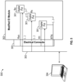
- FIGS. 3 , 4 , and 5 depict different systems 300, 400, 500, respectively, for using an identification module for a turbine engine or APU with extended data storage capacity.
- the systems 300, 400, 500 include an ID module 302 that includes a PCB 305 having a plurality of digital potentiometers 301 (or "digital pots" for short).
- the digital potentiometers 301 can be arranged in different configurations as shown in FIGS. 3-5 .
- the digital potentiometers 301 are arranged in parallel.
- the digital potentiometers 301 are arranged in series.
- the digital potentiometers 301 are arranged in a combination of series and parallel.
- the digital potentiometers 301 are programmable resistors. Different COTS digital potentiometers have different resistance ranges and numbers of taps (e.g., 128, 256, 1024), thereby providing different resolution.
- the digital potentiometers 301 are installed or mounted on the PCB 305 and embedded in an enclosure that forms the ID module 302.
- the digital potentiometers 301 can be programmed via an electrical connector 303, which is also used to connect the ID module 302 to the APU control system and EEC.
- the digital potentiometers 301 can be programmed using a computer 304 with dedicated software, including a graphical user interface for example, that enables a user to input a desired value to be coded (e.g., APU serial number) and software on the computer 304 performs the coding and digital potentiometer programming.
- a desired value to be coded e.g., APU serial number
- one or more of the digital potentiometers 301 are reprogrammable such that they are used to store dynamic information that can change through the lifecycle of the APU or turbine engine. Examples of such dynamic information includes an EGT trim, a torque trim, and/or the like, including combinations and/or multiples thereof. According to one or more embodiments described herein, one or more of the digital potentiometers 301 are fusible such that they are fixed once programmed, intended to be used to store static information. Examples of such static information include engine identification data, serial number, and/or the like, including combinations and/or multiples thereof.
- FIGS. 3-5 provide a modular approach to the ID module 302, where the digital potentiometers 301 can be reprogrammed without additional workmanship and hardware manipulation.
- a conventional ID modules are modernized by using modern digital components (e.g., the digital potentiometers 301) which provide benefits such as ease of programming, component availability and the like in a manner that remains transparent to the control system, as the digital potentiometer 301 is perceived by the EEC as a simple resistance.
- Information stored in the ID module 302 is often read by the EEC once during APU or turbine engine cycle and is re-written to EEC EEPROM. Accordingly, the ID module 302, using the digital potentiometers 301, does not require re-certification of the control system.
- ID module 302 can be flexibly adjusted to meet the interface requirements of the legacy EEC.
- Information in the ID module 302 can be coded in an analog (e.g., look-up table EGT trim vs. resistance) and binary fashion (e.g., serial number).
Landscapes
- Engineering & Computer Science (AREA)
- Combustion & Propulsion (AREA)
- Chemical & Material Sciences (AREA)
- General Engineering & Computer Science (AREA)
- Physics & Mathematics (AREA)
- General Physics & Mathematics (AREA)
- Theoretical Computer Science (AREA)
- Mechanical Engineering (AREA)
- Aviation & Aerospace Engineering (AREA)
- Data Mining & Analysis (AREA)
- Automation & Control Theory (AREA)
- Evolutionary Computation (AREA)
- Computing Systems (AREA)
- Manufacturing & Machinery (AREA)
- Quality & Reliability (AREA)
- Software Systems (AREA)
- Artificial Intelligence (AREA)
- Health & Medical Sciences (AREA)
- General Health & Medical Sciences (AREA)
- Computer Vision & Pattern Recognition (AREA)
- Life Sciences & Earth Sciences (AREA)
- Medical Informatics (AREA)
- Mathematical Physics (AREA)
- Biophysics (AREA)
- Molecular Biology (AREA)
- Bioinformatics & Cheminformatics (AREA)
- Bioinformatics & Computational Biology (AREA)
- Evolutionary Biology (AREA)
- Computational Linguistics (AREA)
- Computer Networks & Wireless Communication (AREA)
- Biomedical Technology (AREA)
- Signal Processing (AREA)
- Control Of Turbines (AREA)
- Control Of Eletrric Generators (AREA)
- Charge And Discharge Circuits For Batteries Or The Like (AREA)
Applications Claiming Priority (1)
| Application Number | Priority Date | Filing Date | Title |
|---|---|---|---|
| US18/159,834 US20240254918A1 (en) | 2023-01-26 | 2023-01-26 | Identification module for turbine engine or auxiliary power unit with extended data storage capacity |
Publications (2)
| Publication Number | Publication Date |
|---|---|
| EP4407172A2 true EP4407172A2 (de) | 2024-07-31 |
| EP4407172A3 EP4407172A3 (de) | 2024-10-09 |
Family
ID=89707716
Family Applications (1)
| Application Number | Title | Priority Date | Filing Date |
|---|---|---|---|
| EP24153520.2A Pending EP4407172A3 (de) | 2023-01-26 | 2024-01-23 | Identifikationsmodul für turbinenmotor oder hilfstriebwerk mit erweiterter datenspeicherkapazität |
Country Status (3)
| Country | Link |
|---|---|
| US (1) | US20240254918A1 (de) |
| EP (1) | EP4407172A3 (de) |
| CA (1) | CA3224048A1 (de) |
Family Cites Families (3)
| Publication number | Priority date | Publication date | Assignee | Title |
|---|---|---|---|---|
| US5146172A (en) * | 1990-08-15 | 1992-09-08 | Sundstrand Corp. | Engine identification system |
| US7505820B2 (en) * | 2006-03-30 | 2009-03-17 | Honeywell International Inc. | Backup control for solid state power controller (SSPC) |
| US8170836B1 (en) * | 2008-02-04 | 2012-05-01 | Invocon, Inc. | Low-power triggered data acquisition system and method |
-
2023
- 2023-01-26 US US18/159,834 patent/US20240254918A1/en active Pending
- 2023-12-20 CA CA3224048A patent/CA3224048A1/en active Pending
-
2024
- 2024-01-23 EP EP24153520.2A patent/EP4407172A3/de active Pending
Also Published As
| Publication number | Publication date |
|---|---|
| US20240254918A1 (en) | 2024-08-01 |
| EP4407172A3 (de) | 2024-10-09 |
| CA3224048A1 (en) | 2025-04-10 |
Similar Documents
| Publication | Publication Date | Title |
|---|---|---|
| EP3789603B1 (de) | Elektrische hilfskraftunterstützung für motorneustart im flug | |
| EP1505279B1 (de) | Kraftstoffsteuerung für Gasturbinen | |
| EP3358144B1 (de) | Schubleistungsabhängiges aktives spitzenspaltkontrollsystem | |
| US12116940B2 (en) | Corrected parameters control logic for variable geometry mechanisms | |
| EP3779147B1 (de) | Rotordynamikausgleich unter verwendung von elektrischem hilfsantrieb | |
| US12123344B2 (en) | Engine and secondary power unit integrated operation | |
| US12253030B2 (en) | In-flight engine re-start | |
| EP3249199B1 (de) | Gasturbinentriebwerkeinlasstemperatursensorkonfiguration sowie dazugehöriges verfahren | |
| EP3450700A1 (de) | Schwingungssteuerung für einen gasturbinenmotor | |
| US20190063333A1 (en) | Method for selection of optimal engine operating conditions for generating linearized models for on-board control and estimation | |
| EP3767090B2 (de) | Steuerung der betriebsfähigkeit eines kompressors für einen hybriden elektrischen antrieb | |
| EP4407172A2 (de) | Identifikationsmodul für turbinenmotor oder hilfstriebwerk mit erweiterter datenspeicherkapazität | |
| US20210324756A1 (en) | Model-based rotor speed keep out zone control | |
| US6605948B2 (en) | Test system for a gas turbine engine control programming plug | |
| EP3640436A1 (de) | Steuerlogik eines verdichtergehäusespiels | |
| US11649763B1 (en) | Rating control architecture and method for hybrid electric engine | |
| US11306654B2 (en) | Gas turbine engine system wear reduction | |
| EP3633167A1 (de) | Korrigierte kraftstoffdurchflussbasierte steuerung für mechanismen mit variabler geometrie | |
| EP3318859B1 (de) | Sicherheit von gekühlter kühlluft durch eine temperaturüberwachungsleitungauswechseleinheit | |
| EP4102045B1 (de) | Faseroptische austrittsflächenerfassung für gasturbinentriebwerksdüsen | |
| EP4390089A1 (de) | Elektrisch verstärktes turbinenkühlluftsystem | |
| Bellin et al. | Status Report: DARPA/NASA Convertible Turbofan/Turboshaft Engine Program |
Legal Events
| Date | Code | Title | Description |
|---|---|---|---|
| PUAI | Public reference made under article 153(3) epc to a published international application that has entered the european phase |
Free format text: ORIGINAL CODE: 0009012 |
|
| STAA | Information on the status of an ep patent application or granted ep patent |
Free format text: STATUS: THE APPLICATION HAS BEEN PUBLISHED |
|
| AK | Designated contracting states |
Kind code of ref document: A2 Designated state(s): AL AT BE BG CH CY CZ DE DK EE ES FI FR GB GR HR HU IE IS IT LI LT LU LV MC ME MK MT NL NO PL PT RO RS SE SI SK SM TR |
|
| PUAL | Search report despatched |
Free format text: ORIGINAL CODE: 0009013 |
|
| AK | Designated contracting states |
Kind code of ref document: A3 Designated state(s): AL AT BE BG CH CY CZ DE DK EE ES FI FR GB GR HR HU IE IS IT LI LT LU LV MC ME MK MT NL NO PL PT RO RS SE SI SK SM TR |
|
| RIC1 | Information provided on ipc code assigned before grant |
Ipc: F02C 9/28 20060101ALI20240902BHEP Ipc: F02C 9/00 20060101AFI20240902BHEP |
|
| STAA | Information on the status of an ep patent application or granted ep patent |
Free format text: STATUS: REQUEST FOR EXAMINATION WAS MADE |
|
| 17P | Request for examination filed |
Effective date: 20250409 |