EP4407105A1 - Improved tank for a vehicle - Google Patents
Improved tank for a vehicle Download PDFInfo
- Publication number
- EP4407105A1 EP4407105A1 EP24154275.2A EP24154275A EP4407105A1 EP 4407105 A1 EP4407105 A1 EP 4407105A1 EP 24154275 A EP24154275 A EP 24154275A EP 4407105 A1 EP4407105 A1 EP 4407105A1
- Authority
- EP
- European Patent Office
- Prior art keywords
- tank
- inlet
- generation means
- outlet
- energy generation
- Prior art date
- Legal status (The legal status is an assumption and is not a legal conclusion. Google has not performed a legal analysis and makes no representation as to the accuracy of the status listed.)
- Granted
Links
Images

Classifications
-
- E—FIXED CONSTRUCTIONS
- E02—HYDRAULIC ENGINEERING; FOUNDATIONS; SOIL SHIFTING
- E02F—DREDGING; SOIL-SHIFTING
- E02F9/00—Component parts of dredgers or soil-shifting machines, not restricted to one of the kinds covered by groups E02F3/00 - E02F7/00
- E02F9/20—Drives; Control devices
- E02F9/22—Hydraulic or pneumatic drives
- E02F9/2217—Hydraulic or pneumatic drives with energy recovery arrangements, e.g. using accumulators, flywheels
-
- F—MECHANICAL ENGINEERING; LIGHTING; HEATING; WEAPONS; BLASTING
- F15—FLUID-PRESSURE ACTUATORS; HYDRAULICS OR PNEUMATICS IN GENERAL
- F15B—SYSTEMS ACTING BY MEANS OF FLUIDS IN GENERAL; FLUID-PRESSURE ACTUATORS, e.g. SERVOMOTORS; DETAILS OF FLUID-PRESSURE SYSTEMS, NOT OTHERWISE PROVIDED FOR
- F15B1/00—Installations or systems with accumulators; Supply reservoir or sump assemblies
- F15B1/26—Supply reservoir or sump assemblies
-
- F—MECHANICAL ENGINEERING; LIGHTING; HEATING; WEAPONS; BLASTING
- F15—FLUID-PRESSURE ACTUATORS; HYDRAULICS OR PNEUMATICS IN GENERAL
- F15B—SYSTEMS ACTING BY MEANS OF FLUIDS IN GENERAL; FLUID-PRESSURE ACTUATORS, e.g. SERVOMOTORS; DETAILS OF FLUID-PRESSURE SYSTEMS, NOT OTHERWISE PROVIDED FOR
- F15B21/00—Common features of fluid actuator systems; Fluid-pressure actuator systems or details thereof, not covered by any other group of this subclass
- F15B21/14—Energy-recuperation means
Definitions
- the present invention concerns a tank for a work vehicle.
- the present invention finds its preferred, although not exclusive, application in work vehicles such as earth moving machines. Reference will be made to this application by way of example below.
- Work vehicles such as earth moving machines use power provided by power sources such as internal combustion engine or electric machines powered by batteries to operate a variety of utilities.
- FIG. 1 An example of prior art tank 1' that is used in hydraulic system of a work vehicle is shown exemplarily in Figure 1 .
- Such tank 1' comprises a plurality of walls 2' that delimit a space 3' configured to house the hydraulic fluid coming from outlets of the hydraulic systems via an inlet 4'. The collected hydraulic fluid is then filtered and provided to inlet of the hydraulic system via an outlet 5'.
- An aim of the present invention is to satisfy the above mentioned needs in a cost-effective and optimized manner.
- Figure 1 discloses a tank 1 for a hydraulic system (not shown) of a work vehicle (not shown) such as an earth moving machine or an agricultural vehicle.
- the tank 1 comprises a plurality of walls 2 connected together to define a space 3 for housing a hydraulic fluid such as an operative fluid of the hydraulic system, e.g. oil or water.
- a hydraulic fluid such as an operative fluid of the hydraulic system, e.g. oil or water.
- the hydraulic system is an hydraulic oil system of the work vehicle.
- the tank 1 has a substantially parallelepiped shape, i.e. comprising a top plate 2a, a bottom plate 2b and a plurality of lateral walls 2c connecting together the top and bottom plates 2a, 2b.
- the walls 2 are connected together to define a space 3 configured to house the aforementioned hydraulic fluid.
- the top and bottom plates 2a, 2b are spaced along a first axis A, vertical, and delimit the space 3 along such direction and the lateral walls 2c connects the top and bottom plates 2a, 2b along their perimeter and delimit the space 3 along a second axis B, transversal, direction.
- the tank 1 further defines an inlet 4 and an outlet 5 configured to be respectively connected to an outlet and an inlet of at least a hydraulic system of the work vehicle.
- the inlet 4 is realized in top plate 2a while outlet 5 is realized in the bottom plate 2b.
- the inlet 4 and the outlet 5 are defined by conduits 4', 5' carried by the respective plate 2a, 2b and extending from this latter within space 3.
- Such conduit 4', 5' is fluidly connected to the aforementioned outlet/inlet of the hydraulic systems, e.g. by dedicated conduits or hoses.
- the tank 1 is provided with filtering means 6 configured to filter the hydraulic fluid before sending the latter towards the inlet of hydraulic systems. Similar filtering means may be provided also downstream to the inlet 4, even if not explicitly shown herewith.
- Such filtering means may be also be integrated into pumping means, here further not shown, according to the specific need of the work vehicle and/or of the hydraulic systems.
- the tank 1 further comprises a separation wall 7 housed within space 3 and configured to divide this latter in a first portion 3' and a second portion 3".
- the separation walls 7 is carried by a pair of lateral walls 2c and the first portion 3' houses the inlet 4 and the second portion 3'' houses the outlet 5.
- the separation wall 7 extends along the first axis direction A and is preferably spaced from the top plate 2a and the bottom plate 2b thereby defining an upper gap 8' and a lower gap 8".
- the hydraulic fluid coming from inlet 4 flows passing from lower gap 8" towards the outlet 5 and, in case of overflow, may pass from upper gap 8'.
- the tank 1 is provided with energy generation means 10 configured to generate electric energy from hydraulic fluid movement from the inlet 4 towards the outlet 5.
- energy generation means 10 are housed in space 3 so that the movement of fluid between inlet and outlet 4, 5 allows the generation of electrical energy.
- the energy generation means 10 are housed in space 3, more in detail in the first portion 3' and advantageously in proximity of lower gap 8".
- the energy generation means 10 comprises a rotating portion 11 and a supporting shaft 12, the rotating portion 11 is carried engaged in rotation with the supporting shaft 12 and is configured to be propelled by the movement of hydraulic fluid therethrough.
- the supporting shaft 12 carried by housing 2 in a rotatably free manner and is connected to an energy generation device G, e.g. mechanically, such as a generator configured to produce electrical energy via supporting shaft 12 rotation.
- G an energy generation device G, e.g. mechanically, such as a generator configured to produce electrical energy via supporting shaft 12 rotation.
- the supporting shaft 12 is carried by two lateral walls 2c so that the supporting shaft 12 can rotate about an axis perpendicular to axis A and B.
- the rotating portion 11 is shaped in order to receive a pushing force by the hydraulic fluid in movement in order to produce a rotation of the supporting shaft 12.
- the rotating portion 11 may comprise at least a vane configured to be pushed by the hydraulic fluid.
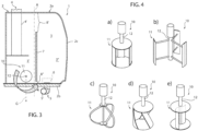
- Figures 4a to 4e discloses different embodiments of the rotating portion 11 comprising each different number and typology of shovels.
- the shovel may be one or more among a squirrel cage darricus shovel ( figure 4a ), a H-darricus shovel ( figure 4b ), a darricus shovel ( figure 4c ), a gorlov shovel ( figure 4d ) or a savonius shovel ( figure 4e ).
- the hydraulic fluid is stored in the tank 1 passing from inlet 4 towards outlet 5 through space 3 and in particular through gap 3'' .
- its velocity is therefore at its maximum value in gap 3'; therefore, fluid passes from the energy generator means 10 that are housed in the proximity of the gap 3'.
- the rotating portion 11 is therefore pushed by the passage of the fluid that makes rotate the supporting shaft 12 whose rotation is used by generation means G to produce electrical energy.
- electrical energy may be used for operating other electrical elements of the vehicle.
- the proposed tank arrangement allows to recovery part of the kinetic energy that is still available in the flow and that would be otherwise wasted.
- the energy generation means 10 may be used for any typology of hydraulic fluid and in any shape and typology of tank, thereby being adapt to be installed also in existing tanks with minor modifications.
- the shape of the tank may vary such as the shape and number of inlet and outlet.
- the tank may comprise more energy generation means of different size and shapes provided they comprise the operational claimed features.
- the energy generation means 10 could be placed within one between inlet 4 and outlet 5 conduits, in particular in inlet 4.
Landscapes
- Engineering & Computer Science (AREA)
- General Engineering & Computer Science (AREA)
- Physics & Mathematics (AREA)
- Fluid Mechanics (AREA)
- Mechanical Engineering (AREA)
- Chemical & Material Sciences (AREA)
- Analytical Chemistry (AREA)
- Mining & Mineral Resources (AREA)
- Civil Engineering (AREA)
- Structural Engineering (AREA)
- Other Liquid Machine Or Engine Such As Wave Power Use (AREA)
Abstract
Description
- The present invention concerns a tank for a work vehicle.
- The present invention finds its preferred, although not exclusive, application in work vehicles such as earth moving machines. Reference will be made to this application by way of example below.
- Work vehicles such as earth moving machines use power provided by power sources such as internal combustion engine or electric machines powered by batteries to operate a variety of utilities.
- Making reference to hydraulic systems of the work vehicle, it is widely known that they are particularly energy consuming. In particular, the energy consumption of such hydraulic system is due to the energy need to carry the pumping means that feed hydraulic fluid at high pressure to operate the work vehicle system and to the energy losses
- An example of prior art tank 1' that is used in hydraulic system of a work vehicle is shown exemplarily in
Figure 1 . Such tank 1' comprises a plurality of walls 2' that delimit a space 3' configured to house the hydraulic fluid coming from outlets of the hydraulic systems via an inlet 4'. The collected hydraulic fluid is then filtered and provided to inlet of the hydraulic system via an outlet 5'. - Due to the increasing need to provide environmental friendly vehicles, it is felt to improve efficiency of the vehicles by reducing the overall power consumption of the vehicle.
- In view of the above, the need is felt to optimize the energetic balance of the work vehicles provided with hydraulic systems in order to reduce the overall power consumption of these latter.
- An aim of the present invention is to satisfy the above mentioned needs in a cost-effective and optimized manner.
- The aforementioned aim is reached by tank, a hydraulic system and a vehicle as claimed in the appended set of claims.
- For a better understanding of the present invention, a preferred embodiment is described in the following, by way of a non-limiting example, with reference to the attached drawings wherein:
-
Figure 1 is perspective view of a prior art tank of a hydraulic system of a work vehicle; -
Figure 2 is perspective view of a tank according to the invention of a hydraulic system of a work vehicle; -
Figure 3 is a lateral view of the tank offigure 2 ; and -
Figures 4a-4e are schematic representations of a portion of the tank according to the invention. -
Figure 1 discloses a tank 1 for a hydraulic system (not shown) of a work vehicle (not shown) such as an earth moving machine or an agricultural vehicle. - The tank 1 comprises a plurality of walls 2 connected together to define a
space 3 for housing a hydraulic fluid such as an operative fluid of the hydraulic system, e.g. oil or water. Preferably, the hydraulic system is an hydraulic oil system of the work vehicle. - In the disclosed example, the tank 1 has a substantially parallelepiped shape, i.e. comprising a
top plate 2a, abottom plate 2b and a plurality oflateral walls 2c connecting together the top andbottom plates - The walls 2 are connected together to define a
space 3 configured to house the aforementioned hydraulic fluid. In particular, the top andbottom plates space 3 along such direction and thelateral walls 2c connects the top andbottom plates space 3 along a second axis B, transversal, direction. - The tank 1 further defines an
inlet 4 and anoutlet 5 configured to be respectively connected to an outlet and an inlet of at least a hydraulic system of the work vehicle. - In particular, the
inlet 4 is realized intop plate 2a whileoutlet 5 is realized in thebottom plate 2b. Preferably, as shown, theinlet 4 and theoutlet 5 are defined by conduits 4', 5' carried by therespective plate space 3. Such conduit 4', 5' is fluidly connected to the aforementioned outlet/inlet of the hydraulic systems, e.g. by dedicated conduits or hoses. - Preferably, at least fluidically upstream to
outlet 5, the tank 1 is provided with filtering means 6 configured to filter the hydraulic fluid before sending the latter towards the inlet of hydraulic systems. Similar filtering means may be provided also downstream to theinlet 4, even if not explicitly shown herewith. - Such filtering means may be also be integrated into pumping means, here further not shown, according to the specific need of the work vehicle and/or of the hydraulic systems.
- Preferably the tank 1 further comprises a
separation wall 7 housed withinspace 3 and configured to divide this latter in a first portion 3' and asecond portion 3". In particular, theseparation walls 7 is carried by a pair oflateral walls 2c and the first portion 3' houses theinlet 4 and the second portion 3'' houses theoutlet 5. - In detail, the
separation wall 7 extends along the first axis direction A and is preferably spaced from thetop plate 2a and thebottom plate 2b thereby defining an upper gap 8' and alower gap 8". The hydraulic fluid coming frominlet 4 flows passing fromlower gap 8" towards theoutlet 5 and, in case of overflow, may pass from upper gap 8'. - According to the invention, the tank 1 is provided with energy generation means 10 configured to generate electric energy from hydraulic fluid movement from the
inlet 4 towards theoutlet 5. - Accordingly, energy generation means 10 are housed in
space 3 so that the movement of fluid between inlet andoutlet space 3, more in detail in the first portion 3' and advantageously in proximity oflower gap 8". - In detail, the energy generation means 10 comprises a rotating
portion 11 and a supportingshaft 12, the rotatingportion 11 is carried engaged in rotation with the supportingshaft 12 and is configured to be propelled by the movement of hydraulic fluid therethrough. - The supporting
shaft 12 carried by housing 2 in a rotatably free manner and is connected to an energy generation device G, e.g. mechanically, such as a generator configured to produce electrical energy via supportingshaft 12 rotation. - Preferably, in the disclosed embodiment, the supporting
shaft 12 is carried by twolateral walls 2c so that the supportingshaft 12 can rotate about an axis perpendicular to axis A and B. - The rotating
portion 11 is shaped in order to receive a pushing force by the hydraulic fluid in movement in order to produce a rotation of the supportingshaft 12. In particular, the rotatingportion 11 may comprise at least a vane configured to be pushed by the hydraulic fluid. -
Figures 4a to 4e discloses different embodiments of therotating portion 11 comprising each different number and typology of shovels. In particular, but not in a limitative way, the shovel may be one or more among a squirrel cage darricus shovel (figure 4a ), a H-darricus shovel (figure 4b ), a darricus shovel (figure 4c ), a gorlov shovel (figure 4d ) or a savonius shovel (figure 4e ). - The operation of the embodiment of the invention as described above is the following.
- During the operation of the vehicle, the hydraulic fluid is stored in the tank 1 passing from
inlet 4 towardsoutlet 5 throughspace 3 and in particular through gap 3'' . During such passage its velocity is therefore at its maximum value in gap 3'; therefore, fluid passes from the energy generator means 10 that are housed in the proximity of the gap 3'. The rotatingportion 11 is therefore pushed by the passage of the fluid that makes rotate the supportingshaft 12 whose rotation is used by generation means G to produce electrical energy. Such electrical energy may be used for operating other electrical elements of the vehicle. - In view of the foregoing, the advantages of tank, hydraulic system and vehicle according to the invention are apparent.
- The proposed tank arrangement allows to recovery part of the kinetic energy that is still available in the flow and that would be otherwise wasted.
- In detail, the energy generation means 10 may be used for any typology of hydraulic fluid and in any shape and typology of tank, thereby being adapt to be installed also in existing tanks with minor modifications.
- In detail, the use in oil hydraulic systems in work vehicle, due to density and pressures of oil, allows to recovery a considerable energy quantity without increasing the pressure drop in the related hydraulic circuits.
- The peculiar positioning in the lower gap where the speed is maximized allows to use the maximum of kinetic energy of the fluid to be provided to the generator.
- It is clear that modifications can be made to the described tank, hydraulic system and vehicle which do not extend beyond the scope of protection defined by the claims.
- For example, the shape of the tank may vary such as the shape and number of inlet and outlet.
- Similarly, the tank may comprise more energy generation means of different size and shapes provided they comprise the operational claimed features.
- Moreover, the energy generation means 10 could be placed within one between
inlet 4 andoutlet 5 conduits, in particular ininlet 4.
Claims (10)
- Tank (1) for a hydraulic system of a vehicle, said tank (1) comprising a housing (2) defining a space (3) for housing a hydraulic fluid, said tank (1) comprising an inlet (4) and an outlet (5) configured to allow the filling and spilling of said hydraulic fluid to/from said space (3) with respect to said hydraulic system, said tank (1) comprising energy generation means (10) configured to generate electrical energy from the movement of said hydraulic fluid from said inlet (4) towards said outlet (5).
- Tank according to claim 1, wherein said energy generation means (10) comprises a rotating portion (11) and a supporting shaft (12) carried in a rotatably free manner by said housing (2), said rotating portion (12) being configured to be pushed by the movement of said fluid, said supporting shaft (12) being connected to a generator (G) configured to generate electrical energy from the rotation of said supporting shaft (12).
- Tank according to claim 2, wherein said rotating portion (11) is carried in a rigid manner by said supporting shaft (12).
- Tank according to claim 2 or 3, wherein said rotating portion (11) comprises one or more among a squirrel cage darricus shovel, a H-darricus shovel, a darricus shovel, a gorlov shovel or a savonius shovel.
- Tank according to any of the preceding claims, wherein said housing (2) comprises a top and a bottom walls (2a, 2b) and a plurality of lateral walls (2c), said energy generation means (10) are carried by said lateral walls (2c).
- Tank according to claim 5, wherein said tank (1) comprises a separation wall (7) housed within said space (3) and dividing this latter into a first portion (3') connected to said inlet (4) and a second portion (3") connected to said outlet (5), said separation wall (7) defining an upper gap (8') and a lower gap (8") with respectively said top and bottom walls (2a, 2b), said energy generation means (10) being housed in said first portion (3').
- Tank according to claim 6, wherein said energy generation means (10) is housed in proximity of said lower gap (8").
- Tank according to any of claims 1 to 5, wherein said energy generation means (10) are integrated in one between inlet and outlet (4, 5) conduits.
- Hydraulic system for a vehicle comprising a tank as claimed in any of the preceding claims.
- Work vehicle comprising at least one hydraulic system as claimed in claim 9.
Applications Claiming Priority (1)
| Application Number | Priority Date | Filing Date | Title |
|---|---|---|---|
| IT102023000001332A IT202300001332A1 (en) | 2023-01-27 | 2023-01-27 | IMPROVED VEHICLE TANK |
Publications (2)
| Publication Number | Publication Date |
|---|---|
| EP4407105A1 true EP4407105A1 (en) | 2024-07-31 |
| EP4407105B1 EP4407105B1 (en) | 2026-06-10 |
Family
ID=85685242
Family Applications (1)
| Application Number | Title | Priority Date | Filing Date |
|---|---|---|---|
| EP24154275.2A Active EP4407105B1 (en) | 2023-01-27 | 2024-01-26 | Improved tank for a vehicle |
Country Status (2)
| Country | Link |
|---|---|
| EP (1) | EP4407105B1 (en) |
| IT (1) | IT202300001332A1 (en) |
Citations (3)
| Publication number | Priority date | Publication date | Assignee | Title |
|---|---|---|---|---|
| KR20040083168A (en) * | 2003-03-21 | 2004-10-01 | 학교법인 울산공업학원 | recovery and regeneration apparatus of hydraulic energy |
| US20180347152A1 (en) * | 2017-06-05 | 2018-12-06 | Caterpillar Inc. | Kinetic energy recovery system for a machine |
| CN114855923A (en) * | 2022-05-30 | 2022-08-05 | 柳州柳工挖掘机有限公司 | Rotary kinetic energy recovery device and excavator |
-
2023
- 2023-01-27 IT IT102023000001332A patent/IT202300001332A1/en unknown
-
2024
- 2024-01-26 EP EP24154275.2A patent/EP4407105B1/en active Active
Patent Citations (3)
| Publication number | Priority date | Publication date | Assignee | Title |
|---|---|---|---|---|
| KR20040083168A (en) * | 2003-03-21 | 2004-10-01 | 학교법인 울산공업학원 | recovery and regeneration apparatus of hydraulic energy |
| US20180347152A1 (en) * | 2017-06-05 | 2018-12-06 | Caterpillar Inc. | Kinetic energy recovery system for a machine |
| CN114855923A (en) * | 2022-05-30 | 2022-08-05 | 柳州柳工挖掘机有限公司 | Rotary kinetic energy recovery device and excavator |
Also Published As
| Publication number | Publication date |
|---|---|
| EP4407105B1 (en) | 2026-06-10 |
| IT202300001332A1 (en) | 2024-07-27 |
Similar Documents
| Publication | Publication Date | Title |
|---|---|---|
| US5377485A (en) | Electric power conversion system | |
| RU2013118634A (en) | DEVICE FOR TRANSFORMING WAVE ENERGY TO ELECTRIC ENERGY IN A HYDROSTATIC LAYER | |
| WO2009031016A2 (en) | An energy generating system using a plurality of waterwheels | |
| JP5139600B2 (en) | Unit for hydroelectric power plant and modular hydroelectric power plant comprising said unit | |
| CN102812235A (en) | Rotational force generating device and a centripetally acting type of water turbine using the same | |
| CS198171B2 (en) | Hydraulic engine | |
| US9657708B2 (en) | Pumped-storage system | |
| CN107381683A (en) | A kind of filter for being used for muddy sewage in hydroelectric generation | |
| US7658065B2 (en) | Hydraulic system having in-sump energy recovery device | |
| KR102086304B1 (en) | Hybrid Water Generator Device and Water Quality Improvement System | |
| CN102032089A (en) | Series-connection multi-time hydraulic generating system | |
| CN212225433U (en) | Tower box type wind, water and pump multi-stage combined generator set | |
| EP2873851A1 (en) | Aerating system for hydraulic turbine | |
| CA2820836A1 (en) | Pump-turbine system | |
| CN215949813U (en) | Large-flow small-volume double-stack combined pump | |
| IT202300001332A1 (en) | IMPROVED VEHICLE TANK | |
| CN201666319U (en) | Variable speed hydraulic coupling of grab dredger | |
| JP4287172B2 (en) | Hydroelectric generator | |
| CN105465035B (en) | Air conditioner and centrifugal compressor thereof | |
| CN201155408Y (en) | A device for controlling the runner blades of a water turbine unit | |
| EP4461579B1 (en) | Energy recovery system for a vehicular system of a work vehicle | |
| CN219587878U (en) | Hydraulic oil tank | |
| CN203412812U (en) | Multifunctional porous flow-conducting pump structure | |
| CN208901048U (en) | A kind of shared lube plant | |
| KR101771329B1 (en) | Marine power generation system |
Legal Events
| Date | Code | Title | Description |
|---|---|---|---|
| PUAI | Public reference made under article 153(3) epc to a published international application that has entered the european phase |
Free format text: ORIGINAL CODE: 0009012 |
|
| STAA | Information on the status of an ep patent application or granted ep patent |
Free format text: STATUS: THE APPLICATION HAS BEEN PUBLISHED |
|
| AK | Designated contracting states |
Kind code of ref document: A1 Designated state(s): AL AT BE BG CH CY CZ DE DK EE ES FI FR GB GR HR HU IE IS IT LI LT LU LV MC ME MK MT NL NO PL PT RO RS SE SI SK SM TR |
|
| STAA | Information on the status of an ep patent application or granted ep patent |
Free format text: STATUS: REQUEST FOR EXAMINATION WAS MADE |
|
| 17P | Request for examination filed |
Effective date: 20250131 |
|
| GRAP | Despatch of communication of intention to grant a patent |
Free format text: ORIGINAL CODE: EPIDOSNIGR1 |
|
| STAA | Information on the status of an ep patent application or granted ep patent |
Free format text: STATUS: GRANT OF PATENT IS INTENDED |
|
| INTG | Intention to grant announced |
Effective date: 20260126 |
|
| GRAS | Grant fee paid |
Free format text: ORIGINAL CODE: EPIDOSNIGR3 |
|
| GRAA | (expected) grant |
Free format text: ORIGINAL CODE: 0009210 |
|
| STAA | Information on the status of an ep patent application or granted ep patent |
Free format text: STATUS: THE PATENT HAS BEEN GRANTED |
|
| AK | Designated contracting states |
Kind code of ref document: B1 Designated state(s): AL AT BE BG CH CY CZ DE DK EE ES FI FR GB GR HR HU IE IS IT LI LT LU LV MC ME MK MT NL NO PL PT RO RS SE SI SK SM TR |
|
| REG | Reference to a national code |
Ref country code: CH Ref legal event code: F10 Free format text: ST27 STATUS EVENT CODE: U-0-0-F10-F00 (AS PROVIDED BY THE NATIONAL OFFICE) Effective date: 20260610 Ref country code: GB Ref legal event code: FG4D |
|
| REG | Reference to a national code |
Ref country code: DE Ref legal event code: R096 Ref document number: 602024005312 Country of ref document: DE |
|
| REG | Reference to a national code |
Ref country code: IE Ref legal event code: FG4D |