EP4406880A2 - System for distributing heavy bins in a storage grid - Google Patents
System for distributing heavy bins in a storage grid Download PDFInfo
- Publication number
- EP4406880A2 EP4406880A2 EP24169087.4A EP24169087A EP4406880A2 EP 4406880 A2 EP4406880 A2 EP 4406880A2 EP 24169087 A EP24169087 A EP 24169087A EP 4406880 A2 EP4406880 A2 EP 4406880A2
- Authority
- EP
- European Patent Office
- Prior art keywords
- storage
- bin
- weight
- storage bin
- bins
- Prior art date
- Legal status (The legal status is an assumption and is not a legal conclusion. Google has not performed a legal analysis and makes no representation as to the accuracy of the status listed.)
- Pending
Links
Images



Classifications
-
- B—PERFORMING OPERATIONS; TRANSPORTING
- B65—CONVEYING; PACKING; STORING; HANDLING THIN OR FILAMENTARY MATERIAL
- B65G—TRANSPORT OR STORAGE DEVICES, e.g. CONVEYORS FOR LOADING OR TIPPING, SHOP CONVEYOR SYSTEMS OR PNEUMATIC TUBE CONVEYORS
- B65G1/00—Storing articles, individually or in orderly arrangement, in warehouses or magazines
- B65G1/02—Storage devices
- B65G1/04—Storage devices mechanical
-
- B—PERFORMING OPERATIONS; TRANSPORTING
- B65—CONVEYING; PACKING; STORING; HANDLING THIN OR FILAMENTARY MATERIAL
- B65G—TRANSPORT OR STORAGE DEVICES, e.g. CONVEYORS FOR LOADING OR TIPPING, SHOP CONVEYOR SYSTEMS OR PNEUMATIC TUBE CONVEYORS
- B65G1/00—Storing articles, individually or in orderly arrangement, in warehouses or magazines
- B65G1/02—Storage devices
- B65G1/04—Storage devices mechanical
- B65G1/0464—Storage devices mechanical with access from above
-
- B—PERFORMING OPERATIONS; TRANSPORTING
- B65—CONVEYING; PACKING; STORING; HANDLING THIN OR FILAMENTARY MATERIAL
- B65G—TRANSPORT OR STORAGE DEVICES, e.g. CONVEYORS FOR LOADING OR TIPPING, SHOP CONVEYOR SYSTEMS OR PNEUMATIC TUBE CONVEYORS
- B65G1/00—Storing articles, individually or in orderly arrangement, in warehouses or magazines
- B65G1/02—Storage devices
- B65G1/04—Storage devices mechanical
- B65G1/137—Storage devices mechanical with arrangements or automatic control means for selecting which articles are to be removed
- B65G1/1371—Storage devices mechanical with arrangements or automatic control means for selecting which articles are to be removed with data records
-
- G—PHYSICS
- G05—CONTROLLING; REGULATING
- G05B—CONTROL OR REGULATING SYSTEMS IN GENERAL; FUNCTIONAL ELEMENTS OF SUCH SYSTEMS; MONITORING OR TESTING ARRANGEMENTS FOR SUCH SYSTEMS OR ELEMENTS
- G05B11/00—Automatic controllers
- G05B11/01—Automatic controllers electric
-
- B—PERFORMING OPERATIONS; TRANSPORTING
- B65—CONVEYING; PACKING; STORING; HANDLING THIN OR FILAMENTARY MATERIAL
- B65G—TRANSPORT OR STORAGE DEVICES, e.g. CONVEYORS FOR LOADING OR TIPPING, SHOP CONVEYOR SYSTEMS OR PNEUMATIC TUBE CONVEYORS
- B65G2203/00—Indexing code relating to control or detection of the articles or the load carriers during conveying
- B65G2203/02—Control or detection
- B65G2203/0208—Control or detection relating to the transported articles
- B65G2203/0258—Weight of the article
Definitions
- the present invention relates to a storage system for storing storage bins.
- the present invention also relates to a method for storing storage bins in a storage system.
- the storage system 3 includes a bin storing grid 15 defining storage columns 8 into which storage bins 2 are stacked above each other by means of robot vehicles 1.
- the upper part of the grid 15 comprises a horizontal base 14 with supporting rails 13 onto which the robot vehicles 1 are moving.
- Each robot vehicle 1 comprises a bin lift for lifting storage bins 2 up from the storage columns 8 and for elevating storage bins 2 down into the storage columns 8.
- the storage system 3 comprises a dedicated bin lift device 50, the latter being arranged to receive a storage bin 2 from the robot 1 at the top level of the storage system 3 and to convey the storage bin 2 down in a vertical direction to a delivery station, or port 60.
- a delivery station or port 60.
- items are inserted into or picked from, the storage bin 2, and thereafter, the storage bin 2 is returned to the grid via the bin lift device 50 and robot vehicle 1 again.
- a storage bin 2 is shown in detail.
- the storage bins 2 comprises reinforcement bars 2a provided in the bottom surface, the side surfaces and the upper edge defining the opening into the storage bin.
- These reinforcement bars 2a have the purpose of optimizing the strength of the storage bin while keeping the weight of the storage bin 2 itself low.
- the purpose of the reinforcement bars 2a is to be able to manufacture the storage bins from a relatively cheap material.
- the present design of the storage bins is determined by the maximum expected load Wmax (i.e. weight) of the storage bins stacked above lowermost storage bin. Hence, the worst condition for the storage bin 2 is to be the lowermost storage bin in the columns.
- Wmax i.e. weight
- the present storage system 3 causes the present storage system 3 to have a limitation in how many storage bins that can be stacked above each other and the weight of each storage bin.
- the present limits of the storage system in fig. 1 is that the maximum weight of each storage bin (i.e. weight of storage bin 2 and its product items 80) are 30 kg. and that a maximum of 14 storage bins 2 can be stacked above each other per column 8.
- These limitations have also influenced the maximum height of the grid 15, where the height of the grid 15 typically corresponds to the height of 14 storage bins. Until recently, these limitations have been sufficient for most storage systems.
- the weight of the storage bins 2 can be measured when there is doubt with respect to the 30 kg load limit.
- the weight of one type of storage bins used in present storage systems is ca 4 - 5 kg. Hence, they may carry up to a weight of 25 - 26 kg. of product items.
- the object of the present invention is to provide a storage system and a method for storing storage bins which can handle storage bins with a weight higher than the previously determined maximum weight.
- the object is to be able to store storage bins with a total weight of more than 30 kg.
- a more specific object is to provide a method and system where the weight of each storage bin including its product items (i.e. weight of the storage bin itself and the product items stored within the storage bin) can be increased without reducing the stack of storage bins in each column.
- Another more specific object of the invention is to increase the height of the grid.
- Another object of the invention is to achieve the above objects of the invention without increasing the cost per storage bin considerably. Another object is that the method and system can be implemented in an already existing storage system without too many modifications.
- the present invention relates to a method for storing product items in storage bins in a storage system comprising a bin storing grid in which storage bins are stored above each other in columns, where the method comprises the following steps:
- the step of determining the weight for each storage bin comprises the step of weighing the storage bin by means of a weight sensor.
- the step of determining the weight can be performed by estimating the weight based on a predetermined weight of each product item and the number of product items inserted into or retrieved from the storage bin.
- the predetermined weight could be the weight given by the manufacturer.
- each or all product items could be weighted by means of the weight before they are inserted into or after they have been retrieved from the storage bin.
- the port is often referred to as a supply and/or retrieval port where the product items are supplied to or inserted into the storage bins or retrieved from or picked from the storage bin.
- a supply and/or retrieval port where the product items are supplied to or inserted into the storage bins or retrieved from or picked from the storage bin.
- the same port is used for supply and retrieval, while in other storage systems, some ports are used for supply, while other ports are used for retrieval.
- the weight sensor is located at the port.
- the weight sensor is provided as part of the bin lift device of the vehicle.
- the weight can be calculated based on the current drawn from a motor of the bin lift device during lifting of the respective storage bins.
- the weight for each storage bin can be determined by means of the number of product items within the storage bin, the weight of each product item and the weight of the storage bin itself. As mentioned above, the weight of the storage bin used in present storage systems is 4 - 5 kg.
- the step of determining the storage position further comprises the steps of:
- the step of inserting product items to the respective storage bins comprises the steps of:
- the method further comprises the steps of:
- the method further comprises the steps of:
- the present invention also relates to a storage system for storing product items in storage bins, where the storage system comprises:
- the weight estimation device is a weight sensor.
- the weight sensor is located in the port. According to this embodiment, only one or a few sensors are needed in each port.
- the storage control system is configured to:
- storage control system is configured to store the total weight for all columns in the grid based on the weight and position of the storage bins, and to update the total weight of each column each time a storage bin is removed from or added to the respective columns.
- the maximum weight of one storage bin itself is no longer a limitation for the storage system.
- the present maximum weight of each storage bin is 30 kg.
- some storage bins may weigh more than 30 kg, i.e. they are overloaded or have a relatively higher weight, for example 35 or 40 kg. This is acceptable, as long as other storage bins in the same column have a weight below 30 kg, i.e. they are underloaded or have a relatively lower weight, for example 25 or 20 kg. Consequently, the maximum load for the storage bin at the lowermost level is not exceeded. It should be noted that this will require the bin lift device of each vehicle, and the vehicle itself, to be able to move a storage bin with a weight of more than 30 kg horizontally and vertically. Present vehicles are capable of this without further modifications.
- the present invention can be implemented in many presently existing storage systems, without the need for replacing all storage bins.
- the storage bins are designed for the maximum load of storage bins stacked above the storage bin when the storage bin is on the lowermost level, the storage bin will also be able to carry product items which causes its weight to be 35 - 40 kg.
- the present invention may also allow the height of the bin storing grid to be increased in storage systems where it is expected that a low percentage of storage bins have a weight of more than 30 kg. It is also possible to provide a storage system with taller columns dedicated to lighter bins and shorter columns for heavier bins. Available volume beneath the shorter columns may then be available for other type of equipment, temporary storage etc.
- the storage bin having a weight of 4 - 5 kg and the load limit of 30 kg are of course used as examples only.
- the present invention described and discussed herein can be applied to other storage systems as well.
- the storage system 3 comprises a bin storing grid 15 formed by vertical and horizontal posts connected to each other. On top of the bin storing grid 15, a base 14 for vehicles 1 is formed, where the base 14 have rails 13 for the vehicle wheels. In the bin storing grid 15, storage bins 2 are stored by stacking them above each other in columns 8.
- a coordinate system is indicated in fig. 3 , with horizontal axis x and y and a vertical axis z. Hence, each storage position P can be referred to as a position defined by its x, y, z coordinate.
- the level of the lowermost storage bin 2 in each column 8 is referred to as level z1. In the present example, the level z1 corresponds to the floor of the building in which the grid 15 is located.
- a port 60 is located on the floor, adjacent to the bin storing grid 15, a port 60 is located. At this port 60, one or more product items may be retrieved from the storage bin 2, for example based on a picking order. At this port 60, product items 80 may also be supplied to the storage bin 2.
- the position of the leftmost storage bin 2 is a position to which the vehicle 1 can deliver storage bins or from which the vehicle 1 can retrieve storage bins, while the position of the rightmost storage bin 2 is a position in which a person can pick/supply product items 80, provided that the lid 62 is open.
- the positions of the storage bins in fig. 5b are interchanged by rotation of a carrier arm 64 through 180 degrees.
- the port 60 comprises lid 62 which is open when the storage bin is in the picking/supply position (i.e. a person may retrieve product items 80 from the storage bin or the person may insert product items 80 into the storage bin) and is closed when the storage bin is to be moved between the positions shown in fig. 5b .
- the purpose of the lid 62 is to prevent hands being caught when the storage bins are moved between the positions in fig. 5b .
- reference number 70 denotes a weight sensor for measuring the weight of the storage bin 2 including the weight of the product items 80 stored within the storage bin 2. Due to carrier arm 64, there is one weight sensor on each side of the carrying arm 64. It should be noted that if the port 60 were of another type, for example having a conveyor belt or transportation rollers for moving the storage bin, then only one weight sensor 70 is required.
- vehicle 1a there are two vehicles 1, each comprising a bin lift device 4.
- vehicle 1a In fig. 4c , these vehicles are indicated as vehicle 1a and 1b.
- vehicle 1a The vehicle 1a is driving over the columns 8 in which storage bins 2 are stored, while the vehicle 1b is positioned over the port 60 and is ready to retrieve the storage bin 2b from the port 60.
- the method according to the invention will now be described with reference to fig. fig. 6 and 7 .
- the first column 8a has nine storage bins 2a1, 2a2, 2a3, 2a4, 2a5, 2a6, 2a7, 2a8, 2a9.
- the letter "a” indicates the column position.
- the letter "a” will typically be a column referenced by means of x- and y-coordinates.
- the last number 1 - 9 indicates the height (z-coordinate).
- the second column 8b has seven storage bins 2b1, 2b2, 2b3, 2b4, 2b5, 2b6, 2b7.
- a storage control system 100 is shown as a solid box above the vehicle 1.
- the storage control system 100 is provided in communication with the vehicle 1 and the weight sensor 70.
- the storage control system 100 will typically comprise a database containing the position of each storage bin in the grid 15 and the content of each storage bin 2. In addition, the storage control system 100 will now know the weight of each storage bin.
- the storage control system 100 may send picking orders to vehicles and persons so that the correct storage bin 2 is retrieved from its column 8 and is transported to the port 60 where one or more product items 80 are picked from the storage bin based on the picking order. In the same way the storage control system 100 may generate supply orders when a shortage of certain product items are detected.
- a total weight Wtot for the storage bins 2 presently being stored above the storage bin 2a1 at the lowermost level z1 in column 8a is indicated as Wtot (8a)
- Wtot (8b) the total weight Wtot for the storage bins 2 presently being stored above the storage bin 2b1 at the lowermost level z1 of column 8b.
- the storage control system 100 may compute the total weight for all columns 8 in the grid 15.
- the determination of the maximum load Wmax is considered to be a first step 110 of the method shown in fig. 7 .
- the vehicle 1 is moving a storage bin 2 containing the product item 80 to be picked to the port 60 at position P0.
- the storage bin 2 is moved to position P1, where the content of the storage bin 2 is accessible for a person or picking robot (not shown) for picking (alternatively supplying) the product item 80 from the storage bin 2.
- the movement from the position P0 to the position P1 is performed by the port 60 itself.
- the storage bin 2 is moved to the position P0 again. As described above, the movement from the position P1 to the position P0 is performed by the port 60 itself. At the position P0, the storage bin 2 is ready for retrieval by means of a vehicle 1 again.
- the weight of the storage bin 2 is measured by the weighing sensor 70, and this weight is registered by the storage control system 100. This is shown in fig. 7 as step 112.
- step 114 the storage control system 100 is calculating the total weight Wtot for the storage bins presently being stored above the storage bin at the lowermost level of each column. In the example above, this equals Wtot (8a) and Wtot (8b). This step may be performed before step 112. For example, the total weight Wtot may be stored in a database for each column, where the value for each column is updated each time a storage bin 2 is removed from or added to the stack of storage bins.
- step 116 the sum of the total weight Wtot and the weight W of the storage bin 2 currently being at position P0 is determined and compared with the maximum load Wmax for each column.
- One storage position P or a number of possible storage positions P are calculated as columns with available space, where the sum of the total weight Wtot and the weight W is below the maximum load Wmax.
- a storage bin 2 containing frequently picked product items 80 should be stored closer to the port 60 than storage bins 2 containing rarely picked product items 80.
- the storage position P in column 8b should be selected, as this column 8b is closer to the port 60. If the storage bin 2 at the position P0 contains rarely picked product items 80, then the storage position P in column 8a should be selected.
- step 118 one of the vehicles 1 is then controlled to pick up the storage bin 2 at position P0 and then transport it to the storage position P.
- the above method will typically be implemented as software in the storage control system 100.
- the storage system 3 can be operated as normal or close to normal. A few columns 8 must be emptied. These columns 8 are then used initially to receive all storage bins 2 which have its weight registered by the weight sensor. As more and more storage bins are weighed, more and more columns 8 are filled with storage bins 2 which have had its weight registered. In less busy periods, a storage bin 2 which has not been weighed may be transported to the weight sensor to have its weight registered. After a period of time, the weights of all storage bins are registered.
- the port 60 is connected directly to the grid 15.
- the port 60 may be connected to the grid 15 at a distance from the grid 15, for example by means of a conveyor belt assembly or other transporting systems.
- the weight sensor could be implemented as part of such a transporting system.
- the weight sensor 70 could be provided in the vehicle 1 itself, for example by calculating the weight based on the current drawn from a motor of the bin lift device 4 during lifting of the respective storage bins.
Landscapes
- Engineering & Computer Science (AREA)
- Mechanical Engineering (AREA)
- Physics & Mathematics (AREA)
- General Physics & Mathematics (AREA)
- Automation & Control Theory (AREA)
- Warehouses Or Storage Devices (AREA)
Abstract
Description
- The present invention relates to a storage system for storing storage bins. The present invention also relates to a method for storing storage bins in a storage system.
- An example of a prior art storage system is illustrated in
figure 1 . Thestorage system 3 includes a bin storinggrid 15 definingstorage columns 8 into whichstorage bins 2 are stacked above each other by means ofrobot vehicles 1. The upper part of thegrid 15 comprises ahorizontal base 14 with supportingrails 13 onto which therobot vehicles 1 are moving. Eachrobot vehicle 1 comprises a bin lift forlifting storage bins 2 up from thestorage columns 8 and for elevatingstorage bins 2 down into thestorage columns 8. - In
fig. 1 it is further shown that thestorage system 3 comprises a dedicatedbin lift device 50, the latter being arranged to receive astorage bin 2 from therobot 1 at the top level of thestorage system 3 and to convey thestorage bin 2 down in a vertical direction to a delivery station, orport 60. At theport 60, items are inserted into or picked from, thestorage bin 2, and thereafter, thestorage bin 2 is returned to the grid via thebin lift device 50 androbot vehicle 1 again. - Details of a prior art vehicle relevant for use in the present storage system is disclosed in Norwegian patent
NO317366 - In
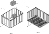
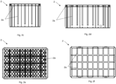
fig. 2a-f , astorage bin 2 is shown in detail. As shown here, thestorage bins 2 comprisesreinforcement bars 2a provided in the bottom surface, the side surfaces and the upper edge defining the opening into the storage bin. Thesereinforcement bars 2a have the purpose of optimizing the strength of the storage bin while keeping the weight of thestorage bin 2 itself low. Moreover, the purpose of thereinforcement bars 2a is to be able to manufacture the storage bins from a relatively cheap material. The present design of the storage bins is determined by the maximum expected load Wmax (i.e. weight) of the storage bins stacked above lowermost storage bin. Hence, the worst condition for thestorage bin 2 is to be the lowermost storage bin in the columns. Infig. 2a , oneproduct item 80 is shown stored in thestorage bin 2 while anotherproduct item 80 is shown above the storage bin. - This again causes the
present storage system 3 to have a limitation in how many storage bins that can be stacked above each other and the weight of each storage bin. The present limits of the storage system infig. 1 is that the maximum weight of each storage bin (i.e. weight ofstorage bin 2 and its product items 80) are 30 kg. and that a maximum of 14storage bins 2 can be stacked above each other percolumn 8. These limitations have also influenced the maximum height of thegrid 15, where the height of thegrid 15 typically corresponds to the height of 14 storage bins. Until recently, these limitations have been sufficient for most storage systems. - Today, overloading of the
storage bins 2 are avoided by computing the maximum number of product items perstorage bin 2, as the weight per product item in most cases are known from the manufacturer. In some storage systems, the weight of thestorage bins 2 can be measured when there is doubt with respect to the 30 kg load limit. The weight of one type of storage bins used in present storage systems is ca 4 - 5 kg. Hence, they may carry up to a weight of 25 - 26 kg. of product items. - The object of the present invention is to provide a storage system and a method for storing storage bins which can handle storage bins with a weight higher than the previously determined maximum weight. Hence, in the above example, the object is to be able to store storage bins with a total weight of more than 30 kg.
- A more specific object is to provide a method and system where the weight of each storage bin including its product items (i.e. weight of the storage bin itself and the product items stored within the storage bin) can be increased without reducing the stack of storage bins in each column.
- Another more specific object of the invention is to increase the height of the grid. In the above example, this means that it is an object to provide a storage system and a method for storing storage bins where more than 14 storage bins can be stacked above each other.
- Another object of the invention is to achieve the above objects of the invention without increasing the cost per storage bin considerably. Another object is that the method and system can be implemented in an already existing storage system without too many modifications.
- The present invention relates to a method for storing product items in storage bins in a storage system comprising a bin storing grid in which storage bins are stored above each other in columns, where the method comprises the following steps:
- inserting product items to or retrieving product items from the respective storage bins at a port;
- determining a weight for each storage bin after one or more product items have been inserted to or retrieved from the storage bin;
- determining a storage position for the storage bin in the bin storing grid based on the weight;
- transporting the storage bin from the port to the determined storage position by means of a vehicle and a bin lift device provided on each vehicle.
- In one aspect, the step of determining the weight for each storage bin comprises the step of weighing the storage bin by means of a weight sensor.
- Alternatively, the step of determining the weight can be performed by estimating the weight based on a predetermined weight of each product item and the number of product items inserted into or retrieved from the storage bin. The predetermined weight could be the weight given by the manufacturer. In yet an alternative, each or all product items could be weighted by means of the weight before they are inserted into or after they have been retrieved from the storage bin.
- The port is often referred to as a supply and/or retrieval port where the product items are supplied to or inserted into the storage bins or retrieved from or picked from the storage bin. In some storage systems, the same port is used for supply and retrieval, while in other storage systems, some ports are used for supply, while other ports are used for retrieval.
- Preferably, the weight sensor is located at the port. Alternatively, the weight sensor is provided as part of the bin lift device of the vehicle. Here, the weight can be calculated based on the current drawn from a motor of the bin lift device during lifting of the respective storage bins.
- Alternatively, the weight for each storage bin can be determined by means of the number of product items within the storage bin, the weight of each product item and the weight of the storage bin itself. As mentioned above, the weight of the storage bin used in present storage systems is 4 - 5 kg.
- In one aspect, the step of determining the storage position further comprises the steps of:
- calculating a total weight for the storage bins presently being stored above the storage bin at the lowermost level of each column;
- selecting the storage position as a position in one of the columns in which the sum of the total weight and the weight of the new storage bin is below the maximum load tolerated by the lowermost storage bin being stored at a lowermost level of the bin storing grid.
- In one aspect, the step of inserting product items to the respective storage bins comprises the steps of:
- overloading a first storage bin with product items;
- underloading a second storage bin with product items;
- In one aspect, the method further comprises the steps of:
- increasing the height of the bin storing grid for at least some columns.
- In one aspect, the method further comprises the steps of:
- storing the total weight for all columns in the grid based on the weight and position of the storage bins;
- updating the total weight of each column each time a storage bin is removed from or added to the respective columns.
- The present invention also relates to a storage system for storing product items in storage bins, where the storage system comprises:
- a bin storing grid in which storage bins are stored above each other in columns;
- a port where product items are inserted into or retrieved from the storage bins;
- a vehicle configured to move horizontally along rails provided on top of the bin storing grid, where the vehicle comprises a bin lifting device for transporting the storage bins horizontally and vertically between the bin storing grid and the port;
- a weight estimation device for estimating the weight of each storage bin after one or more product items have been inserted to or retrieved from the storage bin;
- a storage control system provided in communication with the vehicle and the weight sensor, where the storage control system is configured to determine a storage position for each storage bin based on the weight of the storage bin.
- In one aspect, the weight estimation device is a weight sensor. In one aspect, the weight sensor is located in the port. According to this embodiment, only one or a few sensors are needed in each port.
- In one aspect, the storage control system is configured to:
- calculating a total weight for the storage bins presently being stored above the storage bin at the lowermost level of each column;
- selecting the storage position as a position in one of the columns in which the sum of the total weight and the weight of the storage bin is below the maximum load tolerated by the lowermost storage bin being stored at a lowermost level of the bin storing grid.
- In one aspect, storage control system is configured to store the total weight for all columns in the grid based on the weight and position of the storage bins, and to update the total weight of each column each time a storage bin is removed from or added to the respective columns.
- According to the above, it is achieved that the maximum weight of one storage bin itself is no longer a limitation for the storage system. As mentioned in the introduction, the present maximum weight of each storage bin is 30 kg. With the method and system above, some storage bins may weigh more than 30 kg, i.e. they are overloaded or have a relatively higher weight, for example 35 or 40 kg. This is acceptable, as long as other storage bins in the same column have a weight below 30 kg, i.e. they are underloaded or have a relatively lower weight, for example 25 or 20 kg. Consequently, the maximum load for the storage bin at the lowermost level is not exceeded. It should be noted that this will require the bin lift device of each vehicle, and the vehicle itself, to be able to move a storage bin with a weight of more than 30 kg horizontally and vertically. Present vehicles are capable of this without further modifications.
- The present invention can be implemented in many presently existing storage systems, without the need for replacing all storage bins. As the present storage bins are designed for the maximum load of storage bins stacked above the storage bin when the storage bin is on the lowermost level, the storage bin will also be able to carry product items which causes its weight to be 35 - 40 kg.
- The present invention may also allow the height of the bin storing grid to be increased in storage systems where it is expected that a low percentage of storage bins have a weight of more than 30 kg. It is also possible to provide a storage system with taller columns dedicated to lighter bins and shorter columns for heavier bins. Available volume beneath the shorter columns may then be available for other type of equipment, temporary storage etc.
- In the examples above, the storage bin having a weight of 4 - 5 kg and the load limit of 30 kg are of course used as examples only. The present invention described and discussed herein can be applied to other storage systems as well.
- It should be noted that in most cases, there will be more than one possible storage position for a storage bin presently located at the port. In such a case, other criteria are used to decide which one to use. For example, a storage bin containing frequently picked product items should be stored closer to the port than storage bins containing rarely picked product items.
- Embodiments of the present invention will now be described in detail with reference to the enclosed drawings, where:
-
Fig. 1 illustrates a perspective view of a prior art storage system; -
Fig. 2a illustrates a perspective view of a prior art storage bin from above; -
Fig. 2b illustrates a perspective view of the storage bin from below; -
Fig. 2c illustrates a first side view of the storage bin; -
Fig. 2d illustrates a second side view of the storage bin; -
Fig. 2e illustrates a bottom view of the storage bin; -
Fig. 2f illustrates a top view of a storage bin; -
Fig. 3 illustrates a perspective view of the storage system; -
Fig. 4a illustrates a front view of the storage system; -
Fig. 4b illustrates a side view of the storage system; -
Fig. 4c illustrates a top view of the storage system; -
Fig. 5a illustrates a side view of the port device offig. 3 and4a-c ; -
Fig. 5b illustrates a cross sectional view of the port device along line A-A of fig. Sa; -
Fig. 6 illustrates a two stacks of storage bins with two possible storage positions; -
Fig. 7 illustrates a flow diagram of a method for storing storage bins in a storage system. - It is now referred to
fig. 3 andfig. 4a-c , where astorage system 3 is shown. Thestorage system 3 comprises abin storing grid 15 formed by vertical and horizontal posts connected to each other. On top of thebin storing grid 15, abase 14 forvehicles 1 is formed, where the base 14 haverails 13 for the vehicle wheels. In thebin storing grid 15,storage bins 2 are stored by stacking them above each other incolumns 8. A coordinate system is indicated infig. 3 , with horizontal axis x and y and a vertical axis z. Hence, each storage position P can be referred to as a position defined by its x, y, z coordinate. The level of thelowermost storage bin 2 in eachcolumn 8 is referred to as level z1. In the present example, the level z1 corresponds to the floor of the building in which thegrid 15 is located. - On the floor, adjacent to the
bin storing grid 15, aport 60 is located. At thisport 60, one or more product items may be retrieved from thestorage bin 2, for example based on a picking order. At thisport 60,product items 80 may also be supplied to thestorage bin 2. - In
fig. 5b , the position of theleftmost storage bin 2 is a position to which thevehicle 1 can deliver storage bins or from which thevehicle 1 can retrieve storage bins, while the position of therightmost storage bin 2 is a position in which a person can pick/supply product items 80, provided that thelid 62 is open. - The positions of the storage bins in
fig. 5b are interchanged by rotation of acarrier arm 64 through 180 degrees. - The
port 60 compriseslid 62 which is open when the storage bin is in the picking/supply position (i.e. a person may retrieveproduct items 80 from the storage bin or the person may insertproduct items 80 into the storage bin) and is closed when the storage bin is to be moved between the positions shown infig. 5b . The purpose of thelid 62 is to prevent hands being caught when the storage bins are moved between the positions infig. 5b . Infig. 5b ,reference number 70 denotes a weight sensor for measuring the weight of thestorage bin 2 including the weight of theproduct items 80 stored within thestorage bin 2. Due tocarrier arm 64, there is one weight sensor on each side of the carryingarm 64. It should be noted that if theport 60 were of another type, for example having a conveyor belt or transportation rollers for moving the storage bin, then only oneweight sensor 70 is required. - In these drawings, there are two
vehicles 1, each comprising abin lift device 4. Infig. 4c , these vehicles are indicated asvehicle vehicle 1a is driving over thecolumns 8 in whichstorage bins 2 are stored, while thevehicle 1b is positioned over theport 60 and is ready to retrieve the storage bin 2b from theport 60. - The method according to the invention will now be described with reference to fig.
fig. 6 and7 . Infig. 6 , only twocolumns first column 8a has nine storage bins 2a1, 2a2, 2a3, 2a4, 2a5, 2a6, 2a7, 2a8, 2a9. Here, the letter "a" indicates the column position. In a non-simplified example, the letter "a" will typically be a column referenced by means of x- and y-coordinates. The last number 1 - 9 indicates the height (z-coordinate). Thesecond column 8b has seven storage bins 2b1, 2b2, 2b3, 2b4, 2b5, 2b6, 2b7. - In
fig. 6 , astorage control system 100 is shown as a solid box above thevehicle 1. Thestorage control system 100 is provided in communication with thevehicle 1 and theweight sensor 70. Thestorage control system 100 will typically comprise a database containing the position of each storage bin in thegrid 15 and the content of eachstorage bin 2. In addition, thestorage control system 100 will now know the weight of each storage bin. - The
storage control system 100 may send picking orders to vehicles and persons so that thecorrect storage bin 2 is retrieved from itscolumn 8 and is transported to theport 60 where one ormore product items 80 are picked from the storage bin based on the picking order. In the same way thestorage control system 100 may generate supply orders when a shortage of certain product items are detected. - In
fig. 6 , a total weight Wtot for thestorage bins 2 presently being stored above the storage bin 2a1 at the lowermost level z1 incolumn 8a is indicated as Wtot (8a), while the total weight Wtot for thestorage bins 2 presently being stored above the storage bin 2b1 at the lowermost level z1 ofcolumn 8b is indicated as Wtot (8b). As the weight and the positions for allstorage bins 2 are known for thestorage control system 100, thestorage control system 100 may compute the total weight for allcolumns 8 in thegrid 15. - The maximum load Wmax for the
storage bin 2 being stored at a lowermost level z1 of thebin storing grid 15 is also determined. This will typically be a fixed value, equal for allstorage bins 2, which are set in thestorage control system 100. Of course, if there are several different types ofstorage bins 2, there might be one fixed value for the maximum load Wmax for each type ofstorage bin 2. In such a case, thestorage control system 100 must also know the type of storage bin for all storage bins, for example by means of a type tag readable by a sensor, an identification tag for eachstorage bin 2 readable by a sensor etc. In the present example, the maximum load Wmax is determined as a maximum of 14 fully loaded storage bins, i.e. Wmax = 14 * 30 = 420 kg. - The determination of the maximum load Wmax is considered to be a
first step 110 of the method shown infig. 7 . - It is now referred to
fig. 6 again. Based on a picking order, thevehicle 1 is moving astorage bin 2 containing theproduct item 80 to be picked to theport 60 at position P0. - Then, the
storage bin 2 is moved to position P1, where the content of thestorage bin 2 is accessible for a person or picking robot (not shown) for picking (alternatively supplying) theproduct item 80 from thestorage bin 2. As described above, the movement from the position P0 to the position P1 is performed by theport 60 itself. - Then, the
storage bin 2 is moved to the position P0 again. As described above, the movement from the position P1 to the position P0 is performed by theport 60 itself. At the position P0, thestorage bin 2 is ready for retrieval by means of avehicle 1 again. - After visiting the
port 60, the weight of thestorage bin 2 is measured by the weighingsensor 70, and this weight is registered by thestorage control system 100. This is shown infig. 7 asstep 112. - In
step 114, thestorage control system 100 is calculating the total weight Wtot for the storage bins presently being stored above the storage bin at the lowermost level of each column. In the example above, this equals Wtot (8a) and Wtot (8b). This step may be performed beforestep 112. For example, the total weight Wtot may be stored in a database for each column, where the value for each column is updated each time astorage bin 2 is removed from or added to the stack of storage bins. - In
step 116, the sum of the total weight Wtot and the weight W of thestorage bin 2 currently being at position P0 is determined and compared with the maximum load Wmax for each column. One storage position P or a number of possible storage positions P are calculated as columns with available space, where the sum of the total weight Wtot and the weight W is below the maximum load Wmax. - If there is more than one possible storage position P, then other criteria are used to decide which one to use. For example, a
storage bin 2 containing frequently pickedproduct items 80 should be stored closer to theport 60 thanstorage bins 2 containing rarely pickedproduct items 80. In the example offig. 6 , if thestorage bin 2 at the position P0 contains frequently pickedproduct items 80, then the storage position P incolumn 8b should be selected, as thiscolumn 8b is closer to theport 60. If thestorage bin 2 at the position P0 contains rarely pickedproduct items 80, then the storage position P incolumn 8a should be selected. - In
step 118, one of thevehicles 1 is then controlled to pick up thestorage bin 2 at position P0 and then transport it to the storage position P. - The above method will typically be implemented as software in the
storage control system 100. - It should be noted that it is possible to install the above method in an already existing
storage system 3 where the weight of eachstorage bin 2 is currently not known. The only requirement is that the software of thestorage control system 100 must be updated and that thestorage system 3 is updated with a weight estimation device, typically aweight sensor 70, provided in communication with thestorage control system 100. - The
storage system 3 can be operated as normal or close to normal. Afew columns 8 must be emptied. Thesecolumns 8 are then used initially to receive allstorage bins 2 which have its weight registered by the weight sensor. As more and more storage bins are weighed, more andmore columns 8 are filled withstorage bins 2 which have had its weight registered. In less busy periods, astorage bin 2 which has not been weighed may be transported to the weight sensor to have its weight registered. After a period of time, the weights of all storage bins are registered. - It should be noted that in the description above, the
port 60 is connected directly to thegrid 15. Alternatively, theport 60 may be connected to thegrid 15 at a distance from thegrid 15, for example by means of a conveyor belt assembly or other transporting systems. In such a case, the weight sensor could be implemented as part of such a transporting system. In yet an alternative, theweight sensor 70 could be provided in thevehicle 1 itself, for example by calculating the weight based on the current drawn from a motor of thebin lift device 4 during lifting of the respective storage bins. -
- 1 Vehicle
- 2 Storage bin
- 3 Storage system
- 4 Bin lift device
- 8 Columns
- 13 Rails
- 14 Horizontal base
- 15 Bin storing grid
- 60 Port
- 62 Lid
- 64 Carrier arm
- 70 Weight estimation device/Weight sensor
- 80 Product item
- 100 Storage control system
- P Storage position
- P0 Position
- P1 Position
- z1 Lowermost level
- Aspects and features of the present disclosure are set forth in the following numbered clauses which contain the subject matter of the claims of the parent application as filed.
- 1. Method for storing product items (80) in storage bins (2) in a storage system (3) comprising a bin storing grid (15) in which storage bins (2) are stored above each other in columns (8), where the method comprises the following steps:
- inserting product items (80) to or retrieving product items (80) from the respective storage bins (2) at a port (60);
- determining a weight (W) for each storage bin (2) after one or more product items (80) have been inserted to or retrieved from the storage bin (2);
- determining a storage position (P) for the storage bin (2) in the bin storing grid (15) based on the weight (W);
- transporting the storage bin (2) from the port (60) to the determined storage position (P) by means of a vehicle (1) and a bin lift device (4) provided on each vehicle (1).
- 2. Method according to
clause 1, where the step of determining the weight (W) for each storage bin (2) comprises the step of weighing the storage bin (2) by means of a weight sensor (70). - 3. Method according to
clause - calculating a total weight (Wtot) for the storage bins (2) presently being stored above the storage bin (2) at the lowermost level (z1) of each column (8);
- selecting the storage position (P) as a position in one of the columns (8) in which the sum of the total weight (Wtot) and the weight (W) of the new storage bin (2) is below the maximum load (Wmax) tolerated by the lowermost storage bin (2) being stored at a lowermost level (z1) of the bin storing grid (15).
- 4. Method according to
clause 3, where the step of inserting product items (80) to the respective storage bins (2) comprises the steps of:- overloading a first storage bin (2) with product items (80);
- underloading a second storage bin (2) with product items (80);
- 5. Method according to any one of clauses 1-4, further comprising the steps of:
- increasing the height of the bin storing grid (15) for at least some columns (8).
- 6. Method according to any one of clauses 1-5, further comprising the steps of:
- storing the total weight for all columns (8) in the grid (15) based on the weight (W) and position (P) of the storage bins (2);
- updating the total weight of each column each time a storage bin (2) is removed from or added to the respective columns (8).
- 7. Storage system (3) for storing product items (80) in storage bins (2), where the storage system comprises:
- a bin storing grid (15) in which storage bins (2) are stored above each other in columns (8);
- a port (60) where product items (80) are inserted into or retrieved from the storage bins (2);
- a vehicle (1) configured to move horizontally along rails (13) provided on top of the bin storing grid (15), where the vehicle (1) comprises a bin lifting device (4) for transporting the storage bins (2) horizontally and vertically between the bin storing grid (15) and the port (60);
- a weight estimation device for estimating the weight of each storage bin (2) after one or more product items (80) have been inserted to or retrieved from the storage bin (2);
- a storage control system (100) provided in communication with the vehicle (1) and the weight sensor (70), where the storage control system (100) is configured to determine a storage position (P) for each storage bin (2) based on the weight of the storage bin (2).
- 8. Storage system (3) according to clause 7, where the weight estimation device is a weight sensor (70).
- 9. Storage system according to
clause 8, where the weight sensor (70) is located in the port (60). - 10. Storage system (3) according to
clause 8 or 9, where the storage control system (100) is configured to:- calculating a total weight (Wtot) for the storage bins (2) presently being stored above the storage bin (2) at the lowermost level (z1) of each column (8);
- selecting the storage position (P) as a position in one of the columns (8) in which the sum of the total weight (Wtot) and the weight (W) of the storage bin (2) is below the maximum load (Wmax) tolerated by the lowermost storage bin (2) being stored at a lowermost level (z1) of the bin storing grid (15).
- 11. Storage system (3) according to clause 10, where storage control system (100) is configured to store the total weight for all columns (8) in the grid (15) based on the weight (W) and position (P) of the storage bins (2), and to update the total weight of each column each time a storage bin (2) is removed from or added to the respective columns (8).
Claims (15)
- A method for storing product items (80) in storage bins (2) in a storage system (3), the storage system (3) comprising a bin storing grid (15) in which storage bins (2) are stored above each other in columns (8), and wherein the method comprises:inserting product items (80) to, or retrieving product items (80) from, a storage bin (2) at a port (60);determining a weight (W) for the storage bin (2) after one or more product items (80) have been inserted to, or retrieved from, the storage bin (2);determining a storage position (P) for the storage bin (2) in the bin storing grid (15) based on the weight (W) of the storage bin (2); andtransporting the storage bin (2) from the port (60) to the determined storage position (P) by means of a vehicle (1) and a bin lift device (4) provided on each vehicle (1).
- The method of claim 1, wherein the step of determining the weight (W) for the storage bin (2) comprises weighing the storage bin (2) by means of a weight sensor (70).
- The method of claim 2, wherein:the port (60) is connected to the bin storing grid (15) by means of a transporting system; andthe transporting system comprises the weight sensor (70).
- The method of claim 3, wherein the transporting system is a conveyor belt assembly.
- The method of claim 2, wherein the vehicle (1) comprises the weight sensor (70).
- The method of claim 5, wherein the bin lift device (4) comprises a motor and the step of determining the weight (W) for the storage bin (2) comprises:
calculating the weight for the storage bin (2) based on the current drawn from the motor of the bin lift device (4) during lifting of the storage bin (2). - The method of any preceding claim, wherein the columns (8) comprise at least a first column (8a) and a second column (8b), and wherein the step of determining the storage position (P) further comprises:calculating, for each of the first (8a) and second (8b) columns, a total weight (Wtot) of the storage bins (2) stored above the lowermost storage bin (2) in the respective column, the lowermost storage bin (2) being the storage bin (2) stored at the lowermost level (zl) of the respective column (8); andselecting the storage position (P) as a position in one of the first or second columns (8) in which the sum of the total weight (Wtot) and the weight (W) of the storage bin (2) is below the maximum load (Wmax) tolerated by the lowermost storage bin (2) in the one of the first (8a) or second (8b) columns.
- A storage system (3) for storing product items (80) in storage bins (2), wherein the storage system comprises:a bin storing grid (15) in which storage bins (2) are stored above each other in columns (8);a port (60) where product items (80) are inserted into, or retrieved from, the storage bins (2);a vehicle (1) configured to move horizontally along rails (13) provided on top of the bin storing grid (15), wherein the vehicle (1) comprises a bin lift device (4) for transporting the storage bins (2) horizontally and vertically between the bin storing grid (15) and the port (60);a weight estimation device for estimating the weight of at least one storage bin (2) of the storage bins after one or more product items (80) have been inserted to, or retrieved from, the at least one storage bin (2); anda storage control system (100) provided in communication with the vehicle (1) and the weight sensor (70), wherein the storage control system (100) is configured to determine a storage position (P) for the at least one storage bin (2) based on the weight of the at least one storage bin (2).
- The storage system (3) of claim 8, wherein the weight estimation device is a weight sensor (70).
- The storage system of claim 9, wherein the weight sensor (70) is located in the port (60).
- The storage system of claim 9, wherein:the port (60) is connected to the bin storing grid (15) by means of a transporting system; andthe transporting system comprises the weight sensor (70).
- The storage system of claim 11, wherein the transporting system is a conveyor belt assembly.
- The storage system of claim 9, wherein the vehicle (1) comprises the weight sensor (70).
- The method of claim 13, wherein the bin lift device (4) comprises a motor and estimating the weight of the at least one storage bin (2) comprises:
calculating the weight for the storage bin (2) based on the current drawn from the motor of the bin lift device (4) during lifting of the storage bin (2). - The storage system (3) of any of claims 8 to 14, wherein the columns (8) comprise at least a first column (8a) and at least a second column (8b), and wherein the storage control system (100) is configured to:calculate, for each of the first (8a) and second (8b) columns, a total weight (Wtot) of the storage bins (2) stored above the lowermost storage bin (2) in the respective column, the lowermost storage bin (2) being the storage bin (2) stored at the lowermost level (zl) of the respective column (8); andselect the storage position (P) as a position in one of the first (8a) or second (8b) columns (8) in which the sum of the total weight (Wtot) and the weight (W) of the storage bin (2) is below the maximum load (Wmax) tolerated by the lowermost storage bin (2) in the one of the first (8a) or second (8b) columns.
Applications Claiming Priority (3)
| Application Number | Priority Date | Filing Date | Title |
|---|---|---|---|
| NO20180124A NO344899B1 (en) | 2018-01-26 | 2018-01-26 | Method and system for distributing heavy bins in a storage grid |
| EP19701329.5A EP3743361B1 (en) | 2018-01-26 | 2019-01-21 | System for distributing heavy bins in a storage grid |
| PCT/EP2019/051312 WO2019145237A2 (en) | 2018-01-26 | 2019-01-21 | System for distributing heavy bins in a storage grid |
Related Parent Applications (1)
| Application Number | Title | Priority Date | Filing Date |
|---|---|---|---|
| EP19701329.5A Division EP3743361B1 (en) | 2018-01-26 | 2019-01-21 | System for distributing heavy bins in a storage grid |
Publications (2)
| Publication Number | Publication Date |
|---|---|
| EP4406880A2 true EP4406880A2 (en) | 2024-07-31 |
| EP4406880A3 EP4406880A3 (en) | 2024-10-23 |
Family
ID=65199413
Family Applications (2)
| Application Number | Title | Priority Date | Filing Date |
|---|---|---|---|
| EP24169087.4A Pending EP4406880A3 (en) | 2018-01-26 | 2019-01-21 | System for distributing heavy bins in a storage grid |
| EP19701329.5A Active EP3743361B1 (en) | 2018-01-26 | 2019-01-21 | System for distributing heavy bins in a storage grid |
Family Applications After (1)
| Application Number | Title | Priority Date | Filing Date |
|---|---|---|---|
| EP19701329.5A Active EP3743361B1 (en) | 2018-01-26 | 2019-01-21 | System for distributing heavy bins in a storage grid |
Country Status (5)
| Country | Link |
|---|---|
| US (1) | US11807457B2 (en) |
| EP (2) | EP4406880A3 (en) |
| NO (1) | NO344899B1 (en) |
| PL (1) | PL3743361T3 (en) |
| WO (1) | WO2019145237A2 (en) |
Families Citing this family (9)
| Publication number | Priority date | Publication date | Assignee | Title |
|---|---|---|---|---|
| JP7300468B2 (en) | 2018-06-08 | 2023-06-29 | アタボティックス インコーポレイテッド | A storage and retrieval system that shares a common robotic fleet between storage grids and external work stations |
| EP3983177B8 (en) | 2019-06-11 | 2026-02-11 | Lafayette Systems Canada ULC | Manufacturing system with an interconnected storage structure and manufacturing cells sharing a common robotic fleet |
| NO345796B1 (en) * | 2019-11-22 | 2021-08-09 | Autostore Tech As | Method for distribution of storage containers in an automated storage and retrieval system |
| GB202001297D0 (en) * | 2020-01-30 | 2020-03-18 | Ocado Innovation Ltd | Apparatus and method for charging a load handling device |
| USD1110083S1 (en) | 2020-09-23 | 2026-01-27 | Kaprock Management Llc | Shelving unit |
| US12551032B2 (en) | 2020-09-23 | 2026-02-17 | Kaprock Management Llc | Shelving unit |
| USD1081215S1 (en) | 2020-09-23 | 2025-07-01 | Kaprock Management Llc | Suspended bin rack |
| USD1123466S1 (en) | 2020-09-23 | 2026-04-28 | Kaprock Management Llc | Shelving unit |
| EP4703996A1 (en) * | 2024-08-27 | 2026-03-04 | AutoStore Technology AS | Computer-implemented method for determining a position of a robotic container-handling vehicle |
Citations (1)
| Publication number | Priority date | Publication date | Assignee | Title |
|---|---|---|---|---|
| NO317366B1 (en) | 1999-07-01 | 2004-10-18 | Autostore As | Storage system with remote controlled wagons with two wheelsets and lifting device for operation on rails arranged in cross over columns of storage units separated by vertical profile posts |
Family Cites Families (15)
| Publication number | Priority date | Publication date | Assignee | Title |
|---|---|---|---|---|
| JPH05170552A (en) | 1991-12-19 | 1993-07-09 | Kawasaki Steel Corp | Aluminum nitride substrate having metallized layer and metallization of the substrate |
| DE4203823C2 (en) * | 1992-02-10 | 2001-03-08 | Robert Michaelides | Storage facility |
| JPH0667442U (en) * | 1993-03-08 | 1994-09-22 | 石川島播磨重工業株式会社 | Multi-layer loading equipment for container ships |
| FI105668B (en) * | 1995-10-02 | 2000-09-29 | Cimcorp Oy | picking System |
| DE19925157B4 (en) * | 1999-06-05 | 2007-04-05 | Fritz Potthast | Automated storage system for short and / or medium or long items, preferably for common pallets and / or containers which differ in their dimensions |
| EP1855938B1 (en) | 2005-01-07 | 2010-09-15 | Siemens Industry, Inc. | Automated storage and retrieval system |
| JP5170552B2 (en) * | 2008-09-17 | 2013-03-27 | 株式会社ダイフク | Goods storage facility |
| KR20130006432A (en) * | 2010-02-28 | 2013-01-16 | 이스라엘 에어로스페이스 인더스트리즈 리미티드 | Method of transferring containers and storage system for containers |
| GB201310784D0 (en) * | 2013-06-17 | 2013-07-31 | Ocado Ltd | Systems and Methods for Order Processing |
| GB201409883D0 (en) * | 2014-06-03 | 2014-07-16 | Ocado Ltd | Methods, systems, and apparatus for controlling movement of transporting devices |
| NO344609B1 (en) * | 2016-06-06 | 2020-02-10 | Autostore Tech As | Conveyor with tilt function |
| CN105858046B (en) * | 2016-06-06 | 2018-12-07 | 惠州市普源宏业科技有限公司 | A kind of intelligence row hanging warehousing system |
| GB201610837D0 (en) * | 2016-06-21 | 2016-08-03 | Ocado Innovation Ltd | Robotic cargo handling system and method |
| US20180231973A1 (en) * | 2017-02-16 | 2018-08-16 | Wal-Mart Stores, Inc. | System and Methods for a Virtual Reality Showroom with Autonomous Storage and Retrieval |
| US10647508B2 (en) * | 2017-11-22 | 2020-05-12 | Brandon Eck | Storage station for storing containers transported by unmanned vehicles |
-
2018
- 2018-01-26 NO NO20180124A patent/NO344899B1/en unknown
-
2019
- 2019-01-21 US US16/963,319 patent/US11807457B2/en active Active
- 2019-01-21 EP EP24169087.4A patent/EP4406880A3/en active Pending
- 2019-01-21 EP EP19701329.5A patent/EP3743361B1/en active Active
- 2019-01-21 WO PCT/EP2019/051312 patent/WO2019145237A2/en not_active Ceased
- 2019-01-21 PL PL19701329.5T patent/PL3743361T3/en unknown
Patent Citations (1)
| Publication number | Priority date | Publication date | Assignee | Title |
|---|---|---|---|---|
| NO317366B1 (en) | 1999-07-01 | 2004-10-18 | Autostore As | Storage system with remote controlled wagons with two wheelsets and lifting device for operation on rails arranged in cross over columns of storage units separated by vertical profile posts |
Also Published As
| Publication number | Publication date |
|---|---|
| WO2019145237A3 (en) | 2019-11-07 |
| EP3743361B1 (en) | 2024-04-10 |
| PL3743361T3 (en) | 2024-08-26 |
| US20210371202A1 (en) | 2021-12-02 |
| EP4406880A3 (en) | 2024-10-23 |
| EP3743361A2 (en) | 2020-12-02 |
| US11807457B2 (en) | 2023-11-07 |
| NO20180124A1 (en) | 2019-07-29 |
| WO2019145237A2 (en) | 2019-08-01 |
| NO344899B1 (en) | 2020-06-22 |
Similar Documents
| Publication | Publication Date | Title |
|---|---|---|
| US11807457B2 (en) | System for distributing heavy bins in a storage grid | |
| US12172846B2 (en) | Determining locations at which to store items in a storage facility | |
| JP6762295B2 (en) | Systems and methods for modular storage and management | |
| CN109018803B (en) | Storage control method, system and device for vertical lifting container | |
| CN115667098A (en) | Multi-functional inventory processing station assembly | |
| EP4061746B1 (en) | Automated storage and retrieval system with control system for distribution of storage containers and associated method | |
| CN112384453A (en) | System and method for picking items | |
| US20240109721A1 (en) | Controlling storage locations of products stored in storage containers in an automated storage and retrieval system | |
| US20230365333A1 (en) | A remotely operated vehicle for handling a storage container on a rail system of an automated storage and retrieval system | |
| CN112896903A (en) | Transfer robot-based checking method, transfer robot and checking system | |
| CN112543946A (en) | Warehousing and sorting system and sorting method with improved transfer of goods between two warehousing areas | |
| CN112707074A (en) | Stack storage assembly | |
| JPH0656220A (en) | Carrying-in-out control method of automated warehouse | |
| CN113320872A (en) | Article processing method, device, equipment, system and storage medium | |
| KR102786556B1 (en) | Pallet-based goods loading optimization control apparatus preventing damage to loaded goods boxes | |
| CN117465876B (en) | Goods taking method and device based on intelligent lifting platform | |
| KR102496310B1 (en) | Automatic warehouse system | |
| US20260134385A1 (en) | Determining locations at which to store items in a storage facility | |
| JP7746082B2 (en) | system | |
| AU2024323504A1 (en) | Charging container handling vehicles operating on an automated storage and retrieval system | |
| CN118323701A (en) | Transfer trolley for detecting material sagging and material storage method formed by transfer trolley | |
| JP5776936B2 (en) | Article storage facility and article stacking method in article storage facility |
Legal Events
| Date | Code | Title | Description |
|---|---|---|---|
| PUAI | Public reference made under article 153(3) epc to a published international application that has entered the european phase |
Free format text: ORIGINAL CODE: 0009012 |
|
| STAA | Information on the status of an ep patent application or granted ep patent |
Free format text: STATUS: THE APPLICATION HAS BEEN PUBLISHED |
|
| AC | Divisional application: reference to earlier application |
Ref document number: 3743361 Country of ref document: EP Kind code of ref document: P |
|
| AK | Designated contracting states |
Kind code of ref document: A2 Designated state(s): AL AT BE BG CH CY CZ DE DK EE ES FI FR GB GR HR HU IE IS IT LI LT LU LV MC MK MT NL NO PL PT RO RS SE SI SK SM TR |
|
| REG | Reference to a national code |
Ref country code: DE Ref legal event code: R079 Free format text: PREVIOUS MAIN CLASS: B65G0001137000 Ipc: B65G0001000000 |
|
| PUAL | Search report despatched |
Free format text: ORIGINAL CODE: 0009013 |
|
| AK | Designated contracting states |
Kind code of ref document: A3 Designated state(s): AL AT BE BG CH CY CZ DE DK EE ES FI FR GB GR HR HU IE IS IT LI LT LU LV MC MK MT NL NO PL PT RO RS SE SI SK SM TR |
|
| RIC1 | Information provided on ipc code assigned before grant |
Ipc: B65G 1/137 20060101ALI20240918BHEP Ipc: B65G 1/04 20060101ALI20240918BHEP Ipc: B65G 1/00 20060101AFI20240918BHEP |
|
| STAA | Information on the status of an ep patent application or granted ep patent |
Free format text: STATUS: REQUEST FOR EXAMINATION WAS MADE |
|
| 17P | Request for examination filed |
Effective date: 20241210 |
|
| GRAP | Despatch of communication of intention to grant a patent |
Free format text: ORIGINAL CODE: EPIDOSNIGR1 |
|
| STAA | Information on the status of an ep patent application or granted ep patent |
Free format text: STATUS: GRANT OF PATENT IS INTENDED |
|
| INTG | Intention to grant announced |
Effective date: 20260217 |
|
| RIC1 | Information provided on ipc code assigned before grant |
Ipc: B65G 1/00 20060101AFI20260209BHEP Ipc: B65G 1/04 20060101ALI20260209BHEP Ipc: B65G 1/137 20060101ALI20260209BHEP |
|
| RAP3 | Party data changed (applicant data changed or rights of an application transferred) |
Owner name: AUTOSTORE TECHNOLOGY AS |