EP4406818A1 - Straddled vehicle - Google Patents
Straddled vehicle Download PDFInfo
- Publication number
- EP4406818A1 EP4406818A1 EP23211117.9A EP23211117A EP4406818A1 EP 4406818 A1 EP4406818 A1 EP 4406818A1 EP 23211117 A EP23211117 A EP 23211117A EP 4406818 A1 EP4406818 A1 EP 4406818A1
- Authority
- EP
- European Patent Office
- Prior art keywords
- vehicle
- switch
- storage case
- receiver
- straddled
- Prior art date
- Legal status (The legal status is an assumption and is not a legal conclusion. Google has not performed a legal analysis and makes no representation as to the accuracy of the status listed.)
- Granted
Links
Images



Classifications
-
- B—PERFORMING OPERATIONS; TRANSPORTING
- B62—LAND VEHICLES FOR TRAVELLING OTHERWISE THAN ON RAILS
- B62J—CYCLE SADDLES OR SEATS; AUXILIARY DEVICES OR ACCESSORIES SPECIALLY ADAPTED TO CYCLES AND NOT OTHERWISE PROVIDED FOR, e.g. ARTICLE CARRIERS OR CYCLE PROTECTORS
- B62J9/00—Containers specially adapted for cycles, e.g. panniers or saddle bags
- B62J9/20—Containers specially adapted for cycles, e.g. panniers or saddle bags attached to the cycle as accessories
- B62J9/24—Containers specially adapted for cycles, e.g. panniers or saddle bags attached to the cycle as accessories on specially adapted racks, e.g. for top or side cases
-
- B—PERFORMING OPERATIONS; TRANSPORTING
- B62—LAND VEHICLES FOR TRAVELLING OTHERWISE THAN ON RAILS
- B62J—CYCLE SADDLES OR SEATS; AUXILIARY DEVICES OR ACCESSORIES SPECIALLY ADAPTED TO CYCLES AND NOT OTHERWISE PROVIDED FOR, e.g. ARTICLE CARRIERS OR CYCLE PROTECTORS
- B62J9/00—Containers specially adapted for cycles, e.g. panniers or saddle bags
- B62J9/30—Containers specially adapted for cycles, e.g. panniers or saddle bags characterised by locking arrangements, e.g. top case locks integrated in a vehicle central locking system
-
- G—PHYSICS
- G07—CHECKING-DEVICES
- G07C—TIME OR ATTENDANCE REGISTERS; REGISTERING OR INDICATING THE WORKING OF MACHINES; GENERATING RANDOM NUMBERS; VOTING OR LOTTERY APPARATUS; ARRANGEMENTS, SYSTEMS OR APPARATUS FOR CHECKING NOT PROVIDED FOR ELSEWHERE
- G07C9/00—Individual registration on entry or exit
- G07C9/00174—Electronically operated locks; Circuits therefor; Nonmechanical keys therefor, e.g. passive or active electrical keys or other data carriers without mechanical keys
- G07C9/00309—Electronically operated locks; Circuits therefor; Nonmechanical keys therefor, e.g. passive or active electrical keys or other data carriers without mechanical keys operated with bidirectional data transmission between data carrier and locks
Definitions
- the present invention relates to a straddled vehicle.
- a conventional straddled vehicle is configured to change a locking state of the storage case by detecting an identification signal from a portable transmitter.
- the straddled vehicle includes a receiver and a switch.
- the receiver recognizes the portable transmitter by receiving the identification signal from the portable transmitter with wireless communication.
- the storage case is unlocked by operating the switch in a state where the portable transmitter is recognized. Alternatively, the storage case is locked by operating the switch in the state where the portable transmitter is recognized.
- the straddled vehicle disclosed in PCT International Publication No. WO2020/174544 includes a communication unit which communicates with a smart key.
- the communication unit recognizes the smart key, on/off of a main switch becomes effective and a trunk case is unlocked by turning on the main switch.
- the receiver recognizes the portable transmitter by receiving the identification signal from the portable transmitter.
- a detection range in which the receiver detects the identification signal is limited to a small range, for example, the small range from 1m to 2m from the receiver.
- the receiver it is difficult for the receiver to recognize the portable transmitter in case that the receiver is disposed on a rear portion of the vehicle and the portable transmitter is positioned at a front side of the vehicle.
- An object of the present invention is to provide a straddled vehicle which can easily recognize a portable transmitter positioned around the straddled vehicle and can improve accessibility to a storage case.
- said object is solved by a straddled vehicle having the features of independent claim 1.
- said object is also solved by a straddled vehicle having the features of independent claim 16. Preferred embodiments are laid down in the dependent claims.
- a straddled vehicle is configured to mount a storage case.
- the straddled vehicle is configured to change a locking state of the storage case by detecting an identification signal from a portable transmitter.
- the straddled vehicle a vehicle body, a seat, a bracket, a receiver and a switch.
- the seat is provided on the vehicle body.
- the bracket is disposed at a rear side than the seat.
- the bracket is provided on the vehicle body to mount the storage case to the vehicle body.
- the receiver is mounted to the vehicle body at a lower side than the seat.
- the receiver is configured to receive the identification signal from the portable transmitter.
- the switch is mounted to the vehicle body at the rear side than the receiver and at a front side than the bracket. The switch is configured to be operated to change the locking state of the storage case.
- the receiver can easily recognize the portable transmitter even if the portable transmitter is positioned at the front side than the straddled vehicle or at the rear side than the straddled vehicle, since the receiver is mounted to the vehicle body at the lower side than the seat.
- the receiver can easily recognize the portable transmitter even if the rider approaches the switch to operate the switch, since the switch is mounted to the vehicle body at the rear side than the receiver and at the front side than the bracket.
- the rider can easily access the storage case after the rider operates the switch.
- the straddled vehicle which can easily recognize the portable transmitter positioned around the straddled vehicle and can improve accessibility to the storage case, is provided.
- the vehicle body can have a vehicle center line extending in a vehicle longitudinal direction.
- the switch is mounted to the vehicle body at one side in a vehicle width direction orthogonal to the vehicle center line.
- the receiver can easily recognize the portable transmitter when the rider approaches the switch.
- the receiver can be mounted to the vehicle body at the one side in the vehicle width direction. In this configuration, the receiver can more easily recognize the portable transmitter when the rider approaches the switch, since the receiver is mounted to the vehicle body at the same side as the switch.
- the straddled vehicle can further comprise a key cylinder.
- the key cylinder is configured to open and close the seat.
- the key cylinder is mounted to the vehicle body at the one side in the vehicle width direction. In this configuration, the rider can easily open and close the seat after the rider access the storage case, since the key cylinder is mounted to the vehicle body at the same side as the switch. In addition, the rider can easily access the storage case after the rider opens and closes the seat.
- the straddled vehicle can further comprise a rear cover.
- the rear cover is mounted to the vehicle body at the rear side than the seat.
- the switch is mounted to a side surface of the rear cover. In this configuration, the rider can easily access the switch.
- the straddled vehicle can further comprise a rear cover.
- the rear cover is mounted to the vehicle body at the rear side than the seat.
- the switch is mounted to an upper surface of the rear cover. In this configuration, the rider can easily access the switch.
- the vehicle body can include a first rear frame and a second rear frame.
- the first rear frame supports the seat and a second rear frame.
- the second rear frame is disposed at the lower side than the first rear frame and is connected to a rear portion of the first rear frame.
- the receiver is disposed at an upper side than the second rear frame. In this configuration, the receiver can easily recognize the portable transmitter, since the receiver is disposed at an upper side than the second rear frame.
- the receiver can be disposed at the lower side than the first rear frame. In this configuration, the receiver can easily recognize the portable transmitter, since the receiver is disposed at the lower side than the first rear frame.
- the straddled vehicle can further comprise a tandem step.
- the tandem step includes a mounting portion mounted to the vehicle body.
- the switch is disposed at the rear side than the mounting portion of the tandem step. In this configuration, it is possible to prevent a passenger from contacting the switch in a state where the rider and the passenger ride on the straddled vehicle.
- the vehicle body can include a first rear frame and a second rear frame.
- the first rear frame supports the seat and a second rear frame.
- the second rear frame is disposed at the lower side than the first rear frame and is connected to a rear portion of the first rear frame.
- At least a portion of the switch is disposed at the upper side than the second rear frame. In this configuration, the rider can easily operate the switch, since the at least a portion of the switch is disposed at the upper side than the second rear frame.
- the straddled vehicle can further comprise the storage case.
- the storage case is mounted to the bracket. In this configuration, the rider can easily access the storage case after the rider operates the switch.
- the switch can be spaced apart from the storage case so as not to overlap the storage case in a vehicle side view. In this configuration, the straddled vehicle can improve accessibility to the storage case without reducing usability of the switch.
- the straddled vehicle can further comprise a controller.
- the controller is configured to authenticate the portable transmitter based on the identification signal.
- the storage case includes a signal receiving unit.
- the signal receiving unit is configured to receive a command signal for changing the locking state from the controller.
- the controller is configured to transmit the command signal to the signal receiving unit when the switch is operated in a state where the portable transmitter is authenticated.
- the controller authenticates the portable transmitter based on the identification signal from the portable transmitter and the locking state of the storage case is changed based on the command signal from the controller. Thereby, the locking state of the storage case can be easily changed by the controller.
- the switch can be configured to be operated to change the locking state of the storage case at least from a locked state to an unlocked state.
- the locking state of the storage case includes the locked state and the unlocked state.
- the locking state of the storage case can be changed from the locked state to the unlocked state by operating the switch.
- the vehicle body can have a vehicle center line extending in a longitudinal direction and a mounting surface on which the switch is mounted.
- the mounting surface inclines inward in a vehicle width direction orthogonal to the vehicle center line as the mounting surface goes toward the lower side. In this configuration, it is possible to prevent the passenger from contacting the switch in a state where the rider and the passenger ride on the straddled vehicle.
- a straddled vehicle is configured to mount a storage case.
- the straddled vehicle is configured to change a locking state of the storage case by detecting an identification signal from a portable transmitter.
- the straddled vehicle a vehicle body, a seat, a bracket, a receiver and a switch holder.
- the seat is provided on the vehicle body.
- the bracket is disposed at a rear side than the seat.
- the bracket is provided on the vehicle body to mount the storage case to the vehicle body.
- the receiver is mounted to the vehicle body at a lower side than the seat. The receiver is configured to receive the identification signal from the portable transmitter.
- the switch holder configured to hold a switch operated to change the locking state of the storage case.
- the switch holder is mounted to the vehicle body at the rear side than the receiver and at a front side than the bracket.
- the receiver can easily recognize the portable transmitter even if the portable transmitter is positioned at the front side than the straddled vehicle or at the rear side than the straddled vehicle, since the receiver is mounted to the vehicle body at the lower side than the seat.
- the receiver can easily recognize the portable transmitter even if the rider approaches the switch to operate the switch, since the switch holder is mounted to the vehicle body at the rear side than the receiver and at the front side than the bracket.
- the rider can easily access the storage case after the rider operates the switch.
- the straddled vehicle which can easily recognize the portable transmitter positioned around the straddled vehicle and can improve accessibility to the storage case, is provided.
- the straddled vehicle which can easily recognize the portable transmitter positioned around the straddled vehicle and can improve accessibility to the storage case, is provided.
- FIG. 1 is a side view of the straddled vehicle 1 according to the embodiment.
- the straddled vehicle 1 includes a vehicle frame 2 (an example of a vehicle body), a steering device 3, a fuel tank 4, a rider seat 5 (an example of a seat), a power unit 6, a front wheel 7, a swing arm 8 and a rear wheel 9.
- the straddled vehicle 1 includes a tandem step 10 and a key cylinder 11.
- a front side of a rider (a front side in FIG. 1 ), a rear side of the rider (a rear side in FIG. 1 ), a left side of the rider, and a right side of the rider respectively corresponds to each of front, rear, left and right directions of the straddled vehicle 1 in a state where the rider is seated on the rider seat 5.
- An upper side of the rider corresponds to an upper direction of the straddled vehicle 1.
- a downward direction of the straddled vehicle 1 (a downward side in FIG. 1 ) is a direction opposite to the upward direction of the straddled vehicle 1.
- the downward direction of the straddled vehicle 1 is a direction in which gravity acts on the straddled vehicle 1.
- a vehicle front view indicates a state where a front portion of the straddled vehicle 1 is viewed from the front side thereof.
- a vehicle side view indicates a state where a side surface of the straddled vehicle 1 is viewed from the left side thereof or the right side thereof.
- a vehicle rear view indicates a state where a rear portion of the straddled vehicle 1 is viewed from the rear side thereof.
- a vehicle upper view indicates a state where an upper portion of the straddled vehicle 1 is viewed from the upper side thereof.
- the straddled vehicle for example, the vehicle frame 2, has a vehicle center plane H extending in a vehicle front-rear direction.
- the vehicle center plane H extends in the front-rear direction and a vehicle vertical direction.
- the vehicle center plane H passes through a head pipe 12 in the front-rear direction.
- the vehicle center plane H passes through a center of the head pipe 12 in the front-rear direction in the vehicle upper view.
- the vehicle center plane H forms a vehicle center line extending in the front-rear direction in the vehicle upper view.
- a vehicle width direction W is defined as a direction orthogonal to the vehicle center plane H.
- the vehicle width direction W corresponds to a vehicle left-right direction.
- the vehicle frame 2 includes a head pipe 12, a main frame 13, and a rear frame 14.
- the main frame 13 is connected to the head pipe 12.
- the main frame 13 includes a pair of main frames 20, 21.
- the pair of main frames 20, 21 extend rearward from the head pipe 12 and are spaced apart from each other in the vehicle width direction W.
- FIG. 1 shows the left main frame 20.
- the right main frame 21 is disposed as a mirror image of the left main frame 20 with respect to the vehicle center plane H.
- a reference number 21 of the right main frame is indicated in a bracket with the reference number 20 of the left main frame.
- the rear frame 14 is connected to the main frame 13.
- the rear frame 14 includes a pair of rear frames 24, 25.
- FIG. 1 shows the left rear frame 24.
- the right rear frame 25 is disposed as a mirror image of the left rear frame 24 with respect to the vehicle center plane H.
- the right rear frame 25 is shown in brackets with the left rear frame 24.
- the left rear frame 24 and the right rear frame 25 are disposed at a lower side than the rider seat 5.
- the pair of rear frames 24, 25 are respectively connected to the pair of main frames 20, 21.
- the left rear frame 24 and the right rear frame 25 support the rider seat 5.
- the left rear frame 24 includes a first left rear frame 26 and a second left rear frame 27.
- the first left rear frame 26 supports the rider seat 5.
- the first left rear frame 26 is connected to the left main frame 20.
- the second left rear frame 27 supports the first left rear frame 26 (see FIG. 5 ).
- the second left rear frame 27 is disposed at the lower side than the first left rear frame 26.
- the second left rear frame 27 is connected to the left main frame 20 and a rear portion of the first left rear frame 26.
- the tandem step 10 is mounted to the second left rear frame 27 via an arm portion 28.
- the tandem step 10 is swingably mounted to the arm portion 28.
- the tandem step 10 is swingably mounted to the arm portion 28 via a swing shaft 29 (an example of a mounting portion).
- the right rear frame 25 is disposed as a mirror image of the left rear frame 24 with respect to the vehicle center plane H (see FIG. 6 ). Except for this point, the configuration of the right rear frame 25 is the same as the configuration of the left rear frame 24.
- the right rear frame 25 includes a first right rear frame 30 and a second right rear frame 31.
- the reference number 30 of the first right rear frame and the reference number 31 of the second right rear frame are respectively indicated in brackets with the reference number 26 of the first left rear frame and a reference 27 number of the second left rear frame.
- the first right rear frame 30 is spaced apart from the first left rear frame 26 in the vehicle width direction W (see FIG. 6 ).
- the first right rear frame 30 supports the rider seat 5 with the first left rear frame 26.
- the first right rear frame 30 is connected to the right main frame 21.
- the second right rear frame 31 is spaced apart from the second left rear frame 27 in the vehicle width direction W (see FIG. 6 ).
- the second right rear frame 31 supports the first right rear frame 30 (see FIG. 5 ).
- the second right rear frame 31 is disposed at the lower side than the first right rear frame 30.
- the second right rear frame 31 is connected to the right main frame 21 and a rear portion of the first right rear frame 30.
- the steering device 3 is rotatably supported on the head pipe 12.
- the steering device 3 rotatably supports the front wheel 7.
- the steering device 3 includes a steering shaft 32, a handle member 33, a front fork 34, an upper bracket 35 and a lower bracket 36.
- the steering shaft 32 is inserted into the head pipe 12.
- the handle member 33 is disposed at an upper side than the head pipe 12.
- the handle member 33 is connected to the steering shaft 32.
- the handle member 33 extends in the left-right direction.
- the front fork 34 is connected to steering shaft 32 via the upper bracket 35 and the lower bracket 36.
- the front fork 34 rotatably supports the front wheel 7.
- the fuel tank 4 is disposed at a rear side than the head pipe 12.
- the fuel tank 4 is disposed at a front side than the rider seat 5.
- the fuel tank 4 is disposed at the upper side than the main frame 13 and is supported by the main frame 13.
- the rider seat 5 is provided on the vehicle frame 2.
- the rider seat 5 is supported by the rear frame 14.
- the rider seat 5 is supported by the first left rear frame 26 and the first right rear frame 30.
- the rider seat 5 is disposed at the upper side than the rear frame 14.
- the rider seat 5 is disposed at the rear side than the fuel tank 4.
- a tandem seat 37 is disposed at the rear side than the rider seat 5.
- the rider seat 5 is disposed between the fuel tank 4 and the tandem seat 37.
- the tandem seat 37 is supported by the rear frame 14.
- the tandem seat 37 is supported by the first left rear frame 26 and the first right rear frame 30.
- a grab bar 38 is disposed around a rear portion of the tandem seat 37.
- the grab bar 38 surround the rear, left, and right portions of tandem seat 37.
- the grab bar 38 is supported by the rear frame 14.
- the key cylinder 11 is configured to open and close the rider seat 5.
- the key cylinder 11 is disposed at one side in the vehicle width direction W.
- the key cylinder 11 is disposed at the left side in the vehicle width direction W.
- the key cylinder 11 is disposed at the lower side than the rider seat 5.
- the key cylinder 11 is disposed at the front side than a switch 52 which is described later.
- the key cylinder 11 is mounted to the vehicle frame 2.
- the key cylinder 11 is mounted to a left rear cover 41 which is described later.
- the left rear cover 41 is mounted to the first left rear frame 26 and the first right rear frame 30.
- the key cylinder 11 is mounted to the first left rear frame 26 and the first right rear frame 30 via the left rear cover 41.
- the power unit 6 is disposed at the lower side than the fuel tank 4.
- the power unit 6 is supported by main frame 13.
- the power unit 6 includes an internal combustion engine.
- the rear wheel 9 is supported by main frame 13 via the swing arm 8.
- the rear wheel 9 is rotatably supported by the swing arm 8.
- the swing arm 8 is swingably supported by the main frame 13.
- the straddled vehicle 1 includes a main cowl 22 and a rear cover 23.
- the main cowl 22 is disposed at the front side than the head pipe 12, at the left side than the head pipe 12 and at the right side of the head pipe 12.
- the main cowl 22 is mounted to the main frame 13.
- the main cowl 22 is disposed at the front side than the handle member 33, at the lateral side than a front portion of the fuel tank 4, at the lower side than the fuel tank 4 and at the lower side than the rider seat 5.
- the main cowl 22 covers an upper portion of the left main frame 20, an upper portion of the right main frame 21, a front portion of the left rear frame 24 and a front portion of the right rear frame 25.
- the rear cover 23 is disposed at the lower side than the rider seat 5.
- the rear cover 23 is disposed at the rear side than the rider seat 5.
- the rear cover 23 is disposed at the lower side than the rider seat 5 and at the lower side than the tandem seat 37.
- the rear cover 23 includes a pair of rear covers 41, 42, for example, the left rear cover 41 and a right rear cover 42.
- the right rear cover 42 is disposed as a mirror image of the left rear cover 41 with respect to the vehicle center plane H.
- the reference number 42 of the right rear cover is indicated in brackets with the reference number 41 of the left rear cover.
- the left rear cover 41 covers middle and rear portions of the left rear frame 24, for example, the middle and rear portions of the first left rear frame 26 and the second left rear frame 27.
- the left rear cover 41 is mounted to the first left rear frame 26.
- the left rear cover 41 includes a first side case mounting hole 41a and a switch mounting surface 41b.
- the first side case mounting hole 41a is a hole which is used to mount a left-side case 44a, which is described later, to the first left rear frame 26.
- the switch 52 for example, a switch holder 43 which is described later, is provided on the switch mounting surface 41b.
- the switch mounting surface 41b forms an outer surface of the left rear cover 41 so as to incline inward in the vehicle width direction W as the switch mounting surface 41b goes toward the lower side.
- the right rear cover 42 covers middle and rear portions of the right rear frame 25, for example, the middle and rear portions of the first right rear frame 30 and the second right rear frame 31.
- the right rear cover 42 is mounted to the first right rear frame 30.
- the right rear cover 42 includes a second side case mounting hole 42a.
- the second side case mounting hole 42a is a hole which is used to mount a right-side case 44b, which will be described late, to the first right rear frame 30.
- the straddled vehicle 1 includes the switch holder 43.
- the switch holder 43 is configured to hold the switch 52.
- the switch holder 43 is a hole which holds the switch 52.
- the switch holder 43 is disposed at one side in the vehicle width direction W. In this embodiment, the switch holder 43 is disposed at the left side in the vehicle width direction W. The switch holder 43 is disposed at the upper side than the second left rear frame 27. The switch holder 43 is disposed at the lower side than the first left rear frame 26.
- the switch holder 43 is disposed at the rear side than a receiver 51 and at the front side than a bracket 45.
- the receiver 51 and the bracket 45 are described later.
- the switch holder 43 is disposed at the rear side than the receiver 51 in the vehicle side view and at the front side than a first side bracket 47 which is described later in the vehicle side view.
- the switch holder 43 is disposed at the rear side than the receiver 51 in the vehicle side view and at the front side than a second side bracket 48 which is described later in the vehicle side view.
- the switch holder 43 is provided on a side surface of the left rear cover 41 or an upper surface of the left rear cover 41. In this embodiment, the switch holder 43 is provided on the side surface of the left rear cover 41. An example in which the switch holder 43 is provided on the upper surface of the left rear cover 41 is indicated by a dashed line using the reference number "43'" in FIG. 4 .
- the left rear cover 41 is mounted to the first left rear frame 26.
- the switch holder 43 is provided on the switch mounting surface 41b of the left rear cover 41. In other words, the switch holder 43 is mounted to the first left rear frame 26 via the left rear cover 41.
- the straddled vehicle 1 is configured to mount a storage case 44.
- the straddled vehicle 1 includes the storage case 44 shown in FIGS. 1-3 and the bracket 45 shown in FIGS. 4-6 .
- the storage case 44 is a component of the straddled vehicle 1 is described, but the storage case 44 may not be the component of the straddled vehicle 1.
- the storage case 44 is configured to accommodate articles.
- the storage case 44 is configured to open and close for accommodating the articles and taking out the articles.
- the storage case 44 includes a locking mechanism 44e shown in FIG. 7 .
- the locking mechanism 44e is configured to change the locking state.
- the locking state includes an unlocked state which permits opening and closing of the storage case 44 and a locked state which restricts opening and closing of the storage case 44.
- the storage case 44 shown in FIGS. 1-3 is detachably mounted to the vehicle frame 2 via the bracket 45 shown in FIGS. 4-6 .
- the storage case 44 includes the left-side case 44a, the right-side case 44b, and a top case 44c.
- the left-side case 44a is disposed at the left side than the vehicle frame 2 at the rear portion of the vehicle frame 2.
- the left-side case 44a is disposed at the left side than the first left rear frame 26.
- the right-side case 44b is disposed at the right side than the vehicle frame 2 at the rear portion of the vehicle frame 2.
- the right-side case 44b is disposed at the right side than the first right rear frame 30.
- the top case 44c is disposed at the rear side than the rider seat 5.
- the top case 44c is disposed at the rear side than the tandem seat 37.
- the top case 44c is disposed at the upper side than the vehicle frame 2 at the rear portion of the vehicle frame 2.
- the top case 44c is disposed at the upper side than the rear end of the first left rear frame 26 and the rear end of the first right rear frame 30.
- the bracket 45 shown in FIGS. 4 to 6 is used to mount the storage case 44 to the vehicle frame 2. As shown in FIGS. 5 and 6 , the bracket 45 is provided on the vehicle frame 2, for example, the first left rear frame 26 and the first right rear frame 30.
- the bracket 45 includes the first side bracket 47 and the second side bracket 48.
- the bracket 45 includes a first rear bracket 49 and a second rear bracket 50.
- the first side bracket 47 shown in FIGS. 5 and 6 is used to mount the left-side case 44a. As shown in FIG. 4 , the first side bracket 47 is disposed at the rear side than the rider seat 5. The first side bracket 47 is disposed at the lower side than the tandem seat 37.
- the first side bracket 47 is mounted to the rear portion of the first left rear frame 26.
- the left-side case 44a is detachably mounted to the first side bracket 47 via the first side case mounting hole 41a shown in FIG. 4 .
- the second side bracket 48 shown in FIGS. 5 and 6 is used to mount the right-side case 44b. As shown in FIG. 4 , the second side bracket 48 is disposed at the rear side than the rider seat 5. The second side bracket 48 is disposed at the lower side than the tandem seat 37.
- the second side bracket 48 is mounted to the rear portion of the first right rear frame 30.
- the right-side case 44b is detachably mounted to the second side bracket 48 via the second side case mounting hole 42a shown in FIG. 4 .
- the first rear bracket 49 and the second rear bracket 50 shown in FIGS. 5 and 6 are used to mount the top case 44c.
- the first rear bracket 49 is mounted to the rear end of the first left rear frame 26.
- the second rear bracket 50 is mounted to the rear end of the first right rear frame 30.
- the top case 44c is detachably mounted to the first rear bracket 49 and the second rear bracket 50 via a stay or stays (not shown).
- the straddled vehicle 1 includes the receiver 51, the switch 52 and a battery 53.
- the straddled vehicle 1 includes a first vehicle speed sensor 54, a second vehicle speed sensor 55 and a controller 61.
- the receiver 51 is disposed at one side in the vehicle width direction W. In this embodiment, the receiver 51 is disposed at the left side in the vehicle width direction W.
- the receiver 51 is mounted to the vehicle frame 2, for example, the first left rear frame 26 and/or the first right rear frame 30.
- the receiver 51 is disposed at the lower side than the rider seat 5.
- the receiver 51 is disposed at the lower side than the first left rear frame 26.
- the receiver 51 is disposed at the upper side than second left rear frame 27. In other words, the receiver 51 is disposed between the first left rear frame 26 and the second left rear frame 27 in the vertical direction.
- the receiver 51 is configured to receive an identification signal from a portable transmitter M.
- the receiver 51 receives the identification signal, which is used to identify the portable transmitter M, from the portable transmitter M.
- the receiver 51 receives the identification signal from the portable transmitter M according to distance from the portable transmitter M.
- the receiver 51 receives the identification signal from the portable transmitter M, when the distance between the portable transmitter M and the receiver 51 is smaller than or equal to a predetermined distance. In this case, the receiver 51 transmits the identification signal to controller 61. The receiver 51 does not receive the identification signal from the portable transmitter M, when the distance between the portable transmitter M and the receiver 51 is larger than the predetermined distance. In this case, the receiver 51 does not transmit the identification signal to controller 61.
- the switch 52 shown in FIGS. 1 and 4 is disposed at one side in the vehicle width direction W.
- the switch 52 is disposed at the left side in the vehicle width direction W.
- the switch 52 is disposed at the rear side than the receiver 51 and at the front side than the bracket 45.
- the switch 52 is disposed at the rear side than the receiver 51 and at the front side than the first side bracket 47 in the vehicle side view.
- the switch 52 is disposed at the rear side than the receiver 51 and at the front side than the second side bracket 48 in the vehicle side view.
- the switch 52 is spaced apart from the storage case 44 so as not to overlap the storage case 44 in the vehicle side view.
- the switch 52 is spaced apart from the left-side case 44a so as not to overlap the left-side case 44a in the vehicle side view.
- the switch 52 is spaced apart from the left-side case 44a and the right-side case 44b so as not to overlap the left-side case 44a and the right-side case 44b in the vehicle side view.
- the switch 52 is disposed at the upper side than the second left rear frame 27.
- the switch 52 is disposed at the upper side than the second left rear frame 27
- a portion of the switch 52 can be disposed at the lateral side than the second left rear frame 27.
- the switch 52 is disposed at the rear side than the swing shaft 29 of the tandem step 10.
- the switch 52 is mounted to the side surface of the left rear cover 41 or the upper surface of the left rear cover 41. In this embodiment, the switch 52 is mounted to the side surface of the left rear cover 41. An example in which the switch 52 is provided on the upper surface of the left rear cover 41 is indicated by a dashed line using the reference number "52'" in FIG. 4 .
- the switch 52 is mounted to the switch holder 43 (the hole) of the left rear cover 41.
- the switch 52 is elastically engaged with the switch holder 43 (the hole).
- the left rear cover 41 is mounted to the first left rear frame 26. In other words, the switch 52 is mounted to the first left rear frame 26 via the left rear cover 41.
- the switch 52 is operated to change the locking state of the storage case 44.
- the switch 52 is operated to change the locking state of the left-side case 44a and the right-side case 44b from at least the locking state to the unlocking state.
- the switch 52 changes the locking state of the left-side case 44a and the right-side case 44b from one of the locked state and the unlocked state to the other of the locked state and the unlocked state.
- the switch 52 includes a lock button 52a which is used to lock the storage case 44 and an unlock button 52b which is used to unlock the storage case 44.
- the switch 52 transmits a lock signal to the controller 61 when the lock button 52a is pressed.
- the switch 52 transmits an unlock signal to the controller 61 when the unlock button 52b is pressed.
- the battery 53 shown in FIGS. 1 and 4 supplies power to the receiver 51, the first vehicle speed sensor 54, the second vehicle speed sensor 55 and the controller 61.
- Each of the switch 52 and the storage case 44 contain a battery for operating the switch 52 and a signal receiving unit 44d which is described later.
- the battery 53 is disposed at the lower side than the rider seat 5.
- the battery 53 is disposed between the rider seat 5 and the receiver 51 in the vertical direction.
- the battery 53 is disposed between the rider seat 5 and the second left rear frame 27 in the vertical direction.
- the battery 53 is mounted to the first left rear frame 26.
- the first vehicle speed sensor 54 is mounted to a tip portion of the left front fork 34 which is included in the front fork 34.
- the first vehicle speed sensor 54 detects a rotational speed of the front wheel 7.
- the first vehicle speed sensor 54 transmits a first rotational speed signal corresponding to the rotational speed of the front wheel 7 to the controller 61.
- the second vehicle speed sensor 55 is mounted to a tip portion of the left swing arm 8 which is included in the swing arm 8.
- the second vehicle speed sensor 55 detects a rotational speed of the rear wheel 9.
- the second vehicle speed sensor 55 transmits a second rotational speed signal corresponding to the rotation speed of the rear wheel 9 to the controller 61.
- the controller 61 includes a processor 61a and a memory 61b.
- the controller 61 can further include an external storage device and an auxiliary storage device such as a hard disk and/or SSD (Solid State Drive).
- the processor 61a includes at least one CPU (Central Processing Unit). In this embodiment, an example in which the processor 61a includes one CPU is described. In this embodiment, an example in which the processor 61a includes one CPU is described, but the processor 61a includes a plurality of CPUs.
- CPU Central Processing Unit
- the processor 61a controls a lock changing system, which will be described later, based on control program recorded in the memory 61b.
- the processor 61a reads control data from the memory 61b and records the control data in the memory 61b.
- the memory 61b includes a volatile memory such as RAM (Random Access Memory).
- the memory 61b includes a non-volatile memory such as ROM (Read Only Memory).
- the memory 61b records the control program and the control data which is used in executing the lock changing system.
- the controller 61 shown in FIG. 1 is mounted to the main frame 13.
- the controller 61 is disposed at the front side than the fuel tank 4.
- the portable transmitter M, the switch 52, the receiver 51, the signal receiving unit 44d of the storage case 44 which will be described later and the controller 61 are connected to each other by wireless communication.
- the controller 61, the battery 53, the first vehicle speed sensor 54 and the second vehicle speed sensor 55 are connected to each other by wire communication.
- the controller 61, the battery 53, the first vehicle speed sensor 54 and the second vehicle speed sensor 55 can be connected to each other by the wireless communication.
- each of the left-side case 44a and the right-side case 44b includes the signal receiving unit 44d.
- the top case 44c does not have the signal receiving unit 44d is described, but the top case 44c can have the signal receiving unit 44d.
- the signal receiving unit 44d is supplied with power from the battery which is provided on each of the left-side case 44a, the right-side case 44b and the top case 44c.
- the signal receiving unit 44d receives the command signal for changing the locking state from the controller 61.
- the command signal includes the lock signal and the unlock signal.
- the processor 61a operates as follows.
- the processor 61a shown in FIG. 7 detects the portable transmitter M.
- the processor 61a detects the identification signal from the portable transmitter M.
- the processor 61a detects the identification signal from portable transmitter M via the receiver 51.
- the processor 61a receives the identification signal from the receiver 51 when the distance between the portable transmitter M and the receiver 51 is smaller than or equal to the predetermined distance.
- the processor 61a authenticates the portable transmitter M with the identification signal. For example, when the processor 61a receives the identification signal from the receiver 51, the processor 61a compares a first identification information of the portable transmitter M corresponding to the identification signal with a second identification information of the portable transmitter M recorded in the memory 61b. The processor 61a recognizes the portable transmitter M when the first identification information and the second identification information match. The processor 61a does not receive the identification signal from the portable transmitter M when the distance between the portable transmitter M and the receiver 51 is larger than the predetermined distance. The processor 61a does not recognize the portable transmitter M when the processor 61a does not receive the identification signal from the receiver 51.
- the processor 61a controls the locking mechanism 44e of the storage case 44 (the left-side case 44a and the right-side case 44b).
- the processor 61a receives the lock signal or the unlock signal from the switch 52 and transmits the command signal (the lock signal or the unlock signal) to the signal receiving unit 44d of the storage case 44. Thereby, the locking mechanism 44e of the storage case 44 is locked or unlocked.
- the processor 61a When the switch 52 is operated in a state where the processor 61a does not recognize the portable transmitter M, the processor 61a receives the lock signal or the unlock signal from the switch 52 and does not transmit the command signal (the lock signal or the unlock signal) to the signal receiving unit 44d of the storage case 44. In this case, the locking state of the locking mechanism 44e of the storage case 44 is maintained.
- the processor 61a receives the first rotational speed signal and the second rotational speed signal from each of the first vehicle speed sensor 54 and the second vehicle speed sensor 55. In case that the rotation speed of the front wheel 7 corresponding to the first rotational speed signal and the rotation speed of the rear wheel 9 corresponding to the second rotational speed signal are smaller than or equal to a predetermined value, the processor 61a transmits the command signal (the lock signal or the unlock signal) to the signal receiving unit 44d of the storage case 44 when the processor 61a receives the lock signal or the unlock signal from the switch 52. Thereby, the locking mechanism 44e of the storage case 44 is activated when the switch 52 is pressed.
- a range is which "the rotation speed is smaller than or equal to the predetermined value" is set to a range in which the straddled vehicle 1 is determined to be stationary.
- the processor 61a When the rotational speed of the front wheel 7 corresponding to the first rotational speed signal and the rotational speed of the rear wheel 9 corresponding to the second rotational speed signal are larger than the predetermined value, the processor 61a does not transmit the command signal (the lock signal or the unlock signal) to the signal receiving unit 44d of the storage case 44 when the processor 61a receives the lock signal or the unlock signal from the switch 52. Thereby, even if the switch 52 is pressed during driving, the operation of the locking mechanism 44e of the storage case 44 is restricted.
- a range in which "the rotation speed is larger than the predetermined value" is set to a range in which the straddled vehicle 1 is determined to move.
- FIGS. 8 and 9 are flowcharts of the lock changing system.
- the processor 61a monitors the first rotational speed signal of the first vehicle speed sensor 54 and the second rotational speed signal of the second vehicle speed sensor 55 (S1). The processor 61a determines whether the straddled vehicle 1 is stationary based on the rotational speed of the front wheel 7 corresponding to the first rotational speed signal and the rotational speed of the rear wheel 9 corresponding to the second rotational speed signal (S2).
- the processor 61a monitors the identification signal (S3).
- the processor 61a determines whether the identification signal has been received from the receiver 51 (S4).
- the processor 61a does not receive the identification signal from the receiver 51 (No in S4), for example, when the portable transmitter M is away from the receiver 51, the processor 61a performs the processing of the step 1 (S1).
- the processor 61a When the processor 61a receives the identification signal from the receiver 51 (Yes in S4), for example, when the portable transmitter M approaches the receiver 51, the processor 61a determines whether the first identification information of the portable transmitter M matches with the second identification information recorded in the memory 61b (S5). When the first identification information and the second identification information do not match (No in S5), the processor 61a performs the processing of the step 1 (S1). In this case, the processor 61a does not authenticate the portable transmitter M and does not transmit the command signal (the lock signal or the unlock signal) to the signal receiving unit 44d of the storage case 44 even if the switch 52 is operated.
- the command signal the lock signal or the unlock signal
- the processor 61a recognizes the portable transmitter M (S6).
- the processor 61a determines whether the switch 52 has been operated (S7).
- the processor 61a transmits the command signal (the lock signal or the unlock signal) to the signal receiving unit 44d of the storage case 44 (S8).
- the locking mechanism 44e of the storage case 44 is locked or unlocked.
- the storage case 44 is unlocked.
- the lock button 52a of the switch 52 is pressed, the storage case 44 is locked.
- the processor 61a When the switch 52 is not operated (No in S7), the processor 61a does not transmit the command signal (the lock signal or the unlock signal) to the signal receiving unit 44d of the storage case 44 (S9).
- the processor 61a always monitors the processing of the step 3 (S3) while the processing of the steps 7-9 (S7-S9) is performed.
- the processing of the steps 7-9 (S7-S9) are performed while the processor 61a receives the identification signal from the receiver 51 in step 4 (S4).
- the processor 61a no longer receives the identification signal from the receiver 51 in step 4 (S4), the processing of the steps 7-9 (S7-S9) ends and the processing of the step 1 (S1) is performed.
- the straddled vehicle 1 described above has the following features. With the straddled vehicle 1, the receiver 51 can easily recognize the portable transmitter M even if the portable transmitter M is positioned at the front side than the straddled vehicle 1 or at the rear side than the straddled vehicle 1, since the receiver 51 is mounted to the vehicle frame 2 at the lower side than the rider seat 5.
- the receiver 51 can easily recognize the portable transmitter M even if the rider approaches the switch 52 to operate the switch 52, since the switch 52 is mounted to the vehicle frame 2 at the rear side than the receiver 51 and at the front side than the bracket 45 (the first side bracket 47 and the second side bracket 48).
- the rider can easily access the storage case 44 (the left-side case 44a and the right-side case 44b) after the rider operates the switch 52.
- the straddled vehicle 1 which can easily recognize the portable transmitter M positioned around the straddled vehicle 1 and can improve accessibility to the storage case 44, is provided.
- the receiver 51 can easily recognize the portable transmitter M when the rider approaches the switch 52, since the switch 52 is mounted to the vehicle frame 2 at one side in the vehicle width direction W orthogonal to the vehicle center plane H.
- the receiver can more easily recognize the portable transmitter M when the rider approaches the switch 52, since the receiver 51 is mounted to the vehicle frame 2 at the same side as the switch 52.
- the rider can easily open and close the rider seat 5 after the rider access the storage case 44 (the left-side case 44a and the right-side case 44b), since the key cylinder 11 is mounted to the vehicle frame 2 at the same side as the switch 52.
- the rider can easily access the storage case 44 after the rider opens and closes the rider seat 5.
- the rear cover 23 (the left rear cover 41) is mounted to the vehicle frame 2 at the rear side than the rider seat 5.
- the switch 52 is mounted to the side surface of the rear cover 23 (the left rear cover 41). Thereby, the rider can easily access the switch 52.
- the switch 52 can be mounted to the upper surface of the rear cover 23 (the left rear cover 41). Even if the straddled vehicle 1 is configured in this way, the rider can easily access the switch 52.
- the receiver 51 can easily recognize the portable transmitter M, since the receiver 51 is disposed at the upper side than the second left rear frame 27 and at the lower side than the first left rear frame 26.
- the switch 52 is disposed at the upper side than the second left rear frame 27. In this configuration, the rider can easily operate the switch, since the at least a portion of the switch 52 is disposed at the upper side than the second left rear frame 27.
- the rider can easily access the storage case 44 after the rider operates the switch 52, since the storage case 44 (the left-side case 44a and the right-side case 44b) is mounted to the bracket 45 (the first side bracket 47 and the second side bracket 48) including the above layout.
- the straddled vehicle 1 can improve accessibility to the storage case 44 without reducing usability of the switch 52, since the switch 52 can be spaced apart from the storage case 44 so as not to overlap the storage case 44 (the left-side case 44a and the right-side case 44b) in the vehicle side view.
- the controller 61 authenticates the portable transmitter M based on the identification signal from the portable transmitter M and the locking state of the storage case 44 (the left-side case 44a and the right-side case 44b) is changed based on the command signal (the lock signal or the unlock signal) from the controller 61 when the switch 52 is operated.
- the locking state of the storage case 44 can be easily changed by the controller 61.
- the locking state of the storage case 44 can be easily changed from one of the locked state and the unlocked state to the other of the locked state and the unlocked state by operation of the switch 52.
- the switch holder 43 is mounted to the vehicle frame 2 at the rear side than the receiver 51 and at the front side than the bracket 45 (the first side bracket 47 and the second side bracket 48). Thereby, the receiver 51 can easily recognize the portable transmitter M even if the rider approaches the switch 52 to operate the switch 52.
- the rider can easily access the storage case 44 (the left-side case 44a and the right-side case 44b) after the rider operates the switch 52.
- the straddled vehicle 1 which can easily recognize the portable transmitter M positioned around the straddled vehicle 1 and can improve accessibility to the storage case 44, is provided.
- a straddled vehicle which can easily recognize a portable transmitter positioned around the straddled vehicle and can improve accessibility to a storage case, is provided.
Landscapes
- Engineering & Computer Science (AREA)
- Mechanical Engineering (AREA)
- Computer Networks & Wireless Communication (AREA)
- Physics & Mathematics (AREA)
- General Physics & Mathematics (AREA)
- Automatic Cycles, And Cycles In General (AREA)
- Lock And Its Accessories (AREA)
Abstract
Description
- The present invention relates to a straddled vehicle.
- A conventional straddled vehicle is configured to change a locking state of the storage case by detecting an identification signal from a portable transmitter. The straddled vehicle includes a receiver and a switch.
- The receiver recognizes the portable transmitter by receiving the identification signal from the portable transmitter with wireless communication. The storage case is unlocked by operating the switch in a state where the portable transmitter is recognized. Alternatively, the storage case is locked by operating the switch in the state where the portable transmitter is recognized.
- For example, the straddled vehicle disclosed in
PCT International Publication No. WO2020/174544 includes a communication unit which communicates with a smart key. When the communication unit recognizes the smart key, on/off of a main switch becomes effective and a trunk case is unlocked by turning on the main switch. - In the conventional straddled vehicle, the receiver recognizes the portable transmitter by receiving the identification signal from the portable transmitter. However, a detection range in which the receiver detects the identification signal is limited to a small range, for example, the small range from 1m to 2m from the receiver. Thereby, when a rider having the portable transmitter is positioned outside the detection range of the receiver, the receiver can't recognize the portable transmitter.
- For example, it is difficult for the receiver to recognize the portable transmitter in case that the receiver is disposed on a rear portion of the vehicle and the portable transmitter is positioned at a front side of the vehicle. Alternatively, it is difficult for the receiver to recognize the portable transmitter in case that the receiver is disposed on a front portion of the vehicle and the portable transmitter is positioned at a rear side of the vehicle.
- In addition, it is difficult for the receiver to recognize the portable transmitter when the rider approaches the switch and operates the switch in case that the switch is disposed far away from the receiver in a state where the receiver is disposed on the front portion of the vehicle or the rear portion of the vehicle.
- Furthermore, it is necessary for the rider to move from the front portion of the vehicle to the rear portion of the vehicle for opening and closing the storage case after the rider operates the switch, in case that the receiver is disposed on the front portion of the vehicle and the switch is disposed near the receiver in a state where the storage case is disposed on the rear portion of the vehicle.
- An object of the present invention is to provide a straddled vehicle which can easily recognize a portable transmitter positioned around the straddled vehicle and can improve accessibility to a storage case. According to the present invention said object is solved by a straddled vehicle having the features of
independent claim 1. Moreover, according to the present invention said object is also solved by a straddled vehicle having the features of independent claim 16. Preferred embodiments are laid down in the dependent claims. - A straddled vehicle according to one aspect is configured to mount a storage case. The straddled vehicle is configured to change a locking state of the storage case by detecting an identification signal from a portable transmitter. The straddled vehicle a vehicle body, a seat, a bracket, a receiver and a switch.
- The seat is provided on the vehicle body. The bracket is disposed at a rear side than the seat. The bracket is provided on the vehicle body to mount the storage case to the vehicle body. The receiver is mounted to the vehicle body at a lower side than the seat. The receiver is configured to receive the identification signal from the portable transmitter. The switch is mounted to the vehicle body at the rear side than the receiver and at a front side than the bracket. The switch is configured to be operated to change the locking state of the storage case.
- In the straddled vehicle according to this aspect, the receiver can easily recognize the portable transmitter even if the portable transmitter is positioned at the front side than the straddled vehicle or at the rear side than the straddled vehicle, since the receiver is mounted to the vehicle body at the lower side than the seat.
- In addition, the receiver can easily recognize the portable transmitter even if the rider approaches the switch to operate the switch, since the switch is mounted to the vehicle body at the rear side than the receiver and at the front side than the bracket.
- Furthermore, the rider can easily access the storage case after the rider operates the switch. In other words, the straddled vehicle, which can easily recognize the portable transmitter positioned around the straddled vehicle and can improve accessibility to the storage case, is provided.
- The vehicle body can have a vehicle center line extending in a vehicle longitudinal direction. In this case, the switch is mounted to the vehicle body at one side in a vehicle width direction orthogonal to the vehicle center line. In this configuration, the receiver can easily recognize the portable transmitter when the rider approaches the switch.
- The receiver can be mounted to the vehicle body at the one side in the vehicle width direction. In this configuration, the receiver can more easily recognize the portable transmitter when the rider approaches the switch, since the receiver is mounted to the vehicle body at the same side as the switch.
- The straddled vehicle can further comprise a key cylinder. In this case, the key cylinder is configured to open and close the seat. The key cylinder is mounted to the vehicle body at the one side in the vehicle width direction. In this configuration, the rider can easily open and close the seat after the rider access the storage case, since the key cylinder is mounted to the vehicle body at the same side as the switch. In addition, the rider can easily access the storage case after the rider opens and closes the seat.
- The straddled vehicle can further comprise a rear cover. In this case, the rear cover is mounted to the vehicle body at the rear side than the seat. The switch is mounted to a side surface of the rear cover. In this configuration, the rider can easily access the switch.
- The straddled vehicle can further comprise a rear cover. In this case, the rear cover is mounted to the vehicle body at the rear side than the seat. The switch is mounted to an upper surface of the rear cover. In this configuration, the rider can easily access the switch.
- The vehicle body can include a first rear frame and a second rear frame. In this case, the first rear frame supports the seat and a second rear frame. The second rear frame is disposed at the lower side than the first rear frame and is connected to a rear portion of the first rear frame. The receiver is disposed at an upper side than the second rear frame. In this configuration, the receiver can easily recognize the portable transmitter, since the receiver is disposed at an upper side than the second rear frame.
- The receiver can be disposed at the lower side than the first rear frame. In this configuration, the receiver can easily recognize the portable transmitter, since the receiver is disposed at the lower side than the first rear frame.
- The straddled vehicle can further comprise a tandem step. In this case, the tandem step includes a mounting portion mounted to the vehicle body. The switch is disposed at the rear side than the mounting portion of the tandem step. In this configuration, it is possible to prevent a passenger from contacting the switch in a state where the rider and the passenger ride on the straddled vehicle.
- The vehicle body can include a first rear frame and a second rear frame. In this case, the first rear frame supports the seat and a second rear frame. The second rear frame is disposed at the lower side than the first rear frame and is connected to a rear portion of the first rear frame. At least a portion of the switch is disposed at the upper side than the second rear frame. In this configuration, the rider can easily operate the switch, since the at least a portion of the switch is disposed at the upper side than the second rear frame.
- The straddled vehicle can further comprise the storage case. In this case, the storage case is mounted to the bracket. In this configuration, the rider can easily access the storage case after the rider operates the switch.
- The switch can be spaced apart from the storage case so as not to overlap the storage case in a vehicle side view. In this configuration, the straddled vehicle can improve accessibility to the storage case without reducing usability of the switch.
- The straddled vehicle can further comprise a controller. In this case, the controller is configured to authenticate the portable transmitter based on the identification signal. The storage case includes a signal receiving unit. The signal receiving unit is configured to receive a command signal for changing the locking state from the controller. The controller is configured to transmit the command signal to the signal receiving unit when the switch is operated in a state where the portable transmitter is authenticated.
- In this configuration, the controller authenticates the portable transmitter based on the identification signal from the portable transmitter and the locking state of the storage case is changed based on the command signal from the controller. Thereby, the locking state of the storage case can be easily changed by the controller.
- The switch can be configured to be operated to change the locking state of the storage case at least from a locked state to an unlocked state. In this case, the locking state of the storage case includes the locked state and the unlocked state. The locking state of the storage case can be changed from the locked state to the unlocked state by operating the switch.
- The vehicle body can have a vehicle center line extending in a longitudinal direction and a mounting surface on which the switch is mounted. In this case, the mounting surface inclines inward in a vehicle width direction orthogonal to the vehicle center line as the mounting surface goes toward the lower side. In this configuration, it is possible to prevent the passenger from contacting the switch in a state where the rider and the passenger ride on the straddled vehicle.
- A straddled vehicle according to the other aspect is configured to mount a storage case. The straddled vehicle is configured to change a locking state of the storage case by detecting an identification signal from a portable transmitter. The straddled vehicle a vehicle body, a seat, a bracket, a receiver and a switch holder.
- The seat is provided on the vehicle body. The bracket is disposed at a rear side than the seat. The bracket is provided on the vehicle body to mount the storage case to the vehicle body. The receiver is mounted to the vehicle body at a lower side than the seat. The receiver is configured to receive the identification signal from the portable transmitter.
- The switch holder configured to hold a switch operated to change the locking state of the storage case. The switch holder is mounted to the vehicle body at the rear side than the receiver and at a front side than the bracket.
- With the straddled vehicle according to this aspect, the receiver can easily recognize the portable transmitter even if the portable transmitter is positioned at the front side than the straddled vehicle or at the rear side than the straddled vehicle, since the receiver is mounted to the vehicle body at the lower side than the seat.
- In addition, the receiver can easily recognize the portable transmitter even if the rider approaches the switch to operate the switch, since the switch holder is mounted to the vehicle body at the rear side than the receiver and at the front side than the bracket.
- Furthermore, the rider can easily access the storage case after the rider operates the switch. In other words, the straddled vehicle, which can easily recognize the portable transmitter positioned around the straddled vehicle and can improve accessibility to the storage case, is provided.
- According to the present invention, the straddled vehicle, which can easily recognize the portable transmitter positioned around the straddled vehicle and can improve accessibility to the storage case, is provided.
-
-
FIG. 1 is a side view of a straddled vehicle according to an embodiment; -
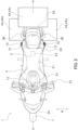
FIG. 2 is a top view of the straddled vehicle; -
FIG. 3 is a partially enlarged side view of a rear portion of the straddled vehicle; -
FIG. 4 is a partially enlarged side view of the rear portion of the straddled vehicle in a state where the storage case is removed from the straddled vehicle; -
FIG. 5 is a side view of a rear frame and a bracket; -
FIG. 6 is a top view of the rear frame and the bracket; -
FIG. 7 is a functional block diagram of a lock changing system; -
FIG. 8 is a flowchart of the lock changing system; and -
FIG. 9 is a flowchart of the lock changing system. - A straddled vehicle according to an embodiment will be described below with reference to drawings.
FIG. 1 is a side view of the straddledvehicle 1 according to the embodiment. - As shown in
FIG. 1 , the straddledvehicle 1 includes a vehicle frame 2 (an example of a vehicle body), asteering device 3, afuel tank 4, a rider seat 5 (an example of a seat), apower unit 6, afront wheel 7, aswing arm 8 and arear wheel 9. The straddledvehicle 1 includes atandem step 10 and akey cylinder 11. - In this embodiment, a front side of a rider (a front side in
FIG. 1 ), a rear side of the rider (a rear side inFIG. 1 ), a left side of the rider, and a right side of the rider respectively corresponds to each of front, rear, left and right directions of the straddledvehicle 1 in a state where the rider is seated on therider seat 5. - An upper side of the rider (an upper side in
FIG. 1 ) corresponds to an upper direction of the straddledvehicle 1. A downward direction of the straddled vehicle 1 (a downward side inFIG. 1 ) is a direction opposite to the upward direction of the straddledvehicle 1. The downward direction of the straddledvehicle 1 is a direction in which gravity acts on the straddledvehicle 1. - A vehicle front view indicates a state where a front portion of the straddled
vehicle 1 is viewed from the front side thereof. A vehicle side view indicates a state where a side surface of the straddledvehicle 1 is viewed from the left side thereof or the right side thereof. A vehicle rear view indicates a state where a rear portion of the straddledvehicle 1 is viewed from the rear side thereof. A vehicle upper view indicates a state where an upper portion of the straddledvehicle 1 is viewed from the upper side thereof. - As shown in
FIG. 2 , the straddledvehicle 1, for example, thevehicle frame 2, has a vehicle center plane H extending in a vehicle front-rear direction. The vehicle center plane H extends in the front-rear direction and a vehicle vertical direction. The vehicle center plane H passes through ahead pipe 12 in the front-rear direction. - For example, the vehicle center plane H passes through a center of the
head pipe 12 in the front-rear direction in the vehicle upper view. The vehicle center plane H forms a vehicle center line extending in the front-rear direction in the vehicle upper view. A vehicle width direction W is defined as a direction orthogonal to the vehicle center plane H. The vehicle width direction W corresponds to a vehicle left-right direction. - As shown in
FIG. 1 , thevehicle frame 2 includes ahead pipe 12, a main frame 13, and a rear frame 14. The main frame 13 is connected to thehead pipe 12. The main frame 13 includes a pair of main frames 20, 21. The pair of main frames 20, 21 extend rearward from thehead pipe 12 and are spaced apart from each other in the vehicle width direction W. -
FIG. 1 shows the left main frame 20. The right main frame 21 is disposed as a mirror image of the left main frame 20 with respect to the vehicle center plane H. A reference number 21 of the right main frame is indicated in a bracket with the reference number 20 of the left main frame. - As shown in
FIG. 1 , the rear frame 14 is connected to the main frame 13. The rear frame 14 includes a pair of rear frames 24, 25. The pair of rear frames 24, 25, for example, a left rear frame 24 and a right rear frame 25, respectively extend rearward from the pair of main frames 20, 21. -
FIG. 1 shows the left rear frame 24. The right rear frame 25 is disposed as a mirror image of the left rear frame 24 with respect to the vehicle center plane H. The right rear frame 25 is shown in brackets with the left rear frame 24. - As shown in
FIG. 1 , the left rear frame 24 and the right rear frame 25 are disposed at a lower side than therider seat 5. The pair of rear frames 24, 25 are respectively connected to the pair of main frames 20, 21. - The left rear frame 24 and the right rear frame 25 support the
rider seat 5. The left rear frame 24 includes a first leftrear frame 26 and a second leftrear frame 27. - As shown in
FIG. 1 , the first leftrear frame 26 supports therider seat 5. The first leftrear frame 26 is connected to the left main frame 20. The second leftrear frame 27 supports the first left rear frame 26 (seeFIG. 5 ). The second leftrear frame 27 is disposed at the lower side than the first leftrear frame 26. The second leftrear frame 27 is connected to the left main frame 20 and a rear portion of the first leftrear frame 26. - As shown in
FIG. 1 , thetandem step 10 is mounted to the second leftrear frame 27 via anarm portion 28. Thetandem step 10 is swingably mounted to thearm portion 28. For example, thetandem step 10 is swingably mounted to thearm portion 28 via a swing shaft 29 (an example of a mounting portion). - The right rear frame 25 is disposed as a mirror image of the left rear frame 24 with respect to the vehicle center plane H (see
FIG. 6 ). Except for this point, the configuration of the right rear frame 25 is the same as the configuration of the left rear frame 24. - As shown in
FIG. 1 , the right rear frame 25 includes a first rightrear frame 30 and a second rightrear frame 31. Thereference number 30 of the first right rear frame and thereference number 31 of the second right rear frame are respectively indicated in brackets with thereference number 26 of the first left rear frame and areference 27 number of the second left rear frame. - The first right
rear frame 30 is spaced apart from the first leftrear frame 26 in the vehicle width direction W (seeFIG. 6 ). The first rightrear frame 30 supports therider seat 5 with the first leftrear frame 26. The first rightrear frame 30 is connected to the right main frame 21. - The second right
rear frame 31 is spaced apart from the second leftrear frame 27 in the vehicle width direction W (seeFIG. 6 ). The second rightrear frame 31 supports the first right rear frame 30 (seeFIG. 5 ). The second rightrear frame 31 is disposed at the lower side than the first rightrear frame 30. The second rightrear frame 31 is connected to the right main frame 21 and a rear portion of the first rightrear frame 30. - As shown in
FIG. 1 , thesteering device 3 is rotatably supported on thehead pipe 12. Thesteering device 3 rotatably supports thefront wheel 7. Thesteering device 3 includes a steeringshaft 32, ahandle member 33, afront fork 34, anupper bracket 35 and alower bracket 36. - The steering
shaft 32 is inserted into thehead pipe 12. Thehandle member 33 is disposed at an upper side than thehead pipe 12. Thehandle member 33 is connected to the steeringshaft 32. Thehandle member 33 extends in the left-right direction. - The
front fork 34 is connected to steeringshaft 32 via theupper bracket 35 and thelower bracket 36. Thefront fork 34 rotatably supports thefront wheel 7. - As shown in
FIGS. 1 and2 , thefuel tank 4 is disposed at a rear side than thehead pipe 12. Thefuel tank 4 is disposed at a front side than therider seat 5. Thefuel tank 4 is disposed at the upper side than the main frame 13 and is supported by the main frame 13. - As shown in
FIGS. 1 and2 , therider seat 5 is provided on thevehicle frame 2. Therider seat 5 is supported by the rear frame 14. For example, therider seat 5 is supported by the first leftrear frame 26 and the first rightrear frame 30. - As shown in
FIG. 1 , therider seat 5 is disposed at the upper side than the rear frame 14. Therider seat 5 is disposed at the rear side than thefuel tank 4. Atandem seat 37 is disposed at the rear side than therider seat 5. Therider seat 5 is disposed between thefuel tank 4 and thetandem seat 37. - As shown in
FIG. 1 , thetandem seat 37 is supported by the rear frame 14. For example, thetandem seat 37 is supported by the first leftrear frame 26 and the first rightrear frame 30. - As shown in
FIGS. 1 and2 , agrab bar 38 is disposed around a rear portion of thetandem seat 37. Thegrab bar 38 surround the rear, left, and right portions oftandem seat 37. Thegrab bar 38 is supported by the rear frame 14. - As shown in
FIG. 1 , thekey cylinder 11 is configured to open and close therider seat 5. Thekey cylinder 11 is disposed at one side in the vehicle width direction W. In this embodiment, thekey cylinder 11 is disposed at the left side in the vehicle width direction W. Thekey cylinder 11 is disposed at the lower side than therider seat 5. Thekey cylinder 11 is disposed at the front side than aswitch 52 which is described later. - The
key cylinder 11 is mounted to thevehicle frame 2. For example, thekey cylinder 11 is mounted to a left rear cover 41 which is described later. The left rear cover 41 is mounted to the first leftrear frame 26 and the first rightrear frame 30. In other words, thekey cylinder 11 is mounted to the first leftrear frame 26 and the first rightrear frame 30 via the left rear cover 41. - As shown in
FIG. 1 , thepower unit 6 is disposed at the lower side than thefuel tank 4. Thepower unit 6 is supported by main frame 13. For example, thepower unit 6 includes an internal combustion engine. Therear wheel 9 is supported by main frame 13 via theswing arm 8. Therear wheel 9 is rotatably supported by theswing arm 8. Theswing arm 8 is swingably supported by the main frame 13. - The straddled
vehicle 1 includes amain cowl 22 and a rear cover 23. Themain cowl 22 is disposed at the front side than thehead pipe 12, at the left side than thehead pipe 12 and at the right side of thehead pipe 12. Themain cowl 22 is mounted to the main frame 13. - As shown in
FIG. 1 , themain cowl 22 is disposed at the front side than thehandle member 33, at the lateral side than a front portion of thefuel tank 4, at the lower side than thefuel tank 4 and at the lower side than therider seat 5. Themain cowl 22 covers an upper portion of the left main frame 20, an upper portion of the right main frame 21, a front portion of the left rear frame 24 and a front portion of the right rear frame 25. - As shown in
FIGS. 1 and3 , the rear cover 23 is disposed at the lower side than therider seat 5. For example, the rear cover 23 is disposed at the rear side than therider seat 5. The rear cover 23 is disposed at the lower side than therider seat 5 and at the lower side than thetandem seat 37. The rear cover 23 includes a pair of rear covers 41, 42, for example, the left rear cover 41 and a right rear cover 42. - The right rear cover 42 is disposed as a mirror image of the left rear cover 41 with respect to the vehicle center plane H. The reference number 42 of the right rear cover is indicated in brackets with the reference number 41 of the left rear cover.
- As shown in
FIGS. 1 and3 , the left rear cover 41 covers middle and rear portions of the left rear frame 24, for example, the middle and rear portions of the first leftrear frame 26 and the second leftrear frame 27. The left rear cover 41 is mounted to the first leftrear frame 26. As shown inFIG. 4 , the left rear cover 41 includes a first sidecase mounting hole 41a and aswitch mounting surface 41b. - As shown in
FIG. 4 , the first sidecase mounting hole 41a is a hole which is used to mount a left-side case 44a, which is described later, to the first leftrear frame 26. Theswitch 52, for example, aswitch holder 43 which is described later, is provided on theswitch mounting surface 41b. Theswitch mounting surface 41b forms an outer surface of the left rear cover 41 so as to incline inward in the vehicle width direction W as theswitch mounting surface 41b goes toward the lower side. - As shown in
FIGS. 1 and3 , the right rear cover 42 covers middle and rear portions of the right rear frame 25, for example, the middle and rear portions of the first rightrear frame 30 and the second rightrear frame 31. The right rear cover 42 is mounted to the first rightrear frame 30. As shown inFIG. 4 , the right rear cover 42 includes a second sidecase mounting hole 42a. The second sidecase mounting hole 42a is a hole which is used to mount a right-side case 44b, which will be described late, to the first rightrear frame 30. - As shown in
FIG. 4 , the straddledvehicle 1 includes theswitch holder 43. Theswitch holder 43 is configured to hold theswitch 52. Theswitch holder 43 is a hole which holds theswitch 52. - The
switch holder 43 is disposed at one side in the vehicle width direction W. In this embodiment, theswitch holder 43 is disposed at the left side in the vehicle width direction W. Theswitch holder 43 is disposed at the upper side than the second leftrear frame 27. Theswitch holder 43 is disposed at the lower side than the first leftrear frame 26. - The
switch holder 43 is disposed at the rear side than areceiver 51 and at the front side than abracket 45. Thereceiver 51 and thebracket 45 are described later. For example, theswitch holder 43 is disposed at the rear side than thereceiver 51 in the vehicle side view and at the front side than a first side bracket 47 which is described later in the vehicle side view. Theswitch holder 43 is disposed at the rear side than thereceiver 51 in the vehicle side view and at the front side than asecond side bracket 48 which is described later in the vehicle side view. - The
switch holder 43 is provided on a side surface of the left rear cover 41 or an upper surface of the left rear cover 41. In this embodiment, theswitch holder 43 is provided on the side surface of the left rear cover 41. An example in which theswitch holder 43 is provided on the upper surface of the left rear cover 41 is indicated by a dashed line using the reference number "43'" inFIG. 4 . - The left rear cover 41 is mounted to the first left
rear frame 26. Theswitch holder 43 is provided on theswitch mounting surface 41b of the left rear cover 41. In other words, theswitch holder 43 is mounted to the first leftrear frame 26 via the left rear cover 41. - As shown in
FIGS. 1 to 3 , the straddledvehicle 1 is configured to mount a storage case 44. The straddledvehicle 1 includes the storage case 44 shown inFIGS. 1-3 and thebracket 45 shown inFIGS. 4-6 . In this embodiment, an example in which the storage case 44 is a component of the straddledvehicle 1 is described, but the storage case 44 may not be the component of the straddledvehicle 1. - The storage case 44 is configured to accommodate articles. The storage case 44 is configured to open and close for accommodating the articles and taking out the articles. The storage case 44 includes a
locking mechanism 44e shown inFIG. 7 . Thelocking mechanism 44e is configured to change the locking state. The locking state includes an unlocked state which permits opening and closing of the storage case 44 and a locked state which restricts opening and closing of the storage case 44. - The storage case 44 shown in
FIGS. 1-3 is detachably mounted to thevehicle frame 2 via thebracket 45 shown inFIGS. 4-6 . As shown inFIGS. 1 to 3 , the storage case 44 includes the left-side case 44a, the right-side case 44b, and a top case 44c. - The left-
side case 44a is disposed at the left side than thevehicle frame 2 at the rear portion of thevehicle frame 2. The left-side case 44a is disposed at the left side than the first leftrear frame 26. The right-side case 44b is disposed at the right side than thevehicle frame 2 at the rear portion of thevehicle frame 2. The right-side case 44b is disposed at the right side than the first rightrear frame 30. - The top case 44c is disposed at the rear side than the
rider seat 5. For example, the top case 44c is disposed at the rear side than thetandem seat 37. The top case 44c is disposed at the upper side than thevehicle frame 2 at the rear portion of thevehicle frame 2. Specifically, the top case 44c is disposed at the upper side than the rear end of the first leftrear frame 26 and the rear end of the first rightrear frame 30. - The
bracket 45 shown inFIGS. 4 to 6 is used to mount the storage case 44 to thevehicle frame 2. As shown inFIGS. 5 and6 , thebracket 45 is provided on thevehicle frame 2, for example, the first leftrear frame 26 and the first rightrear frame 30. Thebracket 45 includes the first side bracket 47 and thesecond side bracket 48. Thebracket 45 includes a first rear bracket 49 and a second rear bracket 50. - The first side bracket 47 shown in
FIGS. 5 and6 is used to mount the left-side case 44a. As shown inFIG. 4 , the first side bracket 47 is disposed at the rear side than therider seat 5. The first side bracket 47 is disposed at the lower side than thetandem seat 37. - As shown in
FIGS. 5 and6 , the first side bracket 47 is mounted to the rear portion of the first leftrear frame 26. For example, the left-side case 44a is detachably mounted to the first side bracket 47 via the first sidecase mounting hole 41a shown inFIG. 4 . - The
second side bracket 48 shown inFIGS. 5 and6 is used to mount the right-side case 44b. As shown inFIG. 4 , thesecond side bracket 48 is disposed at the rear side than therider seat 5. Thesecond side bracket 48 is disposed at the lower side than thetandem seat 37. - As shown in
FIGS. 5 and6 , thesecond side bracket 48 is mounted to the rear portion of the first rightrear frame 30. For example, the right-side case 44b is detachably mounted to thesecond side bracket 48 via the second sidecase mounting hole 42a shown inFIG. 4 . - The first rear bracket 49 and the second rear bracket 50 shown in
FIGS. 5 and6 are used to mount the top case 44c. The first rear bracket 49 is mounted to the rear end of the first leftrear frame 26. The second rear bracket 50 is mounted to the rear end of the first rightrear frame 30. The top case 44c is detachably mounted to the first rear bracket 49 and the second rear bracket 50 via a stay or stays (not shown). - As shown in
FIG. 1 , the straddledvehicle 1 includes thereceiver 51, theswitch 52 and abattery 53. The straddledvehicle 1 includes a firstvehicle speed sensor 54, a secondvehicle speed sensor 55 and acontroller 61. - The
receiver 51 is disposed at one side in the vehicle width direction W. In this embodiment, thereceiver 51 is disposed at the left side in the vehicle width direction W. Thereceiver 51 is mounted to thevehicle frame 2, for example, the first leftrear frame 26 and/or the first rightrear frame 30. - As shown in
FIG. 4 , thereceiver 51 is disposed at the lower side than therider seat 5. Thereceiver 51 is disposed at the lower side than the first leftrear frame 26. Thereceiver 51 is disposed at the upper side than second leftrear frame 27. In other words, thereceiver 51 is disposed between the first leftrear frame 26 and the second leftrear frame 27 in the vertical direction. - As shown in
FIG. 7 , thereceiver 51 is configured to receive an identification signal from a portable transmitter M. Thereceiver 51 receives the identification signal, which is used to identify the portable transmitter M, from the portable transmitter M. For example, thereceiver 51 receives the identification signal from the portable transmitter M according to distance from the portable transmitter M. - Specifically, the
receiver 51 receives the identification signal from the portable transmitter M, when the distance between the portable transmitter M and thereceiver 51 is smaller than or equal to a predetermined distance. In this case, thereceiver 51 transmits the identification signal tocontroller 61. Thereceiver 51 does not receive the identification signal from the portable transmitter M, when the distance between the portable transmitter M and thereceiver 51 is larger than the predetermined distance. In this case, thereceiver 51 does not transmit the identification signal tocontroller 61. - The
switch 52 shown inFIGS. 1 and4 is disposed at one side in the vehicle width direction W. In this embodiment, theswitch 52 is disposed at the left side in the vehicle width direction W. As shown inFIG. 4 , theswitch 52 is disposed at the rear side than thereceiver 51 and at the front side than thebracket 45. For example, theswitch 52 is disposed at the rear side than thereceiver 51 and at the front side than the first side bracket 47 in the vehicle side view. Theswitch 52 is disposed at the rear side than thereceiver 51 and at the front side than thesecond side bracket 48 in the vehicle side view. - As shown in
FIG. 1 , theswitch 52 is spaced apart from the storage case 44 so as not to overlap the storage case 44 in the vehicle side view. For example, theswitch 52 is spaced apart from the left-side case 44a so as not to overlap the left-side case 44a in the vehicle side view. Specifically, theswitch 52 is spaced apart from the left-side case 44a and the right-side case 44b so as not to overlap the left-side case 44a and the right-side case 44b in the vehicle side view. - As shown in
FIG. 4 , at least a portion of theswitch 52 is disposed at the upper side than the second leftrear frame 27. In this embodiment, an example in which theswitch 52 is disposed at the upper side than the second leftrear frame 27 is described, but a portion of theswitch 52 can be disposed at the lateral side than the second leftrear frame 27. Theswitch 52 is disposed at the rear side than theswing shaft 29 of thetandem step 10. - The
switch 52 is mounted to the side surface of the left rear cover 41 or the upper surface of the left rear cover 41. In this embodiment, theswitch 52 is mounted to the side surface of the left rear cover 41. An example in which theswitch 52 is provided on the upper surface of the left rear cover 41 is indicated by a dashed line using the reference number "52'" inFIG. 4 . - The
switch 52 is mounted to the switch holder 43 (the hole) of the left rear cover 41. For example, theswitch 52 is elastically engaged with the switch holder 43 (the hole). The left rear cover 41 is mounted to the first leftrear frame 26. In other words, theswitch 52 is mounted to the first leftrear frame 26 via the left rear cover 41. - The
switch 52 is operated to change the locking state of the storage case 44. Theswitch 52 is operated to change the locking state of the left-side case 44a and the right-side case 44b from at least the locking state to the unlocking state. - When the
receiver 51 receives the identification signal from the portable transmitter M, theswitch 52 changes the locking state of the left-side case 44a and the right-side case 44b from one of the locked state and the unlocked state to the other of the locked state and the unlocked state. - For example, as shown in
FIG. 7 , theswitch 52 includes alock button 52a which is used to lock the storage case 44 and anunlock button 52b which is used to unlock the storage case 44. Theswitch 52 transmits a lock signal to thecontroller 61 when thelock button 52a is pressed. Theswitch 52 transmits an unlock signal to thecontroller 61 when theunlock button 52b is pressed. - The
battery 53 shown inFIGS. 1 and4 supplies power to thereceiver 51, the firstvehicle speed sensor 54, the secondvehicle speed sensor 55 and thecontroller 61. Each of theswitch 52 and the storage case 44 contain a battery for operating theswitch 52 and asignal receiving unit 44d which is described later. - As shown in
FIG. 4 , thebattery 53 is disposed at the lower side than therider seat 5. Thebattery 53 is disposed between therider seat 5 and thereceiver 51 in the vertical direction. For example, thebattery 53 is disposed between therider seat 5 and the second leftrear frame 27 in the vertical direction. Thebattery 53 is mounted to the first leftrear frame 26. - As shown in
FIG. 1 , the firstvehicle speed sensor 54 is mounted to a tip portion of the leftfront fork 34 which is included in thefront fork 34. The firstvehicle speed sensor 54 detects a rotational speed of thefront wheel 7. The firstvehicle speed sensor 54 transmits a first rotational speed signal corresponding to the rotational speed of thefront wheel 7 to thecontroller 61. - The second
vehicle speed sensor 55 is mounted to a tip portion of theleft swing arm 8 which is included in theswing arm 8. The secondvehicle speed sensor 55 detects a rotational speed of therear wheel 9. The secondvehicle speed sensor 55 transmits a second rotational speed signal corresponding to the rotation speed of therear wheel 9 to thecontroller 61. - As shown in
FIG. 7 , thecontroller 61 includes aprocessor 61a and amemory 61b. Thecontroller 61 can further include an external storage device and an auxiliary storage device such as a hard disk and/or SSD (Solid State Drive). - The
processor 61a includes at least one CPU (Central Processing Unit). In this embodiment, an example in which theprocessor 61a includes one CPU is described. In this embodiment, an example in which theprocessor 61a includes one CPU is described, but theprocessor 61a includes a plurality of CPUs. - The
processor 61a controls a lock changing system, which will be described later, based on control program recorded in thememory 61b. When control of the lock changing system is executed, theprocessor 61a reads control data from thememory 61b and records the control data in thememory 61b. - The
memory 61b includes a volatile memory such as RAM (Random Access Memory). Thememory 61b includes a non-volatile memory such as ROM (Read Only Memory). Thememory 61b records the control program and the control data which is used in executing the lock changing system. - The
controller 61 shown inFIG. 1 is mounted to the main frame 13. Thecontroller 61 is disposed at the front side than thefuel tank 4. In this embodiment, the portable transmitter M, theswitch 52, thereceiver 51, thesignal receiving unit 44d of the storage case 44 which will be described later and thecontroller 61 are connected to each other by wireless communication. Thecontroller 61, thebattery 53, the firstvehicle speed sensor 54 and the secondvehicle speed sensor 55 are connected to each other by wire communication. Thecontroller 61, thebattery 53, the firstvehicle speed sensor 54 and the secondvehicle speed sensor 55 can be connected to each other by the wireless communication. - In this embodiment, as shown in
FIG. 7 , each of the left-side case 44a and the right-side case 44b includes thesignal receiving unit 44d. In this embodiment, an example in which the top case 44c does not have thesignal receiving unit 44d is described, but the top case 44c can have thesignal receiving unit 44d. - The
signal receiving unit 44d is supplied with power from the battery which is provided on each of the left-side case 44a, the right-side case 44b and the top case 44c. Thesignal receiving unit 44d receives the command signal for changing the locking state from thecontroller 61. The command signal includes the lock signal and the unlock signal. - In the lock changing system, the
processor 61a operates as follows. Theprocessor 61a shown inFIG. 7 detects the portable transmitter M. For example, theprocessor 61a detects the identification signal from the portable transmitter M. Specifically, theprocessor 61a detects the identification signal from portable transmitter M via thereceiver 51. Theprocessor 61a receives the identification signal from thereceiver 51 when the distance between the portable transmitter M and thereceiver 51 is smaller than or equal to the predetermined distance. - The
processor 61a authenticates the portable transmitter M with the identification signal. For example, when theprocessor 61a receives the identification signal from thereceiver 51, theprocessor 61a compares a first identification information of the portable transmitter M corresponding to the identification signal with a second identification information of the portable transmitter M recorded in thememory 61b. Theprocessor 61a recognizes the portable transmitter M when the first identification information and the second identification information match. Theprocessor 61a does not receive the identification signal from the portable transmitter M when the distance between the portable transmitter M and thereceiver 51 is larger than the predetermined distance. Theprocessor 61a does not recognize the portable transmitter M when theprocessor 61a does not receive the identification signal from thereceiver 51. - The
processor 61a controls thelocking mechanism 44e of the storage case 44 (the left-side case 44a and the right-side case 44b). When theswitch 52 is operated in a state where theprocessor 61a recognizes the portable transmitter M, theprocessor 61a receives the lock signal or the unlock signal from theswitch 52 and transmits the command signal (the lock signal or the unlock signal) to thesignal receiving unit 44d of the storage case 44. Thereby, thelocking mechanism 44e of the storage case 44 is locked or unlocked. - When the
switch 52 is operated in a state where theprocessor 61a does not recognize the portable transmitter M, theprocessor 61a receives the lock signal or the unlock signal from theswitch 52 and does not transmit the command signal (the lock signal or the unlock signal) to thesignal receiving unit 44d of the storage case 44. In this case, the locking state of thelocking mechanism 44e of the storage case 44 is maintained. - The
processor 61a receives the first rotational speed signal and the second rotational speed signal from each of the firstvehicle speed sensor 54 and the secondvehicle speed sensor 55. In case that the rotation speed of thefront wheel 7 corresponding to the first rotational speed signal and the rotation speed of therear wheel 9 corresponding to the second rotational speed signal are smaller than or equal to a predetermined value, theprocessor 61a transmits the command signal (the lock signal or the unlock signal) to thesignal receiving unit 44d of the storage case 44 when theprocessor 61a receives the lock signal or the unlock signal from theswitch 52. Thereby, thelocking mechanism 44e of the storage case 44 is activated when theswitch 52 is pressed. A range is which "the rotation speed is smaller than or equal to the predetermined value" is set to a range in which the straddledvehicle 1 is determined to be stationary. - When the rotational speed of the
front wheel 7 corresponding to the first rotational speed signal and the rotational speed of therear wheel 9 corresponding to the second rotational speed signal are larger than the predetermined value, theprocessor 61a does not transmit the command signal (the lock signal or the unlock signal) to thesignal receiving unit 44d of the storage case 44 when theprocessor 61a receives the lock signal or the unlock signal from theswitch 52. Thereby, even if theswitch 52 is pressed during driving, the operation of thelocking mechanism 44e of the storage case 44 is restricted. A range in which "the rotation speed is larger than the predetermined value" is set to a range in which the straddledvehicle 1 is determined to move. - The lock changing system having the above functions is realized by the
processor 61a as follows.FIGS. 8 and9 are flowcharts of the lock changing system. - The
processor 61a monitors the first rotational speed signal of the firstvehicle speed sensor 54 and the second rotational speed signal of the second vehicle speed sensor 55 (S1). Theprocessor 61a determines whether the straddledvehicle 1 is stationary based on the rotational speed of thefront wheel 7 corresponding to the first rotational speed signal and the rotational speed of therear wheel 9 corresponding to the second rotational speed signal (S2). - When the straddled
vehicle 1 is not stationary (No in S2), for example, when the straddledvehicle 1 is moving (No in S2), the operation of thelocking mechanism 44e of the storage case 44 is restricted even if theswitch 52 is pressed during driving. When the straddledvehicle 1 is stationary (Yes in S2), theprocessor 61a performs processing of a step 3 (S3) at the lower side than. - The
processor 61a monitors the identification signal (S3). Theprocessor 61a determines whether the identification signal has been received from the receiver 51 (S4). When theprocessor 61a does not receive the identification signal from the receiver 51 (No in S4), for example, when the portable transmitter M is away from thereceiver 51, theprocessor 61a performs the processing of the step 1 (S1). - When the
processor 61a receives the identification signal from the receiver 51 (Yes in S4), for example, when the portable transmitter M approaches thereceiver 51, theprocessor 61a determines whether the first identification information of the portable transmitter M matches with the second identification information recorded in thememory 61b (S5). When the first identification information and the second identification information do not match (No in S5), theprocessor 61a performs the processing of the step 1 (S1). In this case, theprocessor 61a does not authenticate the portable transmitter M and does not transmit the command signal (the lock signal or the unlock signal) to thesignal receiving unit 44d of the storage case 44 even if theswitch 52 is operated. - When the first identification information and the second identification information match (Yes in S5), the
processor 61a recognizes the portable transmitter M (S6). Theprocessor 61a determines whether theswitch 52 has been operated (S7). When theswitch 52 is operated (Yes in S7), theprocessor 61a transmits the command signal (the lock signal or the unlock signal) to thesignal receiving unit 44d of the storage case 44 (S8). - Thereby, the
locking mechanism 44e of the storage case 44 is locked or unlocked. For example, when theunlock button 52b of theswitch 52 is pressed, the storage case 44 is unlocked. When thelock button 52a of theswitch 52 is pressed, the storage case 44 is locked. - When the
switch 52 is not operated (No in S7), theprocessor 61a does not transmit the command signal (the lock signal or the unlock signal) to thesignal receiving unit 44d of the storage case 44 (S9). - The
processor 61a always monitors the processing of the step 3 (S3) while the processing of the steps 7-9 (S7-S9) is performed. The processing of the steps 7-9 (S7-S9) are performed while theprocessor 61a receives the identification signal from thereceiver 51 in step 4 (S4). On the other hand, when theprocessor 61a no longer receives the identification signal from thereceiver 51 in step 4 (S4), the processing of the steps 7-9 (S7-S9) ends and the processing of the step 1 (S1) is performed. - The straddled
vehicle 1 described above has the following features. With the straddledvehicle 1, thereceiver 51 can easily recognize the portable transmitter M even if the portable transmitter M is positioned at the front side than the straddledvehicle 1 or at the rear side than the straddledvehicle 1, since thereceiver 51 is mounted to thevehicle frame 2 at the lower side than therider seat 5. - In addition, the
receiver 51 can easily recognize the portable transmitter M even if the rider approaches theswitch 52 to operate theswitch 52, since theswitch 52 is mounted to thevehicle frame 2 at the rear side than thereceiver 51 and at the front side than the bracket 45 (the first side bracket 47 and the second side bracket 48). - Furthermore, the rider can easily access the storage case 44 (the left-
side case 44a and the right-side case 44b) after the rider operates theswitch 52. In other words, the straddledvehicle 1, which can easily recognize the portable transmitter M positioned around the straddledvehicle 1 and can improve accessibility to the storage case 44, is provided. - The
receiver 51 can easily recognize the portable transmitter M when the rider approaches theswitch 52, since theswitch 52 is mounted to thevehicle frame 2 at one side in the vehicle width direction W orthogonal to the vehicle center plane H. The receiver can more easily recognize the portable transmitter M when the rider approaches theswitch 52, since thereceiver 51 is mounted to thevehicle frame 2 at the same side as theswitch 52. - The rider can easily open and close the
rider seat 5 after the rider access the storage case 44 (the left-side case 44a and the right-side case 44b), since thekey cylinder 11 is mounted to thevehicle frame 2 at the same side as theswitch 52. In addition, the rider can easily access the storage case 44 after the rider opens and closes therider seat 5. - The rear cover 23 (the left rear cover 41) is mounted to the
vehicle frame 2 at the rear side than therider seat 5. Theswitch 52 is mounted to the side surface of the rear cover 23 (the left rear cover 41). Thereby, the rider can easily access theswitch 52. - The
switch 52 can be mounted to the upper surface of the rear cover 23 (the left rear cover 41). Even if the straddledvehicle 1 is configured in this way, the rider can easily access theswitch 52. - The
receiver 51 can easily recognize the portable transmitter M, since thereceiver 51 is disposed at the upper side than the second leftrear frame 27 and at the lower side than the first leftrear frame 26. - It is possible to prevent a passenger from contacting the
switch 52 in a state where the rider and the passenger ride on the straddledvehicle 1, since theswitch 52 is disposed at the rear side than theswing shaft 29 of thetandem step 10. - The
switch 52 is disposed at the upper side than the second leftrear frame 27. In this configuration, the rider can easily operate the switch, since the at least a portion of theswitch 52 is disposed at the upper side than the second leftrear frame 27. - The rider can easily access the storage case 44 after the rider operates the
switch 52, since the storage case 44 (the left-side case 44a and the right-side case 44b) is mounted to the bracket 45 (the first side bracket 47 and the second side bracket 48) including the above layout. - The straddled
vehicle 1 can improve accessibility to the storage case 44 without reducing usability of theswitch 52, since theswitch 52 can be spaced apart from the storage case 44 so as not to overlap the storage case 44 (the left-side case 44a and the right-side case 44b) in the vehicle side view. - With the straddled
vehicle 1, thecontroller 61 authenticates the portable transmitter M based on the identification signal from the portable transmitter M and the locking state of the storage case 44 (the left-side case 44a and the right-side case 44b) is changed based on the command signal (the lock signal or the unlock signal) from thecontroller 61 when theswitch 52 is operated. - Thus, the locking state of the storage case 44 can be easily changed by the
controller 61. For example, the locking state of the storage case 44 can be easily changed from one of the locked state and the unlocked state to the other of the locked state and the unlocked state by operation of theswitch 52. - It is possible to prevent the passenger from contacting the
switch 52 in a state where the rider and the passenger ride on the straddledvehicle 1, since theswitch mounting surface 41b incline inward in the vehicle width direction W as theswitch mounting surface 41b goes toward the lower side. - The
switch holder 43 is mounted to thevehicle frame 2 at the rear side than thereceiver 51 and at the front side than the bracket 45 (the first side bracket 47 and the second side bracket 48). Thereby, thereceiver 51 can easily recognize the portable transmitter M even if the rider approaches theswitch 52 to operate theswitch 52. - In addition, the rider can easily access the storage case 44 (the left-
side case 44a and the right-side case 44b) after the rider operates theswitch 52. In other words, the straddledvehicle 1, which can easily recognize the portable transmitter M positioned around the straddledvehicle 1 and can improve accessibility to the storage case 44, is provided. - According to the present teaching, a straddled vehicle, which can easily recognize a portable transmitter positioned around the straddled vehicle and can improve accessibility to a storage case, is provided.
-
- 1
- straddled vehicle
- 2
- vehicle frame
- 5
- rider seat
- 10
- tandem step
- 11
- key cylinder
- 24
- rear cover
- 26
- first left rear frame
- 27
- second left rear frame
- 41
- left rear cover
- 41b
- switch mounting surface
- 43
- switch holder
- 44d
- signal receiving unit
- 44
- storage case
- 44a
- left-side case
- 44b
- right-side case
- 45
- bracket
- 47
- first side bracket
- 48
- second side bracket
- 51
- receiver
- 52
- switch
- 61
- controller
- H
- vehicle center plane
- M
- portable transmitter
- W
- vehicle width direction
Claims (16)
- A straddled vehicle (1) configured to mount a storage case (44) and configured to change a locking state of the storage case (44) according to an identification signal, the straddled vehicle (1) comprises:a vehicle body (2);a seat (5) provided on the vehicle body (2);a bracket (45) disposed at a rear side than the seat (5) in a vehicle front-rear direction and provided on the vehicle body (2), the bracket (45) is configured to mount the storage case (44) to the vehicle body (2);a receiver (11) mounted to the vehicle body (2) at a lower side than the seat (5) in a vehicle vertical direction and configured to receive the identification signal; anda switch (52) mounted to the vehicle body (2) at the rear side than the receiver (11) and at a front side than the bracket (45) in the vehicle front-rear direction, the switch (52) configured to be operated to change the locking state of the storage case (44).
- The straddled vehicle (1) according to claim 1, wherein the vehicle body (2) includesa vehicle center line extending in the vehicle front-rear direction; andthe switch (52) is mounted to the vehicle body (2) at one side in a vehicle width direction (W) orthogonal to the vehicle center line.
- The straddled vehicle (1) according to claim 2, wherein the receiver (11) is mounted to the vehicle body (2) at the one side in a vehicle width direction (W).
- The straddled vehicle (1) according to claim 2 or 3, further comprising:
a key cylinder (11) configured to open and close the seat (5) and mounted to the vehicle body (2) at the one side in the vehicle width direction (W). - The straddled vehicle (1) according to at least one of the claims 1 to 4, further comprising:a rear cover (41) mounted to the vehicle body (2) at the rear side than the seat (5) in the vehicle front-rear direction; whereinthe switch (52) is mounted to a side surface of the rear cover (41).
- The straddled vehicle (1) according to at least one of the claims 1 to 4, further comprising:a rear cover (41) mounted to the vehicle body (2) at the rear side than the seat (5) in the vehicle front-rear direction; whereinthe switch (52) is mounted to an upper surface of the rear cover (41) in the vehicle vertical direction.
- The straddled vehicle (1) according to at least one of the claims 1 to 6, wherein the vehicle body (2) includes a first rear frame (26, 30) and a second rear frame (27, 31); the first rear frame supports (26, 30) the seat (5) and a second rear frame (27,31); the second rear frame (27, 31) is disposed at the lower side than the first rear frame (26, 30) ) in the vehicle vertical direction and is connected to a rear portion of the first rear frame (26, 30) in the vehicle front-rear direction; andthe receiver (11) is disposed at an upper side than the second rear frame (27, 31) in the vehicle vertical direction, and/orat least a portion of the switch (52) is disposed at the upper side than the second rear frame (27, 31) in the vehicle vertical direction.
- The straddled vehicle (1) according to claim 7, wherein the receiver (11) is disposed at the lower side than the first rear frame (26, 30) in the vehicle vertical direction.
- The straddled vehicle (1) according to at least one of the claims 1 to 8, further comprising:a tandem step (10) including a mounting portion (29) mounted to the vehicle body (2); whereinthe switch (52) is disposed at the rear side than the mounting portion (29) of the tandem step (10) in the vehicle front-rear direction.
- The straddled vehicle (1) according to at least one of the claims 1 to 9, wherein, with the storage case (44) mounted to the bracket (45), the switch (52) is spaced apart from the storage case (44) so as not to be overlapped by the storage case (44) in a vehicle side view.
- The straddled vehicle (1) according to at least one of the claims 1 to 10, wherein the switch (52) is configured to be operated to change the locking state of the storage case (44) at least from a locked state to an unlocked state.
- The straddled vehicle (1) according to at least one of the claims 1 to 11, wherein the vehicle body (2) has a mounting surface (41b) on which the switch (52) is mounted; and
the mounting surface (41b) inclines inward in a vehicle width direction (W) orthogonal to the vehicle front-rear direction as the mounting surface (41b) goes toward a lower side in the vehicle vertical direction. - The straddled vehicle (1) according to at least one of the claims 1 to 12, further comprising:
a switch holder (43) mounted to the vehicle body (2) at the rear side than the receiver (11) and at a front side than the bracket (45) in the vehicle front-rear direction, the switch holder (43) is configured to hold the switch (52) operated to change the locking state of the storage case (44). - The straddled vehicle (1) according to at least one of the claims 1 to 13, further comprising:
a portable transmitter (M) configured to transmit the identification signal to authenticate the portable transmitter (M), wherein the receiver (11) is configured to receive the identification signal from the portable transmitter (M). - The straddled vehicle (1) according to claim 14, further comprising:a controller (61) configured to authenticate the portable transmitter (M) based on the identification signal; whereinthe storage case (44) includes a signal receiving unit (44d) configured to receive a command signal for changing the locking state from the controller (61); andthe controller (61) is configured to transmit the command signal to the signal receiving unit (44d) when the switch (52) is operated in a state where the portable transmitter (M) is authenticated.
- A straddled vehicle (1) configured to mount a storage case (44) and to change a locking state of the storage case (44) by detecting an identification signal from a portable transmitter (M):a vehicle body (2);a seat (5) provided on the vehicle body (2);a bracket (45) disposed at a rear side than the seat (5) in a vehicle front-rear direction and provided on the vehicle body (2), the bracket (45) is configured to mount the storage case (44) to the vehicle body (2);a receiver (11) mounted to the vehicle body (2) at a lower side than the seat in a vehicle vertical direction and configured to receive the identification signal from the portable transmitter (M); anda switch holder (43) mounted to the vehicle body (2) at the rear side than the receiver and at a front side than the bracket in a vehicle front-rear direction.
Applications Claiming Priority (1)
| Application Number | Priority Date | Filing Date | Title |
|---|---|---|---|
| JP2023009027A JP2024104682A (en) | 2023-01-24 | 2023-01-24 | Saddle-type vehicle |
Publications (2)
| Publication Number | Publication Date |
|---|---|
| EP4406818A1 true EP4406818A1 (en) | 2024-07-31 |
| EP4406818B1 EP4406818B1 (en) | 2026-01-28 |
Family
ID=88921085
Family Applications (1)
| Application Number | Title | Priority Date | Filing Date |
|---|---|---|---|
| EP23211117.9A Active EP4406818B1 (en) | 2023-01-24 | 2023-11-21 | Straddled vehicle |
Country Status (3)
| Country | Link |
|---|---|
| EP (1) | EP4406818B1 (en) |
| JP (1) | JP2024104682A (en) |
| CN (1) | CN118397734A (en) |
Citations (5)
| Publication number | Priority date | Publication date | Assignee | Title |
|---|---|---|---|---|
| EP3018043B1 (en) * | 2014-09-30 | 2017-06-21 | Honda Motor Co., Ltd. | Saddle-type vehicle and additional storage box for use on saddle-type vehicle |
| WO2019003700A1 (en) * | 2017-06-29 | 2019-01-03 | 本田技研工業株式会社 | Motorcycle |
| EP3265370B1 (en) * | 2015-03-02 | 2019-10-23 | Bayerische Motoren Werke Aktiengesellschaft | Assembly having a storage compartment on a motorized two-wheeled vehicle |
| WO2020174544A1 (en) | 2019-02-25 | 2020-09-03 | 本田技研工業株式会社 | Vehicle, vehicle onboard device, and management method |
| EP3747748A1 (en) * | 2018-01-31 | 2020-12-09 | Honda Motor Co., Ltd. | Saddle riding type vehicle |
Family Cites Families (1)
| Publication number | Priority date | Publication date | Assignee | Title |
|---|---|---|---|---|
| JP2017019361A (en) * | 2015-07-09 | 2017-01-26 | ヤマハ発動機株式会社 | Saddle-riding type vehicle authentication system and saddle-riding type vehicle |
-
2023
- 2023-01-24 JP JP2023009027A patent/JP2024104682A/en active Pending
- 2023-11-21 EP EP23211117.9A patent/EP4406818B1/en active Active
-
2024
- 2024-01-23 CN CN202410091858.7A patent/CN118397734A/en active Pending
Patent Citations (5)
| Publication number | Priority date | Publication date | Assignee | Title |
|---|---|---|---|---|
| EP3018043B1 (en) * | 2014-09-30 | 2017-06-21 | Honda Motor Co., Ltd. | Saddle-type vehicle and additional storage box for use on saddle-type vehicle |
| EP3265370B1 (en) * | 2015-03-02 | 2019-10-23 | Bayerische Motoren Werke Aktiengesellschaft | Assembly having a storage compartment on a motorized two-wheeled vehicle |
| WO2019003700A1 (en) * | 2017-06-29 | 2019-01-03 | 本田技研工業株式会社 | Motorcycle |
| EP3747748A1 (en) * | 2018-01-31 | 2020-12-09 | Honda Motor Co., Ltd. | Saddle riding type vehicle |
| WO2020174544A1 (en) | 2019-02-25 | 2020-09-03 | 本田技研工業株式会社 | Vehicle, vehicle onboard device, and management method |
Also Published As
| Publication number | Publication date |
|---|---|
| CN118397734A (en) | 2024-07-26 |
| JP2024104682A (en) | 2024-08-05 |
| EP4406818B1 (en) | 2026-01-28 |
Similar Documents
| Publication | Publication Date | Title |
|---|---|---|
| JP6561970B2 (en) | vehicle | |
| JP3844231B2 (en) | Motorcycle anti-theft device | |
| EP2021214B1 (en) | Motorcycle handlebar lock system | |
| CA2674198C (en) | Vehicle storage box locking device | |
| US7196612B2 (en) | Saddle type vehicle having a remote control type trunk | |
| US6428076B2 (en) | Remote control type vehicular trunk | |
| EP3617050B1 (en) | Straddled vehicle | |
| EP2045151B1 (en) | Immobilizer device | |
| EP1724167B1 (en) | Vehicle controller for straddle-type vehicle | |
| JP2006321454A (en) | Vehicle control device for saddle riding type vehicle | |
| JP5204427B2 (en) | Event data recorder | |
| EP4406818B1 (en) | Straddled vehicle | |
| EP1232919B1 (en) | Remote lock operation apparatus for light vehicle | |
| JP2008179274A (en) | Vehicle antitheft device | |
| JP2018188082A (en) | Vehicle seat position control device | |
| US20220177063A1 (en) | Straddled vehicle | |
| US9656718B2 (en) | Saddle riding type vehicle | |
| EP3106377B1 (en) | Lid supporting structure | |
| JPH11227658A (en) | Fuel lid device for scooter type vehicle | |
| EP3929015B1 (en) | Straddled vehicle cap for fuel tank | |
| CN113942600B (en) | Steering lock system for vehicle | |
| JP7626865B2 (en) | Tank cap | |
| JP2009061957A (en) | Immobilizer | |
| JP7739373B2 (en) | Starting control device, starting control unit, and saddle-type vehicle | |
| JP7507310B2 (en) | vehicle |
Legal Events
| Date | Code | Title | Description |
|---|---|---|---|
| PUAI | Public reference made under article 153(3) epc to a published international application that has entered the european phase |
Free format text: ORIGINAL CODE: 0009012 |
|
| STAA | Information on the status of an ep patent application or granted ep patent |
Free format text: STATUS: REQUEST FOR EXAMINATION WAS MADE |
|
| 17P | Request for examination filed |
Effective date: 20231121 |
|
| AK | Designated contracting states |
Kind code of ref document: A1 Designated state(s): AL AT BE BG CH CY CZ DE DK EE ES FI FR GB GR HR HU IE IS IT LI LT LU LV MC ME MK MT NL NO PL PT RO RS SE SI SK SM TR |
|
| P01 | Opt-out of the competence of the unified patent court (upc) registered |
Free format text: CASE NUMBER: APP_64556/2024 Effective date: 20241205 |
|
| STAA | Information on the status of an ep patent application or granted ep patent |
Free format text: STATUS: EXAMINATION IS IN PROGRESS |
|
| 17Q | First examination report despatched |
Effective date: 20250319 |
|
| GRAP | Despatch of communication of intention to grant a patent |
Free format text: ORIGINAL CODE: EPIDOSNIGR1 |
|
| STAA | Information on the status of an ep patent application or granted ep patent |
Free format text: STATUS: GRANT OF PATENT IS INTENDED |
|
| INTG | Intention to grant announced |
Effective date: 20250908 |
|
| GRAS | Grant fee paid |
Free format text: ORIGINAL CODE: EPIDOSNIGR3 |
|
| GRAA | (expected) grant |
Free format text: ORIGINAL CODE: 0009210 |
|
| STAA | Information on the status of an ep patent application or granted ep patent |
Free format text: STATUS: THE PATENT HAS BEEN GRANTED |
|
| AK | Designated contracting states |
Kind code of ref document: B1 Designated state(s): AL AT BE BG CH CY CZ DE DK EE ES FI FR GB GR HR HU IE IS IT LI LT LU LV MC ME MK MT NL NO PL PT RO RS SE SI SK SM TR |
|
| REG | Reference to a national code |
Ref country code: CH Ref legal event code: F10 Free format text: ST27 STATUS EVENT CODE: U-0-0-F10-F00 (AS PROVIDED BY THE NATIONAL OFFICE) Effective date: 20260128 Ref country code: GB Ref legal event code: FG4D |
|
| REG | Reference to a national code |
Ref country code: DE Ref legal event code: R096 Ref document number: 602023011254 Country of ref document: DE |
|
| REG | Reference to a national code |
Ref country code: IE Ref legal event code: FG4D |
|
| REG | Reference to a national code |
Ref country code: NL Ref legal event code: MP Effective date: 20260128 |
|
| PG25 | Lapsed in a contracting state [announced via postgrant information from national office to epo] |
Ref country code: NL Free format text: LAPSE BECAUSE OF FAILURE TO SUBMIT A TRANSLATION OF THE DESCRIPTION OR TO PAY THE FEE WITHIN THE PRESCRIBED TIME-LIMIT Effective date: 20260128 |
|
| REG | Reference to a national code |
Ref country code: AT Ref legal event code: MK05 Ref document number: 1880911 Country of ref document: AT Kind code of ref document: T Effective date: 20260128 |
|
| PG25 | Lapsed in a contracting state [announced via postgrant information from national office to epo] |
Ref country code: RS Free format text: LAPSE BECAUSE OF FAILURE TO SUBMIT A TRANSLATION OF THE DESCRIPTION OR TO PAY THE FEE WITHIN THE PRESCRIBED TIME-LIMIT Effective date: 20260428 |
|
| PG25 | Lapsed in a contracting state [announced via postgrant information from national office to epo] |
Ref country code: ES Free format text: LAPSE BECAUSE OF FAILURE TO SUBMIT A TRANSLATION OF THE DESCRIPTION OR TO PAY THE FEE WITHIN THE PRESCRIBED TIME-LIMIT Effective date: 20260128 |
|
| PG25 | Lapsed in a contracting state [announced via postgrant information from national office to epo] |
Ref country code: PL Free format text: LAPSE BECAUSE OF FAILURE TO SUBMIT A TRANSLATION OF THE DESCRIPTION OR TO PAY THE FEE WITHIN THE PRESCRIBED TIME-LIMIT Effective date: 20260128 |
|
| PG25 | Lapsed in a contracting state [announced via postgrant information from national office to epo] |
Ref country code: GR Free format text: LAPSE BECAUSE OF FAILURE TO SUBMIT A TRANSLATION OF THE DESCRIPTION OR TO PAY THE FEE WITHIN THE PRESCRIBED TIME-LIMIT Effective date: 20260429 |
|
| REG | Reference to a national code |
Ref country code: LT Ref legal event code: MG9D |
|
| PG25 | Lapsed in a contracting state [announced via postgrant information from national office to epo] |
Ref country code: LT Free format text: LAPSE BECAUSE OF FAILURE TO SUBMIT A TRANSLATION OF THE DESCRIPTION OR TO PAY THE FEE WITHIN THE PRESCRIBED TIME-LIMIT Effective date: 20260128 |
|
| PG25 | Lapsed in a contracting state [announced via postgrant information from national office to epo] |
Ref country code: NO Free format text: LAPSE BECAUSE OF FAILURE TO SUBMIT A TRANSLATION OF THE DESCRIPTION OR TO PAY THE FEE WITHIN THE PRESCRIBED TIME-LIMIT Effective date: 20260428 |
|
| PG25 | Lapsed in a contracting state [announced via postgrant information from national office to epo] |
Ref country code: SE Free format text: LAPSE BECAUSE OF FAILURE TO SUBMIT A TRANSLATION OF THE DESCRIPTION OR TO PAY THE FEE WITHIN THE PRESCRIBED TIME-LIMIT Effective date: 20260128 Ref country code: AT Free format text: LAPSE BECAUSE OF FAILURE TO SUBMIT A TRANSLATION OF THE DESCRIPTION OR TO PAY THE FEE WITHIN THE PRESCRIBED TIME-LIMIT Effective date: 20260128 Ref country code: FI Free format text: LAPSE BECAUSE OF FAILURE TO SUBMIT A TRANSLATION OF THE DESCRIPTION OR TO PAY THE FEE WITHIN THE PRESCRIBED TIME-LIMIT Effective date: 20260128 |
|
| PG25 | Lapsed in a contracting state [announced via postgrant information from national office to epo] |
Ref country code: HR Free format text: LAPSE BECAUSE OF FAILURE TO SUBMIT A TRANSLATION OF THE DESCRIPTION OR TO PAY THE FEE WITHIN THE PRESCRIBED TIME-LIMIT Effective date: 20260128 |
|
| PG25 | Lapsed in a contracting state [announced via postgrant information from national office to epo] |
Ref country code: PT Free format text: LAPSE BECAUSE OF FAILURE TO SUBMIT A TRANSLATION OF THE DESCRIPTION OR TO PAY THE FEE WITHIN THE PRESCRIBED TIME-LIMIT Effective date: 20260528 Ref country code: IS Free format text: LAPSE BECAUSE OF FAILURE TO SUBMIT A TRANSLATION OF THE DESCRIPTION OR TO PAY THE FEE WITHIN THE PRESCRIBED TIME-LIMIT Effective date: 20260528 |
|
| PG25 | Lapsed in a contracting state [announced via postgrant information from national office to epo] |
Ref country code: LV Free format text: LAPSE BECAUSE OF FAILURE TO SUBMIT A TRANSLATION OF THE DESCRIPTION OR TO PAY THE FEE WITHIN THE PRESCRIBED TIME-LIMIT Effective date: 20260128 |
|
| PG25 | Lapsed in a contracting state [announced via postgrant information from national office to epo] |
Ref country code: BG Free format text: LAPSE BECAUSE OF FAILURE TO SUBMIT A TRANSLATION OF THE DESCRIPTION OR TO PAY THE FEE WITHIN THE PRESCRIBED TIME-LIMIT Effective date: 20260128 |