EP4406788A1 - Gas generator - Google Patents
Gas generator Download PDFInfo
- Publication number
- EP4406788A1 EP4406788A1 EP22872671.7A EP22872671A EP4406788A1 EP 4406788 A1 EP4406788 A1 EP 4406788A1 EP 22872671 A EP22872671 A EP 22872671A EP 4406788 A1 EP4406788 A1 EP 4406788A1
- Authority
- EP
- European Patent Office
- Prior art keywords
- igniter
- elastic member
- generating agent
- combustion
- gas generating
- Prior art date
- Legal status (The legal status is an assumption and is not a legal conclusion. Google has not performed a legal analysis and makes no representation as to the accuracy of the status listed.)
- Pending
Links
Images


Classifications
-
- B—PERFORMING OPERATIONS; TRANSPORTING
- B60—VEHICLES IN GENERAL
- B60R—VEHICLES, VEHICLE FITTINGS, OR VEHICLE PARTS, NOT OTHERWISE PROVIDED FOR
- B60R21/00—Arrangements or fittings on vehicles for protecting or preventing injuries to occupants or pedestrians in case of accidents or other traffic risks
- B60R21/02—Occupant safety arrangements or fittings, e.g. crash pads
- B60R21/16—Inflatable occupant restraints or confinements designed to inflate upon impact or impending impact, e.g. air bags
- B60R21/26—Inflatable occupant restraints or confinements designed to inflate upon impact or impending impact, e.g. air bags characterised by the inflation fluid source or means to control inflation fluid flow
- B60R21/264—Inflatable occupant restraints or confinements designed to inflate upon impact or impending impact, e.g. air bags characterised by the inflation fluid source or means to control inflation fluid flow using instantaneous generation of gas, e.g. pyrotechnic
- B60R21/2644—Inflatable occupant restraints or confinements designed to inflate upon impact or impending impact, e.g. air bags characterised by the inflation fluid source or means to control inflation fluid flow using instantaneous generation of gas, e.g. pyrotechnic using only solid reacting substances, e.g. pellets, powder
-
- B—PERFORMING OPERATIONS; TRANSPORTING
- B60—VEHICLES IN GENERAL
- B60R—VEHICLES, VEHICLE FITTINGS, OR VEHICLE PARTS, NOT OTHERWISE PROVIDED FOR
- B60R21/00—Arrangements or fittings on vehicles for protecting or preventing injuries to occupants or pedestrians in case of accidents or other traffic risks
- B60R21/02—Occupant safety arrangements or fittings, e.g. crash pads
- B60R21/16—Inflatable occupant restraints or confinements designed to inflate upon impact or impending impact, e.g. air bags
- B60R21/20—Arrangements for storing inflatable members in their non-use or deflated condition; Arrangement or mounting of air bag modules or components
- B60R21/217—Inflation fluid source retainers, e.g. reaction canisters; Connection of bags, covers, diffusers or inflation fluid sources therewith or together
- B60R21/2171—Inflation fluid source retainers, e.g. reaction canisters; Connection of bags, covers, diffusers or inflation fluid sources therewith or together specially adapted for elongated cylindrical or bottle-like inflators with a symmetry axis perpendicular to the main direction of bag deployment, e.g. extruded reaction canisters
-
- B—PERFORMING OPERATIONS; TRANSPORTING
- B60—VEHICLES IN GENERAL
- B60R—VEHICLES, VEHICLE FITTINGS, OR VEHICLE PARTS, NOT OTHERWISE PROVIDED FOR
- B60R21/00—Arrangements or fittings on vehicles for protecting or preventing injuries to occupants or pedestrians in case of accidents or other traffic risks
- B60R21/02—Occupant safety arrangements or fittings, e.g. crash pads
- B60R21/16—Inflatable occupant restraints or confinements designed to inflate upon impact or impending impact, e.g. air bags
- B60R21/26—Inflatable occupant restraints or confinements designed to inflate upon impact or impending impact, e.g. air bags characterised by the inflation fluid source or means to control inflation fluid flow
- B60R21/264—Inflatable occupant restraints or confinements designed to inflate upon impact or impending impact, e.g. air bags characterised by the inflation fluid source or means to control inflation fluid flow using instantaneous generation of gas, e.g. pyrotechnic
-
- F—MECHANICAL ENGINEERING; LIGHTING; HEATING; WEAPONS; BLASTING
- F42—AMMUNITION; BLASTING
- F42B—EXPLOSIVE CHARGES, e.g. FOR BLASTING, FIREWORKS, AMMUNITION
- F42B3/00—Blasting cartridges, i.e. case and explosive
- F42B3/04—Blasting cartridges, i.e. case and explosive for producing gas under pressure
-
- F—MECHANICAL ENGINEERING; LIGHTING; HEATING; WEAPONS; BLASTING
- F42—AMMUNITION; BLASTING
- F42B—EXPLOSIVE CHARGES, e.g. FOR BLASTING, FIREWORKS, AMMUNITION
- F42B3/00—Blasting cartridges, i.e. case and explosive
- F42B3/10—Initiators therefor
-
- B—PERFORMING OPERATIONS; TRANSPORTING
- B60—VEHICLES IN GENERAL
- B60R—VEHICLES, VEHICLE FITTINGS, OR VEHICLE PARTS, NOT OTHERWISE PROVIDED FOR
- B60R21/00—Arrangements or fittings on vehicles for protecting or preventing injuries to occupants or pedestrians in case of accidents or other traffic risks
- B60R21/02—Occupant safety arrangements or fittings, e.g. crash pads
- B60R21/16—Inflatable occupant restraints or confinements designed to inflate upon impact or impending impact, e.g. air bags
- B60R21/20—Arrangements for storing inflatable members in their non-use or deflated condition; Arrangement or mounting of air bag modules or components
- B60R21/217—Inflation fluid source retainers, e.g. reaction canisters; Connection of bags, covers, diffusers or inflation fluid sources therewith or together
- B60R2021/2177—Reaction canisters characterised by material
-
- B—PERFORMING OPERATIONS; TRANSPORTING
- B60—VEHICLES IN GENERAL
- B60R—VEHICLES, VEHICLE FITTINGS, OR VEHICLE PARTS, NOT OTHERWISE PROVIDED FOR
- B60R21/00—Arrangements or fittings on vehicles for protecting or preventing injuries to occupants or pedestrians in case of accidents or other traffic risks
- B60R21/02—Occupant safety arrangements or fittings, e.g. crash pads
- B60R21/16—Inflatable occupant restraints or confinements designed to inflate upon impact or impending impact, e.g. air bags
- B60R21/26—Inflatable occupant restraints or confinements designed to inflate upon impact or impending impact, e.g. air bags characterised by the inflation fluid source or means to control inflation fluid flow
- B60R2021/26011—Inflatable occupant restraints or confinements designed to inflate upon impact or impending impact, e.g. air bags characterised by the inflation fluid source or means to control inflation fluid flow using a filter through which the inflation gas passes
-
- B—PERFORMING OPERATIONS; TRANSPORTING
- B60—VEHICLES IN GENERAL
- B60R—VEHICLES, VEHICLE FITTINGS, OR VEHICLE PARTS, NOT OTHERWISE PROVIDED FOR
- B60R21/00—Arrangements or fittings on vehicles for protecting or preventing injuries to occupants or pedestrians in case of accidents or other traffic risks
- B60R21/02—Occupant safety arrangements or fittings, e.g. crash pads
- B60R21/16—Inflatable occupant restraints or confinements designed to inflate upon impact or impending impact, e.g. air bags
- B60R21/26—Inflatable occupant restraints or confinements designed to inflate upon impact or impending impact, e.g. air bags characterised by the inflation fluid source or means to control inflation fluid flow
- B60R2021/26029—Ignitors
-
- B—PERFORMING OPERATIONS; TRANSPORTING
- B60—VEHICLES IN GENERAL
- B60R—VEHICLES, VEHICLE FITTINGS, OR VEHICLE PARTS, NOT OTHERWISE PROVIDED FOR
- B60R21/00—Arrangements or fittings on vehicles for protecting or preventing injuries to occupants or pedestrians in case of accidents or other traffic risks
- B60R21/02—Occupant safety arrangements or fittings, e.g. crash pads
- B60R21/16—Inflatable occupant restraints or confinements designed to inflate upon impact or impending impact, e.g. air bags
- B60R21/26—Inflatable occupant restraints or confinements designed to inflate upon impact or impending impact, e.g. air bags characterised by the inflation fluid source or means to control inflation fluid flow
- B60R21/264—Inflatable occupant restraints or confinements designed to inflate upon impact or impending impact, e.g. air bags characterised by the inflation fluid source or means to control inflation fluid flow using instantaneous generation of gas, e.g. pyrotechnic
- B60R21/2644—Inflatable occupant restraints or confinements designed to inflate upon impact or impending impact, e.g. air bags characterised by the inflation fluid source or means to control inflation fluid flow using instantaneous generation of gas, e.g. pyrotechnic using only solid reacting substances, e.g. pellets, powder
- B60R2021/2648—Inflatable occupant restraints or confinements designed to inflate upon impact or impending impact, e.g. air bags characterised by the inflation fluid source or means to control inflation fluid flow using instantaneous generation of gas, e.g. pyrotechnic using only solid reacting substances, e.g. pellets, powder comprising a plurality of combustion chambers or sub-chambers
Definitions
- the present invention relates to a gas generator.
- a gas generator including a long substantially cylindrical housing; a holder fitted to one opening end of the housing, and a closing member fitted to the other end part of the housing to close the other opening end of the housing has been proposed (for example, Patent Document 1).
- an igniter as an ignition mechanism of a gas generating agent is disposed at one axial end part of the housing.
- a coil spring includes a large diameter part which is densely wound spirally along an inner wall of the housing, and a decreased diameter part which is sparsely wound at a predetermined interval.
- the coil spring is provided to apply an elastic force to the gas generating agent while one end part is in contact with the holder and the other end part is in contact with at least a part of a periphery of a through hole on one end side of the gas generating agent.
- Patent Document 1 JP 2017-7456 A
- An object of the technique of the present disclosure is to improve ignition performance of a gas generating agent in a gas generator.
- a gas generator includes: an igniter assembly including an igniter body accommodating an ignition charge, the igniter body including an igniter cup ruptured by a combustion product generated by combustion of the ignition charge and an electro-conductive pin that supplies a current for igniting the ignition charge, a collar portion holding the igniter body, and a holding portion interposed between the igniter body and the collar portion and configured to fix the igniter body to the collar portion, the igniter assembly being configured to release the combustion product; a housing having a tubular shape, the housing including a combustion chamber accommodating a gas generating agent, and including a gas discharge port through which a combustion gas generated by combustion of the gas generating agent is discharged; and an elastic member having a tubular shape, the elastic member being disposed between the igniter assembly and the gas generating agent in the housing with an axial direction of the elastic member being in an axial direction of the housing, the elastic member including a regulation portion at an inner periphery thereof, the regulation portion being configured to regulate a direction in which the igniter cup ruptured expand
- the direction in which the igniter cup expands is regulated by the regulation portion, and the direction in which the combustion product is released during the operation of the igniter body is guided by the igniter cup having expanded. That is, since the direction in which the combustion product is released can be controlled toward the gas generating agent, the ignition performance of the gas generating agent can be improved in the gas generator.
- the igniter cup may include an expansion expected part formed in a rupture surface facing the combustion chamber, the expansion expected part including a peripheral edge a part of which is defined by a notch guiding a position of the igniter cup to be fractured, and the expansion expected part being configured to expand in a state where another part of the peripheral edge is connected to the igniter cup at a time of combustion of the ignition charge, and the regulation portion may be provided at a position in contact with the expansion expected part having expanded.
- the expansion expected part formed in a rupture surface facing the combustion chamber, the expansion expected part including a peripheral edge a part of which is defined by a notch guiding a position of the igniter cup to be fractured, and the expansion expected part being configured to expand in a state where another part of the peripheral edge is connected to the igniter cup at a time of combustion of the ignition charge, and the regulation portion may be provided at a position in contact with the expansion expected part having expanded.
- the regulation portion may be a decreased diameter part where an inner diameter of the elastic member is smallest.
- the elastic member may decrease in diameter from a side of the igniter assembly toward the decreased diameter part.
- the regulation portion can be formed by such a configuration.
- the elastic member may increase in diameter from the decreased diameter part toward the other end side of the housing. In this manner, the combustion product can be diffused at a desired angle from the decreased diameter part toward the gas generating agent.
- a side of the igniter assembly in the elastic member may be fitted to the collar portion or the holding portion.
- the elastic member can thus be connected to the gas generator.
- the elastic member may have a lower elastic modulus on a side of the gas generating agent than on a side of the igniter assembly with respect to the regulation portion as a reference. In this manner, since the distance from the igniter assembly connected to the one end side of the housing to the regulation portion hardly changes, the regulation portion can be disposed at a position designed in advance with respect to the igniter assembly.
- the elastic member may be a coil spring. Specifically, such a configuration can be adopted.
- the elastic member may include, at an end part on a side of the gas generating agent, a penetration part having a size that allows the combustion product to pass therethrough and does not allow the gas generating agent to pass therethrough, and may apply the gas generating agent to an opposite side of the igniter assembly. In this manner, the elastic member becomes possible to allow the combustion product of the igniter body to pass therethrough and hold the gas generating agent on the combustion chamber side without passing it therethrough.
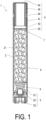
- FIG. 1 is a schematic axial cross-sectional view illustrating an example of a gas generator.
- FIG. 2 is a schematic cross-sectional view for describing a configuration of an igniter assembly and a periphery thereof.
- a gas generator 1 is a columnar device that combusts a gas generating agent accommodated inside and discharges combustion gas to the outside, and can be used for inflating an airbag, for example.
- the gas generator 1 of FIG. 1 includes a housing 2 having a tubular shape, an igniter assembly 3 attached to one axial end side of the housing 2, and a diffuser portion 4 formed on the other end side of the housing 2.
- the igniter assembly 3 is a device that ignites with an ignition current, and is used in an existing gas generator.
- the igniter assembly 3 includes an igniter body 31 that ignites upon receiving supply of a current from the outside, a collar portion 32 made of metal, and a holding portion 33 made of resin fixing the igniter body 31 to the collar portion 32.
- the collar portion 32 is a metal member formed in a tubular shape.
- the collar portion 32 is attached to an opening on one axial end side of the housing 2 by, for example, full circumference welding.
- the collar portion 32 holds the igniter body 31 inside thereof via the holding portion 33.
- the holding portion 33 is interposed between the igniter body 31 and the collar portion 32 by injection molding, and fixes the igniter body 31 with respect to the collar portion 32.
- an inner peripheral surface of the collar portion 32 in touch with the holding portion 33 may be provided with recesses and protrusions.
- the igniter body 31 includes a pair of electro-conductive pins 311, a cup body (igniter cup) 312 having a bottomed tubular shape whose one end is open, a sealing member 313 closing an opening of the cup body 312, and an ignition charge 314 accommodated in an ignition chamber 315, which is a space formed by the cup body 312 and the sealing member 313.
- the pair of electro-conductive pins 311 are connected via a bridge wire (not illustrated) in the ignition chamber 315.
- the bridge wire which is a resistor, generates heat to combust the ignition charge 314.
- the ignition charge 314 is used in an existing gas generator.
- the cup body 312 is a member made of metal in which, for example, resin insulating layers are stacked.
- the sealing member 313 is also made of metal, for example, and is insulated from one of the electro-conductive pins 311.
- the cup body 312 has a radial notch on a surface on the housing 2 side (called an "upper surface” for convenience).
- FIG. 3 is a schematic view of the upper surface of the cup body 312 as viewed in the axial direction of the housing 2 from the housing 2 side.
- two notches 316 crossing substantially at the center of the upper surface are formed in a cross shape.
- the notch 316 guides a position where the cup body 312 fractures during the operation of the igniter body 31.
- an expansion expected part (in other words, the " expansion expected part” before operation) 317 whose peripheral edge is partially defined by the notch 316 expands on a gas generating agent 6 side accommodated in the housing 2.
- three or more notches 316 may be formed to cross at one point, or one expansion expected part provided on the upper surface of the cup body 312 may be open in a side open manner.
- the housing 2 is, for example, a tubular member having a substantially uniform inner diameter and outer diameter, and forms an outer shell container of the gas generator 1.
- the material of the housing 2 is, for example, metal.
- a combustion chamber 21 is formed between the igniter assembly 3 and the diffuser portion 4.
- the combustion chamber 21 accommodates an elastic member 5 such as a coil spring having one end disposed adjacent to the igniter assembly 3, and the gas generating agent 6 accommodated on the other end side of the elastic member 5.
- the elastic member 5 has a tubular outer shape, and the axial direction of the elastic member 5 and the axial direction of the housing 2 are disposed as the same.
- the elastic member 5 is, for example, a compression coil spring.
- One end part 51 of the elastic member 5 has a wire material molded in a circular shape (not illustrated) and is fitted to a side periphery of the igniter assembly 3.
- the one end part 51 of the elastic member 5 is fitted to the side periphery of the collar portion 32, but the one end part 51 may be disposed on the side of the holding portion 33 or the cup body 312 of the igniter body 31.
- the elastic member 5 may be fixed by welding or the like without being fitted to the side periphery of the igniter assembly 3.
- Another end part 52 of the elastic member 5 may have a spiral shape in an axial view in which the elastic member 5 is viewed in the axial direction.
- the interval between the wire materials may have a size not to allow the gas generating agent 6 to pass therethrough.
- the interval between the radially adjacent wire materials has a size smaller than the diameter and length of the gas generating agent such as about 1 mm to 2 mm. In this manner, the elastic member 5 can apply the gas generating agent 6 in a direction of the diffuser portion 4. Since movement of the gas generating agent 6 is limited inside the gas generator 1, it is possible to suppress generation of abnormal noise and crushing of the gas generator 1 due to shaking of the gas generating agent 6.
- a perforated member such as a punched metal, a plain-woven wire mesh, a tatami woven wire mesh, or the like may be disposed at an end of a coil spring or the like. Even in such an aspect, it is possible to hold the gas generating agent 6 in the housing 2 by giving the penetration part a size making it difficult for the gas generating agent 6 to pass therethrough. Also in this case, for example, the diameter or one side of the opening has a size of about 1 mm to 2 mm.
- the elastic member 5 has, inside in the axial direction, a decreased diameter part 53 whose diameter is the smallest.
- the elastic member 5 has a decreased diameter region 54 whose diameter gradually decreases from the one end part 51 toward the decreased diameter part 53, and an increased diameter region 55 whose diameter gradually increases from the decreased diameter part 53 toward the other end part 52.
- the gas generating agent 6 combusts to generate combustion gas.
- the gas generating agent 6 includes a known composition, for example, being formed of, for example, guanidine nitrate (41 wt.%), basic copper nitrate (49 wt.%), a binder, and additives.
- a pellet shape, a disk shape, a columnar shape shape, or a single-hole columnar shape having a through hole can be used.
- the gas generating agent 6 is not limited to those described above.
- the diffuser portion 4 is a tubular portion formed integrally with the housing 2 and closing the other end side of the housing 2. As illustrated in FIG. 1 , for example, the diffuser portion 4 is bottomed tubular and includes a side peripheral surface 41 and a closed end 42 on an opposite side to the combustion chamber 21. A partition wall 7 is disposed between the combustion chamber 21 and the diffuser portion 4. The partition wall 7 is fixed between two plastic work portions 43 whose diameters have decreased by crimping the housing 2, for example.
- the side peripheral surface 41 has a gas discharge port 44.
- the gas discharge port 44 is a through hole, and a plurality of the gas discharge ports 44 are provided along the circumferential direction of the side peripheral surface 41.
- the plurality of gas discharge ports 44 may be provided in the axial direction of the diffuser portion 4.
- the gas discharge port 44 is closed by a closing member (not illustrated) such as a seal tape.
- the closing member is ruptured when the internal pressure of the gas generator 1 is increased by the combustion gas.
- a filter 45 having a tubular shape is accommodated inside the side peripheral surface 41, and the combustion gas discharged from the gas discharge port 44 passes through the filter 45.
- the filter 45 comes into contact with the plastic work portion 43 at the end part of the combustion chamber 21 side, for example, and is held between the plastic work portion 43 and the closed end 42.
- the filter 45 may be, for example, one in which a plain-knitted metal wire material is accommodated in a molding die and compression-molded into a cylindrical shape, and is provided with a through hole in the axial direction.
- the filter 45 may be formed into a columnar shape having a mesh by winding a metal wire material around a rod-shaped core material and thus forming a plurality of layers, and crossing the wire materials with each other.
- the filter 45 may be one in which a sheet-like perforated plate such as an expanded metal, a punched metal, a metallic lath, a plain-woven wire mesh, or a tatami woven wire mesh is wound up in a columnar shape, and provided with a through hole in the axial direction.
- the filter 45 functions as a cooling portion that cools the combustion gas, and filters the combustion gas by filtering combustion residues of the combustion gas.
- the partition wall 7 is a disk-shaped member, for example, and closes between the diffuser portion 4 and the combustion chamber 21.
- the partition wall 7 is disposed in the housing 2 and defines a boundary between the combustion chamber 21 accommodating the gas generating agent 6 and the diffuser portion 4.
- the partition wall 7 may be ruptured by an increase in the internal pressure of the combustion chamber due to the combustion gas, or may include a through hole through which the combustion gas passes.
- a connector (not illustrated) is connected to the pair of electro-conductive pins 311, and power can be supplied to the igniter assembly 3.
- the igniter assembly 3 is operated by an ignition current supplied to electro-conductive pins 311.
- the igniter assembly 3 combusts the ignition charge 314 in the cup body 312 and releases the combustion product to the outside of the cup body 312.
- the gas generating agent 6 in the combustion chamber 21 is ignited by flame or combustion gas that is a combustion product of the ignition charge 314.
- the gas generating agent 6 combusts to generate combustion gas or the like as a combustion product.
- the partition wall 7 When the internal pressure of the combustion chamber 21 increases, the partition wall 7 is ruptured, and the combustion gas passes through the filter 45 of the diffuser portion 4 and is discharged from the gas discharge port 44. Then, the discharged combustion gas inflates an airbag not illustrated, for example.
- FIG. 4 is a cross-sectional view of the igniter assembly and the periphery thereof, illustrating an example of a state where an igniter body is operated.
- the upper surface of the cup body 312 fractures along the notch 316, and the expansion part 317 is open toward the gas generating agent 6.
- the vicinity of the tip end of the expansion part 317 comes into contact with the decreased diameter part 53 of the elastic member 5, and the expansion angle of the expansion part 317 is limited.
- the decreased diameter part 53 is provided at a position in contact with the vicinity of the intersection point of the notch 316 (i.e., the most tip end part on the gas generating agent 6 side when the expansion part 317 expands) in the expansion expected part (the expansion part 317) before the operation of the igniter body 31 during the operation of the igniter body 31, and functions as a regulation portion that regulates the expansion of the expansion part 317 during the operation of the igniter body 31.
- the expansion part 317 not only the vicinity of the tip end of the expansion part 317 but also a part of the expansion part 317 and the decreased diameter part 53 are in contact with each other, whereby the expansion of the expansion part 317 can be regulated.
- a part of the expansion part 317 on the way to the tip end part touches the decreased diameter part 53, and the tip end part relative thereto touches and thus reaches the increased diameter region 55.
- the direction in which the igniter body 31 releases the combustion product is limited by the angle of the expansion part 317 as indicated by the dashed arrow in FIG. 4 , for example. That is, the decreased diameter part 53 suppresses the diffusion of the combustion product of the igniter body 31 in the direction of the inner wall of the housing 2, and the amount guided in the direction of the gas generating agent 6 held in the housing 2 increases. In general, when combustion products of the gas generating agent 6 are dispersed and released at a wide angle, some combustion products touch the housing 2 and are cooled.
- the combustion product of the igniter body 31 suppresses the dispersion of a combustion product and more of them are guided toward the gas generating agent 6, and the ignition performance of the gas generating agent 6 is improved.
- the igniter body 31 and the combustion chamber 21 communicate with each other in a state before operation, and there is no obstacle to the expansion of the expansion part 317.
- the combustion product from the igniter body 31 can ignite the gas generating agent 6 evenly and efficiently.
- the decreased diameter region 54 can also converge the moving direction of the combustion product from the igniter and supply it to the gas generating agent 6, and can increase the flow velocity of the combustion product to improve the ignitability of the gas generating agent 6.
- FIG. 5 is a view for describing the length from the igniter body to the decreased diameter part.
- a length L from the upper surface of the cup body 312 to the decreased diameter part 53 can have a size generally represented by the following formula (1). It should be noted that the length L is a length from the upper surface of the cup body 312 to the decreased diameter part 53 in a state where the elastic member 5 is compressed in the axial direction thereof before operation of the gas generator 1. D / 2 ⁇ L ⁇ D
- the tip end of the expansion part 317 expands by drawing an arc of about the radius (D/2) of the cup body 312 in the direction of the diffuser portion 4 with the peripheral edge of the cup body 312 as a rotation axis. Therefore, the decreased diameter part 53 is preferably provided at a position of about D/2 from the cup body 312.
- the tip end of the expansion part 317 expansion by drawing an arc of about the diameter (D) of the cup body 312 in the direction of the diffuser portion 4 with the part of the peripheral edge of the cup body 312 as a rotation axis. Therefore, the decreased diameter part 53 is preferably provided at a position of about D from the cup body 312. Therefore, the length L from the upper surface of the cup body 312 to the decreased diameter part is preferably set to be approximately equal to or greater than the radius of the cup body 312 and equal to or less than the diameter of the cup body 312 from the cup body 312.
- the elastic member 5 may be formed with the increased diameter region 55 having a lower elastic modulus than the decreased diameter region 54.
- the elastic modulus can be made different by, for example, making a difference in the thickness or the number of turns of the coil spring.
- FIG. 6 is a schematic cross-sectional view of the periphery of the igniter assembly according to the first modified example.
- members corresponding to those of the above-described embodiment are denoted by the same reference signs, and differences will be mainly described.
- a thin dashed line indicates the contour of a cross-sectional shape of the elastic member 5.
- a thick dashed line schematically indicates a cross-sectional shape of the expansion part 317 when ruptured.
- the elastic member 5 is disposed on the side of the holding portion 33. It should be noted that the elastic member 5 may be fitted to the holding portion 33.
- the elastic member 5 has an equal diameter region 56 having a constant diameter on the igniter assembly 3 side.
- the elastic member 5 has the decreased diameter part 53 at a position in contact with the expansion expected part (the expansion part 317) during operation of the igniter body 31, and has the decreased diameter region 54 whose diameter gradually decreases from the vicinity of the upper surface of the cup body 312 toward the decreased diameter part 53 and the increased diameter region 55 whose diameter gradually increases from the decreased diameter part 53 toward the diffuser portion 4.
- FIG. 7 is a schematic cross-sectional view of the periphery of the igniter assembly according to the second modified example.
- a part of the side surface of the collar portion 32 includes a part formed to be flush with the side surface of the holding portion 33.
- the elastic member 5 is disposed on the side of the collar portion 32 and the holding portion 33. It should be noted that the elastic member 5 may be fitted to the collar portion 32 and the holding portion 33. Also in the present modified example, the elastic member 5 has the equal diameter region 56 having a constant diameter on the igniter assembly 3 side.
- the elastic member 5 has the decreased diameter part 53 at a position in contact with the expansion expected part (the expansion part 317) during operation of the igniter body 31, and has the decreased diameter region 54 whose diameter gradually decreases from the vicinity of the upper surface of the cup body 312 toward the decreased diameter part 53 and the increased diameter region 55 whose diameter gradually increases from the decreased diameter part 53 toward the diffuser portion 4.
- FIG. 8 is a schematic cross-sectional view of the periphery of the igniter assembly according to the third modified example.
- the elastic member 5 is disposed on the side of the cup body 312. It should be noted that the elastic member 5 may be fitted to the cup body 312. However, in order to avoid destruction of an insulating layer such as an insulating sheet formed on the surface of the cup body 312, it is preferable to provide a gap between the elastic member 5 and the cup body 312.
- the elastic member 5 has the equal diameter region 56 having a constant diameter on the igniter assembly 3 side.
- the elastic member 5 does not have the decreased diameter region 54.
- the elastic member 5 has the increased diameter region 55 whose diameter gradually increases toward the gas generating agent 6 side at the end part on the diffuser portion 4 side of the equal diameter region 56.
- the vicinity of the tip end of the expansion expected part (the expansion part 317) is in contact with the increased diameter region 55.
- FIG. 9 is a schematic cross-sectional view of the periphery of the igniter assembly according to the fourth modified example.
- the elastic member 5 is disposed on the side of the holding portion 33. It should be noted that the elastic member 5 may be fitted to the holding portion 33.
- the elastic member 5 has the equal diameter region 56 having a constant diameter on the igniter assembly 3 side.
- the elastic member 5 has the decreased diameter part 53 at a position in contact with the expansion expected part (the expansion part 317) during operation of the igniter body 31, and has the decreased diameter region 54 whose diameter gradually decreases from the vicinity of the upper surface of the cup body 312.
- the increased diameter region 55 is also a coil spring, but a perforated member 8 is disposed on the tip end surface (the other end part 52) thereof.
- the perforated member 8 may be a member not having elasticity, and is formed of, for example, a punched metal or a wire mesh.
- FIG. 10 is a schematic cross-sectional view of the periphery of the igniter assembly according to the fifth modified example.
- the elastic member 5 is disposed on the side of the igniter body 31.
- the elastic member 5 includes, for example, one in which three or more leaf springs 57 in the circumferential direction and an annular member 58 disposed along the inner periphery of the housing 2 and connected to the leaf springs 57 are integrally formed.
- a perforated member 9 such as a wire mesh is connected to the diffuser portion 4 side of the annular member 58.
- the perforated member 9 has a circular shape in a transverse cross-sectional view (not illustrated) of the housing 2, and the roughness of the mesh is set not to allow the gas generating agent 6 to pass therethrough.
- the expansion expected part (the expansion part 317) and the annular member 58 may be in contact with each other during operation of the igniter body 31.
- the regulation portion needs not be a part whose diameter is the smallest in the elastic member 5 as long as the regulation portion comes into contact with the ruptured cup body 312.
- the diameter of the elastic member 5 may be constant over the entire length in the axial direction as long as the elastic member 5 includes a regulation portion regulating the direction in which the ruptured cup body 312 expands.
- the igniter body 31 may include a metal charge holder surrounding the ignition charge from the side (radially outside of the housing 2) on the sealing member 313 (on the combustion chamber 21 side).
- one elastic member 5 is disposed between the igniter assembly 3 and the combustion chamber 21.
- the other end part 52 of the elastic member 5 has a spiral shape, an interval part between the radially adjacent wire materials becomes a penetration part (i.e., a gap).
- the space formed inside the elastic member 5 and in which the igniter body 31 is disposed and the space in which the gas generating agent 6 is disposed in the combustion chamber 21 communicate with each other via the penetration part even in a state before operation of the gas generator 1. That is, since the igniter body 31 and the gas generating agent 6 communicate with each other before the operation of the gas generator 1, the combustion product from the ignition charge 314 easily reaches the gas generating agent 6. Therefore, the ignition performance and combustion performance of the gas generating agent 6 are improved.
- the other end part 52 of the spiral shape may have a shape in which the radial center part protrudes on the combustion chamber 21 side or on the igniter body 31 side.
- the cross-sectional shape may be an annular slope or a curved slope from the protruding center part to the peripheral edge of the other end part 52.
- a known transfer charge may be disposed between the igniter body 31 and the gas generating agent 6. Also by doing so, it is possible to improve the ignition performance and combustion performance of the gas generating agent 6.
- the transfer charge may be disposed in a recess recessed on the combustion chamber 21 side.
- the part protruding to the combustion chamber 21 side or the igniter body 31 side is not limited to the radial center part, and a plurality of parts may protrude.
- the partially protruding other end part 52 does not need to have a spiral shape, and may be formed of a perforated member such as an expanded metal, a punched metal, a metallic lath, a plain-woven wire mesh, or a tatami woven wire mesh, and may be used in combination with a coil spring.
- the distance between the axially adjacent wire materials in the increased diameter region 55 may be shorter than the distance between the axially adjacent wire materials in the decreased diameter region 54. That is, the wire material interval in the increased diameter region 55 is made denser than that in the decreased diameter region 54 where the cup body 312 (the expansion part 317) ruptured during the operation of the igniter body 31 faces, and the combustion product can be suppressed from being discharged around the elastic member 5.
Landscapes
- Engineering & Computer Science (AREA)
- Mechanical Engineering (AREA)
- Physics & Mathematics (AREA)
- Fluid Mechanics (AREA)
- General Engineering & Computer Science (AREA)
- Air Bags (AREA)
Abstract
Description
- The present invention relates to a gas generator.
- A gas generator including a long substantially cylindrical housing; a holder fitted to one opening end of the housing, and a closing member fitted to the other end part of the housing to close the other opening end of the housing has been proposed (for example, Patent Document 1). In the present technique, an igniter as an ignition mechanism of a gas generating agent is disposed at one axial end part of the housing. A coil spring includes a large diameter part which is densely wound spirally along an inner wall of the housing, and a decreased diameter part which is sparsely wound at a predetermined interval. The coil spring is provided to apply an elastic force to the gas generating agent while one end part is in contact with the holder and the other end part is in contact with at least a part of a periphery of a through hole on one end side of the gas generating agent.
- Patent Document 1:
JP 2017-7456 A - According to the above-described technique, it is possible to fix a gas generating agent by applying the elastic force to the gas generating agent with a coil spring. On the other hand, when the interval between the igniter and the gas generating agent is widened with the coil spring, there is a risk that the direction in which the combustion product generated by the igniter is released is diffused and does not efficiently reach the gas generating agent. That is, for example, when the combustion product released by the igniter spread, a part thereof collides with an inner wall of the housing.
- An object of the technique of the present disclosure is to improve ignition performance of a gas generating agent in a gas generator.
- A gas generator according to the present disclosure includes: an igniter assembly including an igniter body accommodating an ignition charge, the igniter body including an igniter cup ruptured by a combustion product generated by combustion of the ignition charge and an electro-conductive pin that supplies a current for igniting the ignition charge, a collar portion holding the igniter body, and a holding portion interposed between the igniter body and the collar portion and configured to fix the igniter body to the collar portion, the igniter assembly being configured to release the combustion product; a housing having a tubular shape, the housing including a combustion chamber accommodating a gas generating agent, and including a gas discharge port through which a combustion gas generated by combustion of the gas generating agent is discharged; and an elastic member having a tubular shape, the elastic member being disposed between the igniter assembly and the gas generating agent in the housing with an axial direction of the elastic member being in an axial direction of the housing, the elastic member including a regulation portion at an inner periphery thereof, the regulation portion being configured to regulate a direction in which the igniter cup ruptured expands.
- In this manner, the direction in which the igniter cup expands is regulated by the regulation portion, and the direction in which the combustion product is released during the operation of the igniter body is guided by the igniter cup having expanded. That is, since the direction in which the combustion product is released can be controlled toward the gas generating agent, the ignition performance of the gas generating agent can be improved in the gas generator.
- In
Aspect 1, the igniter cup may include an expansion expected part formed in a rupture surface facing the combustion chamber, the expansion expected part including a peripheral edge a part of which is defined by a notch guiding a position of the igniter cup to be fractured, and the expansion expected part being configured to expand in a state where another part of the peripheral edge is connected to the igniter cup at a time of combustion of the ignition charge, and the regulation portion may be provided at a position in contact with the expansion expected part having expanded. Specifically, such a configuration can be adopted. - In
Aspect - In
Aspect 3, the elastic member may decrease in diameter from a side of the igniter assembly toward the decreased diameter part. Specifically, the regulation portion can be formed by such a configuration. - In
Aspect 3 or 4, the elastic member may increase in diameter from the decreased diameter part toward the other end side of the housing. In this manner, the combustion product can be diffused at a desired angle from the decreased diameter part toward the gas generating agent. - In any of
Aspects 1 to 5, a side of the igniter assembly in the elastic member may be fitted to the collar portion or the holding portion. Specifically, the elastic member can thus be connected to the gas generator. - In any of
Aspects 1 to 6, the elastic member may have a lower elastic modulus on a side of the gas generating agent than on a side of the igniter assembly with respect to the regulation portion as a reference. In this manner, since the distance from the igniter assembly connected to the one end side of the housing to the regulation portion hardly changes, the regulation portion can be disposed at a position designed in advance with respect to the igniter assembly. - In any of
Aspects 1 to 7, the elastic member may be a coil spring. Specifically, such a configuration can be adopted. - The elastic member may include, at an end part on a side of the gas generating agent, a penetration part having a size that allows the combustion product to pass therethrough and does not allow the gas generating agent to pass therethrough, and may apply the gas generating agent to an opposite side of the igniter assembly. In this manner, the elastic member becomes possible to allow the combustion product of the igniter body to pass therethrough and hold the gas generating agent on the combustion chamber side without passing it therethrough.
- The content described in Solution to Problem can be combined as much as possible without departing from the problems and technical ideas of the present disclosure.
- According to the present disclosure, it is possible to improve ignition performance of a gas generating agent in a gas generator.
-
-
FIG. 1 is a schematic axial cross-sectional view illustrating an example of a gas generator. -
FIG. 2 is a schematic cross-sectional view for describing a configuration of an igniter assembly and a periphery thereof. -
FIG. 3 is a schematic view of an upper surface of a cup body as viewed in an axial direction of a housing from the housing side. -
FIG. 4 is a schematic cross-sectional view of the igniter assembly and the periphery thereof illustrating an example of a state where an igniter body is operated. -
FIG. 5 is a view for describing a length from the igniter body to a decreased diameter part. -
FIG. 6 is a schematic cross-sectional view of a periphery of an igniter assembly according to a first modified example. -
FIG. 7 is a schematic cross-sectional view of a periphery of an igniter assembly according to a second modified example. -
FIG. 8 is a schematic cross-sectional view of a periphery of an igniter assembly according to a third modified example. -
FIG. 9 is a schematic cross-sectional view of a periphery of an igniter assembly according to a fourth modified example. -
FIG. 10 is a schematic cross-sectional view of a periphery of an igniter assembly according to a fifth modified example. - Embodiments according to the present disclosure will be described below with reference to the accompanying drawings. It should be noted that the respective configurations and the combinations thereof in the respective embodiments are only examples, and the configurations may be added, omitted, substituted, or otherwise modified as appropriate within a scope that does not depart from the spirit of the present disclosure. The present disclosure is not limited by the embodiments and is limited only by the claims.
-
FIG. 1 is a schematic axial cross-sectional view illustrating an example of a gas generator.FIG. 2 is a schematic cross-sectional view for describing a configuration of an igniter assembly and a periphery thereof. Agas generator 1 is a columnar device that combusts a gas generating agent accommodated inside and discharges combustion gas to the outside, and can be used for inflating an airbag, for example. Thegas generator 1 ofFIG. 1 includes ahousing 2 having a tubular shape, anigniter assembly 3 attached to one axial end side of thehousing 2, and a diffuser portion 4 formed on the other end side of thehousing 2. - The
igniter assembly 3 is a device that ignites with an ignition current, and is used in an existing gas generator. For example, theigniter assembly 3 includes anigniter body 31 that ignites upon receiving supply of a current from the outside, acollar portion 32 made of metal, and a holdingportion 33 made of resin fixing theigniter body 31 to thecollar portion 32. Thecollar portion 32 is a metal member formed in a tubular shape. Thecollar portion 32 is attached to an opening on one axial end side of thehousing 2 by, for example, full circumference welding. Thecollar portion 32 holds theigniter body 31 inside thereof via the holdingportion 33. The holdingportion 33 is interposed between theigniter body 31 and thecollar portion 32 by injection molding, and fixes theigniter body 31 with respect to thecollar portion 32. It should be noted that in order to suppress a circumferential rotation of theigniter body 31 and thecollar portion 32, an inner peripheral surface of thecollar portion 32 in touch with the holdingportion 33 may be provided with recesses and protrusions. - The
igniter body 31 includes a pair of electro-conductive pins 311, a cup body (igniter cup) 312 having a bottomed tubular shape whose one end is open, a sealingmember 313 closing an opening of thecup body 312, and anignition charge 314 accommodated in anignition chamber 315, which is a space formed by thecup body 312 and the sealingmember 313. The pair of electro-conductive pins 311 are connected via a bridge wire (not illustrated) in theignition chamber 315. When the electro-conductive pins 311 are supplied with a current from the outside, the bridge wire, which is a resistor, generates heat to combust theignition charge 314. It should be noted that theignition charge 314 is used in an existing gas generator. Thecup body 312 is a member made of metal in which, for example, resin insulating layers are stacked. The sealingmember 313 is also made of metal, for example, and is insulated from one of the electro-conductive pins 311. Thecup body 312 has a radial notch on a surface on thehousing 2 side (called an "upper surface" for convenience).FIG. 3 is a schematic view of the upper surface of thecup body 312 as viewed in the axial direction of thehousing 2 from thehousing 2 side. On the upper surface of thecup body 312, twonotches 316 crossing substantially at the center of the upper surface are formed in a cross shape. Thenotch 316 guides a position where thecup body 312 fractures during the operation of theigniter body 31. During the operation of theigniter body 31, an expansion expected part (in other words, the " expansion expected part" before operation) 317 whose peripheral edge is partially defined by thenotch 316 expands on agas generating agent 6 side accommodated in thehousing 2. It should be noted that three ormore notches 316 may be formed to cross at one point, or one expansion expected part provided on the upper surface of thecup body 312 may be open in a side open manner. When theignition charge 314 in theignition chamber 315 combusts, thecup body 312 is ruptured with an intersection point of thenotches 316 as a starting point, for example, and a combustion product such as flame and combustion gas are released into thehousing 2. - The
housing 2 is, for example, a tubular member having a substantially uniform inner diameter and outer diameter, and forms an outer shell container of thegas generator 1. The material of thehousing 2 is, for example, metal. Inside thehousing 2, acombustion chamber 21 is formed between theigniter assembly 3 and the diffuser portion 4. Thecombustion chamber 21 accommodates anelastic member 5 such as a coil spring having one end disposed adjacent to theigniter assembly 3, and thegas generating agent 6 accommodated on the other end side of theelastic member 5. Theelastic member 5 has a tubular outer shape, and the axial direction of theelastic member 5 and the axial direction of thehousing 2 are disposed as the same. - The
elastic member 5 is, for example, a compression coil spring. Oneend part 51 of theelastic member 5 has a wire material molded in a circular shape (not illustrated) and is fitted to a side periphery of theigniter assembly 3. In the example ofFIGS. 1 and2 , the oneend part 51 of theelastic member 5 is fitted to the side periphery of thecollar portion 32, but the oneend part 51 may be disposed on the side of the holdingportion 33 or thecup body 312 of theigniter body 31. Theelastic member 5 may be fixed by welding or the like without being fitted to the side periphery of theigniter assembly 3. - Another
end part 52 of theelastic member 5 may have a spiral shape in an axial view in which theelastic member 5 is viewed in the axial direction. In theother end part 52 having the spiral shape, the interval between the wire materials may have a size not to allow thegas generating agent 6 to pass therethrough. For example, the interval between the radially adjacent wire materials has a size smaller than the diameter and length of the gas generating agent such as about 1 mm to 2 mm. In this manner, theelastic member 5 can apply thegas generating agent 6 in a direction of the diffuser portion 4. Since movement of thegas generating agent 6 is limited inside thegas generator 1, it is possible to suppress generation of abnormal noise and crushing of thegas generator 1 due to shaking of thegas generating agent 6. It should be noted that in theother end part 52, a perforated member such as a punched metal, a plain-woven wire mesh, a tatami woven wire mesh, or the like may be disposed at an end of a coil spring or the like. Even in such an aspect, it is possible to hold thegas generating agent 6 in thehousing 2 by giving the penetration part a size making it difficult for thegas generating agent 6 to pass therethrough. Also in this case, for example, the diameter or one side of the opening has a size of about 1 mm to 2 mm. - The
elastic member 5 has, inside in the axial direction, adecreased diameter part 53 whose diameter is the smallest. Theelastic member 5 has a decreaseddiameter region 54 whose diameter gradually decreases from the oneend part 51 toward the decreaseddiameter part 53, and an increaseddiameter region 55 whose diameter gradually increases from the decreaseddiameter part 53 toward theother end part 52. - The
gas generating agent 6 combusts to generate combustion gas. Thegas generating agent 6 includes a known composition, for example, being formed of, for example, guanidine nitrate (41 wt.%), basic copper nitrate (49 wt.%), a binder, and additives. As an individual shape of thegas generating agent 6, for example, a pellet shape, a disk shape, a columnar shape shape, or a single-hole columnar shape having a through hole can be used. However, thegas generating agent 6 is not limited to those described above. - The diffuser portion 4 is a tubular portion formed integrally with the
housing 2 and closing the other end side of thehousing 2. As illustrated inFIG. 1 , for example, the diffuser portion 4 is bottomed tubular and includes a sideperipheral surface 41 and aclosed end 42 on an opposite side to thecombustion chamber 21. Apartition wall 7 is disposed between thecombustion chamber 21 and the diffuser portion 4. Thepartition wall 7 is fixed between twoplastic work portions 43 whose diameters have decreased by crimping thehousing 2, for example. The sideperipheral surface 41 has agas discharge port 44. Thegas discharge port 44 is a through hole, and a plurality of thegas discharge ports 44 are provided along the circumferential direction of the sideperipheral surface 41. It should be noted that the plurality ofgas discharge ports 44 may be provided in the axial direction of the diffuser portion 4. Thegas discharge port 44 is closed by a closing member (not illustrated) such as a seal tape. The closing member is ruptured when the internal pressure of thegas generator 1 is increased by the combustion gas. - A
filter 45 having a tubular shape is accommodated inside the sideperipheral surface 41, and the combustion gas discharged from thegas discharge port 44 passes through thefilter 45. Thefilter 45 comes into contact with theplastic work portion 43 at the end part of thecombustion chamber 21 side, for example, and is held between theplastic work portion 43 and theclosed end 42. Thefilter 45 may be, for example, one in which a plain-knitted metal wire material is accommodated in a molding die and compression-molded into a cylindrical shape, and is provided with a through hole in the axial direction. Thefilter 45 may be formed into a columnar shape having a mesh by winding a metal wire material around a rod-shaped core material and thus forming a plurality of layers, and crossing the wire materials with each other. Thefilter 45 may be one in which a sheet-like perforated plate such as an expanded metal, a punched metal, a metallic lath, a plain-woven wire mesh, or a tatami woven wire mesh is wound up in a columnar shape, and provided with a through hole in the axial direction. When the combustion gas generated by the combustion of thegas generating agent 6 passes through thefilter 45, thefilter 45 functions as a cooling portion that cools the combustion gas, and filters the combustion gas by filtering combustion residues of the combustion gas. - The
partition wall 7 is a disk-shaped member, for example, and closes between the diffuser portion 4 and thecombustion chamber 21. In other words, thepartition wall 7 is disposed in thehousing 2 and defines a boundary between thecombustion chamber 21 accommodating thegas generating agent 6 and the diffuser portion 4. Thepartition wall 7 may be ruptured by an increase in the internal pressure of the combustion chamber due to the combustion gas, or may include a through hole through which the combustion gas passes. - In a state where the
gas generator 1 is assembled to, for example, an airbag of an automobile, a connector (not illustrated) is connected to the pair of electro-conductive pins 311, and power can be supplied to theigniter assembly 3. In this state, when a sensor (not illustrated) mounted on an automobile or the like detects an impact, theigniter assembly 3 is operated by an ignition current supplied to electro-conductive pins 311. Theigniter assembly 3 combusts theignition charge 314 in thecup body 312 and releases the combustion product to the outside of thecup body 312. Thegas generating agent 6 in thecombustion chamber 21 is ignited by flame or combustion gas that is a combustion product of theignition charge 314. Thegas generating agent 6 combusts to generate combustion gas or the like as a combustion product. When the internal pressure of thecombustion chamber 21 increases, thepartition wall 7 is ruptured, and the combustion gas passes through thefilter 45 of the diffuser portion 4 and is discharged from thegas discharge port 44. Then, the discharged combustion gas inflates an airbag not illustrated, for example. -
FIG. 4 is a cross-sectional view of the igniter assembly and the periphery thereof, illustrating an example of a state where an igniter body is operated. InFIG. 4 , the upper surface of thecup body 312 fractures along thenotch 316, and theexpansion part 317 is open toward thegas generating agent 6. At this time, the vicinity of the tip end of theexpansion part 317 comes into contact with the decreaseddiameter part 53 of theelastic member 5, and the expansion angle of theexpansion part 317 is limited. In other words, the decreaseddiameter part 53 is provided at a position in contact with the vicinity of the intersection point of the notch 316 (i.e., the most tip end part on thegas generating agent 6 side when theexpansion part 317 expands) in the expansion expected part (the expansion part 317) before the operation of theigniter body 31 during the operation of theigniter body 31, and functions as a regulation portion that regulates the expansion of theexpansion part 317 during the operation of theigniter body 31. It should be noted that not only the vicinity of the tip end of theexpansion part 317 but also a part of theexpansion part 317 and the decreaseddiameter part 53 are in contact with each other, whereby the expansion of theexpansion part 317 can be regulated. In this case, a part of theexpansion part 317 on the way to the tip end part touches the decreaseddiameter part 53, and the tip end part relative thereto touches and thus reaches the increaseddiameter region 55. - The direction in which the
igniter body 31 releases the combustion product is limited by the angle of theexpansion part 317 as indicated by the dashed arrow inFIG. 4 , for example. That is, the decreaseddiameter part 53 suppresses the diffusion of the combustion product of theigniter body 31 in the direction of the inner wall of thehousing 2, and the amount guided in the direction of thegas generating agent 6 held in thehousing 2 increases. In general, when combustion products of thegas generating agent 6 are dispersed and released at a wide angle, some combustion products touch thehousing 2 and are cooled. On the other hand, according to the present embodiment, the combustion product of theigniter body 31 suppresses the dispersion of a combustion product and more of them are guided toward thegas generating agent 6, and the ignition performance of thegas generating agent 6 is improved. In particular, theigniter body 31 and thecombustion chamber 21 communicate with each other in a state before operation, and there is no obstacle to the expansion of theexpansion part 317. Furthermore, the combustion product from theigniter body 31 can ignite thegas generating agent 6 evenly and efficiently. It should be noted that, the decreaseddiameter region 54 can also converge the moving direction of the combustion product from the igniter and supply it to thegas generating agent 6, and can increase the flow velocity of the combustion product to improve the ignitability of thegas generating agent 6. By adjusting the inclination angle of the increaseddiameter region 55 in advance, it is possible to release the combustion product to diffuse to the entire end part on theigniter assembly 3 side of thegas generating agent 6. In a case where a coil spring is used as theelastic member 5, if a plurality of coil springs are connected in the axial direction, the touch or the contact point between the end parts of the coil springs is shifted, an inclination occurs in the coil springs, and there is a risk of being difficult to transmit the combustion product to thecombustion chamber 21 side. Use of one coil spring can cause the combustion product to be circulated as designed. -
FIG. 5 is a view for describing the length from the igniter body to the decreased diameter part. As indicated by an arrow inFIG. 5 , when the diameter of the upper surface of thecup body 312 is D, a length L from the upper surface of thecup body 312 to the decreaseddiameter part 53 can have a size generally represented by the following formula (1). It should be noted that the length L is a length from the upper surface of thecup body 312 to the decreaseddiameter part 53 in a state where theelastic member 5 is compressed in the axial direction thereof before operation of thegas generator 1.
- When the upper surface of the
cup body 312 fractures along thenotch 316 provided radially from the center thereof, the tip end of theexpansion part 317 expands by drawing an arc of about the radius (D/2) of thecup body 312 in the direction of the diffuser portion 4 with the peripheral edge of thecup body 312 as a rotation axis. Therefore, the decreaseddiameter part 53 is preferably provided at a position of about D/2 from thecup body 312. When the entire upper surface of thecup body 312 fractures with a part of the peripheral edge left and expands in a side open manner, the tip end of theexpansion part 317 expansion by drawing an arc of about the diameter (D) of thecup body 312 in the direction of the diffuser portion 4 with the part of the peripheral edge of thecup body 312 as a rotation axis. Therefore, the decreaseddiameter part 53 is preferably provided at a position of about D from thecup body 312. Therefore, the length L from the upper surface of thecup body 312 to the decreased diameter part is preferably set to be approximately equal to or greater than the radius of thecup body 312 and equal to or less than the diameter of thecup body 312 from thecup body 312. - It should be noted that the
elastic member 5 may be formed with the increaseddiameter region 55 having a lower elastic modulus than the decreaseddiameter region 54. The elastic modulus can be made different by, for example, making a difference in the thickness or the number of turns of the coil spring. In this manner, in a state where thegas generator 1 is filled with thegas generating agent 6, even if there is a slight variation in the amount of thegas generating agent 6, the increaseddiameter region 55 is preferentially deformed, and the length of the decreaseddiameter region 54 becomes substantially constant. That is, the length from theigniter body 31 to the decreaseddiameter part 53 becomes substantially constant, and the tip end of the rupturedcup body 312 and the decreaseddiameter part 53 of theelastic member 5 come into contact with each other in a positional relationship designed in advance. -
FIG. 6 is a schematic cross-sectional view of the periphery of the igniter assembly according to the first modified example. In the modified example, members corresponding to those of the above-described embodiment are denoted by the same reference signs, and differences will be mainly described. A thin dashed line indicates the contour of a cross-sectional shape of theelastic member 5. A thick dashed line schematically indicates a cross-sectional shape of theexpansion part 317 when ruptured. In the example ofFIG. 6 , theelastic member 5 is disposed on the side of the holdingportion 33. It should be noted that theelastic member 5 may be fitted to the holdingportion 33. Theelastic member 5 has anequal diameter region 56 having a constant diameter on theigniter assembly 3 side. Theelastic member 5 has the decreaseddiameter part 53 at a position in contact with the expansion expected part (the expansion part 317) during operation of theigniter body 31, and has the decreaseddiameter region 54 whose diameter gradually decreases from the vicinity of the upper surface of thecup body 312 toward the decreaseddiameter part 53 and the increaseddiameter region 55 whose diameter gradually increases from the decreaseddiameter part 53 toward the diffuser portion 4. -
FIG. 7 is a schematic cross-sectional view of the periphery of the igniter assembly according to the second modified example. In the example ofFIG. 7 , a part of the side surface of thecollar portion 32 includes a part formed to be flush with the side surface of the holdingportion 33. Theelastic member 5 is disposed on the side of thecollar portion 32 and the holdingportion 33. It should be noted that theelastic member 5 may be fitted to thecollar portion 32 and the holdingportion 33. Also in the present modified example, theelastic member 5 has theequal diameter region 56 having a constant diameter on theigniter assembly 3 side. Theelastic member 5 has the decreaseddiameter part 53 at a position in contact with the expansion expected part (the expansion part 317) during operation of theigniter body 31, and has the decreaseddiameter region 54 whose diameter gradually decreases from the vicinity of the upper surface of thecup body 312 toward the decreaseddiameter part 53 and the increaseddiameter region 55 whose diameter gradually increases from the decreaseddiameter part 53 toward the diffuser portion 4. -
FIG. 8 is a schematic cross-sectional view of the periphery of the igniter assembly according to the third modified example. In the example ofFIG. 8 , theelastic member 5 is disposed on the side of thecup body 312. It should be noted that theelastic member 5 may be fitted to thecup body 312. However, in order to avoid destruction of an insulating layer such as an insulating sheet formed on the surface of thecup body 312, it is preferable to provide a gap between theelastic member 5 and thecup body 312. Theelastic member 5 has theequal diameter region 56 having a constant diameter on theigniter assembly 3 side. Theelastic member 5 does not have the decreaseddiameter region 54. That is, theelastic member 5 has the increaseddiameter region 55 whose diameter gradually increases toward thegas generating agent 6 side at the end part on the diffuser portion 4 side of theequal diameter region 56. During the operation of theigniter body 31, the vicinity of the tip end of the expansion expected part (the expansion part 317) is in contact with the increaseddiameter region 55. -
FIG. 9 is a schematic cross-sectional view of the periphery of the igniter assembly according to the fourth modified example. In the example ofFIG. 9 , theelastic member 5 is disposed on the side of the holdingportion 33. It should be noted that theelastic member 5 may be fitted to the holdingportion 33. Theelastic member 5 has theequal diameter region 56 having a constant diameter on theigniter assembly 3 side. Theelastic member 5 has the decreaseddiameter part 53 at a position in contact with the expansion expected part (the expansion part 317) during operation of theigniter body 31, and has the decreaseddiameter region 54 whose diameter gradually decreases from the vicinity of the upper surface of thecup body 312. In the present modified example, the increaseddiameter region 55 is also a coil spring, but aperforated member 8 is disposed on the tip end surface (the other end part 52) thereof. Theperforated member 8 may be a member not having elasticity, and is formed of, for example, a punched metal or a wire mesh. -
FIG. 10 is a schematic cross-sectional view of the periphery of the igniter assembly according to the fifth modified example. In the example ofFIG. 10 , theelastic member 5 is disposed on the side of theigniter body 31. It should be noted that theelastic member 5 includes, for example, one in which three ormore leaf springs 57 in the circumferential direction and anannular member 58 disposed along the inner periphery of thehousing 2 and connected to theleaf springs 57 are integrally formed. A perforated member 9 such as a wire mesh is connected to the diffuser portion 4 side of theannular member 58. The perforated member 9 has a circular shape in a transverse cross-sectional view (not illustrated) of thehousing 2, and the roughness of the mesh is set not to allow thegas generating agent 6 to pass therethrough. In the present modified example, the expansion expected part (the expansion part 317) and theannular member 58 may be in contact with each other during operation of theigniter body 31. - Each aspect disclosed in the present specification can be combined with any other feature disclosed herein. The regulation portion needs not be a part whose diameter is the smallest in the
elastic member 5 as long as the regulation portion comes into contact with theruptured cup body 312. The diameter of theelastic member 5 may be constant over the entire length in the axial direction as long as theelastic member 5 includes a regulation portion regulating the direction in which the rupturedcup body 312 expands. - As illustrated in
FIG. 3 ofJP 2002-79903 A igniter body 31 may include a metal charge holder surrounding the ignition charge from the side (radially outside of the housing 2) on the sealing member 313 (on thecombustion chamber 21 side). - As illustrated in the embodiment and the modified example, it is preferable that one
elastic member 5 is disposed between theigniter assembly 3 and thecombustion chamber 21. When theother end part 52 of theelastic member 5 has a spiral shape, an interval part between the radially adjacent wire materials becomes a penetration part (i.e., a gap). At this time, it is preferable that the space formed inside theelastic member 5 and in which theigniter body 31 is disposed and the space in which thegas generating agent 6 is disposed in thecombustion chamber 21 communicate with each other via the penetration part even in a state before operation of thegas generator 1. That is, since theigniter body 31 and thegas generating agent 6 communicate with each other before the operation of thegas generator 1, the combustion product from theignition charge 314 easily reaches thegas generating agent 6. Therefore, the ignition performance and combustion performance of thegas generating agent 6 are improved. - The
other end part 52 of the spiral shape may have a shape in which the radial center part protrudes on thecombustion chamber 21 side or on theigniter body 31 side. The cross-sectional shape may be an annular slope or a curved slope from the protruding center part to the peripheral edge of theother end part 52. In this manner, the ignition surface of thegas generating agent 6 facing theigniter body 31 can be widened, and the ignition performance can be improved. It should be noted that a known transfer charge may be disposed between theigniter body 31 and thegas generating agent 6. Also by doing so, it is possible to improve the ignition performance and combustion performance of thegas generating agent 6. For example, by causing the radial center part of theother end part 52 of theelastic member 5 to protrude on theigniter body 31 side, the transfer charge may be disposed in a recess recessed on thecombustion chamber 21 side. It should be noted that the part protruding to thecombustion chamber 21 side or theigniter body 31 side is not limited to the radial center part, and a plurality of parts may protrude. The partially protrudingother end part 52 does not need to have a spiral shape, and may be formed of a perforated member such as an expanded metal, a punched metal, a metallic lath, a plain-woven wire mesh, or a tatami woven wire mesh, and may be used in combination with a coil spring. - In the
elastic member 5, which is a coil spring, the distance between the axially adjacent wire materials in the increaseddiameter region 55 may be shorter than the distance between the axially adjacent wire materials in the decreaseddiameter region 54. That is, the wire material interval in the increaseddiameter region 55 is made denser than that in the decreaseddiameter region 54 where the cup body 312 (the expansion part 317) ruptured during the operation of theigniter body 31 faces, and the combustion product can be suppressed from being discharged around theelastic member 5. -
- 1 Gas generator
- 2 Housing
- 21 Combustion chamber
- 3 Igniter assembly
- 31 Igniter body
- 311 Electro-conductive pin
- 312 Cup body
- 313 Sealing member
- 314 Ignition charge
- 315 Ignition chamber
- 316 Notch
- 317 Expansion part
- 32 Collar portion
- 33 Holding portion
- 4 Diffuser portion
- 41 Side peripheral surface
- 42 Closed end
- 43 Plastic work portion
- 44 Gas discharge port
- 45 Filter
- 5 Elastic member
- 51 One end part
- 52 Other end part
- 53 Decreased diameter part
- 54 Decreased diameter region
- 55 Increased diameter region
- 56 Equal diameter region
- 57 Leaf spring
- 58 Annular member
- 6 Gas generating agent
- 7 Partition wall
- 8 Perforated member
- 9 Perforated member
Claims (9)
- A gas generator, comprising:an igniter assembly including,an igniter body accommodating an ignition charge, the igniter body including an igniter cup ruptured by a combustion product generated by combustion of the ignition charge and an electro-conductive pin that supplies a current for igniting the ignition charge,a collar portion holding the igniter body, anda holding portion interposed between the igniter body and the collar portion and configured to fix the igniter body to the collar portion,the igniter assembly being configured to release the combustion product;a housing having a tubular shape, the housing including a combustion chamber accommodating a gas generating agent to be ignited by the combustion product, and including a gas discharge port through which a combustion gas generated by combustion of the gas generating agent is discharged; andan elastic member having a tubular shape, the elastic member being disposed between the igniter assembly and the gas generating agent in the housing with an axial direction of the elastic member being in a same direction as an axial direction of the housing, the elastic member including a regulation portion at an inner periphery thereof, the regulation portion being configured to regulate a direction in which the igniter cup ruptured expands.
- The gas generator according to claim 1, whereinthe igniter cup includes an expansion expected part formed in a rupture surface facing the combustion chamber, the expansion expected part including a peripheral edge, a part of which is defined by a notch guiding a position of the igniter cup to be fractured, the expansion expected part being configured to expand in a state where another part of the peripheral edge is connected to the igniter cup at a time of combustion of the ignition charge, andthe regulation portion is provided at a position in contact with the expansion expected part that expands.
- The gas generator according to claim 1 or 2, wherein
the regulation portion is a decreased diameter part where an inner diameter of the elastic member is smallest. - The gas generator according to claim 3, wherein
the elastic member decreases in diameter from a side of the igniter assembly toward the decreased diameter part. - The gas generator according to claim 3 or 4, wherein
the elastic member increases in diameter from the decreased diameter part toward a side of the gas generating agent. - The gas generator according to any one of claims 1 to 5, wherein
a side of the igniter assembly in the elastic member is fitted to the collar portion or the holding portion. - The gas generator according to any one of claims 1 to 6, wherein
the elastic member has a lower elastic modulus on a side of the gas generating agent than on a side of the igniter assembly with respect to the regulation portion as a reference. - The gas generator according to any one of claims 1 to 7, wherein
the elastic member is a coil spring. - The gas generator according to any one of claims 1 to 8, wherein
the elastic member includes, at an end part on a side of the gas generating agent, a penetration part having a size that allows the combustion product to pass therethrough and does not allow the gas generating agent to pass therethrough, and applies the gas generating agent to an opposite side of the igniter assembly.
Applications Claiming Priority (2)
| Application Number | Priority Date | Filing Date | Title |
|---|---|---|---|
| JP2021154424 | 2021-09-22 | ||
| PCT/JP2022/033023 WO2023047915A1 (en) | 2021-09-22 | 2022-09-01 | Gas generator |
Publications (2)
| Publication Number | Publication Date |
|---|---|
| EP4406788A1 true EP4406788A1 (en) | 2024-07-31 |
| EP4406788A4 EP4406788A4 (en) | 2025-09-03 |
Family
ID=85720547
Family Applications (1)
| Application Number | Title | Priority Date | Filing Date |
|---|---|---|---|
| EP22872671.7A Pending EP4406788A4 (en) | 2021-09-22 | 2022-09-01 | GAS GENERATOR |
Country Status (5)
| Country | Link |
|---|---|
| US (1) | US12496996B2 (en) |
| EP (1) | EP4406788A4 (en) |
| JP (1) | JP7781168B2 (en) |
| CN (1) | CN117980194A (en) |
| WO (1) | WO2023047915A1 (en) |
Cited By (1)
| Publication number | Priority date | Publication date | Assignee | Title |
|---|---|---|---|---|
| US20250091544A1 (en) * | 2022-06-06 | 2025-03-20 | Daicel Corporation | Gas generator |
Families Citing this family (3)
| Publication number | Priority date | Publication date | Assignee | Title |
|---|---|---|---|---|
| WO2022196228A1 (en) * | 2021-03-19 | 2022-09-22 | 日本化薬株式会社 | Gas generator |
| JP7765363B2 (en) * | 2022-08-26 | 2025-11-06 | 日本化薬株式会社 | Gas generator |
| DE102022124029A1 (en) | 2022-09-20 | 2024-03-21 | Zf Airbag Germany Gmbh | Gas generator |
Family Cites Families (9)
| Publication number | Priority date | Publication date | Assignee | Title |
|---|---|---|---|---|
| JP4864234B2 (en) | 2000-06-22 | 2012-02-01 | 株式会社ダイセル | Gas generator for airbag |
| US9440615B2 (en) * | 2014-12-10 | 2016-09-13 | Autoliv Asp, Inc. | Initiator assemblies |
| JP2017007456A (en) | 2015-06-19 | 2017-01-12 | 日本化薬株式会社 | Gas generator |
| DE102015012703A1 (en) * | 2015-10-02 | 2017-04-06 | Trw Airbag Systems Gmbh | GAS GENERATOR, PARTICULARLY FOR A VEHICLE SAFETY SYSTEM, SPACERS FOR ARRANGEMENT IN A GAS GENERATOR, GASSACK MODULE AND VEHICLE ABSORPTION SYSTEM |
| DE112017002069B4 (en) * | 2016-04-18 | 2023-05-25 | Nippon Kayaku Kabushiki Kaisha | Gas generator with self-igniting means |
| DE102018112011A1 (en) * | 2018-05-18 | 2019-11-21 | Trw Airbag Systems Gmbh | FUEL CAGE FOR A PIPE GAS GENERATOR, FUEL BODY ELEMENT FOR A PIPE GAS GENERATOR, PIPE GAS GENERATOR FOR A GASSACK MODULE, GAS TANK MODULE, VEHICLE SAFETY SYSTEM, METHOD FOR OPERATING AND PRODUCING A PIPE GAS GENERATOR |
| JP7436297B2 (en) * | 2020-06-15 | 2024-02-21 | 日本化薬株式会社 | gas generator |
| WO2022196228A1 (en) * | 2021-03-19 | 2022-09-22 | 日本化薬株式会社 | Gas generator |
| US12403860B2 (en) * | 2021-12-14 | 2025-09-02 | Nippon Kayaku Kabushiki Kaisha | Gas generator |
-
2022
- 2022-09-01 EP EP22872671.7A patent/EP4406788A4/en active Pending
- 2022-09-01 JP JP2023549445A patent/JP7781168B2/en active Active
- 2022-09-01 CN CN202280063446.1A patent/CN117980194A/en active Pending
- 2022-09-01 WO PCT/JP2022/033023 patent/WO2023047915A1/en not_active Ceased
-
2024
- 2024-03-18 US US18/608,009 patent/US12496996B2/en active Active
Cited By (1)
| Publication number | Priority date | Publication date | Assignee | Title |
|---|---|---|---|---|
| US20250091544A1 (en) * | 2022-06-06 | 2025-03-20 | Daicel Corporation | Gas generator |
Also Published As
| Publication number | Publication date |
|---|---|
| WO2023047915A1 (en) | 2023-03-30 |
| CN117980194A (en) | 2024-05-03 |
| JPWO2023047915A1 (en) | 2023-03-30 |
| US12496996B2 (en) | 2025-12-16 |
| JP7781168B2 (en) | 2025-12-05 |
| US20240217474A1 (en) | 2024-07-04 |
| EP4406788A4 (en) | 2025-09-03 |
Similar Documents
| Publication | Publication Date | Title |
|---|---|---|
| EP4406788A1 (en) | Gas generator | |
| EP2957468B1 (en) | Gas generator | |
| KR102093194B1 (en) | Gas generation apparatus and method for assembling same | |
| JP7597965B2 (en) | Gas generator | |
| EP2952394A1 (en) | Gas generator | |
| EP3056265B1 (en) | Gas generator | |
| JP7849182B2 (en) | gas generator | |
| US12214741B2 (en) | Gas generator | |
| JPWO2023047915A5 (en) | ||
| EP4442516A1 (en) | Gas generator | |
| US20190047508A1 (en) | Gas generator, in particular for a vehicle occupant protection system, spring for arranging in a gas generator, airbag module, and vehicle occupant protection system | |
| US11173868B2 (en) | Gas generator | |
| EP1731384A1 (en) | Gas generator | |
| JP7636233B2 (en) | Gas generator | |
| JP2017081343A (en) | Gas generator | |
| JP2017007456A (en) | Gas generator | |
| JP6250434B2 (en) | Gas generator | |
| JP4644296B2 (en) | Gas generator | |
| CN116802088A (en) | The gas generator | |
| JP7665503B2 (en) | Gas generator | |
| JP7587443B2 (en) | Igniters and gas generators | |
| WO2019230503A1 (en) | Gas generator | |
| JP7238302B2 (en) | gas generator | |
| JP6084095B2 (en) | Gas generator | |
| JP2017087961A (en) | Gas generator |
Legal Events
| Date | Code | Title | Description |
|---|---|---|---|
| STAA | Information on the status of an ep patent application or granted ep patent |
Free format text: STATUS: THE INTERNATIONAL PUBLICATION HAS BEEN MADE |
|
| PUAI | Public reference made under article 153(3) epc to a published international application that has entered the european phase |
Free format text: ORIGINAL CODE: 0009012 |
|
| STAA | Information on the status of an ep patent application or granted ep patent |
Free format text: STATUS: REQUEST FOR EXAMINATION WAS MADE |
|
| 17P | Request for examination filed |
Effective date: 20240321 |
|
| AK | Designated contracting states |
Kind code of ref document: A1 Designated state(s): AL AT BE BG CH CY CZ DE DK EE ES FI FR GB GR HR HU IE IS IT LI LT LU LV MC MK MT NL NO PL PT RO RS SE SI SK SM TR |
|
| DAV | Request for validation of the european patent (deleted) | ||
| DAX | Request for extension of the european patent (deleted) | ||
| A4 | Supplementary search report drawn up and despatched |
Effective date: 20250805 |
|
| RIC1 | Information provided on ipc code assigned before grant |
Ipc: B60R 21/264 20060101AFI20250730BHEP Ipc: F42B 3/04 20060101ALI20250730BHEP |