EP4406783A1 - An interior trim assembly of a vehicle, and a vehicle comprising such an interior trim assembly - Google Patents
An interior trim assembly of a vehicle, and a vehicle comprising such an interior trim assembly Download PDFInfo
- Publication number
- EP4406783A1 EP4406783A1 EP23153035.3A EP23153035A EP4406783A1 EP 4406783 A1 EP4406783 A1 EP 4406783A1 EP 23153035 A EP23153035 A EP 23153035A EP 4406783 A1 EP4406783 A1 EP 4406783A1
- Authority
- EP
- European Patent Office
- Prior art keywords
- carrier
- trim assembly
- interior trim
- décor layer
- vacuum
- Prior art date
- Legal status (The legal status is an assumption and is not a legal conclusion. Google has not performed a legal analysis and makes no representation as to the accuracy of the status listed.)
- Granted
Links
Images





Classifications
-
- B—PERFORMING OPERATIONS; TRANSPORTING
- B60—VEHICLES IN GENERAL
- B60R—VEHICLES, VEHICLE FITTINGS, OR VEHICLE PARTS, NOT OTHERWISE PROVIDED FOR
- B60R13/00—Elements for body-finishing, identifying, or decorating; Arrangements or adaptations for advertising purposes
- B60R13/02—Internal Trim mouldings ; Internal Ledges; Wall liners for passenger compartments; Roof liners
-
- G—PHYSICS
- G06—COMPUTING OR CALCULATING; COUNTING
- G06F—ELECTRIC DIGITAL DATA PROCESSING
- G06F3/00—Input arrangements for transferring data to be processed into a form capable of being handled by the computer; Output arrangements for transferring data from processing unit to output unit, e.g. interface arrangements
- G06F3/01—Input arrangements or combined input and output arrangements for interaction between user and computer
- G06F3/02—Input arrangements using manually operated switches, e.g. using keyboards or dials
- G06F3/0202—Constructional details or processes of manufacture of the input device
-
- G—PHYSICS
- G06—COMPUTING OR CALCULATING; COUNTING
- G06F—ELECTRIC DIGITAL DATA PROCESSING
- G06F3/00—Input arrangements for transferring data to be processed into a form capable of being handled by the computer; Output arrangements for transferring data from processing unit to output unit, e.g. interface arrangements
- G06F3/01—Input arrangements or combined input and output arrangements for interaction between user and computer
- G06F3/048—Interaction techniques based on graphical user interfaces [GUI]
- G06F3/0487—Interaction techniques based on graphical user interfaces [GUI] using specific features provided by the input device, e.g. functions controlled by the rotation of a mouse with dual sensing arrangements, or of the nature of the input device, e.g. tap gestures based on pressure sensed by a digitiser
- G06F3/0488—Interaction techniques based on graphical user interfaces [GUI] using specific features provided by the input device, e.g. functions controlled by the rotation of a mouse with dual sensing arrangements, or of the nature of the input device, e.g. tap gestures based on pressure sensed by a digitiser using a touch-screen or digitiser, e.g. input of commands through traced gestures
- G06F3/04886—Interaction techniques based on graphical user interfaces [GUI] using specific features provided by the input device, e.g. functions controlled by the rotation of a mouse with dual sensing arrangements, or of the nature of the input device, e.g. tap gestures based on pressure sensed by a digitiser using a touch-screen or digitiser, e.g. input of commands through traced gestures by partitioning the display area of the touch-screen or the surface of the digitising tablet into independently controllable areas, e.g. virtual keyboards or menus
-
- B—PERFORMING OPERATIONS; TRANSPORTING
- B60—VEHICLES IN GENERAL
- B60R—VEHICLES, VEHICLE FITTINGS, OR VEHICLE PARTS, NOT OTHERWISE PROVIDED FOR
- B60R13/00—Elements for body-finishing, identifying, or decorating; Arrangements or adaptations for advertising purposes
- B60R13/02—Internal Trim mouldings ; Internal Ledges; Wall liners for passenger compartments; Roof liners
- B60R2013/0287—Internal Trim mouldings ; Internal Ledges; Wall liners for passenger compartments; Roof liners integrating other functions or accessories
-
- G—PHYSICS
- G06—COMPUTING OR CALCULATING; COUNTING
- G06F—ELECTRIC DIGITAL DATA PROCESSING
- G06F2203/00—Indexing scheme relating to G06F3/00 - G06F3/048
- G06F2203/048—Indexing scheme relating to G06F3/048
- G06F2203/04809—Textured surface identifying touch areas, e.g. overlay structure for a virtual keyboard
Definitions
- the present disclosure relates to an interior trim assembly of a vehicle. Moreover, the present disclosure relates to a vehicle comprising such an interior trim assembly.
- Such functions may be the activation of a window lifter, of the interior illumination, of the air condition, of a sound system or adjustment of rear-view mirrors.
- Next to the activation of the functions many of them comprise parameters that may be set.
- air conditioning such parameters are the temperature of the air inside the vehicle that should be conditioned to or the intensity of the fans that circulate the air.
- a sound system settable parameters may relate to the volume and the acoustics.
- Modern vehicles are also equipped with a number of devices or systems which enhance the vehicle maneuver. These devices or systems may include lighting systems, driver assistance systems, communication systems, monitoring systems, air flow systems, energy absorbers or any other functional devices or systems. Such systems and devices may be manually controlled by activating or deactivating various parameters.
- buttons or sensors located inside the vehicle interior trim parts are buttons or sensors located inside the vehicle interior trim parts.
- the surface of interior trim parts In recent approaches the activation and setting of vehicle-related functions are included into the surface of interior trim parts.
- the surface In some of the interior trim parts, the surface includes protrusions for indicating the location of buttons or sensors for controlling various parameters of the vehicle.
- the interior trim parts are made of surface having morphing functionality. That is to say, the protrusions appear on the surface of the interior trim part when activated.
- a complex mechanism such as an actuator is required for pushing the portion of the surface which enables the protrusions to appear on the surface of the trim part.
- Figs.1a and 1b One such system is shown in Figs.1a and 1b .
- the system of Figs.1a and 1b comprises an actuator (not shown) placed vertically below the buttons/sensors 106.
- the actuator pushes the buttons/sensors 106 upward, which ultimately pushes the surface of the trim part, which enables the protrusions to appear on the surface.
- the drawback of such systems is that, it requires a complex pushing mechanism such as an actuator.
- the displacement of the buttons is required to be substantial to observe the protrusion on the surface since the marked radius of the protrusion is not well defined in case of pushing up mechanism.
- US10338682 B2 Another apparatus is disclosed in US10338682 B2 , which comprises a method and apparatus for providing multi-point haptic feedback texture systems.
- the drawback of this apparatus is that collapsible or top surface of the apparatus is prone to damage and hence have short life span, since the collapsible or top surface is directly disposed on a surface pattern without any supporting material.
- the interior trim part includes the compressible material disposed between the carrier and the décor layer.
- the compressible material provides support to the décor layer.
- the compressible material being in direct contact with the décor layer, provides uniform pressure to the décor layer, which leads to uniform deformation of the décor layer towards the carrier.
- the protrusions formed on outer surface of the décor layer has well defined and marked radius since the décor layer moves towards the carrier instead of the button pushing the décor layer upward as compared to the prior art.
- a small displacement of the décor layer is sufficient for good appearance of protrusions on the outer surface of the décor layer.
- the interior trim assembly does not include any complex pushing mechanism such as an actuator. Instead, the interior trim assembly includes a simple vacuum unit for movement of the décor layer.
- the interior trim part is simple, reliable and cost effective.
- vehicle denotes any motor driven vehicle with or without trailers driven be a driver, where the driver requires information about persons, other vehicles or objects in the (near) surrounding of the vehicle to be able to drive safety.
- vehicles are cars, trucks, tractors or trailers.
- the term "décor layer” denotes an outermost layer of the interior trim assembly which is exposed to interior of the vehicle.
- the décor layer may be smooth during non-operational condition, i.e. when the vacuum is not applied between the décor layer and the carrier, and the protrusions appear on the surface of the décor layer during operational condition, i.e. when the vacuum is applied between the décor layer and the carrier.
- carrier denotes a rigid structure which provides support to the interior trim assembly.
- the carrier may be a part of the vehicle component such as a door or an instrument panel or a dashboard of the vehicle.
- the carrier is configured to hold the components of the interior trim assembly in place and provides rigidity to the assembly.
- compressible material denotes a material having low density, which can be easily compressed when pressure is applied and gets decompressed when pressure is released.
- vacuum unit denotes a device for creating vacuum or negative pressure within an enclosure.
- the interior trim assembly comprises an air sealing layer configured between an inner surface of the décor layer and the compressible material.
- the air sealing layer prevents any pressure leakage between the décor layer and the compressible material and thus enhances the vacuum performance without any pressure losses.
- the interior trim assembly comprises a non-compressible grid disposed between the carrier and the compressible material.
- the non-compressible grid may be made of a mesh like structure for providing support to the compressible material.
- the non-compressible grid provides support to the compressible material when the vacuum is applied, such that it prevents the compressible material from dislocation.
- the décor layer is configured to move at the non-protruded portion of the carrier. This enables the appearance of protrusion on the surface of the décor layer which indicates the position of buttons/sensors.
- the carrier is made of a translucent material such as PC or PMMA or translucent polyolefin plastics for transmission of light through the carrier.
- the carrier is made of an opaque material such as ABS-PC, ABS or PP.
- the carrier further comprises at least one vacuum duct connecting the at least one hole of the carrier with the vacuum unit. This configuration can be used to connect multiple holes of the carrier with one vacuum unit.
- the décor layer is made of PVC or PU or TPO or other sealed stretchable materials such as textile.
- the décor layer is disposed on the carrier by using adhesive, themoplastic or thermodur glue or adhesive foils.
- the compressible material comprises foam based on PUR, PE or silicon or polyester based 3D spacer.
- the vacuum unit has operating pressure between -0.5 bar to -1 bar.
- Another aspect of the present disclosure is directed to a vehicle, comprising an interior trim assembly according to one of the embodiments previously discussed.
- the technical effects and advantages as discussed with regard to the present interior trim assembly equally apply to the vehicle.
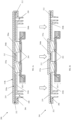
- FIG 1a shows a sectional view of a conventional trim part 100.
- the trim part 100 comprises a housing 102, buttons 106 mounted on the housing 102, a carrier 104 for supporting the buttons 106 and a décor layer 108 disposed over the carrier 104 and the buttons 106.
- the trim part 100 also comprises actuator(s) (not shown) for pushing the buttons 106 in an upward direction.
- the actuator pushes the buttons 106 upward
- the décor layer 108 being in direct contact with the buttons 106 also moves upward as shown in Figure 1b .
- protrusions on the surface of the décor layer 108 appear when actuator is activated.
- the drawback of the trim part 100 is that it requires a complex pushing mechanism such as an actuator.
- the displacement of the buttons 106 is required to be substantial to observe the protrusion on the surface since the marked radius of the protrusion is not well defined in case of pushing up mechanism.
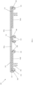
- FIG. 2a shows a sectional view of an interior trim assembly 200.
- the trim assembly 200 comprises a housing 202.
- the housing 202 may be disposed on a vehicle part, such as a door trim, center console, dashboard or instrument panel of the vehicle.
- the trim assembly 200 further comprises at least one button 204 mounted on the housing 202.
- the at least one button 204 may be replaced by at least one sensor.
- the trim assembly 200 may comprise both button and sensor.
- the trim assembly 200 further comprises a carrier 206.
- the carrier 206 may have at least one protruded portion 206a and at least one non-protruded portion 206b.
- the at least one protruded portion 206a of the carrier 206 is located vertically above each of the at least one button 204.
- the carrier 206 further comprises at least one hole 208 located at the at least one non-protruded portion 206b.
- the carrier 206 may be made of a translucent material such as PC or PMMA or translucent polyolefin plastics for light transmission. Such translucent material for carrier 206 is used when light transmission is required through the carrier 206 such as in case of illuminated trim parts.
- the carrier 206 may be made of opaque material such as ABS-PC, ABS or PP.
- the trim assembly 200 further comprises a décor layer 210.
- the décor layer 210 has an inner surface 210a and an outer surface 210b.
- the inner surface 210a of the décor layer 210 is configured to be disposed on the carrier 206 by using adhesive, Themoplastic or Thermodur glue or adhesive foils.
- the outer surface 210b of the décor layer 210 is exposed outside for user input.
- the décor layer 210 is made of PVC or PU or TPO or other sealed stretchable materials such as textile.
- the trim assembly 200 further comprises a compressible material 212.
- the compressible material 212 disposed between the carrier 206 and the décor layer 210 at the at least one non-protruded portion 206b of the carrier 206.
- the compressible material 212 comprises foam based on PUR, PE or silicon or polyester based 3D spacer.
- the compressible material 212 is configured to be compressed (shown in figure 2b ) when vacuum is applied, and decompressed when the vacuum is withdrawn.
- Figure 2b shows a sectional view of the trim assembly 200 when protrusions appear on the décor layer 210.
- the décor layer 210 is configured to move towards the carrier 206 at least partially when vacuum is applied between the carrier 206 and the inner surface 210a of the décor layer 210.
- the décor layer 210 is configured to move towards the carrier 206 at the non-protruded portion 206b of the carrier 206. Portions of the décor layer 210 which are above the protruded portion 206a of the carrier 206 remain in place, thus forming protrusions on the outer surface 210b of the décor layer 210.
- FIG. 3 shows the trim assembly 200 as described in the above embodiment.
- the housing 202 and at least one button 204 are not shown in figure 3 .
- the trim assembly 200 further comprises a vacuum unit 214.
- the vacuum unit 214 comprises a vacuum tank 216 and a vacuum pump 218.
- the vacuum unit 214 is connected to the carrier 206 via the at least one hole 208 of the carrier 206.
- the vacuum unit 214 is configured to apply vacuum between the carrier 206 and the décor layer 210.
- the vacuum unit 214 may have an operating pressure between -0.5 bar to -1 bar.
- the compressible material 212 gets compressed and the portion of the décor layer 210 configured above the protruded portion 206a of the carrier 206 moves downward, forming the protrusions on the décor layer.
- the compressible material 212 regains its original shape and the décor layer 210 moves back to its original position, thus the protrusions on the décor layer disappears.
- FIGs 4 and 5 show the trim assembly 200 as described in the above embodiment.
- the housing 202 and at least one button 204 are not shown in figures 4 and 5 .
- the trim assembly 200 further comprises an air sealing layer 220 configured between the inner surface 210a of the décor layer 210 and the compressible material 212 as shown in figure 4 .
- the air sealing layer 220 is configured to provide air sealing effect between the carrier 206 and décor layer 210.
- the air sealing layer 220 is configured to prevent pressure leak and provide air sealed enclosure between the carrier 206 and the décor layer 210.
- the air sealing layer 220 enhances the vacuum performance without any pressure losses.
- the air sealing layer 220 may be made of closed PE, or PUR thin Foam.
- the air sealing layer 220 may be glued on the inner surface 210a of the décor layer 210. Alternatively, the glue itself may be used as an air sealing layer depending on the nature and texture of decor layer 210.
- the trim assembly 200 further comprises a non-compressible grid 222 disposed between the carrier 206 and the compressible material 212 as shown in figure 5 .
- the non-compressible grid 222 may be made of a mesh like structure for providing support to the compressible material 212.
- the non-compressible grid 222 may provide support to the compressible material 212 when the vacuum is applied, thus preventing the compressible material 212 from dislocation.
- the non-compressible grid 222 may be glued on the carrier 206 and/or on the bottom of the compressible material 212.
- the non-compressible grid 222 is configured to allow air / pressure to pass through.
- the non-compressible grid 222 may be made of material which allows air to pass through such as Metal grid, or pet fabric.
- a grained structure may be provided on the top surface of the carrier 206 below the compressible material 212 to promote vacuum creation.
- the non-compressible grid 222 may not be used in case the at least one hole 408 (shown in Fig. 8a and 8b ) is small.
- FIG. 6 shows a sectional view of an interior trim assembly 300 according to another embodiment of the present disclosure.
- the trim assembly 300 of this embodiment is same as the embodiment described in the above embodiments except the design of the carrier 306.
- the carrier 306 comprises at least one vacuum duct 324 connected to the vacuum unit 214 (shown in figure 3 ).
- the at least one vacuum duct 324 is configured to connect at least one hole 308 of the carrier 306 with the vacuum unit 214.
- each of the non-protruded portion 306b of the carrier 306 is connected to the at least one vacuum duct 324.
- the advantage of such a configuration is that a uniform distribution of vacuum throughout the non-protruded portion 306b of the carrier is possible.
- Figures 7a to 7c show perspective views of an interior trim assembly 400 according to another embodiment of the present disclosure.
- Figure 7a shows the trim assembly 400 with the décor layer removed.
- the trim assembly 400 comprises a carrier 406, at least one button 404 and a vacuum duct 424.
- the vacuum duct 424 may be connected to a vacuum unit 214 (shown in figure 3 ).
- the vacuum duct 424 may be connected to the at least one hole (not visible) of the carrier 406.
- Figure 7b shows the trim assembly 400 with a décor layer 410 wrapped over the carrier 406 such that the at least one button 404 is not visible from outside.
- Figure 7b also shows that the décor layer 410 has a smooth appearance without any protrusions on the décor layer 410.
- Figure 7c shows the trim assembly 400 with a décor layer 410 wrapped over the carrier 406 such that the at least one button 404 is not directly visible from outside, but the protrusions appear on the décor layer 410.
- Figure 7c also illustrate a state of the trim assembly 400 when the vacuum is applied between the carrier 406 and the inner surface of the décor layer 410.
- Figures 8a and 8b show sectional views of the trim assembly 400 of figures 7a-7c .
- Figure 8a illustrates the trim assembly 400 when the décor layer 410 has smooth appearance and no protrusions appear on the décor layer 410.
- the trim assembly 400 of this embodiment has same operating principle as the previous embodiments described above with some design modifications in the carrier 406 which are described herein.
- the trim assembly 400 comprises the carrier 406 which comprises the vacuum duct 424 configured within the carrier 406.
- the vacuum duct 424 is connected to at least one hole 408 of the carrier 406.
- the trim assembly 400 further comprises at least one button 404 and a décor layer 410 disposed on the carrier 406.
- a compressible material 412 is disposed between the carrier 406 and the décor layer 410.
- Figure 8b illustrates the trim assembly 400 when the décor layer 410 has protrusions.
- the compressible material 412 gets compressed and the décor layer 410 is configured to move towards the carrier 406 when the vacuum is applied.
- Embodiment of the present disclosure also discloses a vehicle comprising the interior trim assembly 200, 300, 400.
Landscapes
- Engineering & Computer Science (AREA)
- General Engineering & Computer Science (AREA)
- Theoretical Computer Science (AREA)
- Human Computer Interaction (AREA)
- Physics & Mathematics (AREA)
- General Physics & Mathematics (AREA)
- Mechanical Engineering (AREA)
- Vehicle Interior And Exterior Ornaments, Soundproofing, And Insulation (AREA)
Abstract
Description
- The present disclosure relates to an interior trim assembly of a vehicle. Moreover, the present disclosure relates to a vehicle comprising such an interior trim assembly.
- In modern vehicles the number of available vehicle-related functions is constantly increasing. Such functions may be the activation of a window lifter, of the interior illumination, of the air condition, of a sound system or adjustment of rear-view mirrors. Next to the activation of the functions many of them comprise parameters that may be set. In case of air conditioning such parameters are the temperature of the air inside the vehicle that should be conditioned to or the intensity of the fans that circulate the air. In case of a sound system settable parameters may relate to the volume and the acoustics.
- Modern vehicles are also equipped with a number of devices or systems which enhance the vehicle maneuver. These devices or systems may include lighting systems, driver assistance systems, communication systems, monitoring systems, air flow systems, energy absorbers or any other functional devices or systems. Such systems and devices may be manually controlled by activating or deactivating various parameters.
- In many cases the activation and the setting are done by means of buttons or sensors located inside the vehicle interior trim parts.
- In recent approaches the activation and setting of vehicle-related functions are included into the surface of interior trim parts. In some of the interior trim parts, the surface includes protrusions for indicating the location of buttons or sensors for controlling various parameters of the vehicle. However, in recent approaches of enhancing the aesthetic appeal and beautification of the interior of the vehicle, the interior trim parts are made of surface having morphing functionality. That is to say, the protrusions appear on the surface of the interior trim part when activated. In such systems a complex mechanism such as an actuator is required for pushing the portion of the surface which enables the protrusions to appear on the surface of the trim part. One such system is shown in
Figs.1a and 1b . - The system of
Figs.1a and 1b comprises an actuator (not shown) placed vertically below the buttons/sensors 106. On activation, the actuator pushes the buttons/sensors 106 upward, which ultimately pushes the surface of the trim part, which enables the protrusions to appear on the surface. The drawback of such systems is that, it requires a complex pushing mechanism such as an actuator. Also, the displacement of the buttons is required to be substantial to observe the protrusion on the surface since the marked radius of the protrusion is not well defined in case of pushing up mechanism. - Another apparatus is disclosed in
US10338682 B2 - It is an object of the present disclosure to provide an interior trim assembly by which the drawbacks as mentioned above can be eliminated or at least reduced. In particular, it is one task to provide an interior trim assembly that reduces the use of complex pushing mechanism such as an actuator. It is also an object of the present disclosure to provide an interior trim assembly which has simple and reliable components and is cost effective. Moreover, the present disclosure has the object to provide a vehicle comprising such an interior trim assembly.
- The objects are achieved by the features specified in claim 1. Advantageous embodiments are the subject of the dependent claims.
- According to one embodiment of the present disclosure an interior trim assembly for a vehicle comprising:
- a carrier having at least one protruded portion and at least one non-protruded portion, wherein the carrier has at least one hole configured at the non-protruded portion;
- at least one of a button and a sensor disposed on the carrier at the at least one protruded portion, wherein the at least one of a button and a sensor is configured to receive input from a user;
- a décor layer disposed on the carrier, wherein an outer surface of the décor layer is visible to the user;
- compressible material disposed between the carrier and the décor layer at the at least one non-protruded portion of the carrier; and
- a vacuum unit connected to the at least one hole of the carrier, wherein the vacuum unit is configured to create vacuum between the carrier and the décor layer,
- According to the present disclosure the interior trim part includes the compressible material disposed between the carrier and the décor layer. The compressible material provides support to the décor layer. When the vacuum is applied, the compressible material being in direct contact with the décor layer, provides uniform pressure to the décor layer, which leads to uniform deformation of the décor layer towards the carrier. Another advantage of the present disclosure is that the protrusions formed on outer surface of the décor layer has well defined and marked radius since the décor layer moves towards the carrier instead of the button pushing the décor layer upward as compared to the prior art. Another advantage of the present disclosure is that a small displacement of the décor layer is sufficient for good appearance of protrusions on the outer surface of the décor layer. Another advantage of the present disclosure is that the interior trim assembly does not include any complex pushing mechanism such as an actuator. Instead, the interior trim assembly includes a simple vacuum unit for movement of the décor layer. Thus, the interior trim part is simple, reliable and cost effective.
- The term "vehicle" denotes any motor driven vehicle with or without trailers driven be a driver, where the driver requires information about persons, other vehicles or objects in the (near) surrounding of the vehicle to be able to drive safety. As an example, vehicles are cars, trucks, tractors or trailers.
- The term "décor layer" denotes an outermost layer of the interior trim assembly which is exposed to interior of the vehicle. The décor layer may be smooth during non-operational condition, i.e. when the vacuum is not applied between the décor layer and the carrier, and the protrusions appear on the surface of the décor layer during operational condition, i.e. when the vacuum is applied between the décor layer and the carrier.
- The term "carrier" denotes a rigid structure which provides support to the interior trim assembly. The carrier may be a part of the vehicle component such as a door or an instrument panel or a dashboard of the vehicle. The carrier is configured to hold the components of the interior trim assembly in place and provides rigidity to the assembly.
- The term "compressible material" denotes a material having low density, which can be easily compressed when pressure is applied and gets decompressed when pressure is released.
- The term "vacuum unit" denotes a device for creating vacuum or negative pressure within an enclosure.
- In another embodiment the interior trim assembly comprises an air sealing layer configured between an inner surface of the décor layer and the compressible material. The air sealing layer prevents any pressure leakage between the décor layer and the compressible material and thus enhances the vacuum performance without any pressure losses.
- In another embodiment the interior trim assembly comprises a non-compressible grid disposed between the carrier and the compressible material. The non-compressible grid may be made of a mesh like structure for providing support to the compressible material. In particular, the non-compressible grid provides support to the compressible material when the vacuum is applied, such that it prevents the compressible material from dislocation.
- In another embodiment the décor layer is configured to move at the non-protruded portion of the carrier. This enables the appearance of protrusion on the surface of the décor layer which indicates the position of buttons/sensors.
- In another embodiment the carrier is made of a translucent material such as PC or PMMA or translucent polyolefin plastics for transmission of light through the carrier.
- In another embodiment the carrier is made of an opaque material such as ABS-PC, ABS or PP.
- In another embodiment the carrier further comprises at least one vacuum duct connecting the at least one hole of the carrier with the vacuum unit. This configuration can be used to connect multiple holes of the carrier with one vacuum unit.
- In another embodiment the décor layer is made of PVC or PU or TPO or other sealed stretchable materials such as textile.
- In another embodiment the décor layer is disposed on the carrier by using adhesive, themoplastic or thermodur glue or adhesive foils.
- In another embodiment the compressible material comprises foam based on PUR, PE or silicon or polyester based 3D spacer.
- In another embodiment the vacuum unit has operating pressure between -0.5 bar to -1 bar.
- Another aspect of the present disclosure is directed to a vehicle, comprising an interior trim assembly according to one of the embodiments previously discussed. The technical effects and advantages as discussed with regard to the present interior trim assembly equally apply to the vehicle.
- The present disclosure is described in detail with reference to the drawings attached wherein
- Figures 1a and 1b
- illustrate sectional views of a trim part, according to prior art,
- Figures 2a and 2b
- illustrate sectional views of an interior trim assembly according to an embodiment of the present disclosure,
- Figure 3
- illustrates a sectional view of the interior trim assembly of
Figure 2 and a vacuum unit, according to an embodiment of the present disclosure, - Figure 4
- illustrates a sectional view of an interior trim assembly, according to another embodiment of the present disclosure,
- Figure 5
- illustrates a sectional view of an interior trim assembly, according to another embodiment of the present disclosure,
- Figure 6
- illustrates a sectional view of an interior trim assembly, according to another embodiment of the present disclosure,
- Figures 7a - 7c
- illustrate perspective views of an interior trim assembly, according to another embodiment of the present disclosure,
- Figures 8a and 8b
- illustrate sectional views of the interior trim assembly, according to the embodiment of
Figure 7 . -
Figure 1a shows a sectional view of a conventionaltrim part 100. Thetrim part 100 comprises ahousing 102,buttons 106 mounted on thehousing 102, acarrier 104 for supporting thebuttons 106 and adécor layer 108 disposed over thecarrier 104 and thebuttons 106. Thetrim part 100 also comprises actuator(s) (not shown) for pushing thebuttons 106 in an upward direction. When the actuator pushes thebuttons 106 upward, thedécor layer 108 being in direct contact with thebuttons 106 also moves upward as shown inFigure 1b . Thus, protrusions on the surface of thedécor layer 108 appear when actuator is activated. The drawback of thetrim part 100 is that it requires a complex pushing mechanism such as an actuator. Also, the displacement of thebuttons 106 is required to be substantial to observe the protrusion on the surface since the marked radius of the protrusion is not well defined in case of pushing up mechanism. -
Figure 2a shows a sectional view of an interiortrim assembly 200. Thetrim assembly 200 comprises ahousing 202. Thehousing 202 may be disposed on a vehicle part, such as a door trim, center console, dashboard or instrument panel of the vehicle. Thetrim assembly 200 further comprises at least onebutton 204 mounted on thehousing 202. In an embodiment the at least onebutton 204 may be replaced by at least one sensor. In another embodiment thetrim assembly 200 may comprise both button and sensor. Thetrim assembly 200 further comprises acarrier 206. Thecarrier 206 may have at least one protrudedportion 206a and at least onenon-protruded portion 206b. The at least one protrudedportion 206a of thecarrier 206 is located vertically above each of the at least onebutton 204. Thecarrier 206 further comprises at least onehole 208 located at the at least onenon-protruded portion 206b. Thecarrier 206 may be made of a translucent material such as PC or PMMA or translucent polyolefin plastics for light transmission. Such translucent material forcarrier 206 is used when light transmission is required through thecarrier 206 such as in case of illuminated trim parts. In another embodiment, thecarrier 206 may be made of opaque material such as ABS-PC, ABS or PP. - The
trim assembly 200 further comprises adécor layer 210. Thedécor layer 210 has aninner surface 210a and anouter surface 210b. Theinner surface 210a of thedécor layer 210 is configured to be disposed on thecarrier 206 by using adhesive, Themoplastic or Thermodur glue or adhesive foils. Theouter surface 210b of thedécor layer 210 is exposed outside for user input. Thedécor layer 210 is made of PVC or PU or TPO or other sealed stretchable materials such as textile. - The
trim assembly 200 further comprises acompressible material 212. Thecompressible material 212 disposed between thecarrier 206 and thedécor layer 210 at the at least onenon-protruded portion 206b of thecarrier 206. Thecompressible material 212 comprises foam based on PUR, PE or silicon or polyester based 3D spacer. Thecompressible material 212 is configured to be compressed (shown infigure 2b ) when vacuum is applied, and decompressed when the vacuum is withdrawn. -
Figure 2b shows a sectional view of thetrim assembly 200 when protrusions appear on thedécor layer 210. As shown infigure 2 , thedécor layer 210 is configured to move towards thecarrier 206 at least partially when vacuum is applied between thecarrier 206 and theinner surface 210a of thedécor layer 210. Thedécor layer 210 is configured to move towards thecarrier 206 at thenon-protruded portion 206b of thecarrier 206. Portions of thedécor layer 210 which are above the protrudedportion 206a of thecarrier 206 remain in place, thus forming protrusions on theouter surface 210b of thedécor layer 210. -
Figure 3 shows thetrim assembly 200 as described in the above embodiment. Thehousing 202 and at least onebutton 204 are not shown infigure 3 . Thetrim assembly 200 further comprises avacuum unit 214. Thevacuum unit 214 comprises avacuum tank 216 and avacuum pump 218. Thevacuum unit 214 is connected to thecarrier 206 via the at least onehole 208 of thecarrier 206. Thevacuum unit 214 is configured to apply vacuum between thecarrier 206 and thedécor layer 210. Thevacuum unit 214 may have an operating pressure between -0.5 bar to -1 bar. When the vacuum is applied, thecompressible material 212 gets compressed and the portion of thedécor layer 210 configured above the protrudedportion 206a of thecarrier 206 moves downward, forming the protrusions on the décor layer. When the vacuum is withdrawn, thecompressible material 212 regains its original shape and thedécor layer 210 moves back to its original position, thus the protrusions on the décor layer disappears. -
Figures 4 and 5 show thetrim assembly 200 as described in the above embodiment. Thehousing 202 and at least onebutton 204 are not shown infigures 4 and 5 . Thetrim assembly 200 further comprises anair sealing layer 220 configured between theinner surface 210a of thedécor layer 210 and thecompressible material 212 as shown infigure 4 . Theair sealing layer 220 is configured to provide air sealing effect between thecarrier 206 anddécor layer 210. Theair sealing layer 220 is configured to prevent pressure leak and provide air sealed enclosure between thecarrier 206 and thedécor layer 210. Thus, theair sealing layer 220 enhances the vacuum performance without any pressure losses. Theair sealing layer 220 may be made of closed PE, or PUR thin Foam. Theair sealing layer 220 may be glued on theinner surface 210a of thedécor layer 210. Alternatively, the glue itself may be used as an air sealing layer depending on the nature and texture ofdecor layer 210. Thetrim assembly 200 further comprises anon-compressible grid 222 disposed between thecarrier 206 and thecompressible material 212 as shown infigure 5 . Thenon-compressible grid 222 may be made of a mesh like structure for providing support to thecompressible material 212. Thenon-compressible grid 222 may provide support to thecompressible material 212 when the vacuum is applied, thus preventing thecompressible material 212 from dislocation. Thenon-compressible grid 222 may be glued on thecarrier 206 and/or on the bottom of thecompressible material 212. Thenon-compressible grid 222 is configured to allow air / pressure to pass through. Thenon-compressible grid 222 may be made of material which allows air to pass through such as Metal grid, or pet fabric. Alternatively, a grained structure may be provided on the top surface of thecarrier 206 below thecompressible material 212 to promote vacuum creation. Thenon-compressible grid 222 may not be used in case the at least one hole 408 (shown inFig. 8a and 8b ) is small. -
Figure 6 shows a sectional view of an interiortrim assembly 300 according to another embodiment of the present disclosure. Thetrim assembly 300 of this embodiment is same as the embodiment described in the above embodiments except the design of thecarrier 306. Thecarrier 306 comprises at least onevacuum duct 324 connected to the vacuum unit 214 (shown infigure 3 ). The at least onevacuum duct 324 is configured to connect at least onehole 308 of thecarrier 306 with thevacuum unit 214. In this embodiment, each of thenon-protruded portion 306b of thecarrier 306 is connected to the at least onevacuum duct 324. The advantage of such a configuration is that a uniform distribution of vacuum throughout thenon-protruded portion 306b of the carrier is possible. -
Figures 7a to 7c show perspective views of an interiortrim assembly 400 according to another embodiment of the present disclosure.Figure 7a shows thetrim assembly 400 with the décor layer removed. Thetrim assembly 400 comprises acarrier 406, at least onebutton 404 and avacuum duct 424. Thevacuum duct 424 may be connected to a vacuum unit 214 (shown infigure 3 ). Thevacuum duct 424 may be connected to the at least one hole (not visible) of thecarrier 406. -
Figure 7b shows thetrim assembly 400 with adécor layer 410 wrapped over thecarrier 406 such that the at least onebutton 404 is not visible from outside.Figure 7b also shows that thedécor layer 410 has a smooth appearance without any protrusions on thedécor layer 410. -
Figure 7c shows thetrim assembly 400 with adécor layer 410 wrapped over thecarrier 406 such that the at least onebutton 404 is not directly visible from outside, but the protrusions appear on thedécor layer 410.Figure 7c also illustrate a state of thetrim assembly 400 when the vacuum is applied between thecarrier 406 and the inner surface of thedécor layer 410. -
Figures 8a and 8b show sectional views of thetrim assembly 400 offigures 7a-7c .Figure 8a illustrates thetrim assembly 400 when thedécor layer 410 has smooth appearance and no protrusions appear on thedécor layer 410. Thetrim assembly 400 of this embodiment has same operating principle as the previous embodiments described above with some design modifications in thecarrier 406 which are described herein. Thetrim assembly 400 comprises thecarrier 406 which comprises thevacuum duct 424 configured within thecarrier 406. Thevacuum duct 424 is connected to at least onehole 408 of thecarrier 406. Thetrim assembly 400 further comprises at least onebutton 404 and adécor layer 410 disposed on thecarrier 406. Acompressible material 412 is disposed between thecarrier 406 and thedécor layer 410. -
Figure 8b illustrates thetrim assembly 400 when thedécor layer 410 has protrusions. Thecompressible material 412 gets compressed and thedécor layer 410 is configured to move towards thecarrier 406 when the vacuum is applied. - Embodiment of the present disclosure also discloses a vehicle comprising the interior
trim assembly - Although the subject matter of the present disclosure has been described in language specific to structural features and/or acts, it is to be understood that the subject matter defined in the appended claims is not necessarily limited to the specific features or acts described above. Rather, the specific features and acts described above are disclosed as examples of implementing the claims and other equivalent features and acts are intended to be within the scope of the claims, i.e. the features disclosed in the foregoing description, the claims, and the drawings may be essential, both individually and in any combination, for accomplishing the present disclosure in its various embodiments. The embodiments shown herein are only examples of the present disclosure and must therefore not be understood as being restrictive. Alternative embodiments considered by the skilled person are equally covered by the scope of protection of the present disclosure.
-
- 100
- trim part of prior art
- 102
- housing of prior art
- 104
- carrier of prior art
- 106
- buttons of prior art
- 108
- décor layer of prior art
- 200
- trim assembly according to one embodiment
- 202
- housing
- 204
- at least one button
- 206
- carrier
- 206a
- protruded portion of carrier
- 206b
- non-protruded portion of carrier
- 208
- at least one hole
- 210
- décor layer
- 210a
- inner surface of décor layer
- 210b
- outer surface of décor layer
- 212
- compressible material
- 214
- vacuum unit
- 216
- vacuum tank
- 218
- vacuum pump
- 220
- air sealing layer
- 222
- non-compressible grid
- 300
- trim assembly according to another embodiment
- 306
- carrier
- 306a
- protruded portion of carrier
- 306b
- non-protruded portion of carrier
- 308
- at least one hole
- 324
- vacuum duct
- 400
- trim assembly according to another embodiment
- 404
- at least one button
- 406
- carrier
- 408
- at least one hole
- 410
- décor layer
- 412
- compressible material
- 424
- vacuum duct
Claims (12)
- An interior trim assembly (200, 300, 400) for a vehicle comprising:- a carrier (206, 306, 406) having at least one protruded portion (206a, 306a) and at least one non-protruded portion (206b, 306b), wherein the carrier (206, 306, 406) has at least one hole (208, 308, 408) configured at the non-protruded portion (206b, 306b);- at least one of a button (204, 404) and a sensor disposed on the carrier (206, 306, 406) at the at least one protruded portion (206a, 306a), wherein the at least one of the button (204, 404) and the sensor is configured to receive input from a user;- a décor layer (210, 410) disposed on the carrier (206, 306, 406), wherein an outer surface (210b) of the décor layer (210, 410) is visible to the user;- compressible material (212, 412) disposed between the carrier (206, 306, 406) and the décor layer (210, 410) at the at least one non-protruded portion (206b, 306b) of the carrier (206, 306, 406); and- a vacuum unit (214) connected to the at least one hole (208, 308, 408) of the carrier (206, 306, 406), wherein the vacuum unit (214) is configured to create vacuum between the carrier (206, 306, 406) and the décor layer (210, 410),wherein the compressible material (212, 412) is configured to be compressed or decompressed when the vacuum is applied or withdrawn between the carrier (206, 306, 406) and the décor layer (210, 410), and wherein the décor layer (210, 410) is configured to move towards or away from the carrier (206, 306, 406) when the vacuum is applied or withdrawn between the carrier (206, 306, 406) and the décor layer (210, 410).
- The interior trim assembly (200) as claimed in claim 1, further comprises an air sealing layer (220) configured between an inner surface (210a) of the décor layer (210) and the compressible material (212).
- The interior trim assembly (200) as claimed in claim 1, further comprises a non-compressible grid (222) disposed between the carrier (206) and the compressible material (212) .
- The interior trim assembly (200, 300, 400) as claimed in claim 1, wherein the décor layer (210, 410) is configured to move at the non-protruded portion (206b, 306b) of the carrier (206, 306, 406).
- The interior trim assembly (200, 300, 400) as claimed in claim 1, wherein the carrier (206, 306, 406) is made of a translucent material such as PC or PMMA or translucent polyolefin plastics for transmission of light through the carrier (206, 306, 406).
- The interior trim assembly (200, 300, 400) as claimed in claim 1, wherein the carrier (206, 306, 406) is made of an opaque material such as ABS-PC, ABS or PP.
- The interior trim assembly (300, 400) as claimed in claim 1, wherein the carrier (306, 406) further comprises at least one vacuum duct (324, 424) connecting the at least one hole (308, 408) of the carrier (306, 406) with the vacuum unit (214).
- The interior trim assembly (200, 300, 400) as claimed in claim 1, wherein the décor layer (210, 410) is made of PVC or PU or TPO or other sealed stretchable materials such as textile.
- The interior trim assembly (200, 300, 400) as claimed in claim 1, wherein the décor layer (210, 410) is disposed on the carrier (206, 306, 406) by using adhesive made of Themoplastic or Thermodur glue or adhesive foils.
- The interior trim assembly (200, 300, 400) as claimed in claim 1, wherein the compressible material (212, 412) comprises foam based on PUR, PE or silicon or polyester based 3D spacer.
- The interior trim assembly (200, 300, 400) as claimed in claim 1, wherein the vacuum unit (214) has operating pressure between -0.5 bar to -1 bar.
- A vehicle, comprising an interior trim assembly (200, 300, 400) according to one of the preceding claims.
Priority Applications (2)
| Application Number | Priority Date | Filing Date | Title |
|---|---|---|---|
| ES23153035T ES3055991T3 (en) | 2023-01-24 | 2023-01-24 | An interior trim assembly of a vehicle, and a vehicle comprising such an interior trim assembly |
| EP23153035.3A EP4406783B1 (en) | 2023-01-24 | 2023-01-24 | An interior trim assembly of a vehicle, and a vehicle comprising such an interior trim assembly |
Applications Claiming Priority (1)
| Application Number | Priority Date | Filing Date | Title |
|---|---|---|---|
| EP23153035.3A EP4406783B1 (en) | 2023-01-24 | 2023-01-24 | An interior trim assembly of a vehicle, and a vehicle comprising such an interior trim assembly |
Publications (2)
| Publication Number | Publication Date |
|---|---|
| EP4406783A1 true EP4406783A1 (en) | 2024-07-31 |
| EP4406783B1 EP4406783B1 (en) | 2025-09-17 |
Family
ID=85076237
Family Applications (1)
| Application Number | Title | Priority Date | Filing Date |
|---|---|---|---|
| EP23153035.3A Active EP4406783B1 (en) | 2023-01-24 | 2023-01-24 | An interior trim assembly of a vehicle, and a vehicle comprising such an interior trim assembly |
Country Status (2)
| Country | Link |
|---|---|
| EP (1) | EP4406783B1 (en) |
| ES (1) | ES3055991T3 (en) |
Citations (1)
| Publication number | Priority date | Publication date | Assignee | Title |
|---|---|---|---|---|
| US20180143689A1 (en) * | 2008-04-02 | 2018-05-24 | Immersion Corporation | Method and Apparatus for Providing Multi-Point Haptic Feedback Texture Systems |
Family Cites Families (1)
| Publication number | Priority date | Publication date | Assignee | Title |
|---|---|---|---|---|
| DE102017213797A1 (en) * | 2017-08-08 | 2019-02-14 | Benecke-Kaliko Ag | Component with a shape-variable surface and method for its production |
-
2023
- 2023-01-24 ES ES23153035T patent/ES3055991T3/en active Active
- 2023-01-24 EP EP23153035.3A patent/EP4406783B1/en active Active
Patent Citations (2)
| Publication number | Priority date | Publication date | Assignee | Title |
|---|---|---|---|---|
| US20180143689A1 (en) * | 2008-04-02 | 2018-05-24 | Immersion Corporation | Method and Apparatus for Providing Multi-Point Haptic Feedback Texture Systems |
| US10338682B2 (en) | 2008-04-02 | 2019-07-02 | Immersion Corporation | Method and apparatus for providing multi-point haptic feedback texture systems |
Also Published As
| Publication number | Publication date |
|---|---|
| ES3055991T3 (en) | 2026-02-17 |
| EP4406783B1 (en) | 2025-09-17 |
Similar Documents
| Publication | Publication Date | Title |
|---|---|---|
| US7385308B2 (en) | Advanced automotive control switches | |
| US6129406A (en) | Dashboard | |
| US10649133B2 (en) | Lighting system for an interior module | |
| KR100263129B1 (en) | A lid for an air bag | |
| US7237797B2 (en) | Instrument panel having modular airbag door assembly | |
| KR102101754B1 (en) | switch device for vehicle | |
| US6899381B1 (en) | Vehicle headliner with a flexible duct | |
| EP2539182B1 (en) | Vehicle interior trim panel with an ultrasound sensor | |
| CN111098568A (en) | Membrane and hidden switch structure comprising same | |
| CN113545107B (en) | vehicle interior parts | |
| US20180170251A1 (en) | Vehicle glass roof with light controls and interior lights | |
| US6565115B2 (en) | Invisible airbag door | |
| EP4406783A1 (en) | An interior trim assembly of a vehicle, and a vehicle comprising such an interior trim assembly | |
| US20240416731A1 (en) | Sun visor assembly for a vehicle interior and motor vehicle comprising such a sun visor assembly | |
| JP2006517890A (en) | Device comprising a hard support reinforcement and flexible padding and a vehicle having the device | |
| JPH11512564A (en) | Armrest electric switch array | |
| CN116061837A (en) | Operating device for vehicle | |
| CN214355850U (en) | Headliner for vehicle | |
| US20240399784A1 (en) | Method and filling tool for producing a decorative element with a functional body and a plain decorative element | |
| JP3033582U (en) | Driver side airbag device | |
| DE69515859D1 (en) | Vehicle seat and method for its manufacture | |
| CN115916514A (en) | Molded part with a transmissive surface layer and method for producing a molded part with a transmissive surface layer | |
| US20110127807A1 (en) | Roof assemblies for vehicles including moon roof assemblies | |
| WO2003029054A1 (en) | Instrument panel having flexible steering wheel column closeout and method for assembling same | |
| JP2001163130A (en) | Emergency stop device for electric vehicle |
Legal Events
| Date | Code | Title | Description |
|---|---|---|---|
| PUAI | Public reference made under article 153(3) epc to a published international application that has entered the european phase |
Free format text: ORIGINAL CODE: 0009012 |
|
| STAA | Information on the status of an ep patent application or granted ep patent |
Free format text: STATUS: THE APPLICATION HAS BEEN PUBLISHED |
|
| AK | Designated contracting states |
Kind code of ref document: A1 Designated state(s): AL AT BE BG CH CY CZ DE DK EE ES FI FR GB GR HR HU IE IS IT LI LT LU LV MC ME MK MT NL NO PL PT RO RS SE SI SK SM TR |
|
| P01 | Opt-out of the competence of the unified patent court (upc) registered |
Free format text: CASE NUMBER: APP_44986/2024 Effective date: 20240802 |
|
| STAA | Information on the status of an ep patent application or granted ep patent |
Free format text: STATUS: REQUEST FOR EXAMINATION WAS MADE |
|
| 17P | Request for examination filed |
Effective date: 20241206 |
|
| STAA | Information on the status of an ep patent application or granted ep patent |
Free format text: STATUS: EXAMINATION IS IN PROGRESS |
|
| 17Q | First examination report despatched |
Effective date: 20250120 |
|
| GRAP | Despatch of communication of intention to grant a patent |
Free format text: ORIGINAL CODE: EPIDOSNIGR1 |
|
| STAA | Information on the status of an ep patent application or granted ep patent |
Free format text: STATUS: GRANT OF PATENT IS INTENDED |
|
| INTG | Intention to grant announced |
Effective date: 20250519 |
|
| RAP3 | Party data changed (applicant data changed or rights of an application transferred) |
Owner name: MOTHERSON INNOVATIONS COMPANY LIMITED |
|
| GRAS | Grant fee paid |
Free format text: ORIGINAL CODE: EPIDOSNIGR3 |
|
| GRAA | (expected) grant |
Free format text: ORIGINAL CODE: 0009210 |
|
| STAA | Information on the status of an ep patent application or granted ep patent |
Free format text: STATUS: THE PATENT HAS BEEN GRANTED |
|
| AK | Designated contracting states |
Kind code of ref document: B1 Designated state(s): AL AT BE BG CH CY CZ DE DK EE ES FI FR GB GR HR HU IE IS IT LI LT LU LV MC ME MK MT NL NO PL PT RO RS SE SI SK SM TR |
|
| REG | Reference to a national code |
Ref country code: GB Ref legal event code: FG4D |
|
| REG | Reference to a national code |
Ref country code: CH Ref legal event code: EP |
|
| REG | Reference to a national code |
Ref country code: DE Ref legal event code: R096 Ref document number: 602023006649 Country of ref document: DE |
|
| REG | Reference to a national code |
Ref country code: IE Ref legal event code: FG4D |
|
| PG25 | Lapsed in a contracting state [announced via postgrant information from national office to epo] |
Ref country code: NO Free format text: LAPSE BECAUSE OF FAILURE TO SUBMIT A TRANSLATION OF THE DESCRIPTION OR TO PAY THE FEE WITHIN THE PRESCRIBED TIME-LIMIT Effective date: 20251217 |
|
| REG | Reference to a national code |
Ref country code: LT Ref legal event code: MG9D |
|
| PG25 | Lapsed in a contracting state [announced via postgrant information from national office to epo] |
Ref country code: FI Free format text: LAPSE BECAUSE OF FAILURE TO SUBMIT A TRANSLATION OF THE DESCRIPTION OR TO PAY THE FEE WITHIN THE PRESCRIBED TIME-LIMIT Effective date: 20250917 |
|
| PG25 | Lapsed in a contracting state [announced via postgrant information from national office to epo] |
Ref country code: HR Free format text: LAPSE BECAUSE OF FAILURE TO SUBMIT A TRANSLATION OF THE DESCRIPTION OR TO PAY THE FEE WITHIN THE PRESCRIBED TIME-LIMIT Effective date: 20250917 |
|
| PG25 | Lapsed in a contracting state [announced via postgrant information from national office to epo] |
Ref country code: GR Free format text: LAPSE BECAUSE OF FAILURE TO SUBMIT A TRANSLATION OF THE DESCRIPTION OR TO PAY THE FEE WITHIN THE PRESCRIBED TIME-LIMIT Effective date: 20251218 |
|
| PG25 | Lapsed in a contracting state [announced via postgrant information from national office to epo] |
Ref country code: SE Free format text: LAPSE BECAUSE OF FAILURE TO SUBMIT A TRANSLATION OF THE DESCRIPTION OR TO PAY THE FEE WITHIN THE PRESCRIBED TIME-LIMIT Effective date: 20250917 |
|
| REG | Reference to a national code |
Ref country code: NL Ref legal event code: MP Effective date: 20250917 |
|
| PG25 | Lapsed in a contracting state [announced via postgrant information from national office to epo] |
Ref country code: LV Free format text: LAPSE BECAUSE OF FAILURE TO SUBMIT A TRANSLATION OF THE DESCRIPTION OR TO PAY THE FEE WITHIN THE PRESCRIBED TIME-LIMIT Effective date: 20250917 |
|
| PG25 | Lapsed in a contracting state [announced via postgrant information from national office to epo] |
Ref country code: BG Free format text: LAPSE BECAUSE OF FAILURE TO SUBMIT A TRANSLATION OF THE DESCRIPTION OR TO PAY THE FEE WITHIN THE PRESCRIBED TIME-LIMIT Effective date: 20250917 |
|
| PG25 | Lapsed in a contracting state [announced via postgrant information from national office to epo] |
Ref country code: RS Free format text: LAPSE BECAUSE OF FAILURE TO SUBMIT A TRANSLATION OF THE DESCRIPTION OR TO PAY THE FEE WITHIN THE PRESCRIBED TIME-LIMIT Effective date: 20251217 |
|
| PG25 | Lapsed in a contracting state [announced via postgrant information from national office to epo] |
Ref country code: NL Free format text: LAPSE BECAUSE OF FAILURE TO SUBMIT A TRANSLATION OF THE DESCRIPTION OR TO PAY THE FEE WITHIN THE PRESCRIBED TIME-LIMIT Effective date: 20250917 |
|
| REG | Reference to a national code |
Ref country code: ES Ref legal event code: FG2A Ref document number: 3055991 Country of ref document: ES Kind code of ref document: T3 Effective date: 20260217 |
|
| REG | Reference to a national code |
Ref country code: CH Ref legal event code: W10 Free format text: ST27 STATUS EVENT CODE: U-0-0-W10-W00 (AS PROVIDED BY THE NATIONAL OFFICE) Effective date: 20260225 |
|
| REG | Reference to a national code |
Ref country code: AT Ref legal event code: MK05 Ref document number: 1838057 Country of ref document: AT Kind code of ref document: T Effective date: 20250917 |
|
| RAP4 | Party data changed (patent owner data changed or rights of a patent transferred) |
Owner name: MOTHERSON INNOVATIONS COMPANY LIMITED |
|
| PG25 | Lapsed in a contracting state [announced via postgrant information from national office to epo] |
Ref country code: SM Free format text: LAPSE BECAUSE OF FAILURE TO SUBMIT A TRANSLATION OF THE DESCRIPTION OR TO PAY THE FEE WITHIN THE PRESCRIBED TIME-LIMIT Effective date: 20250917 |
|
| PGFP | Annual fee paid to national office [announced via postgrant information from national office to epo] |
Ref country code: ES Payment date: 20260217 Year of fee payment: 4 |
|
| PGFP | Annual fee paid to national office [announced via postgrant information from national office to epo] |
Ref country code: DE Payment date: 20260120 Year of fee payment: 4 |
|
| PG25 | Lapsed in a contracting state [announced via postgrant information from national office to epo] |
Ref country code: AT Free format text: LAPSE BECAUSE OF FAILURE TO SUBMIT A TRANSLATION OF THE DESCRIPTION OR TO PAY THE FEE WITHIN THE PRESCRIBED TIME-LIMIT Effective date: 20250917 |
|
| PG25 | Lapsed in a contracting state [announced via postgrant information from national office to epo] |
Ref country code: IT Free format text: LAPSE BECAUSE OF FAILURE TO SUBMIT A TRANSLATION OF THE DESCRIPTION OR TO PAY THE FEE WITHIN THE PRESCRIBED TIME-LIMIT Effective date: 20250917 |
|
| PG25 | Lapsed in a contracting state [announced via postgrant information from national office to epo] |
Ref country code: IS Free format text: LAPSE BECAUSE OF FAILURE TO SUBMIT A TRANSLATION OF THE DESCRIPTION OR TO PAY THE FEE WITHIN THE PRESCRIBED TIME-LIMIT Effective date: 20260117 |
|
| PGFP | Annual fee paid to national office [announced via postgrant information from national office to epo] |
Ref country code: FR Payment date: 20260128 Year of fee payment: 4 |
|
| PG25 | Lapsed in a contracting state [announced via postgrant information from national office to epo] |
Ref country code: CZ Free format text: LAPSE BECAUSE OF FAILURE TO SUBMIT A TRANSLATION OF THE DESCRIPTION OR TO PAY THE FEE WITHIN THE PRESCRIBED TIME-LIMIT Effective date: 20250917 Ref country code: PT Free format text: LAPSE BECAUSE OF FAILURE TO SUBMIT A TRANSLATION OF THE DESCRIPTION OR TO PAY THE FEE WITHIN THE PRESCRIBED TIME-LIMIT Effective date: 20260119 |
|
| PG25 | Lapsed in a contracting state [announced via postgrant information from national office to epo] |
Ref country code: PL Free format text: LAPSE BECAUSE OF FAILURE TO SUBMIT A TRANSLATION OF THE DESCRIPTION OR TO PAY THE FEE WITHIN THE PRESCRIBED TIME-LIMIT Effective date: 20250917 |
|
| PG25 | Lapsed in a contracting state [announced via postgrant information from national office to epo] |
Ref country code: SK Free format text: LAPSE BECAUSE OF FAILURE TO SUBMIT A TRANSLATION OF THE DESCRIPTION OR TO PAY THE FEE WITHIN THE PRESCRIBED TIME-LIMIT Effective date: 20250917 Ref country code: EE Free format text: LAPSE BECAUSE OF FAILURE TO SUBMIT A TRANSLATION OF THE DESCRIPTION OR TO PAY THE FEE WITHIN THE PRESCRIBED TIME-LIMIT Effective date: 20250917 |