EP4406764A1 - Hybrid drive module - Google Patents
Hybrid drive module Download PDFInfo
- Publication number
- EP4406764A1 EP4406764A1 EP22887468.1A EP22887468A EP4406764A1 EP 4406764 A1 EP4406764 A1 EP 4406764A1 EP 22887468 A EP22887468 A EP 22887468A EP 4406764 A1 EP4406764 A1 EP 4406764A1
- Authority
- EP
- European Patent Office
- Prior art keywords
- engine
- transmission
- driving module
- hybrid driving
- hub
- Prior art date
- Legal status (The legal status is an assumption and is not a legal conclusion. Google has not performed a legal analysis and makes no representation as to the accuracy of the status listed.)
- Pending
Links
Images

Classifications
-
- B—PERFORMING OPERATIONS; TRANSPORTING
- B60—VEHICLES IN GENERAL
- B60K—ARRANGEMENT OR MOUNTING OF PROPULSION UNITS OR OF TRANSMISSIONS IN VEHICLES; ARRANGEMENT OR MOUNTING OF PLURAL DIVERSE PRIME-MOVERS IN VEHICLES; AUXILIARY DRIVES FOR VEHICLES; INSTRUMENTATION OR DASHBOARDS FOR VEHICLES; ARRANGEMENTS IN CONNECTION WITH COOLING, AIR INTAKE, GAS EXHAUST OR FUEL SUPPLY OF PROPULSION UNITS IN VEHICLES
- B60K6/00—Arrangement or mounting of plural diverse prime-movers for mutual or common propulsion, e.g. hybrid propulsion systems comprising electric motors and internal combustion engines
- B60K6/20—Arrangement or mounting of plural diverse prime-movers for mutual or common propulsion, e.g. hybrid propulsion systems comprising electric motors and internal combustion engines the prime-movers consisting of electric motors and internal combustion engines, e.g. HEVs
- B60K6/22—Arrangement or mounting of plural diverse prime-movers for mutual or common propulsion, e.g. hybrid propulsion systems comprising electric motors and internal combustion engines the prime-movers consisting of electric motors and internal combustion engines, e.g. HEVs characterised by apparatus, components or means specially adapted for HEVs
- B60K6/40—Arrangement or mounting of plural diverse prime-movers for mutual or common propulsion, e.g. hybrid propulsion systems comprising electric motors and internal combustion engines the prime-movers consisting of electric motors and internal combustion engines, e.g. HEVs characterised by apparatus, components or means specially adapted for HEVs characterised by the assembly or relative disposition of components
-
- B—PERFORMING OPERATIONS; TRANSPORTING
- B60—VEHICLES IN GENERAL
- B60K—ARRANGEMENT OR MOUNTING OF PROPULSION UNITS OR OF TRANSMISSIONS IN VEHICLES; ARRANGEMENT OR MOUNTING OF PLURAL DIVERSE PRIME-MOVERS IN VEHICLES; AUXILIARY DRIVES FOR VEHICLES; INSTRUMENTATION OR DASHBOARDS FOR VEHICLES; ARRANGEMENTS IN CONNECTION WITH COOLING, AIR INTAKE, GAS EXHAUST OR FUEL SUPPLY OF PROPULSION UNITS IN VEHICLES
- B60K6/00—Arrangement or mounting of plural diverse prime-movers for mutual or common propulsion, e.g. hybrid propulsion systems comprising electric motors and internal combustion engines
- B60K6/20—Arrangement or mounting of plural diverse prime-movers for mutual or common propulsion, e.g. hybrid propulsion systems comprising electric motors and internal combustion engines the prime-movers consisting of electric motors and internal combustion engines, e.g. HEVs
- B60K6/22—Arrangement or mounting of plural diverse prime-movers for mutual or common propulsion, e.g. hybrid propulsion systems comprising electric motors and internal combustion engines the prime-movers consisting of electric motors and internal combustion engines, e.g. HEVs characterised by apparatus, components or means specially adapted for HEVs
- B60K6/36—Arrangement or mounting of plural diverse prime-movers for mutual or common propulsion, e.g. hybrid propulsion systems comprising electric motors and internal combustion engines the prime-movers consisting of electric motors and internal combustion engines, e.g. HEVs characterised by apparatus, components or means specially adapted for HEVs characterised by the transmission gearings
-
- B—PERFORMING OPERATIONS; TRANSPORTING
- B60—VEHICLES IN GENERAL
- B60K—ARRANGEMENT OR MOUNTING OF PROPULSION UNITS OR OF TRANSMISSIONS IN VEHICLES; ARRANGEMENT OR MOUNTING OF PLURAL DIVERSE PRIME-MOVERS IN VEHICLES; AUXILIARY DRIVES FOR VEHICLES; INSTRUMENTATION OR DASHBOARDS FOR VEHICLES; ARRANGEMENTS IN CONNECTION WITH COOLING, AIR INTAKE, GAS EXHAUST OR FUEL SUPPLY OF PROPULSION UNITS IN VEHICLES
- B60K6/00—Arrangement or mounting of plural diverse prime-movers for mutual or common propulsion, e.g. hybrid propulsion systems comprising electric motors and internal combustion engines
- B60K6/20—Arrangement or mounting of plural diverse prime-movers for mutual or common propulsion, e.g. hybrid propulsion systems comprising electric motors and internal combustion engines the prime-movers consisting of electric motors and internal combustion engines, e.g. HEVs
- B60K6/22—Arrangement or mounting of plural diverse prime-movers for mutual or common propulsion, e.g. hybrid propulsion systems comprising electric motors and internal combustion engines the prime-movers consisting of electric motors and internal combustion engines, e.g. HEVs characterised by apparatus, components or means specially adapted for HEVs
- B60K6/24—Arrangement or mounting of plural diverse prime-movers for mutual or common propulsion, e.g. hybrid propulsion systems comprising electric motors and internal combustion engines the prime-movers consisting of electric motors and internal combustion engines, e.g. HEVs characterised by apparatus, components or means specially adapted for HEVs characterised by the combustion engines
-
- B—PERFORMING OPERATIONS; TRANSPORTING
- B60—VEHICLES IN GENERAL
- B60K—ARRANGEMENT OR MOUNTING OF PROPULSION UNITS OR OF TRANSMISSIONS IN VEHICLES; ARRANGEMENT OR MOUNTING OF PLURAL DIVERSE PRIME-MOVERS IN VEHICLES; AUXILIARY DRIVES FOR VEHICLES; INSTRUMENTATION OR DASHBOARDS FOR VEHICLES; ARRANGEMENTS IN CONNECTION WITH COOLING, AIR INTAKE, GAS EXHAUST OR FUEL SUPPLY OF PROPULSION UNITS IN VEHICLES
- B60K6/00—Arrangement or mounting of plural diverse prime-movers for mutual or common propulsion, e.g. hybrid propulsion systems comprising electric motors and internal combustion engines
- B60K6/20—Arrangement or mounting of plural diverse prime-movers for mutual or common propulsion, e.g. hybrid propulsion systems comprising electric motors and internal combustion engines the prime-movers consisting of electric motors and internal combustion engines, e.g. HEVs
- B60K6/22—Arrangement or mounting of plural diverse prime-movers for mutual or common propulsion, e.g. hybrid propulsion systems comprising electric motors and internal combustion engines the prime-movers consisting of electric motors and internal combustion engines, e.g. HEVs characterised by apparatus, components or means specially adapted for HEVs
- B60K6/38—Arrangement or mounting of plural diverse prime-movers for mutual or common propulsion, e.g. hybrid propulsion systems comprising electric motors and internal combustion engines the prime-movers consisting of electric motors and internal combustion engines, e.g. HEVs characterised by apparatus, components or means specially adapted for HEVs characterised by the driveline clutches
- B60K6/383—One-way clutches or freewheel devices
-
- B—PERFORMING OPERATIONS; TRANSPORTING
- B60—VEHICLES IN GENERAL
- B60K—ARRANGEMENT OR MOUNTING OF PROPULSION UNITS OR OF TRANSMISSIONS IN VEHICLES; ARRANGEMENT OR MOUNTING OF PLURAL DIVERSE PRIME-MOVERS IN VEHICLES; AUXILIARY DRIVES FOR VEHICLES; INSTRUMENTATION OR DASHBOARDS FOR VEHICLES; ARRANGEMENTS IN CONNECTION WITH COOLING, AIR INTAKE, GAS EXHAUST OR FUEL SUPPLY OF PROPULSION UNITS IN VEHICLES
- B60K6/00—Arrangement or mounting of plural diverse prime-movers for mutual or common propulsion, e.g. hybrid propulsion systems comprising electric motors and internal combustion engines
- B60K6/20—Arrangement or mounting of plural diverse prime-movers for mutual or common propulsion, e.g. hybrid propulsion systems comprising electric motors and internal combustion engines the prime-movers consisting of electric motors and internal combustion engines, e.g. HEVs
- B60K6/42—Arrangement or mounting of plural diverse prime-movers for mutual or common propulsion, e.g. hybrid propulsion systems comprising electric motors and internal combustion engines the prime-movers consisting of electric motors and internal combustion engines, e.g. HEVs characterised by the architecture of the hybrid electric vehicle
- B60K6/48—Parallel type
-
- B—PERFORMING OPERATIONS; TRANSPORTING
- B60—VEHICLES IN GENERAL
- B60K—ARRANGEMENT OR MOUNTING OF PROPULSION UNITS OR OF TRANSMISSIONS IN VEHICLES; ARRANGEMENT OR MOUNTING OF PLURAL DIVERSE PRIME-MOVERS IN VEHICLES; AUXILIARY DRIVES FOR VEHICLES; INSTRUMENTATION OR DASHBOARDS FOR VEHICLES; ARRANGEMENTS IN CONNECTION WITH COOLING, AIR INTAKE, GAS EXHAUST OR FUEL SUPPLY OF PROPULSION UNITS IN VEHICLES
- B60K6/00—Arrangement or mounting of plural diverse prime-movers for mutual or common propulsion, e.g. hybrid propulsion systems comprising electric motors and internal combustion engines
- B60K6/20—Arrangement or mounting of plural diverse prime-movers for mutual or common propulsion, e.g. hybrid propulsion systems comprising electric motors and internal combustion engines the prime-movers consisting of electric motors and internal combustion engines, e.g. HEVs
- B60K6/42—Arrangement or mounting of plural diverse prime-movers for mutual or common propulsion, e.g. hybrid propulsion systems comprising electric motors and internal combustion engines the prime-movers consisting of electric motors and internal combustion engines, e.g. HEVs characterised by the architecture of the hybrid electric vehicle
- B60K6/48—Parallel type
- B60K6/485—Motor-assist type
-
- F—MECHANICAL ENGINEERING; LIGHTING; HEATING; WEAPONS; BLASTING
- F16—ENGINEERING ELEMENTS AND UNITS; GENERAL MEASURES FOR PRODUCING AND MAINTAINING EFFECTIVE FUNCTIONING OF MACHINES OR INSTALLATIONS; THERMAL INSULATION IN GENERAL
- F16D—COUPLINGS FOR TRANSMITTING ROTATION; CLUTCHES; BRAKES
- F16D13/00—Friction clutches
- F16D13/58—Details
- F16D13/70—Pressure members, e.g. pressure plates, for clutch-plates or lamellae; Guiding arrangements for pressure members
-
- F—MECHANICAL ENGINEERING; LIGHTING; HEATING; WEAPONS; BLASTING
- F16—ENGINEERING ELEMENTS AND UNITS; GENERAL MEASURES FOR PRODUCING AND MAINTAINING EFFECTIVE FUNCTIONING OF MACHINES OR INSTALLATIONS; THERMAL INSULATION IN GENERAL
- F16D—COUPLINGS FOR TRANSMITTING ROTATION; CLUTCHES; BRAKES
- F16D3/00—Yielding couplings, i.e. with means permitting movement between the connected parts during the drive
- F16D3/02—Yielding couplings, i.e. with means permitting movement between the connected parts during the drive adapted to specific functions
- F16D3/12—Yielding couplings, i.e. with means permitting movement between the connected parts during the drive adapted to specific functions specially adapted for accumulation of energy to absorb shocks or vibration
-
- F—MECHANICAL ENGINEERING; LIGHTING; HEATING; WEAPONS; BLASTING
- F16—ENGINEERING ELEMENTS AND UNITS; GENERAL MEASURES FOR PRODUCING AND MAINTAINING EFFECTIVE FUNCTIONING OF MACHINES OR INSTALLATIONS; THERMAL INSULATION IN GENERAL
- F16D—COUPLINGS FOR TRANSMITTING ROTATION; CLUTCHES; BRAKES
- F16D41/00—Freewheels or freewheel clutches
-
- B—PERFORMING OPERATIONS; TRANSPORTING
- B60—VEHICLES IN GENERAL
- B60K—ARRANGEMENT OR MOUNTING OF PROPULSION UNITS OR OF TRANSMISSIONS IN VEHICLES; ARRANGEMENT OR MOUNTING OF PLURAL DIVERSE PRIME-MOVERS IN VEHICLES; AUXILIARY DRIVES FOR VEHICLES; INSTRUMENTATION OR DASHBOARDS FOR VEHICLES; ARRANGEMENTS IN CONNECTION WITH COOLING, AIR INTAKE, GAS EXHAUST OR FUEL SUPPLY OF PROPULSION UNITS IN VEHICLES
- B60K6/00—Arrangement or mounting of plural diverse prime-movers for mutual or common propulsion, e.g. hybrid propulsion systems comprising electric motors and internal combustion engines
- B60K6/20—Arrangement or mounting of plural diverse prime-movers for mutual or common propulsion, e.g. hybrid propulsion systems comprising electric motors and internal combustion engines the prime-movers consisting of electric motors and internal combustion engines, e.g. HEVs
- B60K6/42—Arrangement or mounting of plural diverse prime-movers for mutual or common propulsion, e.g. hybrid propulsion systems comprising electric motors and internal combustion engines the prime-movers consisting of electric motors and internal combustion engines, e.g. HEVs characterised by the architecture of the hybrid electric vehicle
- B60K6/48—Parallel type
- B60K2006/4825—Electric machine connected or connectable to gearbox input shaft
-
- B—PERFORMING OPERATIONS; TRANSPORTING
- B60—VEHICLES IN GENERAL
- B60Y—INDEXING SCHEME RELATING TO ASPECTS CROSS-CUTTING VEHICLE TECHNOLOGY
- B60Y2200/00—Type of vehicle
- B60Y2200/90—Vehicles comprising electric prime movers
- B60Y2200/92—Hybrid vehicles
-
- B—PERFORMING OPERATIONS; TRANSPORTING
- B60—VEHICLES IN GENERAL
- B60Y—INDEXING SCHEME RELATING TO ASPECTS CROSS-CUTTING VEHICLE TECHNOLOGY
- B60Y2400/00—Special features of vehicle units
- B60Y2400/42—Clutches or brakes
- B60Y2400/427—One-way clutches
-
- F—MECHANICAL ENGINEERING; LIGHTING; HEATING; WEAPONS; BLASTING
- F16—ENGINEERING ELEMENTS AND UNITS; GENERAL MEASURES FOR PRODUCING AND MAINTAINING EFFECTIVE FUNCTIONING OF MACHINES OR INSTALLATIONS; THERMAL INSULATION IN GENERAL
- F16D—COUPLINGS FOR TRANSMITTING ROTATION; CLUTCHES; BRAKES
- F16D13/00—Friction clutches
- F16D13/58—Details
- F16D13/70—Pressure members, e.g. pressure plates, for clutch-plates or lamellae; Guiding arrangements for pressure members
- F16D2013/703—Pressure members, e.g. pressure plates, for clutch-plates or lamellae; Guiding arrangements for pressure members the pressure plate on the flywheel side is combined with a damper
-
- F—MECHANICAL ENGINEERING; LIGHTING; HEATING; WEAPONS; BLASTING
- F16—ENGINEERING ELEMENTS AND UNITS; GENERAL MEASURES FOR PRODUCING AND MAINTAINING EFFECTIVE FUNCTIONING OF MACHINES OR INSTALLATIONS; THERMAL INSULATION IN GENERAL
- F16D—COUPLINGS FOR TRANSMITTING ROTATION; CLUTCHES; BRAKES
- F16D23/00—Details of mechanically-actuated clutches not specific for one distinct type
- F16D23/02—Arrangements for synchronisation, also for power-operated clutches
- F16D23/04—Arrangements for synchronisation, also for power-operated clutches with an additional friction clutch
- F16D23/06—Arrangements for synchronisation, also for power-operated clutches with an additional friction clutch and a blocking mechanism preventing the engagement of the main clutch prior to synchronisation
- F16D2023/0637—Details relating to the hub member on which the sliding is arranged
-
- F—MECHANICAL ENGINEERING; LIGHTING; HEATING; WEAPONS; BLASTING
- F16—ENGINEERING ELEMENTS AND UNITS; GENERAL MEASURES FOR PRODUCING AND MAINTAINING EFFECTIVE FUNCTIONING OF MACHINES OR INSTALLATIONS; THERMAL INSULATION IN GENERAL
- F16D—COUPLINGS FOR TRANSMITTING ROTATION; CLUTCHES; BRAKES
- F16D2300/00—Special features for couplings or clutches
- F16D2300/06—Lubrication details not provided for in group F16D13/74
-
- F—MECHANICAL ENGINEERING; LIGHTING; HEATING; WEAPONS; BLASTING
- F16—ENGINEERING ELEMENTS AND UNITS; GENERAL MEASURES FOR PRODUCING AND MAINTAINING EFFECTIVE FUNCTIONING OF MACHINES OR INSTALLATIONS; THERMAL INSULATION IN GENERAL
- F16D—COUPLINGS FOR TRANSMITTING ROTATION; CLUTCHES; BRAKES
- F16D2300/00—Special features for couplings or clutches
- F16D2300/08—Details or arrangements of sealings not provided for in group F16D3/84
-
- F—MECHANICAL ENGINEERING; LIGHTING; HEATING; WEAPONS; BLASTING
- F16—ENGINEERING ELEMENTS AND UNITS; GENERAL MEASURES FOR PRODUCING AND MAINTAINING EFFECTIVE FUNCTIONING OF MACHINES OR INSTALLATIONS; THERMAL INSULATION IN GENERAL
- F16D—COUPLINGS FOR TRANSMITTING ROTATION; CLUTCHES; BRAKES
- F16D2300/00—Special features for couplings or clutches
- F16D2300/22—Vibration damping
-
- Y—GENERAL TAGGING OF NEW TECHNOLOGICAL DEVELOPMENTS; GENERAL TAGGING OF CROSS-SECTIONAL TECHNOLOGIES SPANNING OVER SEVERAL SECTIONS OF THE IPC; TECHNICAL SUBJECTS COVERED BY FORMER USPC CROSS-REFERENCE ART COLLECTIONS [XRACs] AND DIGESTS
- Y02—TECHNOLOGIES OR APPLICATIONS FOR MITIGATION OR ADAPTATION AGAINST CLIMATE CHANGE
- Y02T—CLIMATE CHANGE MITIGATION TECHNOLOGIES RELATED TO TRANSPORTATION
- Y02T10/00—Road transport of goods or passengers
- Y02T10/60—Other road transportation technologies with climate change mitigation effect
- Y02T10/62—Hybrid vehicles
-
- Y—GENERAL TAGGING OF NEW TECHNOLOGICAL DEVELOPMENTS; GENERAL TAGGING OF CROSS-SECTIONAL TECHNOLOGIES SPANNING OVER SEVERAL SECTIONS OF THE IPC; TECHNICAL SUBJECTS COVERED BY FORMER USPC CROSS-REFERENCE ART COLLECTIONS [XRACs] AND DIGESTS
- Y10—TECHNICAL SUBJECTS COVERED BY FORMER USPC
- Y10S—TECHNICAL SUBJECTS COVERED BY FORMER USPC CROSS-REFERENCE ART COLLECTIONS [XRACs] AND DIGESTS
- Y10S903/00—Hybrid electric vehicles, HEVS
- Y10S903/902—Prime movers comprising electrical and internal combustion motors
- Y10S903/903—Prime movers comprising electrical and internal combustion motors having energy storing means, e.g. battery, capacitor
- Y10S903/904—Component specially adapted for hev
- Y10S903/905—Combustion engine
-
- Y—GENERAL TAGGING OF NEW TECHNOLOGICAL DEVELOPMENTS; GENERAL TAGGING OF CROSS-SECTIONAL TECHNOLOGIES SPANNING OVER SEVERAL SECTIONS OF THE IPC; TECHNICAL SUBJECTS COVERED BY FORMER USPC CROSS-REFERENCE ART COLLECTIONS [XRACs] AND DIGESTS
- Y10—TECHNICAL SUBJECTS COVERED BY FORMER USPC
- Y10S—TECHNICAL SUBJECTS COVERED BY FORMER USPC CROSS-REFERENCE ART COLLECTIONS [XRACs] AND DIGESTS
- Y10S903/00—Hybrid electric vehicles, HEVS
- Y10S903/902—Prime movers comprising electrical and internal combustion motors
- Y10S903/903—Prime movers comprising electrical and internal combustion motors having energy storing means, e.g. battery, capacitor
- Y10S903/904—Component specially adapted for hev
- Y10S903/909—Gearing
-
- Y—GENERAL TAGGING OF NEW TECHNOLOGICAL DEVELOPMENTS; GENERAL TAGGING OF CROSS-SECTIONAL TECHNOLOGIES SPANNING OVER SEVERAL SECTIONS OF THE IPC; TECHNICAL SUBJECTS COVERED BY FORMER USPC CROSS-REFERENCE ART COLLECTIONS [XRACs] AND DIGESTS
- Y10—TECHNICAL SUBJECTS COVERED BY FORMER USPC
- Y10S—TECHNICAL SUBJECTS COVERED BY FORMER USPC CROSS-REFERENCE ART COLLECTIONS [XRACs] AND DIGESTS
- Y10S903/00—Hybrid electric vehicles, HEVS
- Y10S903/902—Prime movers comprising electrical and internal combustion motors
- Y10S903/903—Prime movers comprising electrical and internal combustion motors having energy storing means, e.g. battery, capacitor
- Y10S903/904—Component specially adapted for hev
- Y10S903/912—Drive line clutch
Definitions
- the present invention relates to a hybrid driving module, and more particularly, to a hybrid driving module configured to transmit rotational power, which is inputted from an internal combustion engine and a motor to a transmission.
- An environmentally-friendly technology of vehicles is a key technology of the future vehicle industry, and vehicle manufacturers have made a great effort to develop environmentally-friendly vehicles in order to meet regulations associated with the environment and fuel economy.
- Examples of the future vehicle technology may include an electric vehicle (EV) using electrical energy, a hybrid electric vehicle (HEV), and a double-clutch transmission (DCT) with improved efficiency and convenience.
- EV electric vehicle
- HEV hybrid electric vehicle
- DCT double-clutch transmission
- the hybrid electric vehicle is a vehicle using two or more power sources, and the two or more power sources may be combined in various ways.
- a gasoline or diesel engine using the existing fossil fuel and a motor/generator operated by electrical energy are combined (hybrid).
- the hybrid electric vehicle is equipped with both an internal combustion engine and a motor, which may innovatively reduce the amount of emission of harmful gas and fuel consumption in comparison with general vehicles.
- a hybrid driving module modularized together with a motor of a hybrid electric vehicle (HEV) while including functions of an engine clutch and a torque converter in order to efficiently combine and transmit driving power of an engine and the motor in the hybrid electric vehicle.
- HEV hybrid electric vehicle
- an object of the present invention is to provide a hybrid driving module, in which a structure of an engine clutch may be changed, all constituent elements and coupling structures may be simplified to reduce manufacturing costs, the hybrid driving module may operate in accordance with a rotational speed of the engine, and a separate hydraulic line and an actuator may be excluded.
- Another object of the present invention is to provide a hybrid driving module, in which an engine clutch and a torsion damper are mounted together in the interior into which a working fluid is introduced, such that the arrangement of the torsion damper connected to the engine clutch may be optimized, and an overall outer diameter and an overall axial length may be reduced.
- a hybrid driving module configured to selectively transmit rotational power, which is transmitted from an engine and a motor, to a transmission and includes an internal chamber including an inlet port and an outlet port for a working fluid, a torsion damper including a torque input part rotationally fixed to the engine, and a torque output part, and a one-way clutch connected to the torque output part, in which the torsion damper and the one-way clutch are disposed in the internal chamber.
- the hybrid driving module may include: a pilot hub rotationally fixed to the engine; a transmission hub rotationally fixed to the transmission; and a cover part rotationally fixed to the transmission hub, in which the torque input part is rotationally fixed to the pilot hub, and in which the pilot hub, the transmission hub, and the cover part define the internal chamber.
- the one-way clutch may include: a drive carrier rotationally fixed to the torque output part of the torsion damper; an inner race coupled to the drive carrier; an outer race coupled to an inner peripheral surface of the cover part; and a clutch element provided between the inner race and the outer race and configured to support the outer race so that the outer race is rotatable in one direction relative to the inner race.
- the outer race and the clutch element may be fixed to the cover part by a retainer coupled to the cover part.
- the torque input part may include a damper drive plate having a radially inner side rotationally fixed to the pilot hub
- the torque output part may include a cover plate rotationally fixed to the drive carrier
- the torsion damper may be disposed radially outside the damper drive plate and include a plurality of spring members elastically supported in a circumferential direction by the damper drive plate
- the cover plate may be elastically supported in the circumferential direction by the spring members.
- one end of the cover part may be rotationally fixed to the transmission hub, and the other end of the cover part may be rotatably connected to the pilot hub.
- a seal member may be mounted between the other end of the cover part and the pilot hub.
- a bearing may be interposed between the clutch hub and the transmission hub, and the internal chamber may fluidly communicate with the transmission through the bearing.
- a rotor of the motor may be mounted radially outside the cover part.
- the one-way clutch when the engine operates, may transmit the rotational power of the engine to the transmission from a time point at which the engine begins to rotate at a rotational speed higher than a rotational speed of the motor.
- a hybrid driving module is configured to selectively transmit rotational power, which is transmitted from an engine and a motor, to a transmission and includes: a torsion damper configured to attenuate vibration caused by a rotation of the engine; and a one-way clutch configured to selectively transmit an output of the torsion damper to the transmission, in which a working fluid supplied from the transmission is used to lubricate the torsion damper.
- the one-way clutch when only the motor operates, may transmit the rotational power of the motor to the transmission while freely rotating, and when the engine operates, the one-way clutch may transmit the rotational power of the engine to the transmission from a time point at which the engine begins to rotate at a rotational speed higher than a rotational speed of the motor.
- the hybrid driving module according to the embodiment of the present invention described above, it is possible to change the structure of the engine clutch, thereby simplifying the overall constituent elements and coupling structures and reducing the number of manufacturing processes and manufacturing costs.
- the engine clutch may freely rotate (free-wheeling) in accordance with the operation conditions of the vehicle and transmit power of the motor without applying a load to the engine, such that the hybrid driving module may drive the vehicle and perform regenerative braking.
- the engine clutch operates in accordance with the rotational speed of the engine, such that a separate hydraulic line and actuator may be eliminated, which may improve a degree of design freedom. Further, heat generation may be minimized, and durability and operational controllability may be improved.
- the engine clutch and the torsion damper are mounted together in the interior into which the working fluid is introduced, such that the arrangement of the torsion damper connected to the engine clutch may be optimized, and the overall outer diameter and the overall axial length may be reduced.
- the working fluid is supplied to the torsion damper, such that the torsion damper may be lubricated, the performance and durability may be improved, and the overall marketability may be improved.
- the terms “comprises,” “comprising,” “includes,” “including,” “containing,” “has,” “having”, and other variations thereof are inclusive and therefore specify the presence of features, integers, steps, operations, elements, components, and/or combinations thereof disclosed in the specification. That is, in the present application, the terms “comprises,” “comprising,” “includes,” “including,” “containing,” “has,” “having”, and other variations thereof need to be understood as not precluding the presence or addition of one or more other features, integers, steps, operations, elements, components, and/or combinations thereof.
- constituent element When one constituent element is described as being “disposed above” or “disposed below” another constituent element, it should be understood that one constituent element can be disposed directly on another constituent element, and an intervening constituent element can also be present between the constituent elements.
- a forward/rearward direction or an axial direction is defined as a direction parallel to a rotation axis.
- a front (forward) means any one direction of a power source, e.g., a direction toward an engine.
- a rear (rearward) means the other direction, e.g., a direction toward a transmission. Therefore, a front surface means a surface facing forward, and a rear surface means a surface facing rearward.
- a radial direction means a direction toward or away from a center of the rotation axis along a straight line passing through the center of the rotation axis on the plane perpendicular to the rotation axis.
- a direction radially away from the center is referred to as a centrifugal direction, and a direction toward the center is referred to as a centripetal direction.
- a circumferential direction means a direction surrounding a circumference of the rotation axis.
- An outer periphery means an outer circumference
- an inner periphery means an inner circumference. Therefore, an outer peripheral surface is a surface facing away from the rotation axis, and an inner peripheral surface is a surface facing the rotation axis.
- a circumferential surface means a surface, a normal line of which is directed in an approximately circumferential direction.
- unit means a unit of a comprehensive configuration that performs at least one function or operation.
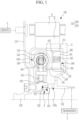
- FIG. 1 is a cross-sectional view made by cutting a hybrid driving module according to an embodiment of the present invention in an axial direction
- FIG. 2 is an enlarged view of part A in FIG. 1 .
- FIG. 1 is a half-cross-sectional view for explaining an embodiment of the present invention and illustrates a hybrid driving module 100 according to the embodiment of the present invention.
- the hybrid driving module 100 serves to selectively transmit rotational power, which is transmitted from an engine 2 and a motor 6, to a transmission 4, and the hybrid driving module 100 is disposed between the engine 2 and the transmission 4.
- the motor 6 may be applied to a general electric vehicle and include a rotor R and a stator S, the motor 6 may perform both functions of a motor and a generator.
- the hybrid driving module 100 may include a drive plate 110, a pilot hub 120, a cover part 125, a torsion damper 140, a transmission hub 152, and a one-way clutch 160.
- pilot hub 120, the cover part 125, and the transmission hub 152 may be coupled to one another and define an internal chamber.
- the torsion damper 140 and the one-way clutch 160 may be disposed in the internal chamber formed as described above.
- the internal chamber may have an inlet port into which a working fluid is introduced, and an outlet port.
- the outlet port may be formed in the transmission hub 152, and the inlet port may be formed between the pilot hub 120 and the transmission hub. This configuration will be specifically described below.
- the drive plate 110 is connected to the engine 2, and rotational power of the engine 2 may be inputted to the drive plate 110.
- the pilot hub 120 is provided is provided radially inside the drive plate 110 and disposed at a rotation center.
- the pilot hub 120 is mounted on the drive plate 110 by bolting.
- one end of the cover part 125 may be rotationally fixed to the transmission hub 152, and the other end of the cover part 125 may be rotatably connected to the pilot hub 120.
- the cover part 125 may include a damper cover 130 positioned at a side of the torsion damper 140, and a clutch cover 150 positioned at a side of the one-way clutch 160.
- one end of the clutch cover 150 may be rotationally fixed to the transmission hub 152.
- one end of the damper cover 130 may be rotationally fixed to the other end of the clutch cover 150. Further, the other end of the damper cover 130 may be rotatably mounted on the pilot hub 120 at the side of the engine 2.
- a seal member 132 may be mounted on an inner peripheral surface of the damper cover 130 to seal the damper cover 130 and the pilot hub 120.
- the seal member 132 may be disposed between the pilot hub 120 and the damper cover 130 and prevent the working fluid from leaking to the outside.
- the torsion damper 140 is disposed at the side of the engine 2 and disposed in the damper cover 130 and the clutch cover 150 coupled to each other.
- the torsion damper 140 is fixed to the pilot hub 120 so that the torsion damper 140 rotates together with the pilot hub 120.
- the torsion damper 140 may include a torque input part rotationally fixed to the engine 2, and a torque output part configured to output rotational power.
- the torsion damper 140 serves to absorb a torsional force applied in a rotation direction of a shaft by rotational power of the engine 2 transmitted to the torque input part through the drive plate 110 and serves to attenuate vibration.
- the torsion damper 140 may include a damper drive plate 141, spring members 142, a first cover plate 143, and a second cover plate 144.
- the damper drive plate 141 is coupled to the pilot hub 120.
- the torque input part may be rotationally fixed to the pilot hub 120. That is, the torque input part of the torsion damper 140 may be the damper drive plate 141.
- the damper drive plate 141 may receive the torsional force and vibration applied in the rotation direction of the shaft by the rotational power of the engine 2.
- the plurality of spring members 142 is disposed in a circumferential direction based on the rotation center and elastically supported by the damper drive plate 141.
- the spring 32 may be configured as a compression coil spring.
- first cover plate 143 and the second cover plate 144 may be disposed to surround the spring member 142 and elastically support the spring member 142.
- first cover plate 143 and the second cover plate 144 may be disposed to face each other.
- first cover plate 143 may be the torque output part of the torsion damper 140.
- the driving power transmitted to the damper drive plate 141 may be transmitted to the first and second cover plates 143 and 144 through the spring 24.
- the spring member 142 may absorb vibration and impact in the rotation direction.
- the torsion damper 140 which is configured as described above, may be disposed in the damper cover 130 and disposed at the side of the engine 2 based on an axial direction.
- the torsion damper 140 may be coupled to the pilot hub 120 and efficiently absorb the torsional force and vibration applied in the rotation direction of the shaft by the rotational power of the engine 2.
- the torsion damper 140 may be lubricated by the working fluid introduced into the damper cover 130 and the clutch cover 150 coupled to each other, such that friction caused by contact between the components may be reduced, and a degree of fatigue of the spring member 142 may be reduced, which may improve overall durability.
- the rotor R may be fixed to the damper cover 130 or the clutch cover 150 by a fixing means mounted radially outside the damper cover 130 or the clutch cover 150.
- the fixing means includes a fixing ring 151 mounted on the clutch cover 150.
- the rotor R may be disposed radially outside the damper cover 130 and the clutch cover 150 assembled to each other.
- the rotor R is fixed by the fixing ring 151 in a state in which an inner peripheral surface of the rotor R is seated on outer peripheral surfaces of the damper cover 130 and the clutch cover 150.
- stator S is disposed radially outside the rotor R.
- the fixing ring 151 is mounted on the clutch cover 150.
- the present invention is not limited thereto.
- the fixing ring 151 may be mounted on the outer peripheral surface of the damper cover 130.
- the transmission hub 152 is rotatably connected to the pilot hub 120.
- An inner peripheral surface of the clutch cover 150 may be fixed to the transmission hub 152 by welding or the like.
- a bearing 8 is interposed between the pilot hub 120 and the transmission hub 152.
- one end of the bearing 8, which is directed toward the engine 2 in the axial direction, is supported in a first stepped groove 122 formed radially inward in an inner peripheral surface of the pilot hub 120.
- the other end of the bearing 8, which is directed toward the transmission 2 in the axial direction, may be supported in a second stepped groove 154 formed radially inward in an outer peripheral surface of the transmission hub 152.
- the bearing 8 may be disposed between the pilot hub 120 and the transmission hub 152, and the first and second stepped grooves 122 and 154 may prevent the bearing 8 from being withdrawn in the axial direction.
- the bearing 8 may stably support the transmission hub 152 so that the transmission hub 152 is rotatable relative to the pilot hub 120.
- the internal chamber may be fluidly connected to and communicate with the transmission 4 through the bearing 8.
- the one-way clutch 160 is disposed at the side of the transmission 4 and disposed in the damper cover 130 and the clutch cover 150 coupled to each other.
- the one-way clutch 160 is connected to torque output part of the torsion damper 140.
- the one-way clutch 160 may connect the drive plate 110 directly to the clutch cover 150 and selectively transmit the rotational power of the engine 2 to the transmission hub 152 through the clutch cover 150.
- the one-way clutch 160 may transmit the rotational power of the engine 2 to the transmission 4 when the engine 2 operates.
- the one-way clutch 160 may transmit the rotational power of the engine 2 to the transmission 4 from a time point at which the engine 2 begins to rotate at a rotational speed higher than a rotational speed of the motor 6.
- the one-way clutch 160 may transmit the rotational power of the motor 6 to the transmission 4 while freely rotating.
- the one-way clutch 160 which is configured as described above, may be configured as a one-way clutch.
- the one-way clutch 160 may include a drive carrier 162, an inner race 163, an outer race 164, and a clutch element 165.
- the drive carrier 162 may be rotationally fixed to the first cover plate 143 that is the torque output part of the torsion damper 140.
- the drive carrier 162 may be fixedly coupled to the torsion damper 140 by riveting.
- the inner race 163 may be coupled to an outer peripheral surface of the drive carrier 162.
- the inner race 163 may be fixedly coupled to the drive carrier 162 by a snap ring 167 mounted on the outer peripheral surface of the drive carrier 162.
- the outer race 164 may be disposed at a position spaced apart radially outward from the inner race 163.
- the outer race 164 may be coupled to the inner peripheral surface of the clutch cover 150.
- the outer race 164 may be disposed at the side of the transmission 4 based on the axial direction and fixed to the inner peripheral surface of the clutch cover 150.
- the clutch element 165 may be provided between the inner race 163 and the outer race 164.
- the clutch element 165 may support the outer race 164 so that the outer race 164 is rotatable in one direction relative to the inner race 160.
- the outer race 164 and the clutch element 165 may be fixed to the inner peripheral surface of the clutch cover 150 by a retainer 166 coupled to the clutch cover 150.
- the retainer 166 may support and fix the outer race 164 and two opposite axial sides of the clutch element 165 together with the clutch cover 150.
- the retainer 166 may be fixed to the clutch cover 150 by the snap ring 167 mounted on the inner peripheral surface of the clutch cover 150.
- the inner race 163 may transmit the rotational power of the engine 2 to the transmission 4 through the transmission hub 152 while rotating together with the outer race 164 in the same direction as the outer race 164.
- the outer race 164 of the one-way clutch 160 may transmit the rotational power of the motor 6 to the transmission 4 while being rotated freely relative to the inner race 163 by the clutch element 165.
- the one-way clutch 160 may transmit the rotational power of the engine 2 directly to the transmission 4 from a time point at which the engine 2 begins to rotate at a rotational speed higher than a rotational speed of the motor while the inner race 163 and the outer race 164 are rotated together in the same direction by the clutch element 165.
- the working fluid passes through the bearing 8 between the pilot hub 120 and the transmission hub 152, flows in the internal chamber defined by the damper cover 130 and the clutch cover 150 coupled to each other, and then circulates to the transmission 4 through an outlet port 152a formed in the transmission hub 152.
- the working fluid in the internal chamber may flow to the bearing 8 from the internal chamber as internal pressure is adjusted.
- the working fluid which is introduced into the internal chamber defined by the damper cover 130 and the clutch cover 150, is supplied to the torsion damper 140 and the one-way clutch 160, flows through the bearing 8 while lubricating the torsion damper 140 and cooling the one-way clutch 160, which may contribute to lubricating the bearing 8.
- the transmission hub 152 may be connected to the transmission 4 through a torque converter or a fluid coupler.
- the application of the hybrid driving module 100 according to the embodiment of the present invention configured as described above may change the structure of the one-way clutch 160, thereby simplifying the overall constituent elements and coupling structures and reducing the number of manufacturing processes and manufacturing costs.
- the one-way clutch 160 freely rotates (free-wheeling) in accordance with the operation conditions of the vehicle and transmits power of the motor 6 without applying a load to the engine 2, such that the hybrid driving module 100 may drive the vehicle and perform regenerative braking.
- the one-way clutch 160 operates in accordance with the rotational speed of the engine 2, such that a separate hydraulic line and actuator may be eliminated, which may improve a degree of design freedom. Further, heat generation may be minimized, and durability and operational controllability may be improved.
- the one-way clutch 160 and the torsion damper 140 are mounted together in the internal chamber defined by the damper cover 130 and the clutch cover 150 assembled to each other, which may optimize the arrangement of the torsion damper 140 connected to the one-way clutch 160 and reduce the overall outer diameter and overall axial length.
- the working fluid is supplied to the torsion damper 140 provided in the internal chamber, such that the torsion damper 140 may be lubricated, the performance and durability may be improved, and the overall marketability may be improved.
Landscapes
- Engineering & Computer Science (AREA)
- Mechanical Engineering (AREA)
- Chemical & Material Sciences (AREA)
- Combustion & Propulsion (AREA)
- Transportation (AREA)
- General Engineering & Computer Science (AREA)
- Hybrid Electric Vehicles (AREA)
- Arrangement Of Transmissions (AREA)
- Arrangement Or Mounting Of Propulsion Units For Vehicles (AREA)
Abstract
Description
- The present invention relates to a hybrid driving module, and more particularly, to a hybrid driving module configured to transmit rotational power, which is inputted from an internal combustion engine and a motor to a transmission.
- An environmentally-friendly technology of vehicles is a key technology of the future vehicle industry, and vehicle manufacturers have made a great effort to develop environmentally-friendly vehicles in order to meet regulations associated with the environment and fuel economy.
- Examples of the future vehicle technology may include an electric vehicle (EV) using electrical energy, a hybrid electric vehicle (HEV), and a double-clutch transmission (DCT) with improved efficiency and convenience.
- The hybrid electric vehicle is a vehicle using two or more power sources, and the two or more power sources may be combined in various ways. Typically, a gasoline or diesel engine using the existing fossil fuel and a motor/generator operated by electrical energy are combined (hybrid).
- The hybrid electric vehicle is equipped with both an internal combustion engine and a motor, which may innovatively reduce the amount of emission of harmful gas and fuel consumption in comparison with general vehicles.
- Regarding the hybrid electric vehicle, there has been a need to develop a driving module equipped with an engine clutch and a torque converter which are capable of implementing effective power transmission and reducing the size and the number of components in order to effectively transmit rotational power from the engine and the motor to the transmission, improve the efficiency, and maximize fuel economy.
- Therefore, research and development are being consistently conducted on a hybrid driving module modularized together with a motor of a hybrid electric vehicle (HEV) while including functions of an engine clutch and a torque converter in order to efficiently combine and transmit driving power of an engine and the motor in the hybrid electric vehicle.
- The above information disclosed in this Background section is only for enhancement of understanding of the background of the invention and therefore it may contain information that does not form the prior art that is already known in this country to a person of ordinary skill in the art.
- Accordingly, the present invention has been made in an effort to solve the above-mentioned problem, and an object of the present invention is to provide a hybrid driving module, in which a structure of an engine clutch may be changed, all constituent elements and coupling structures may be simplified to reduce manufacturing costs, the hybrid driving module may operate in accordance with a rotational speed of the engine, and a separate hydraulic line and an actuator may be excluded.
- Another object of the present invention is to provide a hybrid driving module, in which an engine clutch and a torsion damper are mounted together in the interior into which a working fluid is introduced, such that the arrangement of the torsion damper connected to the engine clutch may be optimized, and an overall outer diameter and an overall axial length may be reduced.
- In order to achieve the above-mentioned objects, a hybrid driving module according to an embodiment of the present invention is configured to selectively transmit rotational power, which is transmitted from an engine and a motor, to a transmission and includes an internal chamber including an inlet port and an outlet port for a working fluid, a torsion damper including a torque input part rotationally fixed to the engine, and a torque output part, and a one-way clutch connected to the torque output part, in which the torsion damper and the one-way clutch are disposed in the internal chamber.
- In one embodiment of the present invention, the hybrid driving module may include: a pilot hub rotationally fixed to the engine; a transmission hub rotationally fixed to the transmission; and a cover part rotationally fixed to the transmission hub, in which the torque input part is rotationally fixed to the pilot hub, and in which the pilot hub, the transmission hub, and the cover part define the internal chamber.
- In another embodiment of the present invention, the one-way clutch may include: a drive carrier rotationally fixed to the torque output part of the torsion damper; an inner race coupled to the drive carrier; an outer race coupled to an inner peripheral surface of the cover part; and a clutch element provided between the inner race and the outer race and configured to support the outer race so that the outer race is rotatable in one direction relative to the inner race.
- In another embodiment of the present invention, the outer race and the clutch element may be fixed to the cover part by a retainer coupled to the cover part.
- In another embodiment of the present invention, the torque input part may include a damper drive plate having a radially inner side rotationally fixed to the pilot hub, the torque output part may include a cover plate rotationally fixed to the drive carrier, the torsion damper may be disposed radially outside the damper drive plate and include a plurality of spring members elastically supported in a circumferential direction by the damper drive plate, and the cover plate may be elastically supported in the circumferential direction by the spring members.
- In another embodiment of the present invention, one end of the cover part may be rotationally fixed to the transmission hub, and the other end of the cover part may be rotatably connected to the pilot hub.
- In another embodiment of the present invention, a seal member may be mounted between the other end of the cover part and the pilot hub.
- In another embodiment of the present invention, a bearing may be interposed between the clutch hub and the transmission hub, and the internal chamber may fluidly communicate with the transmission through the bearing.
- In another embodiment of the present invention, a rotor of the motor may be mounted radially outside the cover part.
- In another embodiment of the present invention, when the engine operates, the one-way clutch may transmit the rotational power of the engine to the transmission from a time point at which the engine begins to rotate at a rotational speed higher than a rotational speed of the motor.
- A hybrid driving module according to an embodiment of the present invention is configured to selectively transmit rotational power, which is transmitted from an engine and a motor, to a transmission and includes: a torsion damper configured to attenuate vibration caused by a rotation of the engine; and a one-way clutch configured to selectively transmit an output of the torsion damper to the transmission, in which a working fluid supplied from the transmission is used to lubricate the torsion damper.
- In one embodiment of the present invention, when only the motor operates, the one-way clutch may transmit the rotational power of the motor to the transmission while freely rotating, and when the engine operates, the one-way clutch may transmit the rotational power of the engine to the transmission from a time point at which the engine begins to rotate at a rotational speed higher than a rotational speed of the motor.
- According to the hybrid driving module according to the embodiment of the present invention described above, it is possible to change the structure of the engine clutch, thereby simplifying the overall constituent elements and coupling structures and reducing the number of manufacturing processes and manufacturing costs.
- In addition, according to the present invention, the engine clutch may freely rotate (free-wheeling) in accordance with the operation conditions of the vehicle and transmit power of the motor without applying a load to the engine, such that the hybrid driving module may drive the vehicle and perform regenerative braking.
- In addition, according to the present invention, the engine clutch operates in accordance with the rotational speed of the engine, such that a separate hydraulic line and actuator may be eliminated, which may improve a degree of design freedom. Further, heat generation may be minimized, and durability and operational controllability may be improved.
- In addition, according to the present invention, the engine clutch and the torsion damper are mounted together in the interior into which the working fluid is introduced, such that the arrangement of the torsion damper connected to the engine clutch may be optimized, and the overall outer diameter and the overall axial length may be reduced.
- Further, according to the present invention, the working fluid is supplied to the torsion damper, such that the torsion damper may be lubricated, the performance and durability may be improved, and the overall marketability may be improved.
-
-
FIG. 1 is a cross-sectional view made by cutting a hybrid driving module according to an embodiment of the present invention in an axial direction. -
FIG. 2 is an enlarged view of part A inFIG. 1 . - Hereinafter, exemplary embodiments of the present invention will be described in detail with reference to the accompanying drawings.
- The present invention is not limited to the embodiments disclosed herein, but will be variously changed and implemented in various different forms. The embodiments are provided so that the present invention will be thorough and complete, and also to provide a more complete understanding of the scope of the present invention to those of ordinary skill in the art.
- Therefore, it should be understood that the present invention is not limited to the embodiments disclosed below, but the configuration of any one embodiment and the configuration of another embodiment can be substituted or added, and the present invention includes all alterations, equivalents, and alternatives that are included in the technical spirit and scope of the present invention.
- In addition, it should be interpreted that the accompanying drawings are provided only to allow those skilled in the art to easily understand the embodiments disclosed in the present specification, and the technical spirit disclosed in the present specification is not limited by the accompanying drawings, and includes all alterations, equivalents, and alternatives that are included in the spirit and the technical scope of the present invention.
- A part irrelevant to the description will be omitted to clearly describe the present invention, and the same or similar constituent elements will be designated by the same reference numerals throughout the specification.
- The size and thickness of each component illustrated in the drawings are arbitrarily shown for ease of description, but the present invention is not necessarily limited thereto. In order to clearly describe several portions and regions, thicknesses thereof are enlarged.
- In the drawings, sizes or thicknesses of constituent elements may be exaggerated, increased, or decreased for convenience of understanding, but the protection scope of the present invention should not be restrictively construed.
- The terms used in the present specification are used only for the purpose of describing particular examples or embodiments and are not intended to limit the present invention. Further, singular expressions include plural expressions unless clearly described as different meanings in the context.
- In the present application, the terms "comprises," "comprising," "includes," "including," "containing," "has," "having", and other variations thereof are inclusive and therefore specify the presence of features, integers, steps, operations, elements, components, and/or combinations thereof disclosed in the specification. That is, in the present application, the terms "comprises," "comprising," "includes," "including," "containing," "has," "having", and other variations thereof need to be understood as not precluding the presence or addition of one or more other features, integers, steps, operations, elements, components, and/or combinations thereof.
- The terms including ordinal numbers such as "first," "second," and the like may be used to describe various constituent elements, but the constituent elements are not limited by the terms. These terms are used only to distinguish one constituent element from another constituent element.
- When one constituent element is described as being "coupled" or "connected" to another constituent element, it should be understood that one constituent element can be coupled or connected directly to another constituent element, and an intervening constituent element can also be present between the constituent elements.
- When one constituent element is described as being "coupled directly to" or "connected directly to" another constituent element, it should be understood that no intervening constituent element is present between the constituent elements.
- When one constituent element is described as being "disposed above" or "disposed below" another constituent element, it should be understood that one constituent element can be disposed directly on another constituent element, and an intervening constituent element can also be present between the constituent elements.
- Unless otherwise defined, all terms used herein, including technical or scientific terms, have the same meaning as commonly understood by those skilled in the art to which the present invention pertains.
- The terms such as those defined in a commonly used dictionary should be interpreted as having meanings consistent with meanings in the context of related technologies and should not be interpreted as ideal or excessively formal meanings unless explicitly defined in the present application.
- For the convenience, the directions in the specification are defined as follows.
- A forward/rearward direction or an axial direction is defined as a direction parallel to a rotation axis. A front (forward) means any one direction of a power source, e.g., a direction toward an engine. A rear (rearward) means the other direction, e.g., a direction toward a transmission. Therefore, a front surface means a surface facing forward, and a rear surface means a surface facing rearward.
- A radial direction means a direction toward or away from a center of the rotation axis along a straight line passing through the center of the rotation axis on the plane perpendicular to the rotation axis. A direction radially away from the center is referred to as a centrifugal direction, and a direction toward the center is referred to as a centripetal direction.
- A circumferential direction means a direction surrounding a circumference of the rotation axis. An outer periphery means an outer circumference, and an inner periphery means an inner circumference. Therefore, an outer peripheral surface is a surface facing away from the rotation axis, and an inner peripheral surface is a surface facing the rotation axis.
- A circumferential surface means a surface, a normal line of which is directed in an approximately circumferential direction.
- In addition, the term "unit", "means", "part", "member", or the like, which is described in the specification, means a unit of a comprehensive configuration that performs at least one function or operation.
-
FIG. 1 is a cross-sectional view made by cutting a hybrid driving module according to an embodiment of the present invention in an axial direction, andFIG. 2 is an enlarged view of part A inFIG. 1 . -
FIG. 1 is a half-cross-sectional view for explaining an embodiment of the present invention and illustrates ahybrid driving module 100 according to the embodiment of the present invention. - With reference to
FIG. 1 , thehybrid driving module 100 according to the embodiment of the present invention serves to selectively transmit rotational power, which is transmitted from anengine 2 and a motor 6, to a transmission 4, and thehybrid driving module 100 is disposed between theengine 2 and the transmission 4. - The motor 6 may be applied to a general electric vehicle and include a rotor R and a stator S, the motor 6 may perform both functions of a motor and a generator.
- In this case, the
hybrid driving module 100 according to the embodiment of the present invention may include adrive plate 110, apilot hub 120, acover part 125, atorsion damper 140, atransmission hub 152, and a one-way clutch 160. - In this case, the
pilot hub 120, thecover part 125, and thetransmission hub 152 may be coupled to one another and define an internal chamber. Thetorsion damper 140 and the one-way clutch 160 may be disposed in the internal chamber formed as described above. - The internal chamber may have an inlet port into which a working fluid is introduced, and an outlet port. In the present embodiment, the outlet port may be formed in the
transmission hub 152, and the inlet port may be formed between thepilot hub 120 and the transmission hub. This configuration will be specifically described below. - First, the
drive plate 110 is connected to theengine 2, and rotational power of theengine 2 may be inputted to thedrive plate 110. - The
pilot hub 120 is provided is provided radially inside thedrive plate 110 and disposed at a rotation center. Thepilot hub 120 is mounted on thedrive plate 110 by bolting. - In the present embodiment, one end of the
cover part 125 may be rotationally fixed to thetransmission hub 152, and the other end of thecover part 125 may be rotatably connected to thepilot hub 120. - In the illustrated embodiment, the
cover part 125 may include adamper cover 130 positioned at a side of thetorsion damper 140, and aclutch cover 150 positioned at a side of the one-way clutch 160. - In this case, one end of the
clutch cover 150 may be rotationally fixed to thetransmission hub 152. - In addition, one end of the
damper cover 130 may be rotationally fixed to the other end of theclutch cover 150. Further, the other end of thedamper cover 130 may be rotatably mounted on thepilot hub 120 at the side of theengine 2. - In this case, a
seal member 132 may be mounted on an inner peripheral surface of thedamper cover 130 to seal thedamper cover 130 and thepilot hub 120. - The
seal member 132 may be disposed between thepilot hub 120 and thedamper cover 130 and prevent the working fluid from leaking to the outside. - Meanwhile, the
torsion damper 140 is disposed at the side of theengine 2 and disposed in thedamper cover 130 and theclutch cover 150 coupled to each other. Thetorsion damper 140 is fixed to thepilot hub 120 so that thetorsion damper 140 rotates together with thepilot hub 120. - In this case, the
torsion damper 140 may include a torque input part rotationally fixed to theengine 2, and a torque output part configured to output rotational power. - The
torsion damper 140 serves to absorb a torsional force applied in a rotation direction of a shaft by rotational power of theengine 2 transmitted to the torque input part through thedrive plate 110 and serves to attenuate vibration. - In this case, the
torsion damper 140 may include adamper drive plate 141,spring members 142, afirst cover plate 143, and asecond cover plate 144. - First, the
damper drive plate 141 is coupled to thepilot hub 120. The torque input part may be rotationally fixed to thepilot hub 120. That is, the torque input part of thetorsion damper 140 may be thedamper drive plate 141. - Therefore, the
damper drive plate 141 may receive the torsional force and vibration applied in the rotation direction of the shaft by the rotational power of theengine 2. - The plurality of
spring members 142 is disposed in a circumferential direction based on the rotation center and elastically supported by thedamper drive plate 141. The spring 32 may be configured as a compression coil spring. - In the present embodiment, the
first cover plate 143 and thesecond cover plate 144 may be disposed to surround thespring member 142 and elastically support thespring member 142. - In this case, the
first cover plate 143 and thesecond cover plate 144 may be disposed to face each other. In addition, thefirst cover plate 143 may be the torque output part of thetorsion damper 140. - That is, the driving power transmitted to the
damper drive plate 141 may be transmitted to the first andsecond cover plates spring member 142 may absorb vibration and impact in the rotation direction. - The
torsion damper 140, which is configured as described above, may be disposed in thedamper cover 130 and disposed at the side of theengine 2 based on an axial direction. Thetorsion damper 140 may be coupled to thepilot hub 120 and efficiently absorb the torsional force and vibration applied in the rotation direction of the shaft by the rotational power of theengine 2. - The
torsion damper 140 may be lubricated by the working fluid introduced into thedamper cover 130 and theclutch cover 150 coupled to each other, such that friction caused by contact between the components may be reduced, and a degree of fatigue of thespring member 142 may be reduced, which may improve overall durability. - Meanwhile, the rotor R may be fixed to the
damper cover 130 or theclutch cover 150 by a fixing means mounted radially outside thedamper cover 130 or theclutch cover 150. In the embodiment of the present invention, the fixing means includes a fixingring 151 mounted on theclutch cover 150. - Therefore, the rotor R may be disposed radially outside the
damper cover 130 and theclutch cover 150 assembled to each other. The rotor R is fixed by the fixingring 151 in a state in which an inner peripheral surface of the rotor R is seated on outer peripheral surfaces of thedamper cover 130 and theclutch cover 150. - In this case, the stator S is disposed radially outside the rotor R.
- Meanwhile, in the present embodiment, one embodiment is described in which the
fixing ring 151 is mounted on theclutch cover 150. However, the present invention is not limited thereto. The fixingring 151 may be mounted on the outer peripheral surface of thedamper cover 130. - In the present embodiment, the
transmission hub 152 is rotatably connected to thepilot hub 120. An inner peripheral surface of theclutch cover 150 may be fixed to thetransmission hub 152 by welding or the like. - Meanwhile, with reference to
FIG. 1 , abearing 8 is interposed between thepilot hub 120 and thetransmission hub 152. - In this case, one end of the
bearing 8, which is directed toward theengine 2 in the axial direction, is supported in a first steppedgroove 122 formed radially inward in an inner peripheral surface of thepilot hub 120. - The other end of the
bearing 8, which is directed toward thetransmission 2 in the axial direction, may be supported in a second steppedgroove 154 formed radially inward in an outer peripheral surface of thetransmission hub 152. - Therefore, the
bearing 8 may be disposed between thepilot hub 120 and thetransmission hub 152, and the first and second steppedgrooves bearing 8 from being withdrawn in the axial direction. Thebearing 8 may stably support thetransmission hub 152 so that thetransmission hub 152 is rotatable relative to thepilot hub 120. - In addition, the internal chamber may be fluidly connected to and communicate with the transmission 4 through the
bearing 8. - In the present embodiment, as illustrated in
FIGS. 1 to 2 , the one-way clutch 160 is disposed at the side of the transmission 4 and disposed in thedamper cover 130 and theclutch cover 150 coupled to each other. The one-way clutch 160 is connected to torque output part of thetorsion damper 140. - The one-way clutch 160 may connect the
drive plate 110 directly to theclutch cover 150 and selectively transmit the rotational power of theengine 2 to thetransmission hub 152 through theclutch cover 150. - The one-way clutch 160 may transmit the rotational power of the
engine 2 to the transmission 4 when theengine 2 operates. - In this case, when the
engine 2 operates, the one-way clutch 160 may transmit the rotational power of theengine 2 to the transmission 4 from a time point at which theengine 2 begins to rotate at a rotational speed higher than a rotational speed of the motor 6. - In addition, when only the motor 6 operates, the one-way clutch 160 may transmit the rotational power of the motor 6 to the transmission 4 while freely rotating. The one-
way clutch 160, which is configured as described above, may be configured as a one-way clutch. - In the embodiment of the present invention, the one-way clutch 160 may include a
drive carrier 162, aninner race 163, anouter race 164, and aclutch element 165. - First, the
drive carrier 162 may be rotationally fixed to thefirst cover plate 143 that is the torque output part of thetorsion damper 140. In this case, thedrive carrier 162 may be fixedly coupled to thetorsion damper 140 by riveting. - The
inner race 163 may be coupled to an outer peripheral surface of thedrive carrier 162. - In this case, the
inner race 163 may be fixedly coupled to thedrive carrier 162 by asnap ring 167 mounted on the outer peripheral surface of thedrive carrier 162. - In the present embodiment, the
outer race 164 may be disposed at a position spaced apart radially outward from theinner race 163. Theouter race 164 may be coupled to the inner peripheral surface of theclutch cover 150. - That is, the
outer race 164 may be disposed at the side of the transmission 4 based on the axial direction and fixed to the inner peripheral surface of theclutch cover 150. - Further, the
clutch element 165 may be provided between theinner race 163 and theouter race 164. Theclutch element 165 may support theouter race 164 so that theouter race 164 is rotatable in one direction relative to theinner race 160. - In this case, the
outer race 164 and theclutch element 165 may be fixed to the inner peripheral surface of theclutch cover 150 by aretainer 166 coupled to theclutch cover 150. - That is, the
retainer 166 may support and fix theouter race 164 and two opposite axial sides of theclutch element 165 together with theclutch cover 150. Theretainer 166 may be fixed to theclutch cover 150 by thesnap ring 167 mounted on the inner peripheral surface of theclutch cover 150. - In the one-way clutch 160 configured as described above, when the rotational power of the
engine 2 is transmitted by thedrive carrier 162, theinner race 163 may transmit the rotational power of theengine 2 to the transmission 4 through thetransmission hub 152 while rotating together with theouter race 164 in the same direction as theouter race 164. - That is, when only the motor operates, the
outer race 164 of the one-way clutch 160 may transmit the rotational power of the motor 6 to the transmission 4 while being rotated freely relative to theinner race 163 by theclutch element 165. - In contrast, when the
engine 2 operates, the one-way clutch 160 may transmit the rotational power of theengine 2 directly to the transmission 4 from a time point at which theengine 2 begins to rotate at a rotational speed higher than a rotational speed of the motor while theinner race 163 and theouter race 164 are rotated together in the same direction by theclutch element 165. - Meanwhile, in the
hybrid driving module 100 according to the embodiment of the present invention, the working fluid passes through thebearing 8 between thepilot hub 120 and thetransmission hub 152, flows in the internal chamber defined by thedamper cover 130 and theclutch cover 150 coupled to each other, and then circulates to the transmission 4 through anoutlet port 152a formed in thetransmission hub 152. - In addition, the working fluid in the internal chamber may flow to the
bearing 8 from the internal chamber as internal pressure is adjusted. - That is, the working fluid, which is introduced into the internal chamber defined by the
damper cover 130 and theclutch cover 150, is supplied to thetorsion damper 140 and the one-way clutch 160, flows through thebearing 8 while lubricating thetorsion damper 140 and cooling the one-way clutch 160, which may contribute to lubricating thebearing 8. - Meanwhile, although not illustrated in the drawings, the
transmission hub 152 may be connected to the transmission 4 through a torque converter or a fluid coupler. - Therefore, the application of the
hybrid driving module 100 according to the embodiment of the present invention configured as described above may change the structure of the one-way clutch 160, thereby simplifying the overall constituent elements and coupling structures and reducing the number of manufacturing processes and manufacturing costs. - In addition, according to the
hybrid driving module 100, the one-way clutch 160 freely rotates (free-wheeling) in accordance with the operation conditions of the vehicle and transmits power of the motor 6 without applying a load to theengine 2, such that thehybrid driving module 100 may drive the vehicle and perform regenerative braking. - In addition, according to the present invention, the one-
way clutch 160 operates in accordance with the rotational speed of theengine 2, such that a separate hydraulic line and actuator may be eliminated, which may improve a degree of design freedom. Further, heat generation may be minimized, and durability and operational controllability may be improved. - In addition, according to the present invention, the one-
way clutch 160 and thetorsion damper 140 are mounted together in the internal chamber defined by thedamper cover 130 and theclutch cover 150 assembled to each other, which may optimize the arrangement of thetorsion damper 140 connected to the one-way clutch 160 and reduce the overall outer diameter and overall axial length. - In addition, according to the present invention, the working fluid is supplied to the
torsion damper 140 provided in the internal chamber, such that thetorsion damper 140 may be lubricated, the performance and durability may be improved, and the overall marketability may be improved. - The present invention has been described with reference to the limited exemplary embodiments and the drawings, but the present invention is not limited thereto. The described exemplary embodiments may be variously changed or modified by those skilled in the art to which the present invention pertains within the technical spirit of the present invention and within the scope equivalent to the appended claims.
- Further, even though the operational effects of the configurations of the present invention have not been explicitly disclosed and described in the description of the embodiment of the present invention, the effects, which can be expected by the corresponding configurations, should, of course, be acceptable.
Claims (12)
- A hybrid driving module, which is configured to selectively transmit rotational power, which is transmitted from an engine and a motor, to a transmission, the hybrid driving module comprising:an internal chamber including an inlet port and an outlet port for a working fluid;a torsion damper including a torque input part rotationally fixed to the engine, and a torque output part; anda one-way clutch connected to the torque output part,wherein the torsion damper and the one-way clutch are disposed in the internal chamber.
- The hybrid driving module of claim 1, comprising:a pilot hub rotationally fixed to the engine;a transmission hub rotationally fixed to the transmission; anda cover part rotationally fixed to the transmission hub,wherein the torque input part is rotationally fixed to the pilot hub, andwherein the pilot hub, the transmission hub, and the cover part define the internal chamber.
- The hybrid driving module of claim 2, wherein the one-way clutch comprises:a drive carrier rotationally fixed to the torque output part of the torsion damper;an inner race coupled to the drive carrier;an outer race coupled to an inner peripheral surface of the cover part; anda clutch element provided between the inner race and the outer race and configured to support the outer race so that the outer race is rotatable in one direction relative to the inner race.
- The hybrid driving module of claim 3, wherein the outer race and the clutch element are fixed to the cover part by a retainer coupled to the cover part.
- The hybrid driving module of claim 3, wherein the torque input part comprises a damper drive plate having a radially inner side rotationally fixed to the pilot hub,wherein the torque output part comprises a cover plate rotationally fixed to the drive carrier,wherein the torsion damper is disposed radially outside the damper drive plate and comprises a plurality of spring members elastically supported in a circumferential direction by the damper drive plate, andwherein the cover plate is elastically supported in the circumferential direction by the spring members.
- The hybrid driving module of claim 2, wherein one end of the cover part is rotationally fixed to the transmission hub, and the other end of the cover part is rotatably connected to the pilot hub.
- The hybrid driving module of claim 6, wherein a seal member is mounted between the other end of the cover part and the pilot hub.
- The hybrid driving module of claim 2, wherein a bearing is interposed between the pilot hub and the transmission hub, and the internal chamber fluidly communicates with the transmission through the bearing.
- The hybrid driving module of claim 2, wherein a rotor of the motor is mounted radially outside the cover part.
- The hybrid driving module of claim 1, wherein when the engine operates, the one-way clutch transmits the rotational power of the engine to the transmission from a time point at which the engine begins to rotate at a rotational speed higher than a rotational speed of the motor.
- A hybrid driving module, which is configured to selectively transmit rotational power, which is transmitted from an engine and a motor, to a transmission, the hybrid driving module comprising:a torsion damper configured to attenuate vibration caused by a rotation of the engine; anda one-way clutch configured to selectively transmit an output of the torsion damper to the transmission,wherein a working fluid supplied from the transmission is used to lubricate the torsion damper.
- The hybrid driving module of claim 11, wherein when only the motor operates, the engine clutch transmits the rotational power of the motor to the transmission while freely rotating, and
wherein when the engine operates, the engine clutch transmits the rotational power of the engine to the transmission from a time point at which the engine begins to rotate at a rotational speed higher than a rotational speed of the motor.
Applications Claiming Priority (2)
| Application Number | Priority Date | Filing Date | Title |
|---|---|---|---|
| KR1020210144505A KR102655262B1 (en) | 2021-10-27 | 2021-10-27 | Hybrid drive module |
| PCT/KR2022/015892 WO2023075272A1 (en) | 2021-10-27 | 2022-10-18 | Hybrid drive module |
Publications (2)
| Publication Number | Publication Date |
|---|---|
| EP4406764A1 true EP4406764A1 (en) | 2024-07-31 |
| EP4406764A4 EP4406764A4 (en) | 2025-09-10 |
Family
ID=86159479
Family Applications (1)
| Application Number | Title | Priority Date | Filing Date |
|---|---|---|---|
| EP22887468.1A Pending EP4406764A4 (en) | 2021-10-27 | 2022-10-18 | HYBRID DRIVE MODULE |
Country Status (6)
| Country | Link |
|---|---|
| US (1) | US20240408954A1 (en) |
| EP (1) | EP4406764A4 (en) |
| JP (1) | JP7837408B2 (en) |
| KR (1) | KR102655262B1 (en) |
| CN (1) | CN118159437A (en) |
| WO (1) | WO2023075272A1 (en) |
Cited By (1)
| Publication number | Priority date | Publication date | Assignee | Title |
|---|---|---|---|---|
| EP4737166A1 (en) * | 2024-11-04 | 2026-05-06 | Deere & Company | A controlled engine assist system |
Families Citing this family (2)
| Publication number | Priority date | Publication date | Assignee | Title |
|---|---|---|---|---|
| DE102021115521B3 (en) * | 2021-06-16 | 2022-09-29 | Schaeffler Technologies AG & Co. KG | Torque transfer device and drive train for a motor vehicle |
| KR102950206B1 (en) * | 2023-08-14 | 2026-04-21 | 주식회사 카펙발레오 | Hybrid power transfer module |
Family Cites Families (14)
| Publication number | Priority date | Publication date | Assignee | Title |
|---|---|---|---|---|
| US5931271A (en) * | 1997-09-19 | 1999-08-03 | General Motors Corporation | Hybrid drive with one-way drive connections |
| JP4069777B2 (en) * | 2002-04-03 | 2008-04-02 | アイシン・エィ・ダブリュ株式会社 | Hybrid vehicle drive system |
| WO2004053350A1 (en) * | 2002-12-10 | 2004-06-24 | Singapore Technologies Kinetics Ltd | A hybrid driving device and clutch/damper mechanism therefor and methods relating thereto |
| CN100434299C (en) * | 2004-04-28 | 2008-11-19 | 爱信艾达株式会社 | Drive unit for hybrid vehicles |
| KR20100077485A (en) * | 2008-12-29 | 2010-07-08 | 한국파워트레인 주식회사 | Torque converter for a vehicle |
| US8056663B2 (en) * | 2009-06-12 | 2011-11-15 | GM Global Technology Operations LLC | Hybrid module for interconnecting an engine and a dual-clutch transmission |
| JP5607954B2 (en) * | 2010-03-04 | 2014-10-15 | 本田技研工業株式会社 | Power transmission device for hybrid vehicle |
| JP2017106573A (en) * | 2015-12-10 | 2017-06-15 | アイシン・エィ・ダブリュ株式会社 | Power transmission device |
| JP6852338B2 (en) | 2016-09-30 | 2021-03-31 | アイシン精機株式会社 | Drive power generator |
| US20190072165A1 (en) * | 2017-09-06 | 2019-03-07 | Valeo Embrayages | Torsional vibration damper with multi-piece radially elastic output member, and method for making the same |
| US10792991B2 (en) * | 2018-12-05 | 2020-10-06 | Schaeffler Technologies AG & Co. KG | Hybrid module including torque converter having a stator friction brake |
| US10808822B1 (en) | 2019-05-10 | 2020-10-20 | Valeo Kapec Co., Ltd. | Hydrokinetic torque-coupling device having lock-up clutch with dual piston assembly and selectable one-way clutch |
| US11407302B2 (en) * | 2020-02-26 | 2022-08-09 | Borgwarner Inc. | Torque transfer assembly and vehicle including the same |
| KR102315995B1 (en) * | 2020-04-06 | 2021-10-21 | 현대트랜시스 주식회사 | Torsional damper for vehicle |
-
2021
- 2021-10-27 KR KR1020210144505A patent/KR102655262B1/en active Active
-
2022
- 2022-10-18 US US18/702,682 patent/US20240408954A1/en active Pending
- 2022-10-18 JP JP2024525543A patent/JP7837408B2/en active Active
- 2022-10-18 EP EP22887468.1A patent/EP4406764A4/en active Pending
- 2022-10-18 WO PCT/KR2022/015892 patent/WO2023075272A1/en not_active Ceased
- 2022-10-18 CN CN202280071901.2A patent/CN118159437A/en active Pending
Cited By (1)
| Publication number | Priority date | Publication date | Assignee | Title |
|---|---|---|---|---|
| EP4737166A1 (en) * | 2024-11-04 | 2026-05-06 | Deere & Company | A controlled engine assist system |
Also Published As
| Publication number | Publication date |
|---|---|
| KR20230060584A (en) | 2023-05-08 |
| EP4406764A4 (en) | 2025-09-10 |
| KR102655262B1 (en) | 2024-04-19 |
| US20240408954A1 (en) | 2024-12-12 |
| CN118159437A (en) | 2024-06-07 |
| JP7837408B2 (en) | 2026-03-30 |
| JP2024540146A (en) | 2024-10-31 |
| WO2023075272A1 (en) | 2023-05-04 |
Similar Documents
| Publication | Publication Date | Title |
|---|---|---|
| US20240408954A1 (en) | Hybrid drive module | |
| EP4040016B1 (en) | Hybrid drive module | |
| CN102007012B (en) | Vehicle drive device | |
| CN102574454B (en) | Drive device for vehicle | |
| US12187128B2 (en) | Power transmission apparatus for hybrid vehicle | |
| US9636990B2 (en) | Hybrid drive apparatus | |
| US12240328B2 (en) | P2 module architecture | |
| US12576706B2 (en) | Compact P2 hybrid architecture | |
| US11919401B2 (en) | Compact P2 hybrid architecture | |
| WO2020243041A1 (en) | Integrated torque converter and p2 module | |
| US11376942B2 (en) | Torque converter with sealed turbine shell and clutch cooling | |
| EP4230454B1 (en) | Hybrid drive module | |
| KR102291313B1 (en) | Hybrid drive module and manufacturing method of rotor provided in this | |
| US11285798B2 (en) | Drive system | |
| KR102616855B1 (en) | Hybrid drive module | |
| KR20230034730A (en) | Hybrid drive module | |
| JP2024002104A (en) | power transmission device | |
| CN119489676A (en) | Hybrid Transmission Module |
Legal Events
| Date | Code | Title | Description |
|---|---|---|---|
| STAA | Information on the status of an ep patent application or granted ep patent |
Free format text: STATUS: THE INTERNATIONAL PUBLICATION HAS BEEN MADE |
|
| PUAI | Public reference made under article 153(3) epc to a published international application that has entered the european phase |
Free format text: ORIGINAL CODE: 0009012 |
|
| STAA | Information on the status of an ep patent application or granted ep patent |
Free format text: STATUS: REQUEST FOR EXAMINATION WAS MADE |
|
| 17P | Request for examination filed |
Effective date: 20240426 |
|
| AK | Designated contracting states |
Kind code of ref document: A1 Designated state(s): AL AT BE BG CH CY CZ DE DK EE ES FI FR GB GR HR HU IE IS IT LI LT LU LV MC ME MK MT NL NO PL PT RO RS SE SI SK SM TR |
|
| DAV | Request for validation of the european patent (deleted) | ||
| DAX | Request for extension of the european patent (deleted) | ||
| A4 | Supplementary search report drawn up and despatched |
Effective date: 20250811 |
|
| RIC1 | Information provided on ipc code assigned before grant |
Ipc: B60K 6/383 20071001AFI20250805BHEP Ipc: B60K 6/24 20071001ALI20250805BHEP Ipc: B60K 6/36 20071001ALI20250805BHEP Ipc: F16D 41/00 20060101ALI20250805BHEP Ipc: F16D 13/70 20060101ALI20250805BHEP Ipc: F16D 23/06 20060101ALI20250805BHEP Ipc: B60K 6/48 20071001ALI20250805BHEP |