EP4406674A1 - Housing and manufacturing method therefor, and terminal device - Google Patents
Housing and manufacturing method therefor, and terminal device Download PDFInfo
- Publication number
- EP4406674A1 EP4406674A1 EP23829665.1A EP23829665A EP4406674A1 EP 4406674 A1 EP4406674 A1 EP 4406674A1 EP 23829665 A EP23829665 A EP 23829665A EP 4406674 A1 EP4406674 A1 EP 4406674A1
- Authority
- EP
- European Patent Office
- Prior art keywords
- wall
- housing
- corner
- groove
- side wall
- Prior art date
- Legal status (The legal status is an assumption and is not a legal conclusion. Google has not performed a legal analysis and makes no representation as to the accuracy of the status listed.)
- Granted
Links
Images





Classifications
-
- B—PERFORMING OPERATIONS; TRANSPORTING
- B21—MECHANICAL METAL-WORKING WITHOUT ESSENTIALLY REMOVING MATERIAL; PUNCHING METAL
- B21D—WORKING OR PROCESSING OF SHEET METAL OR METAL TUBES, RODS OR PROFILES WITHOUT ESSENTIALLY REMOVING MATERIAL; PUNCHING METAL
- B21D35/00—Combined processes according to or processes combined with methods covered by groups B21D1/00 - B21D31/00
- B21D35/002—Processes combined with methods covered by groups B21D1/00 - B21D31/00
-
- B—PERFORMING OPERATIONS; TRANSPORTING
- B21—MECHANICAL METAL-WORKING WITHOUT ESSENTIALLY REMOVING MATERIAL; PUNCHING METAL
- B21D—WORKING OR PROCESSING OF SHEET METAL OR METAL TUBES, RODS OR PROFILES WITHOUT ESSENTIALLY REMOVING MATERIAL; PUNCHING METAL
- B21D22/00—Shaping without cutting, by stamping, spinning, or deep-drawing
-
- B—PERFORMING OPERATIONS; TRANSPORTING
- B21—MECHANICAL METAL-WORKING WITHOUT ESSENTIALLY REMOVING MATERIAL; PUNCHING METAL
- B21D—WORKING OR PROCESSING OF SHEET METAL OR METAL TUBES, RODS OR PROFILES WITHOUT ESSENTIALLY REMOVING MATERIAL; PUNCHING METAL
- B21D24/00—Special deep-drawing arrangements in, or in connection with, presses
- B21D24/16—Additional equipment in association with the tools, e.g. for shearing, for trimming
-
- G—PHYSICS
- G06—COMPUTING OR CALCULATING; COUNTING
- G06F—ELECTRIC DIGITAL DATA PROCESSING
- G06F1/00—Details not covered by groups G06F3/00 - G06F13/00 and G06F21/00
- G06F1/16—Constructional details or arrangements
- G06F1/1613—Constructional details or arrangements for portable computers
- G06F1/1615—Constructional details or arrangements for portable computers with several enclosures having relative motions, each enclosure supporting at least one I/O or computing function
-
- G—PHYSICS
- G06—COMPUTING OR CALCULATING; COUNTING
- G06F—ELECTRIC DIGITAL DATA PROCESSING
- G06F1/00—Details not covered by groups G06F3/00 - G06F13/00 and G06F21/00
- G06F1/16—Constructional details or arrangements
- G06F1/1613—Constructional details or arrangements for portable computers
- G06F1/1615—Constructional details or arrangements for portable computers with several enclosures having relative motions, each enclosure supporting at least one I/O or computing function
- G06F1/1616—Constructional details or arrangements for portable computers with several enclosures having relative motions, each enclosure supporting at least one I/O or computing function with folding flat displays, e.g. laptop computers or notebooks having a clamshell configuration, with body parts pivoting to an open position around an axis parallel to the plane they define in closed position
-
- G—PHYSICS
- G06—COMPUTING OR CALCULATING; COUNTING
- G06F—ELECTRIC DIGITAL DATA PROCESSING
- G06F1/00—Details not covered by groups G06F3/00 - G06F13/00 and G06F21/00
- G06F1/16—Constructional details or arrangements
- G06F1/1613—Constructional details or arrangements for portable computers
- G06F1/1626—Constructional details or arrangements for portable computers with a single-body enclosure integrating a flat display, e.g. Personal Digital Assistants [PDAs]
-
- G—PHYSICS
- G06—COMPUTING OR CALCULATING; COUNTING
- G06F—ELECTRIC DIGITAL DATA PROCESSING
- G06F1/00—Details not covered by groups G06F3/00 - G06F13/00 and G06F21/00
- G06F1/16—Constructional details or arrangements
- G06F1/1613—Constructional details or arrangements for portable computers
- G06F1/1633—Constructional details or arrangements of portable computers not specific to the type of enclosures covered by groups G06F1/1615 - G06F1/1626
- G06F1/1656—Details related to functional adaptations of the enclosure, e.g. to provide protection against EMI, shock, water, or to host detachable peripherals like a mouse or removable expansions units like PCMCIA cards, or to provide access to internal components for maintenance or to removable storage supports like CDs or DVDs, or to mechanically mount accessories
-
- Y—GENERAL TAGGING OF NEW TECHNOLOGICAL DEVELOPMENTS; GENERAL TAGGING OF CROSS-SECTIONAL TECHNOLOGIES SPANNING OVER SEVERAL SECTIONS OF THE IPC; TECHNICAL SUBJECTS COVERED BY FORMER USPC CROSS-REFERENCE ART COLLECTIONS [XRACs] AND DIGESTS
- Y02—TECHNOLOGIES OR APPLICATIONS FOR MITIGATION OR ADAPTATION AGAINST CLIMATE CHANGE
- Y02E—REDUCTION OF GREENHOUSE GAS [GHG] EMISSIONS, RELATED TO ENERGY GENERATION, TRANSMISSION OR DISTRIBUTION
- Y02E60/00—Enabling technologies; Technologies with a potential or indirect contribution to GHG emissions mitigation
- Y02E60/10—Energy storage using batteries
Definitions
- This application relates to the field of terminal device technologies, and in particular, to a housing, a manufacturing method therefor, and a terminal device.
- a terminal device such as a notebook computer, a mobile phone, or a tablet computer has become an important tool for daily working and entertainment of people.
- a housing of the terminal device is an important component thereof, and how to design and manufacture the housing becomes an important issue in the industry.
- a housing of a terminal device is formed by bending a sheet material in a pressure machining manner, and at a corner of the housing, a rounded corner is usually formed by bending.
- a rounded corner is too large, appearance and refinement of the housing may be affected. Therefore, to reduce a size of the rounded corner, after the housing is formed, a material around the rounded corner is milled through numerical control machining.
- time consumed for adding a procedure of the numerical control machining is long, lowering production efficiency of the housing.
- Embodiments of this application provide a housing, a manufacturing method therefor, and a terminal device, to resolve a problem of low production efficiency of the housing of the terminal device in related technologies.
- an embodiment of this application provides a housing, including a bottom wall and a side wall bent and connected to an edge of the bottom wall, where a part of the side wall away from the bottom wall is bent inward to form an inner bent wall, and a part of the side wall located between the inner bent wall and the bottom wall is a vertical wall; and a first corner formed by the inner bent wall and the vertical wall is provided with a first structural portion formed by pressure machining, so that plastic deformation occurs at a first rounded corner located on an outer side of the first corner, to reduce a radius of the first rounded corner.
- the radius of the first rounded corner can be reduced by replacing time-consuming numerical control milling machining with pressure machining. In this way, manufacturing time of the housing can be shortened, to improve manufacturing efficiency of the housing, and a texture trace of a milling cutter is also prevented from being left on an appearance surface of the housing.
- the first structural portion includes a first groove, and the first groove is arranged on an inner side of the first corner and extends in a circumferential direction of the housing.
- the first groove is arranged at a junction between the vertical wall and the inner bent wall.
- the first groove can be closer to the first rounded corner, so that the first groove is more easily formed.
- a wall thickness of the vertical wall is d1
- the first structural portion includes a first extrusion surface, and the first extrusion surface is located on an outer side of the inner bent wall and is connected to the first rounded corner.
- a second corner formed by the side wall and the bottom wall is provided with a second structural portion formed by pressure machining, so that plastic deformation occurs at a second rounded corner located on an outer side of the second corner, to reduce a radius of the second rounded corner.
- manufacturing time of the housing can be shortened, to improve manufacturing efficiency of the housing, and the texture trace of the milling cutter is also prevented from being left on the appearance surface of the housing.
- the second structural portion includes a second groove, and the second groove is arranged on an inner side of the second corner and extends in the circumferential direction of the housing.
- the second groove is arranged at a junction between the bottom wall and the side wall.
- the second groove can be closer to the second rounded corner, so that the second groove is more easily formed.
- the second structural portion includes a second extrusion surface, and the second extrusion surface is located at an end portion of the side wall away from the bottom wall.
- wall thicknesses of the bottom wall, the vertical wall, and the inner bent wall are equal.
- the vertical wall is provided with an opening, and the inner bent wall is arranged at the opening in the circumferential direction of the housing.
- an embodiment of this application provides a terminal device, including the housing according to the first aspect.
- an embodiment of this application provides a manufacturing method for a housing, including: bending an edge area of a sheet material to form a side wall of the housing, where a center area of the sheet material forms a bottom wall of the housing; bending a part of the side wall away from the bottom wall inward to form an inner bent wall, where a part of the side wall located between the inner bent wall and the bottom wall is a vertical wall; and performing pressure machining on a first corner formed by the inner bent wall and the vertical wall, so that plastic deformation occurs at a first rounded corner located on an outer side of the first corner, to reduce a radius of the first rounded corner.
- the performing pressure machining on a first corner includes: extruding an inner side of the first corner, to form a first groove extending in a circumferential direction of the housing.
- the method further includes: extruding, during the bending a part of the side wall away from the bottom wall inward, the inner side of the first corner to form the first groove.
- the performing pressure machining on a first corner further includes: clamping the vertical wall after the first groove is formed, to prevent plastic deformation of the vertical wall in a thickness direction; stamping or extruding the inner bent wall in a direction close to the bottom wall, to reduce the radius of the first rounded corner; and forming a first extrusion surface on an outer side of the inner bent wall.
- the inner bent wall is subjected to extrusion force and undergoes plastic deformation in the direction close to the bottom wall, and part of a material on the outer side of the inner bent wall is extruded to the first rounded corner, so that the radius of the first rounded corner is further reduced.
- a wrinkle on the vertical wall caused by plastic deformation of the vertical wall under pressure can be avoided.
- the method further includes: performing pressure machining on a second corner formed by the side wall and the bottom wall, so that plastic deformation occurs at a second rounded corner located on an outer side of the second corner, to reduce a radius of the second rounded corner.
- manufacturing time of the housing can be shortened, to improve manufacturing efficiency of the housing, and a texture trace of a milling cutter is also prevented from being left on an appearance surface of the housing.
- the performing pressure machining on a second corner includes: extruding an inner side of the second corner, to form a second groove extending in the circumferential direction of the housing.
- the performing pressure machining on a second corner further includes: clamping the side wall after the second groove is formed, to prevent plastic deformation of the side wall in the thickness direction; stamping or extruding an end portion of the side wall away from the bottom wall in the direction close to the bottom wall, to reduce the radius of the second rounded corner; and forming a second extrusion surface at the end portion of the side wall away from the bottom wall.
- part of a material on the side wall is extruded to the second rounded corner, so that the radius of the second rounded corner is further reduced.
- a wrinkle on the side wall caused by plastic deformation of the side wall under pressure can be avoided.
- the bending an edge area of a sheet material to form a side wall of the housing, and the extruding an inner side of the second corner, to form a second groove extending in the circumferential direction of the housing include: bending the edge area of the sheet material inward at a preset angle to form the side wall, and extruding the inner side of the second corner to form a transition groove, where the preset angle is less than 90°; and continuously bending the side wall inward to a preset position, and extruding a position of the transition groove, to form the second groove.
- this design can avoid forming a wrinkle on an outer side surface of the second corner due to overlarge plastic deformation at the second corner, thereby ensuring flatness of appearance at the second corner.
- the preset angle ranges from 45° to 70°.
- plastic deformation at the second corner can be small when the side wall is bent each time, thereby ensuring flatness of the outer side surface of the second corner.
- first and second are used merely for description of an objective, and cannot be understood as indicating or implying relative importance or implicitly indicating a quantity of indicated technical features. Therefore, features limited by “first” and “second” may explicitly or implicitly include one or more of the features.
- a terminal device in embodiments of this application may be a mobile phone, a tablet computer, a notebook computer, a wearable device (such as a smart watch), or the like.
- a specific structure and a manufacturing method of a housing of the terminal device are described below by using the notebook computer and the tablet computer as examples, and another terminal device may be set by specifically referring to the housing and the manufacturing method therefor in embodiments of the notebook computer and the tablet computer. Details are not described herein again.
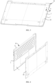
- FIG. 1 is a schematic diagram of a structure of a notebook computer according to some embodiments of this application.
- a terminal device is a notebook computer
- the notebook computer includes a display screen 200 and a host body 100.
- the display screen 200 is rotatably connected to the host body 100, so that the display screen 200 and the host body 100 may be switched between a folded state and an open state (a state shown in FIG. 1 ).
- a specific angle between a display surface of the display screen 200 and the host body 100 such as 90° or 120°.
- the display surface of the display screen 200 is stacked with the host body 100, in other words, the display surface of the display screen 200 is parallel to or approximately parallel to the host body 100 (for example, a deviation is within 5°).
- the display screen 200 and the host body 100 may be hinged through a hinge shaft, or may be hinged through a hinge structure. This is not specifically limited herein.
- the display screen 200 is detachably connected to the host body 100.
- the display screen 200 may be placed on the host body 100, and after use, the display screen 200 may be separated from the host body 100, so that the notebook computer is more convenient to carry and use.
- FIG. 2 is a schematic diagram of a structure of a front surface of the host body 100 in FIG. 1
- FIG. 3 is a schematic diagram of a structure of a back surface of the host body 100 in FIG. 1
- FIG. 4 is an exploded view of the host body 100 in FIG. 1 after internal electronic components are disassembled.
- the host body 100 includes a housing 10 (also referred to as a "cover C component") and a back cover 20.
- a keyboard 710 and a touch panel 720 are mounted on a side of the housing 10 (as shown in FIG. 1 ).
- the back cover 20 is detachably buckled on a back side of the housing 10, so that the back cover 20 and the housing 10 enclose an accommodating space, and the accommodating space is for arranging the internal electronic components of the notebook computer.
- the back cover 20 may be detachably connected to the housing 10 through fasteners such as screws (as shown in FIG. 3 ), or may be detachably connected to the housing 10 through snapping. This is not specifically limited herein.
- FIG. 5 is a sectional view of a host body 100 of a notebook computer at an edge in related technologies.
- a housing 10 includes a bottom wall 1 and a side wall 2 bent and connected to an edge of the bottom wall 1, an angle between the side wall 2 and the bottom wall 1 is approximately perpendicular, and a back cover 20 is detachably buckled on a back side of the housing 10, and is connected to the side wall 2.
- a seam between the back cover 20 and the side wall 2 is too close to an appearance surface of the housing 10 (an outer side surface of the side wall 2), and when the notebook computer is flatly placed on an edge of a table, a user may easily observe the seam from a lower side of the notebook computer, affecting appearance and refinement of the notebook computer.
- FIG. 6 is a sectional view of a host body 100 of another notebook computer at an edge in the related technologies
- FIG. 7 is a schematic diagram of removing, through numerical control machining, a material of a housing 10 of the notebook computer in FIG. 6 after being formed.
- the housing 10 includes a bottom wall 1 and a side wall 2 bent and connected to an edge of the bottom wall 1, where a part of the side wall 2 away from the bottom wall 1 is bent inward to form an inner bent wall 21.
- a back cover 20 is detachably buckled on a back side of the housing 10, and is connected to the inner bent wall 21.
- a first rounded corner 23 exists at a bending position of the inner bent wall 21, and if a radius of the first rounded corner 23 is too large, appearance and refinement of the housing 10 are affected.
- the first rounded corner 23 is located on the side wall 2 of the housing 10, it is not easy to make the first rounded corner 23 smaller in a bending process of the side wall 2, and in a general bending forming process (for example, forming through stamping and bending), the radius of the first rounded corner 23 is once or more a wall thickness of the side wall 2.
- a material around the first rounded corner 23 is milled through numerical control milling machining (as shown in FIG. 7 , a dotted line part in the figure is a contour of the side wall 2 before the material is removed, and a solid line part is a contour of the side wall 2 after the material is removed.
- the thickness of the side wall 2 (including the inner bent wall 21) is milled thin, and in this case, the wall thickness of the side wall 2 is less than a wall thickness of the bottom wall 1), to reduce the radius of the first rounded corner 23.
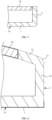
- FIG. 8 is a three-dimensional sectional view of the host body 100 in FIG. 3 along A-A.
- the housing 10 includes a bottom wall 1 and a side wall 2 bent and connected to an edge of the bottom wall 1, where a part of the side wall 2 away from the bottom wall 1 is bent inward to form an inner bent wall 21, and a part of the side wall 2 located between the inner bent wall 21 and the bottom wall 1 is a vertical wall 22.
- a first corner 24 formed by the inner bent wall 21 and the vertical wall 22 is provided with a first structural portion 25 formed by pressure machining, so that plastic deformation occurs at a first rounded corner 23 located on an outer side of the first corner 24, to reduce a radius of the first rounded corner 23.
- the first corner 24 specifically refers to an area with a specific angle formed by the inner bent wall 21 and the vertical wall 22, and the area includes the inner bent wall 21, a transition area in which the inner bent wall 21 is connected to the vertical wall 22, and a partial area of the vertical wall 22 close to the inner bent wall 21.
- the first structural portion 25 formed by pressure machining By arranging the first structural portion 25 formed by pressure machining, plastic deformation can occur at the first rounded corner 23, to reduce the radius of the first rounded corner 23. In this way, the radius of the first rounded corner 23 can be reduced by replacing time-consuming numerical control milling machining with pressure machining. In this way, manufacturing time of the housing 10 can be shortened, to improve manufacturing efficiency of the housing 10, and a texture trace of a milling cutter is also prevented from being left on an appearance surface of the housing 10.
- a material of the housing 10 may be made of metal or alloy prone to plastic deformation, such as aluminum, aluminum alloy, or steel (such as stainless steel).
- the angle formed between the inner bent wall 21 and the vertical wall 22 may be an obtuse angle (as shown in FIG. 8 ) or a right angle. This may be specifically determined according to an actual condition.
- the first structural portion 25 includes a first groove 251, and the first groove 251 is arranged on an inner side of the first corner 24 and extends in a circumferential direction of the housing 10.
- the first groove 251 is formed, a material at the first groove 251 is extruded from an inner side of the side wall 2 to the first rounded corner 23, to reduce the radius of the first rounded corner 23.
- Arrangement of the first groove 251 merely enables local plastic deformation to occur at the first corner 24, so that impact on structural integrity and structural strength of the side wall 2 is small.
- the first groove 251 is arranged at a junction between the vertical wall 22 and the inner bent wall 21.
- the first groove 251 can be closer to the first rounded corner 23, and when the first groove 251 is formed, the material at the first groove 251 is more easily extruded to the first rounded corner 23, so that the first groove 251 is more easily formed.
- the first groove 251 may also be arranged on an inner side surface of the vertical wall 22 or the inner bent wall 21. This is not specifically limited herein.
- a groove depth of the first groove 251 is h1, representing an important parameter of the housing 10.
- d1 is a wall thickness of the vertical wall 22.
- the groove depth h1 of the first groove 251 should be set to be 0.1 to 0.15 mm, so that the strength at the first corner 24 can be ensured, and the reduction of the first rounded corner 23 can also be prevented from being too small.
- the first structural portion 25 further includes a first extrusion surface 252, and the first extrusion surface 252 is located on an outer side of the inner bent wall 21 and is connected to the first rounded corner 23.
- the inner bent wall 21 is subjected to extrusion force and undergoes plastic deformation in a direction close to the bottom wall 1, and part of a material on the outer side of the inner bent wall 21 is extruded to the first rounded corner 23, so that the radius of the first rounded corner 23 is further reduced.
- a wall thickness of the side wall 2 is 0.8 mm (in other words, the thickness of the vertical wall 22 and a thickness of the inner bent wall 21 are both 0.8 mm).
- the radius of the first rounded corner 23 can be reduced to 0.8 mm; and by arranging the first extrusion surface 252, the radius of the first rounded corner 23 can be further reduced to 0.3 mm on a basis of 0.8 mm.
- the first extrusion surface 252 may be formed by stamping (for example, pier extrusion), but is not limited thereto, or the first extrusion surface 252 may be formed by extrusion. This is not specifically limited.
- pier extrusion belongs to a stamping method
- a pier extrusion forming mold is a male mold (also referred to as a convex mold) and a female mold (also referred to as a concave mold).
- Extrusion is a processing method in which a blank is placed in an extrusion mold cavity, and under the room temperature, pressure is applied to the blank through a convex mold fixed on a press, so that the blank undergoes plastic deformation to obtain a part.
- the foregoing first structural portion 25 may include both the first groove 251 and the first extrusion surface 252, and may also include only one of the first groove 251 and the first extrusion surface 252, so that the radius of the first rounded corner 23 can be reduced.
- FIG. 9 is a sectional view of an edge of the host body 100 in FIG. 3 according to other embodiments.
- a second corner 3 formed by the side wall 2 and the bottom wall 1 is provided with a second structural portion 4 formed by pressure machining, so that plastic deformation occurs at a second rounded corner 5 located on an outer side of the second corner 3, to reduce a radius of the second rounded corner 5.
- the second corner 3 specifically refers to an area with a specific angle formed by the side wall 2 and the bottom wall 1, and the area includes a side wall 2, a transition area in which the side wall 2 is connected to the bottom wall 1, and a partial area of the bottom wall 1 close to the side wall 2.
- the second structural portion 4 includes a second groove 41, and the second groove 41 is arranged on an inner side of the second corner 3 and extends in the circumferential direction of the housing 10.
- the second groove 41 is formed, a material at the second groove 41 is extruded from an inner side of the second corner 3 to a position of the second rounded corner 5, to reduce the radius of the second rounded corner 5.
- Arrangement of the second groove 41 merely enables local plastic deformation to occur at the second corner 3, so that impact on structural integrity and structural strength at an edge of the housing 10 is small.
- the second groove 41 is arranged at a junction between the bottom wall 1 and the side wall 2.
- the second groove 41 can be closer to the second rounded corner 5, and when the second groove 41 is formed, the material at the second groove 41 is more easily extruded to the second rounded corner 5, so that the second groove 41 is more easily formed.
- the second groove 41 may also be arranged on an inner side surface of the bottom wall 1 or the side wall 2. This is not specifically limited herein.
- a groove depth of the second groove 41 is h2, representing an important parameter of the housing 10.
- d2 is a wall thickness of the bottom wall 1.
- the groove depth h2 of the second groove 41 should be set to be 0.1 to 0.15 mm, so that the strength at the second corner 3 can be ensured, and the reduction of the second rounded corner 5 can also be prevented from being too small.
- the second structural portion 4 further includes a second extrusion surface 42, and the second extrusion surface 42 is located at an end portion of the side wall 2 away from the bottom wall 1.
- the second extrusion surface 42 is formed, the side wall 2 is subjected to extrusion force and undergoes plastic deformation in the direction close to the bottom wall 1, and part of a material of the side wall 2 is extruded to the second rounded corner 5, so that the radius of the second rounded corner 5 is further reduced.
- the wall thickness of the side wall 2 is 0.8 mm.
- the radius of the second rounded corner 5 can be reduced to 0.8 mm or less, such as 0.45 mm; and by arranging the second extrusion surface 42, the radius of the second rounded corner 5 can be further reduced, for example, can be reduced to 0 mm (in other words, the second rounded corner 5 is eliminated, and the junction between the bottom wall 1 and the side wall 2 is at a right angle).
- the second extrusion surface 42 may be formed by stamping (for example, back extrusion), but is not limited thereto, or the first extrusion surface 252 may be formed by extrusion. This is not specifically limited.
- the wall thicknesses of the bottom wall 1, the vertical wall 22, and the inner bent wall 21 are equal.
- the wall thicknesses of the bottom wall 1, the vertical wall 22, and the inner bent wall 21 are all 0.8 mm.
- the edge of the housing 10 namely, the side wall 2 can have enough strength, and large deformation at the edge of the housing 10 under the action of external force is avoided, thereby ensuring reliability of a structure of the housing 10.
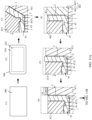
- FIG. 10A is a schematic diagram of a manufacturing process of the housing 10 shown in FIG. 8
- a bottom wall 1 and a side wall 2 shown in FIG. 10A are merely schematic diagrams, and are not shown according to a real proportion of actual products
- FIG. 10B is a flowchart of the manufacturing process of the housing 10 shown in FIG. 8 .
- the manufacturing method for a housing 10 includes the following steps: S1: As shown in (2) and (3) in FIG. 10A , bend an edge area 310 of a sheet material 300 to form a side wall 2 of the housing 10, where a central area 320 of the sheet material 300 forms a bottom wall 1 of the housing 10.
- the bending an edge area 310 of a sheet material 300 may be implemented through mold stamping: As shown in (3) in FIG. 10A , the sheet material 300 is placed at an opening of a mold cavity of a first concave mold 411, where a shape of the mold cavity of the first concave mold 411 matches a shape of a to-be-formed housing 10; a first convex mold 412 stamps the sheet material 300 into the mold cavity of the first concave mold 411; and under pressure of the first convex mold 412, the edge area 310 of the sheet material 300 is bent to form the side wall 2 of the housing 10.
- the edge area 310 of the sheet material 300 may also be bent in a sheet metal machining manner, for example, the bending may be implemented on a plate bending machine.
- the sheet material 300 Before the bending an edge area 310 of a sheet material 300, the sheet material 300 needs to be preprocessed. For example, as shown in (1) in FIG. 10A , corners of the sheet material 300 are cut to form rounded corners.
- an end portion of the side wall 2 away from the bottom wall 1 also needs to be cut, so that a height of the side wall 2 is adjusted to a design requirement.
- the radius of the first rounded corner 23 can be reduced by replacing time-consuming numerical control milling machining with pressure machining. In this way, manufacturing time of the housing 10 can be shortened, to improve manufacturing efficiency of the housing 10, and a texture trace of a milling cutter is also prevented from being left on an appearance surface of the housing 10.
- the performing pressure machining on a first corner 24 in S2 includes: extruding an inner side of the first corner 24, to form a first groove 251 extending in a circumferential direction of the housing 10. Because arrangement of the first groove 251 merely enables local plastic deformation to occur at the first corner 24, impact on structural integrity and structural strength of the side wall 2 is small.
- the inner side of the first corner 24 is extruded to form the first groove 251.
- a process can be reduced, so that the manufacturing efficiency of the housing 10 is further improved.
- the bending a part of the side wall 2 away from the bottom wall 1 inward and the first groove 251 may be formed in the following manner: As shown in (5) in FIG. 10A , the housing 10 is arranged in a third concave mold 431, a first inner slider 432 is arranged in the housing 10, the first inner slider 432 is provided with a first pressure rib 4321, and a push slider 433 is arranged on an edge of the third concave mold 431.
- the push slider 433 By pushing the push slider 433 to an inner side of the side wall 2, the part of the side wall 2 away from the bottom wall 1 (in other words, a part of the side wall 2 extending out of the third concave mold 431) is bent inward to form the inner bent wall 21.
- the first inner slider 432 is pushed towards the vertical wall 22, so that the first pressure rib 4321 extrudes the inner side of the first corner 24, to form the first groove 251.
- the bending a part of the side wall 2 away from the bottom wall 1 inward and forming of the first groove 251 may be further designed as two separate processes. For example, first, the part of the side wall 2 away from the bottom wall 1 is bent inward to form the inner bent wall 21; and then the inner side of the first corner 24 is extruded, to form the first groove 251.
- the performing pressure machining on a first corner 24 in S2 further includes: clamping the vertical wall 22 after the first groove 251 is formed, to prevent plastic deformation of the vertical wall 22 in a thickness direction; stamping (for example, pier-extruding) or extruding the inner bent wall 21 in a direction close to the bottom wall 1, to reduce the radius of the first rounded corner 23; and forming a first extrusion surface 252 on an outer side of the inner bent wall 21.
- the inner bent wall 21 is subjected to extrusion force and undergoes plastic deformation in the direction close to the bottom wall 1, and part of a material on the outer side of the inner bent wall 21 is extruded to the first rounded corner 23, so that the radius of the first rounded corner 23 is further reduced.
- a wrinkle on the vertical wall 22 caused by plastic deformation of the vertical wall 22 under pressure can be avoided.
- the stamping or extruding the inner bent wall 21 may be implemented in the following manner: As shown in (6) in FIG. 10A , the housing 10 is arranged in a fourth concave mold 441, and the housing 10 is provided with a fourth convex mold 442.
- the fourth convex mold 442 and the fourth concave mold 441 clamp the vertical wall 22, and an extrusion block 443 stamps or extrudes the inner bent wall 21 in the direction close to the bottom wall 1, so that the inner bent wall 21 undergoes plastic deformation in the direction close to the bottom wall 1 until the inner bent wall 21 abuts against a surface of the fourth convex mold 442.
- the first extrusion surface 252 is formed through extruding the outer side of the inner bent wall 21.
- the first groove 251 plays a role in accommodating part of the material of the inner bent wall 21.
- the part of the material of the inner bent wall 21 flows to the first groove 251, to fill a part of space of the first groove 251, so that a width of the first groove 251 is reduced.
- FIG. 11A and FIG. 11B are a schematic diagram of a manufacturing process of the housing 10 shown in FIG. 9 .
- the method further includes: performing pressure machining on a second corner 3 formed by the side wall 2 and the bottom wall 1, so that plastic deformation occurs at a second rounded corner 5 located on an outer side of the second corner 3, to reduce a radius of the second rounded corner 5.
- the radius of the second rounded corner 5 is reduced without setting time-consuming numerical control milling machining.
- manufacturing time of the housing 10 can be shortened, to improve manufacturing efficiency of the housing 10, and the texture trace of the milling cutter is also prevented from being left on an appearance surface of the housing 10.
- the performing pressure machining on a second corner 3 includes: as shown in (3) to (5) in FIG. 11A , extruding an inner side of the second corner 3, to form a second groove 41 extending in the circumferential direction of the housing 10. Because arrangement of the second groove 41 merely enables local plastic deformation to occur at the second corner 3, impact on structural integrity and structural strength at the edge of the housing 10 is small.
- the bending an edge area 310 of a sheet material 300 to form a side wall 2 of the housing 10, and the extruding an inner side of the second corner 3, to form a second groove 41 extending in the circumferential direction of the housing 10 includes the following steps: S11: As shown in (2) and (3) in FIG. 11A , bend the edge area 310 of the sheet material 300 inward at a preset angle to form the side wall 2, and extrude the inner side of the second corner 3 to form a transition groove 43.
- the preset angle is less than 90°.
- the bending of the edge area 310 of the sheet material 300 and forming of the transition groove 43 may be implemented through mold stamping: As shown in (3) in FIG. 11A , the sheet material 300 is placed at an opening of a mold cavity of a fifth concave mold 451, where a shape of the mold cavity of the fifth concave mold 451 matches the shape of the to-be-formed housing 10 a fifth convex mold 453 stamps the sheet material 300 into the mold cavity of the fifth concave mold 451, where a second pressure rib 4531 is arranged on the fifth convex mold 453; and under pressure of the fifth convex mold 453, the edge area 310 of the sheet material 300 is bent to abut against the fifth convex mold 453, to bend at the preset angle.
- the second pressure rib 4531 extrudes the inner side of the second corner 3, to form the transition groove 43.
- the edge area 310 of the sheet material 300 may also be bent at the preset angle in a sheet metal machining manner, for example, the bending may be implemented on a plate bending machine.
- the sheet material 300 Before the bending an edge area 310 of a sheet material 300, the sheet material 300 needs to be preprocessed. For example, as shown in (1) in FIG. 11A , corners of the sheet material 300 are cut to form the rounded corners.
- the preset position may be a position at which the side wall 2 is perpendicular to or approximately perpendicular to the bottom wall 1 (a deviation is within 5°), or may be another position. This is not specifically limited herein.
- the continuously bending the side wall 2 inward to a second preset angle may be implemented in the following manner: As shown in (4) in FIG. 11A , the housing 10 with the side wall 2 being bent at the preset angle is arranged in a sixth concave mold 461, a concave mold side wall 4611 of the sixth concave mold 461 may slide relative to a concave mold bottom wall 4612, and a sixth convex mold 462 is arranged in the housing 10. Then, the concave mold side wall 4611 is slid towards the inner side of the side wall 2, to push to bend the side wall 2 until the side wall 2 abuts against the sixth convex mold 462, so that the side wall 2 is bent to the preset position.
- the bending the side wall 2 to the preset position is not limited to the foregoing manner, and the bending the side wall 2 to the preset position may also be implemented in the sheet metal machining manner, for example, the bending may be implemented on the plate bending machine.
- the second groove 41 may be implemented in the following manner: As shown in (5) in FIG. 11A , the housing 10 is arranged in a seventh concave mold 471, a third inner slider 472 is arranged in the housing 10, and a third pressure rib 4721 is arranged on the third inner slider 472. Next, the third inner slider 472 is pushed in the direction close to the bottom wall 1, so that the third pressure rib 4721 extrudes the transition groove 43, to form the second groove 41.
- the side wall 2 is bent twice to reach the preset position, and the second groove 41 is formed by extrusion twice.
- a wrinkle on an outer side surface of the second corner 3 can be avoided being formed due to overlarge plastic deformation at the second corner 3, thereby ensuring flatness of appearance at the second corner 3.
- the preset angle (namely, a first bending angle of the side wall 2) should not be too large or too small. If the preset angle is too large, plastic deformation at the second corner 3 is still large, not conducive to keeping flatness of the outer side surface of the second corner 3. If the preset angle is too small, a second bending angle of the side wall 2 is too large, and plastic deformation at the second corner 3 is also large, not conducive to keeping the flatness of the outer side surface of the second corner 3 as well. It is found through researches that, when the preset angle ranges from 45° to 70°, plastic deformation at the second corner 3 can be small when the side wall 2 is bent each time, thereby ensuring the flatness of the outer side surface of the second corner 3.
- the method further includes: clamping the side wall 2 after the second groove 41 is formed, to prevent plastic deformation of the side wall 2 in the thickness direction; stamping (for example, extruding back) or extruding the end portion of the side wall away 2 from the bottom wall 1 in the direction close to the bottom wall 1, to reduce the radius of the second rounded corner 5; and forming a second extrusion surface 42 at the end portion of the side wall 2 away from the bottom wall 1.
- the side wall 2 is subjected to extrusion force and undergoes plastic deformation in the direction close to the bottom wall 1, and part of a material of the side wall 2 is extruded to the second rounded corner 5, so that the radius of the second rounded corner 5 is further reduced.
- a wrinkle on the side wall 2 caused by plastic deformation of the side wall 2 under pressure can be avoided.
- the stamping or extruding the side wall 2 may be implemented in the following manner: As shown in (7) in FIG. 11B , the housing 10 is arranged in an eighth concave mold 481, and an eighth convex mold 482 is arranged in the housing 10.
- the eighth convex mold 482 and the eighth concave mold 481 clamp the side wall 2, and an extrusion block stamps or extrudes the end portion of the side wall 2 away from the bottom wall 1 in the direction close to the bottom wall 1, so that plastic deformation occurs at the side wall 2 in the direction close to the bottom wall 1, to reduce the radius of the second rounded corner 5.
- Processes of forming the inner bent wall 21 and a first structural portion 25 are shown in (8) and (9) in FIG. 11B , and are specifically the same as processes in (5) and (6) in FIG. 10A . Details are not described herein again.
- part of the side wall 2 is removed in the circumferential direction of the housing 10, to form an avoidance notch 8 for mounting a display screen 200.
- the avoidance notch 8 may be formed in a milling manner, or may be formed in a cutting manner. This is not specifically limited herein.
- the manufacturing method for a housing 10 further includes: performing grinding, sand blasting, anodic dyeing, and laser etching processing on the housing 10.
- first rounded corner 23 and the second rounded corner 5 may also be ground, so that the radiuses of the first rounded corner 23 and the second rounded corner 5 are smaller.
- Sand blasting is to clean and roughen a surface of the housing 10 through impacting of a high-speed sand flow, so that the surface of the housing 10 obtains cleanliness and different roughness, and a mechanical property of the surface of the housing 10 is improved, thereby enhancing fatigue resistance of the housing 10, increasing adhesion between the housing and a coating, and prolonging durability of the coating.
- Anodic dyeing (also referred to as electrochemical coloring) is to color a surface color of the housing 10, to be specific, perform anodic oxidation or coating on the surface of the housing 10, and then color, under an action of an electric field during electrolysis, an oxide film or the coating of the surface of the housing 10.
- Laser etching is based on a numerical control technology, with a laser as a processing medium, to inscribe a character or pattern on the housing 10.
- the pattern or character inscribed through this technology does not have a score, the surface of the housing 10 is still smooth, and the inscribed character or pattern is not abraded.
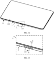
- FIG. 12 is a schematic diagram of a structure of a tablet computer according to some embodiments of this application
- FIG. 13 is a partial enlarged view of part A in FIG. 12
- FIG. 14 is a sectional view in FIG. 13 along B-B.
- a terminal device is a tablet computer
- the tablet computer includes a housing 10, a rubber frame 500, and a display panel 600.
- the rubber frame 500 is arranged in the housing 10 and a part of the rubber frame 500 extends out of the housing 10, a positioning step 510 is arranged on the rubber frame 500, and an edge of the display panel 600 is arranged on the positioning step 510.
- the display panel 600 may be fixed on the positioning step 510 by bonding, but is not limited thereto, or may be fixed on the positioning step 510 by snapping.
- the housing 10 includes a bottom wall 1 and a side wall 2 bent and connected to an edge of the bottom wall 1, where a part of the side wall 2 away from the bottom wall 1 is bent inward to form an inner bent wall 21.
- first structural portion 25 and a second structural portion 4 may be specifically referred to description in the embodiment of the notebook computer. Details are not described herein again.
- the housing 10 is provided with the first structural portion 25, where the first structural portion 25 includes a first groove 251 and a first extrusion surface 252, the first groove 251 is arranged on an inner side of a first corner 24 and extends in a circumferential direction of the housing 10, and the first extrusion surface 252 is located on an outer side of the inner bent wall 21 and is connected to a first rounded corner 23.
- an outer side of the first corner 24 formed by the inner bent wall 21 and a vertical wall 22 is provided with a chamfer 26, to cut off the first rounded corner 23.
- a contour before the first rounded corner 23 is cut off is shown in dotted lines in the figure.
- the vertical wall 22 is provided with an opening 221.
- the opening 221 may penetrate through the vertical wall 22, or may not penetrate through the vertical wall 22. This is not specifically limited herein.
- the opening 221 may be a sound outlet hole (as shown in FIG. 11A and FIG. 11B ), or may be a socket (such as a charging interface) for plugging a plug of an external device. This is not specifically limited herein. Because the opening 221 is arranged on the vertical wall 22, a structure of the housing 10 at the opening 221 is weak, strength and rigidity are low, and bending resistance is poor.
- the inner bent wall 21 is arranged at the opening 221 in the circumferential direction of the housing 10.
- strength of the housing 10 at the opening 221 is improved, thereby greatly improving rigidity and bending resistance of the housing 10.
- the housing 10 is made of a 5052-H32 aluminum alloy material
- thicknesses of the bottom wall 1 and the vertical wall 22 are 0.8 mm
- a thickness of the inner bent wall 21 is 0.65 mm
- a rigidity gain of the housing 10 is increased by 15% or more when the inner bent wall 21 is arranged at the opening 221.
- the inner bent wall 21 may be arranged in a partial area of the vertical wall 22, or may be arranged in all areas of the vertical wall 22. This is not specifically limited herein.
- the inner bent wall 21 in other areas of the vertical wall 22 may be milled by milling or the like.
- the rubber frame 500 is provided with an avoidance groove 520 for the inner bent wall 21 to extend into.
- a groove wall of the avoidance groove 520 has a limiting effect on deformation of the inner bent wall 21, thereby further improving the rigidity and bending resistance of the housing 10.
- a manufacturing method for a housing 10 in the tablet computer may be arranged by specifically referring to a manufacturing method for a housing 10 in the embodiment of the notebook computer. Details are not described herein again.
Landscapes
- Engineering & Computer Science (AREA)
- Theoretical Computer Science (AREA)
- Computer Hardware Design (AREA)
- Physics & Mathematics (AREA)
- General Engineering & Computer Science (AREA)
- Human Computer Interaction (AREA)
- General Physics & Mathematics (AREA)
- Mechanical Engineering (AREA)
- Mathematical Physics (AREA)
- Casings For Electric Apparatus (AREA)
- Manufacturing Of Electrical Connectors (AREA)
Abstract
Description
- This application claims priority to
Chinese Patent Application No. 202210764603.3, filed with the China National Intellectual Property Administration on June 30, 2022 - This application relates to the field of terminal device technologies, and in particular, to a housing, a manufacturing method therefor, and a terminal device.
- With improvement of living standards of people, a terminal device such as a notebook computer, a mobile phone, or a tablet computer has become an important tool for daily working and entertainment of people. A housing of the terminal device is an important component thereof, and how to design and manufacture the housing becomes an important issue in the industry.
- In related technologies, a housing of a terminal device is formed by bending a sheet material in a pressure machining manner, and at a corner of the housing, a rounded corner is usually formed by bending. When the rounded corner is too large, appearance and refinement of the housing may be affected. Therefore, to reduce a size of the rounded corner, after the housing is formed, a material around the rounded corner is milled through numerical control machining. However, time consumed for adding a procedure of the numerical control machining is long, lowering production efficiency of the housing.
- Embodiments of this application provide a housing, a manufacturing method therefor, and a terminal device, to resolve a problem of low production efficiency of the housing of the terminal device in related technologies.
- To achieve the foregoing objective, the following technical solutions are applied in embodiments of this application:
- According to a first aspect, an embodiment of this application provides a housing, including a bottom wall and a side wall bent and connected to an edge of the bottom wall, where a part of the side wall away from the bottom wall is bent inward to form an inner bent wall, and a part of the side wall located between the inner bent wall and the bottom wall is a vertical wall; and a first corner formed by the inner bent wall and the vertical wall is provided with a first structural portion formed by pressure machining, so that plastic deformation occurs at a first rounded corner located on an outer side of the first corner, to reduce a radius of the first rounded corner.
- By using the foregoing technical solution, the radius of the first rounded corner can be reduced by replacing time-consuming numerical control milling machining with pressure machining. In this way, manufacturing time of the housing can be shortened, to improve manufacturing efficiency of the housing, and a texture trace of a milling cutter is also prevented from being left on an appearance surface of the housing.
- In some embodiments, the first structural portion includes a first groove, and the first groove is arranged on an inner side of the first corner and extends in a circumferential direction of the housing.
- By using the foregoing technical solution, impact on structural integrity and structural strength of the side wall is small.
- In some embodiments, the first groove is arranged at a junction between the vertical wall and the inner bent wall.
- By using the foregoing technical solution, the first groove can be closer to the first rounded corner, so that the first groove is more easily formed.
- In some embodiments, a wall thickness of the vertical wall is d1, and a groove depth of the first groove is h1, where h1=(0.125 to 0.1875) d1.
- By using the foregoing technical solution, strength at the first corner can be ensured, and reduction of the first rounded corner can also be prevented from being too small.
- In some embodiments, the first structural portion includes a first extrusion surface, and the first extrusion surface is located on an outer side of the inner bent wall and is connected to the first rounded corner.
- By using the foregoing technical solution, when the first extrusion surface is formed, part of a material on the outer side of the inner bent wall is extruded to the first rounded corner, so that the radius of the first rounded corner is further reduced.
- In some embodiments, a second corner formed by the side wall and the bottom wall is provided with a second structural portion formed by pressure machining, so that plastic deformation occurs at a second rounded corner located on an outer side of the second corner, to reduce a radius of the second rounded corner.
- By using the foregoing technical solution, manufacturing time of the housing can be shortened, to improve manufacturing efficiency of the housing, and the texture trace of the milling cutter is also prevented from being left on the appearance surface of the housing.
- In some embodiments, the second structural portion includes a second groove, and the second groove is arranged on an inner side of the second corner and extends in the circumferential direction of the housing.
- By using the foregoing technical solution, impact on structural integrity and structural strength at an edge of the housing is small.
- In some embodiments, the second groove is arranged at a junction between the bottom wall and the side wall.
- By using the foregoing technical solution, the second groove can be closer to the second rounded corner, so that the second groove is more easily formed.
- In some embodiments, a wall thickness of the bottom wall is d2, and a groove depth of the second groove is h2, where h2=(0.125 to 0.1875) d2.
- By using the foregoing technical solution, strength at the second corner can be ensured, and reduction of the second rounded corner can also be prevented from being too small.
- In some embodiments, the second structural portion includes a second extrusion surface, and the second extrusion surface is located at an end portion of the side wall away from the bottom wall.
- By using the foregoing technical solution, when the second extrusion surface is formed, part of a material on the side wall is extruded to the second rounded corner, so that the radius of the second rounded corner is further reduced.
- In some embodiments, wall thicknesses of the bottom wall, the vertical wall, and the inner bent wall are equal.
- By using the foregoing technical solution, large deformation at an edge of the housing under an action of external force is avoided, thereby ensuring reliability of a structure of the housing.
- In some embodiments, the vertical wall is provided with an opening, and the inner bent wall is arranged at the opening in the circumferential direction of the housing.
- By using the foregoing technical solution, strength of the housing at the opening is enhanced, and rigidity and bending resistance of the housing are greatly improved.
- According to a second aspect, an embodiment of this application provides a terminal device, including the housing according to the first aspect.
- Technical effects obtained by the terminal device according to the second aspect and the housing according to the first aspect are the same. Details are not described herein again.
- According to a third aspect, an embodiment of this application provides a manufacturing method for a housing, including: bending an edge area of a sheet material to form a side wall of the housing, where a center area of the sheet material forms a bottom wall of the housing; bending a part of the side wall away from the bottom wall inward to form an inner bent wall, where a part of the side wall located between the inner bent wall and the bottom wall is a vertical wall; and performing pressure machining on a first corner formed by the inner bent wall and the vertical wall, so that plastic deformation occurs at a first rounded corner located on an outer side of the first corner, to reduce a radius of the first rounded corner.
- Technical effects obtained by the manufacturing method for a housing according to the third aspect and the housing according to the first aspect are the same. Details are not described herein again.
- In some embodiments, the performing pressure machining on a first corner includes: extruding an inner side of the first corner, to form a first groove extending in a circumferential direction of the housing.
- By using the foregoing technical solution, impact on structural integrity and structural strength of the side wall is small.
- In some embodiments, the method further includes: extruding, during the bending a part of the side wall away from the bottom wall inward, the inner side of the first corner to form the first groove.
- By using the foregoing technical solution, a process can be reduced, so that manufacturing efficiency of the housing is further improved.
- In some embodiments, the performing pressure machining on a first corner further includes: clamping the vertical wall after the first groove is formed, to prevent plastic deformation of the vertical wall in a thickness direction; stamping or extruding the inner bent wall in a direction close to the bottom wall, to reduce the radius of the first rounded corner; and forming a first extrusion surface on an outer side of the inner bent wall.
- By using the foregoing technical solution, the inner bent wall is subjected to extrusion force and undergoes plastic deformation in the direction close to the bottom wall, and part of a material on the outer side of the inner bent wall is extruded to the first rounded corner, so that the radius of the first rounded corner is further reduced. By clamping the vertical wall, a wrinkle on the vertical wall caused by plastic deformation of the vertical wall under pressure can be avoided.
- In some embodiments, after the bending an edge area of a sheet material to form a side wall of the housing, the method further includes: performing pressure machining on a second corner formed by the side wall and the bottom wall, so that plastic deformation occurs at a second rounded corner located on an outer side of the second corner, to reduce a radius of the second rounded corner.
- By using the foregoing technical solution, manufacturing time of the housing can be shortened, to improve manufacturing efficiency of the housing, and a texture trace of a milling cutter is also prevented from being left on an appearance surface of the housing.
- In some embodiments, the performing pressure machining on a second corner includes: extruding an inner side of the second corner, to form a second groove extending in the circumferential direction of the housing.
- By using the foregoing technical solution, impact on structural integrity and structural strength at an edge of the housing is small.
- In some embodiments, the performing pressure machining on a second corner further includes: clamping the side wall after the second groove is formed, to prevent plastic deformation of the side wall in the thickness direction; stamping or extruding an end portion of the side wall away from the bottom wall in the direction close to the bottom wall, to reduce the radius of the second rounded corner; and forming a second extrusion surface at the end portion of the side wall away from the bottom wall.
- By using the foregoing technical solution, part of a material on the side wall is extruded to the second rounded corner, so that the radius of the second rounded corner is further reduced. By clamping the side wall, a wrinkle on the side wall caused by plastic deformation of the side wall under pressure can be avoided.
- In some embodiments, the bending an edge area of a sheet material to form a side wall of the housing, and the extruding an inner side of the second corner, to form a second groove extending in the circumferential direction of the housing include: bending the edge area of the sheet material inward at a preset angle to form the side wall, and extruding the inner side of the second corner to form a transition groove, where the preset angle is less than 90°; and continuously bending the side wall inward to a preset position, and extruding a position of the transition groove, to form the second groove.
- By using the foregoing technical solution, this design can avoid forming a wrinkle on an outer side surface of the second corner due to overlarge plastic deformation at the second corner, thereby ensuring flatness of appearance at the second corner.
- In some embodiments, the preset angle ranges from 45° to 70°.
- By using the foregoing technical solution, plastic deformation at the second corner can be small when the side wall is bent each time, thereby ensuring flatness of the outer side surface of the second corner.
-
-
FIG. 1 is a schematic diagram of a structure of a notebook computer according to some embodiments of this application; -
FIG. 2 is a schematic diagram of a structure of a front surface of a host body inFIG. 1 ; -
FIG. 3 is a schematic diagram of a structure of a back surface of a host body inFIG. 1 ; -
FIG. 4 is an exploded view of a host body inFIG. 1 after internal electronic components are disassembled; -
FIG. 5 is a sectional view of a host body of a notebook computer at an edge in related technologies; -
FIG. 6 is a sectional view of a host body of another notebook computer at an edge in the related technologies; -
FIG. 7 is a schematic diagram of removing, through numerical control machining, a material of a housing of the notebook computer inFIG. 6 after being formed; -
FIG. 8 is a three-dimensional sectional view of the host body inFIG. 3 along A-A; -
FIG. 9 is sectional view of an edge of the host body inFIG. 3 according to other embodiments; -
FIG. 10A is a schematic diagram of a manufacturing process of a housing shown inFIG. 8 ; -
FIG. 10B is a flowchart of a manufacturing process of a housing shown inFIG. 8 ; -
FIG. 11A andFIG. 11B are a schematic diagram of a manufacturing process of a housing shown inFIG. 9 ; -
FIG. 12 is a schematic diagram of a structure of a tablet computer according to some embodiments of this application; -
FIG. 13 is a partial enlarged view of part A inFIG. 12 ; and -
FIG. 14 is a three-dimensional sectional view inFIG. 13 along B-B. - In embodiments of this application, terms "first" and "second" are used merely for description of an objective, and cannot be understood as indicating or implying relative importance or implicitly indicating a quantity of indicated technical features. Therefore, features limited by "first" and "second" may explicitly or implicitly include one or more of the features.
- A terminal device in embodiments of this application may be a mobile phone, a tablet computer, a notebook computer, a wearable device (such as a smart watch), or the like.
- A specific structure and a manufacturing method of a housing of the terminal device are described below by using the notebook computer and the tablet computer as examples, and another terminal device may be set by specifically referring to the housing and the manufacturing method therefor in embodiments of the notebook computer and the tablet computer. Details are not described herein again.
- As shown in
FIG. 1, FIG. 1 is a schematic diagram of a structure of a notebook computer according to some embodiments of this application. In the embodiments, a terminal device is a notebook computer, and the notebook computer includes adisplay screen 200 and ahost body 100. Thedisplay screen 200 is rotatably connected to thehost body 100, so that thedisplay screen 200 and thehost body 100 may be switched between a folded state and an open state (a state shown inFIG. 1 ). - When in the open state, there is a specific angle between a display surface of the
display screen 200 and thehost body 100, such as 90° or 120°. When in the folded state, the display surface of thedisplay screen 200 is stacked with thehost body 100, in other words, the display surface of thedisplay screen 200 is parallel to or approximately parallel to the host body 100 (for example, a deviation is within 5°). - The
display screen 200 and thehost body 100 may be hinged through a hinge shaft, or may be hinged through a hinge structure. This is not specifically limited herein. - In some embodiments, the
display screen 200 is detachably connected to thehost body 100. In this design, during use, thedisplay screen 200 may be placed on thehost body 100, and after use, thedisplay screen 200 may be separated from thehost body 100, so that the notebook computer is more convenient to carry and use. - As shown in
FIG. 2 ,FIG. 3, and FIG. 4 ,FIG. 2 is a schematic diagram of a structure of a front surface of thehost body 100 inFIG. 1 ,FIG. 3 is a schematic diagram of a structure of a back surface of thehost body 100 inFIG. 1 , andFIG. 4 is an exploded view of thehost body 100 inFIG. 1 after internal electronic components are disassembled. - The
host body 100 includes a housing 10 (also referred to as a "cover C component") and aback cover 20. Akeyboard 710 and atouch panel 720 are mounted on a side of the housing 10 (as shown inFIG. 1 ). - The
back cover 20 is detachably buckled on a back side of thehousing 10, so that theback cover 20 and thehousing 10 enclose an accommodating space, and the accommodating space is for arranging the internal electronic components of the notebook computer. - The
back cover 20 may be detachably connected to thehousing 10 through fasteners such as screws (as shown inFIG. 3 ), or may be detachably connected to thehousing 10 through snapping. This is not specifically limited herein. - As shown in
FIG. 5, FIG. 5 is a sectional view of ahost body 100 of a notebook computer at an edge in related technologies. Ahousing 10 includes abottom wall 1 and aside wall 2 bent and connected to an edge of thebottom wall 1, an angle between theside wall 2 and thebottom wall 1 is approximately perpendicular, and aback cover 20 is detachably buckled on a back side of thehousing 10, and is connected to theside wall 2. - However, according to a structure of the
housing 10, a seam between theback cover 20 and theside wall 2 is too close to an appearance surface of the housing 10 (an outer side surface of the side wall 2), and when the notebook computer is flatly placed on an edge of a table, a user may easily observe the seam from a lower side of the notebook computer, affecting appearance and refinement of the notebook computer. - Therefore, in the related technologies, a
housing 10 of a notebook computer is further provided. As shown inFIG. 6 andFIG. 7 ,FIG. 6 is a sectional view of ahost body 100 of another notebook computer at an edge in the related technologies, andFIG. 7 is a schematic diagram of removing, through numerical control machining, a material of ahousing 10 of the notebook computer inFIG. 6 after being formed. - The
housing 10 includes abottom wall 1 and aside wall 2 bent and connected to an edge of thebottom wall 1, where a part of theside wall 2 away from thebottom wall 1 is bent inward to form an innerbent wall 21. Aback cover 20 is detachably buckled on a back side of thehousing 10, and is connected to the innerbent wall 21. By arranging the innerbent wall 21, a distance between a seam and an appearance surface of thehousing 10 is increased, so that a user does not easily observe the seam, thereby enabling appearance of the notebook computer to be simpler, and improving refinement of the notebook. - As shown in
FIG. 6 , a firstrounded corner 23 exists at a bending position of the innerbent wall 21, and if a radius of the firstrounded corner 23 is too large, appearance and refinement of thehousing 10 are affected. The firstrounded corner 23 is located on theside wall 2 of thehousing 10, it is not easy to make the firstrounded corner 23 smaller in a bending process of theside wall 2, and in a general bending forming process (for example, forming through stamping and bending), the radius of the firstrounded corner 23 is once or more a wall thickness of theside wall 2. Therefore, to reduce the radius of the firstrounded corner 23, in the related technologies, after thehousing 10 is formed by bending, a material around the firstrounded corner 23 is milled through numerical control milling machining (as shown inFIG. 7 , a dotted line part in the figure is a contour of theside wall 2 before the material is removed, and a solid line part is a contour of theside wall 2 after the material is removed. In other words, the thickness of the side wall 2 (including the inner bent wall 21) is milled thin, and in this case, the wall thickness of theside wall 2 is less than a wall thickness of the bottom wall 1), to reduce the radius of the firstrounded corner 23. - However, because numerical control milling machining is time-consuming, time consumed for manufacturing the
housing 10 is increased, reducing manufacturing efficiency of thehousing 10. In addition, by using numerical control milling machining, a texture trace of a milling cutter is left on an appearance surface around the firstrounded corner 23, affecting appearance of thehousing 10. - To resolve a problem of low manufacturing efficiency of the
housing 10 in the related technologies, as shown inFIG. 8, FIG. 8 is a three-dimensional sectional view of thehost body 100 inFIG. 3 along A-A. Thehousing 10 includes abottom wall 1 and aside wall 2 bent and connected to an edge of thebottom wall 1, where a part of theside wall 2 away from thebottom wall 1 is bent inward to form an innerbent wall 21, and a part of theside wall 2 located between the innerbent wall 21 and thebottom wall 1 is avertical wall 22. Afirst corner 24 formed by the innerbent wall 21 and thevertical wall 22 is provided with a firststructural portion 25 formed by pressure machining, so that plastic deformation occurs at a firstrounded corner 23 located on an outer side of thefirst corner 24, to reduce a radius of the firstrounded corner 23. - "The
first corner 24" specifically refers to an area with a specific angle formed by the innerbent wall 21 and thevertical wall 22, and the area includes the innerbent wall 21, a transition area in which the innerbent wall 21 is connected to thevertical wall 22, and a partial area of thevertical wall 22 close to the innerbent wall 21. - By arranging the first
structural portion 25 formed by pressure machining, plastic deformation can occur at the firstrounded corner 23, to reduce the radius of the firstrounded corner 23. In this way, the radius of the firstrounded corner 23 can be reduced by replacing time-consuming numerical control milling machining with pressure machining. In this way, manufacturing time of thehousing 10 can be shortened, to improve manufacturing efficiency of thehousing 10, and a texture trace of a milling cutter is also prevented from being left on an appearance surface of thehousing 10. - A material of the
housing 10 may be made of metal or alloy prone to plastic deformation, such as aluminum, aluminum alloy, or steel (such as stainless steel). The angle formed between the innerbent wall 21 and thevertical wall 22 may be an obtuse angle (as shown inFIG. 8 ) or a right angle. This may be specifically determined according to an actual condition. - In some embodiments, as shown in
FIG. 8 , the firststructural portion 25 includes afirst groove 251, and thefirst groove 251 is arranged on an inner side of thefirst corner 24 and extends in a circumferential direction of thehousing 10. When thefirst groove 251 is formed, a material at thefirst groove 251 is extruded from an inner side of theside wall 2 to the firstrounded corner 23, to reduce the radius of the firstrounded corner 23. Arrangement of thefirst groove 251 merely enables local plastic deformation to occur at thefirst corner 24, so that impact on structural integrity and structural strength of theside wall 2 is small. - In some embodiments, as shown in
FIG. 8 , thefirst groove 251 is arranged at a junction between thevertical wall 22 and the innerbent wall 21. In this design, thefirst groove 251 can be closer to the firstrounded corner 23, and when thefirst groove 251 is formed, the material at thefirst groove 251 is more easily extruded to the firstrounded corner 23, so that thefirst groove 251 is more easily formed. - Certainly, in addition to being arranged at the junction between the inner
bent wall 21 and thevertical wall 22, thefirst groove 251 may also be arranged on an inner side surface of thevertical wall 22 or the innerbent wall 21. This is not specifically limited herein. - A groove depth of the
first groove 251 is h1, representing an important parameter of thehousing 10. h1 should not be too large or too small. If h1 is too large, strength at thefirst corner 24 is reduced, and thefirst corner 24 is prone to breakage under an action of external force; and if h1 is too small, when thefirst groove 251 is formed, the material at thefirst groove 251 extruded to the firstrounded corner 23 is few, causing reduction of the firstrounded corner 23 not to be large. It is found through researches that, when h1=(0.125 to 0.1875) d1, the strength at thefirst corner 24 can be ensured, and the reduction of the firstrounded corner 23 can also be prevented from being too small. d1 is a wall thickness of thevertical wall 22. - For example, when the wall thickness d1 of the
vertical wall 22 is equal to 0.8 mm, the groove depth h1 of thefirst groove 251 should be set to be 0.1 to 0.15 mm, so that the strength at thefirst corner 24 can be ensured, and the reduction of the firstrounded corner 23 can also be prevented from being too small. - In some embodiments, as shown in
FIG. 8 , the firststructural portion 25 further includes afirst extrusion surface 252, and thefirst extrusion surface 252 is located on an outer side of the innerbent wall 21 and is connected to the firstrounded corner 23. When thefirst extrusion surface 252 is formed, the innerbent wall 21 is subjected to extrusion force and undergoes plastic deformation in a direction close to thebottom wall 1, and part of a material on the outer side of the innerbent wall 21 is extruded to the firstrounded corner 23, so that the radius of the firstrounded corner 23 is further reduced. - For example, a wall thickness of the
side wall 2 is 0.8 mm (in other words, the thickness of thevertical wall 22 and a thickness of the innerbent wall 21 are both 0.8 mm). By arranging thefirst groove 251, the radius of the firstrounded corner 23 can be reduced to 0.8 mm; and by arranging thefirst extrusion surface 252, the radius of the firstrounded corner 23 can be further reduced to 0.3 mm on a basis of 0.8 mm. - The
first extrusion surface 252 may be formed by stamping (for example, pier extrusion), but is not limited thereto, or thefirst extrusion surface 252 may be formed by extrusion. This is not specifically limited. - It should be noted that, pier extrusion belongs to a stamping method, and a pier extrusion forming mold is a male mold (also referred to as a convex mold) and a female mold (also referred to as a concave mold). Extrusion is a processing method in which a blank is placed in an extrusion mold cavity, and under the room temperature, pressure is applied to the blank through a convex mold fixed on a press, so that the blank undergoes plastic deformation to obtain a part.
- The foregoing first
structural portion 25 may include both thefirst groove 251 and thefirst extrusion surface 252, and may also include only one of thefirst groove 251 and thefirst extrusion surface 252, so that the radius of the firstrounded corner 23 can be reduced. - In some embodiments, as shown in
FIG. 9, FIG. 9 is a sectional view of an edge of thehost body 100 inFIG. 3 according to other embodiments. On a basis of the embodiments shown inFIG. 8 , in the embodiments, asecond corner 3 formed by theside wall 2 and thebottom wall 1 is provided with a secondstructural portion 4 formed by pressure machining, so that plastic deformation occurs at a secondrounded corner 5 located on an outer side of thesecond corner 3, to reduce a radius of the secondrounded corner 5. - "The
second corner 3" specifically refers to an area with a specific angle formed by theside wall 2 and thebottom wall 1, and the area includes aside wall 2, a transition area in which theside wall 2 is connected to thebottom wall 1, and a partial area of thebottom wall 1 close to theside wall 2. - By arranging the second
structural portion 4 formed by pressure machining, plastic deformation occurs at the secondrounded corner 5, to reduce the radius of the secondrounded corner 5, so that appearance of thehousing 10 is more delicate. In this way, the radius of the secondrounded corner 5 is reduced without setting time-consuming numerical control milling machining. In this way, manufacturing time of thehousing 10 can be shortened, to improve manufacturing efficiency of thehousing 10, and the texture trace of the milling cutter is also prevented from being left on the appearance surface of thehousing 10. - In some embodiments, as shown in
FIG. 9 , the secondstructural portion 4 includes asecond groove 41, and thesecond groove 41 is arranged on an inner side of thesecond corner 3 and extends in the circumferential direction of thehousing 10. When thesecond groove 41 is formed, a material at thesecond groove 41 is extruded from an inner side of thesecond corner 3 to a position of the secondrounded corner 5, to reduce the radius of the secondrounded corner 5. Arrangement of thesecond groove 41 merely enables local plastic deformation to occur at thesecond corner 3, so that impact on structural integrity and structural strength at an edge of thehousing 10 is small. - In some embodiments, as shown in
FIG. 9 , thesecond groove 41 is arranged at a junction between thebottom wall 1 and theside wall 2. In this design, thesecond groove 41 can be closer to the secondrounded corner 5, and when thesecond groove 41 is formed, the material at thesecond groove 41 is more easily extruded to the secondrounded corner 5, so that thesecond groove 41 is more easily formed. - Certainly, in addition to being arranged at the junction between the
bottom wall 1 and theside wall 2, thesecond groove 41 may also be arranged on an inner side surface of thebottom wall 1 or theside wall 2. This is not specifically limited herein. - A groove depth of the
second groove 41 is h2, representing an important parameter of thehousing 10. h2 should not be too large or too small. If h2 is too large, strength at thesecond corner 3 is reduced, and thesecond corner 3 is prone to breakage under an action of external force; and if h2 is too small, when thesecond groove 41 is formed, the material at thesecond groove 41 extruded to the secondrounded corner 5 is few, causing reduction of the secondrounded corner 5 not to be large. It is found through researches that, when h2=(0.125 to 0.1875) d2, the strength at thesecond corner 3 can be ensured, and the reduction of the secondrounded corner 5 can also be prevented from being too small. d2 is a wall thickness of thebottom wall 1. - For example, when the wall thickness d2 of the
bottom wall 1 is equal to 0.8 mm, the groove depth h2 of thesecond groove 41 should be set to be 0.1 to 0.15 mm, so that the strength at thesecond corner 3 can be ensured, and the reduction of the secondrounded corner 5 can also be prevented from being too small. - In some embodiments, as shown in
FIG. 9 , the secondstructural portion 4 further includes asecond extrusion surface 42, and thesecond extrusion surface 42 is located at an end portion of theside wall 2 away from thebottom wall 1. When thesecond extrusion surface 42 is formed, theside wall 2 is subjected to extrusion force and undergoes plastic deformation in the direction close to thebottom wall 1, and part of a material of theside wall 2 is extruded to the secondrounded corner 5, so that the radius of the secondrounded corner 5 is further reduced. - For example, the wall thickness of the
side wall 2 is 0.8 mm. By arranging thesecond groove 41, the radius of the secondrounded corner 5 can be reduced to 0.8 mm or less, such as 0.45 mm; and by arranging thesecond extrusion surface 42, the radius of the secondrounded corner 5 can be further reduced, for example, can be reduced to 0 mm (in other words, the secondrounded corner 5 is eliminated, and the junction between thebottom wall 1 and theside wall 2 is at a right angle). - The
second extrusion surface 42 may be formed by stamping (for example, back extrusion), but is not limited thereto, or thefirst extrusion surface 252 may be formed by extrusion. This is not specifically limited. - In some embodiments, as shown in
FIG. 8 andFIG. 9 , the wall thicknesses of thebottom wall 1, thevertical wall 22, and the innerbent wall 21 are equal. For example, the wall thicknesses of thebottom wall 1, thevertical wall 22, and the innerbent wall 21 are all 0.8 mm. In this design, the edge of the housing 10 (namely, the side wall 2) can have enough strength, and large deformation at the edge of thehousing 10 under the action of external force is avoided, thereby ensuring reliability of a structure of thehousing 10. - The following is a specific introduction to a manufacturing method for a
housing 10 according to some embodiments of this application. - As shown in
FIG. 10A andFIG. 10B ,FIG. 10A is a schematic diagram of a manufacturing process of thehousing 10 shown inFIG. 8 , abottom wall 1 and aside wall 2 shown inFIG. 10A are merely schematic diagrams, and are not shown according to a real proportion of actual products, andFIG. 10B is a flowchart of the manufacturing process of thehousing 10 shown inFIG. 8 . The manufacturing method for ahousing 10 includes the following steps:
S1: As shown in (2) and (3) inFIG. 10A , bend anedge area 310 of asheet material 300 to form aside wall 2 of thehousing 10, where acentral area 320 of thesheet material 300 forms abottom wall 1 of thehousing 10. - The bending an
edge area 310 of asheet material 300 may be implemented through mold stamping: As shown in (3) inFIG. 10A , thesheet material 300 is placed at an opening of a mold cavity of a firstconcave mold 411, where a shape of the mold cavity of the firstconcave mold 411 matches a shape of a to-be-formed housing 10; a firstconvex mold 412 stamps thesheet material 300 into the mold cavity of the firstconcave mold 411; and under pressure of the firstconvex mold 412, theedge area 310 of thesheet material 300 is bent to form theside wall 2 of thehousing 10. - In addition to bending in a stamping manner, the
edge area 310 of thesheet material 300 may also be bent in a sheet metal machining manner, for example, the bending may be implemented on a plate bending machine. - Before the bending an
edge area 310 of asheet material 300, thesheet material 300 needs to be preprocessed. For example, as shown in (1) inFIG. 10A , corners of thesheet material 300 are cut to form rounded corners. - After the bending an
edge area 310 of asheet material 300 to form aside wall 2 of thehousing 10, as shown in (4) inFIG. 10A , an end portion of theside wall 2 away from thebottom wall 1 also needs to be cut, so that a height of theside wall 2 is adjusted to a design requirement. - S2: As shown in (5) and (6) in
FIG. 10A , bend a part of theside wall 2 away from thebottom wall 1 inward to form an innerbent wall 21; and perform pressure machining on afirst corner 24 formed by the innerbent wall 21 and avertical wall 22, so that plastic deformation occurs at a firstrounded corner 23 located on an outer side of thefirst corner 24, to reduce a radius of the firstrounded corner 23. - By performing pressure machining on the
first corner 24 formed by the innerbent wall 21 and thevertical wall 22, the radius of the firstrounded corner 23 can be reduced by replacing time-consuming numerical control milling machining with pressure machining. In this way, manufacturing time of thehousing 10 can be shortened, to improve manufacturing efficiency of thehousing 10, and a texture trace of a milling cutter is also prevented from being left on an appearance surface of thehousing 10. - In some embodiments, as shown in (5) in
FIG. 10A , the performing pressure machining on afirst corner 24 in S2 includes: extruding an inner side of thefirst corner 24, to form afirst groove 251 extending in a circumferential direction of thehousing 10. Because arrangement of thefirst groove 251 merely enables local plastic deformation to occur at thefirst corner 24, impact on structural integrity and structural strength of theside wall 2 is small. - In some embodiments, as shown in (5) in
FIG. 10A , during the bending a part of theside wall 2 away from thebottom wall 1 inward, the inner side of thefirst corner 24 is extruded to form thefirst groove 251. When the bending of theside wall 2 and formation of thefirst groove 251 are completed in one process, a process can be reduced, so that the manufacturing efficiency of thehousing 10 is further improved. - The bending a part of the
side wall 2 away from thebottom wall 1 inward and thefirst groove 251 may be formed in the following manner: As shown in (5) inFIG. 10A , thehousing 10 is arranged in a thirdconcave mold 431, a firstinner slider 432 is arranged in thehousing 10, the firstinner slider 432 is provided with afirst pressure rib 4321, and apush slider 433 is arranged on an edge of the thirdconcave mold 431. By pushing thepush slider 433 to an inner side of theside wall 2, the part of theside wall 2 away from the bottom wall 1 (in other words, a part of theside wall 2 extending out of the third concave mold 431) is bent inward to form the innerbent wall 21. When theside wall 2 is bent, the firstinner slider 432 is pushed towards thevertical wall 22, so that thefirst pressure rib 4321 extrudes the inner side of thefirst corner 24, to form thefirst groove 251. - Certainly, the bending a part of the
side wall 2 away from thebottom wall 1 inward and forming of thefirst groove 251 may be further designed as two separate processes. For example, first, the part of theside wall 2 away from thebottom wall 1 is bent inward to form the innerbent wall 21; and then the inner side of thefirst corner 24 is extruded, to form thefirst groove 251. - In some embodiments, as shown in (6) in
FIG. 10A , the performing pressure machining on afirst corner 24 in S2 further includes: clamping thevertical wall 22 after thefirst groove 251 is formed, to prevent plastic deformation of thevertical wall 22 in a thickness direction; stamping (for example, pier-extruding) or extruding the innerbent wall 21 in a direction close to thebottom wall 1, to reduce the radius of the firstrounded corner 23; and forming afirst extrusion surface 252 on an outer side of the innerbent wall 21. In this way, the innerbent wall 21 is subjected to extrusion force and undergoes plastic deformation in the direction close to thebottom wall 1, and part of a material on the outer side of the innerbent wall 21 is extruded to the firstrounded corner 23, so that the radius of the firstrounded corner 23 is further reduced. By clamping thevertical wall 22, a wrinkle on thevertical wall 22 caused by plastic deformation of thevertical wall 22 under pressure can be avoided. - The stamping or extruding the inner
bent wall 21 may be implemented in the following manner: As shown in (6) inFIG. 10A , thehousing 10 is arranged in a fourthconcave mold 441, and thehousing 10 is provided with a fourthconvex mold 442. The fourthconvex mold 442 and the fourthconcave mold 441 clamp thevertical wall 22, and anextrusion block 443 stamps or extrudes the innerbent wall 21 in the direction close to thebottom wall 1, so that the innerbent wall 21 undergoes plastic deformation in the direction close to thebottom wall 1 until the innerbent wall 21 abuts against a surface of the fourthconvex mold 442. In this case, thefirst extrusion surface 252 is formed through extruding the outer side of the innerbent wall 21. - It should be noted that, when the inner
bent wall 21 undergoes plastic deformation under stamping or extruding, thefirst groove 251 plays a role in accommodating part of the material of the innerbent wall 21. In other words, when the innerbent wall 21 undergoes plastic deformation under pressure, the part of the material of the innerbent wall 21 flows to thefirst groove 251, to fill a part of space of thefirst groove 251, so that a width of thefirst groove 251 is reduced. - In some embodiments, as shown in
FIG. 11A andFIG. 11B ,FIG. 11A andFIG. 11B are a schematic diagram of a manufacturing process of thehousing 10 shown inFIG. 9 . - As shown in (3) to (5) in
FIG. 11A , after the bending anedge area 310 of asheet material 300 to form aside wall 2 of thehousing 10, the method further includes: performing pressure machining on asecond corner 3 formed by theside wall 2 and thebottom wall 1, so that plastic deformation occurs at a secondrounded corner 5 located on an outer side of thesecond corner 3, to reduce a radius of the secondrounded corner 5. In this way, the radius of the secondrounded corner 5 is reduced without setting time-consuming numerical control milling machining. In this way, manufacturing time of thehousing 10 can be shortened, to improve manufacturing efficiency of thehousing 10, and the texture trace of the milling cutter is also prevented from being left on an appearance surface of thehousing 10. - In some embodiments, the performing pressure machining on a
second corner 3 includes: as shown in (3) to (5) inFIG. 11A , extruding an inner side of thesecond corner 3, to form asecond groove 41 extending in the circumferential direction of thehousing 10. Because arrangement of thesecond groove 41 merely enables local plastic deformation to occur at thesecond corner 3, impact on structural integrity and structural strength at the edge of thehousing 10 is small. - In some embodiments, the bending an
edge area 310 of asheet material 300 to form aside wall 2 of thehousing 10, and the extruding an inner side of thesecond corner 3, to form asecond groove 41 extending in the circumferential direction of thehousing 10 includes the following steps:
S11: As shown in (2) and (3) inFIG. 11A , bend theedge area 310 of thesheet material 300 inward at a preset angle to form theside wall 2, and extrude the inner side of thesecond corner 3 to form atransition groove 43. The preset angle is less than 90°. - The bending of the
edge area 310 of thesheet material 300 and forming of thetransition groove 43 may be implemented through mold stamping: As shown in (3) inFIG. 11A , thesheet material 300 is placed at an opening of a mold cavity of a fifthconcave mold 451, where a shape of the mold cavity of the fifthconcave mold 451 matches the shape of the to-be-formed housing 10 a fifthconvex mold 453 stamps thesheet material 300 into the mold cavity of the fifthconcave mold 451, where asecond pressure rib 4531 is arranged on the fifthconvex mold 453; and under pressure of the fifthconvex mold 453, theedge area 310 of thesheet material 300 is bent to abut against the fifthconvex mold 453, to bend at the preset angle. In addition, thesecond pressure rib 4531 extrudes the inner side of thesecond corner 3, to form thetransition groove 43. - In addition to bending in a stamping manner, the
edge area 310 of thesheet material 300 may also be bent at the preset angle in a sheet metal machining manner, for example, the bending may be implemented on a plate bending machine. - Before the bending an
edge area 310 of asheet material 300, thesheet material 300 needs to be preprocessed. For example, as shown in (1) inFIG. 11A , corners of thesheet material 300 are cut to form the rounded corners. - S12: As shown in (4) in
FIG. 11A , continuously bend theside wall 2 inward to a preset position after thetransition groove 43 is formed. The preset position may be a position at which theside wall 2 is perpendicular to or approximately perpendicular to the bottom wall 1 (a deviation is within 5°), or may be another position. This is not specifically limited herein. - The continuously bending the
side wall 2 inward to a second preset angle may be implemented in the following manner: As shown in (4) inFIG. 11A , thehousing 10 with theside wall 2 being bent at the preset angle is arranged in a sixthconcave mold 461, a concavemold side wall 4611 of the sixthconcave mold 461 may slide relative to a concavemold bottom wall 4612, and a sixthconvex mold 462 is arranged in thehousing 10. Then, the concavemold side wall 4611 is slid towards the inner side of theside wall 2, to push to bend theside wall 2 until theside wall 2 abuts against the sixthconvex mold 462, so that theside wall 2 is bent to the preset position. - Certainly, the bending the
side wall 2 to the preset position is not limited to the foregoing manner, and the bending theside wall 2 to the preset position may also be implemented in the sheet metal machining manner, for example, the bending may be implemented on the plate bending machine. - S13: As shown in (5) in
FIG. 11A , extrude thetransition groove 43, to form asecond groove 41. - When the
second groove 41 is formed, a material at thetransition groove 43 is extruded to the secondrounded corner 5 from the inner side of thesecond corner 3, so that the radius of the secondrounded corner 5 can be further reduced. - The
second groove 41 may be implemented in the following manner: As shown in (5) inFIG. 11A , thehousing 10 is arranged in a seventhconcave mold 471, a thirdinner slider 472 is arranged in thehousing 10, and athird pressure rib 4721 is arranged on the thirdinner slider 472. Next, the thirdinner slider 472 is pushed in the direction close to thebottom wall 1, so that thethird pressure rib 4721 extrudes thetransition groove 43, to form thesecond groove 41. - Compared with bending the
side wall 2 once to reach the preset position, and arranging thesecond groove 41 at thesecond corner 3, in the embodiment shown inFIG. 11A andFIG. 11B , theside wall 2 is bent twice to reach the preset position, and thesecond groove 41 is formed by extrusion twice. In this design, a wrinkle on an outer side surface of thesecond corner 3 can be avoided being formed due to overlarge plastic deformation at thesecond corner 3, thereby ensuring flatness of appearance at thesecond corner 3. - After the
second groove 41 is formed, as shown in (6) inFIG. 11A , an end portion of theside wall 2 away from thebottom wall 1 also needs to be cut, so that a height of theside wall 2 is adjusted to a design requirement. - In S11, the preset angle (namely, a first bending angle of the side wall 2) should not be too large or too small. If the preset angle is too large, plastic deformation at the
second corner 3 is still large, not conducive to keeping flatness of the outer side surface of thesecond corner 3. If the preset angle is too small, a second bending angle of theside wall 2 is too large, and plastic deformation at thesecond corner 3 is also large, not conducive to keeping the flatness of the outer side surface of thesecond corner 3 as well. It is found through researches that, when the preset angle ranges from 45° to 70°, plastic deformation at thesecond corner 3 can be small when theside wall 2 is bent each time, thereby ensuring the flatness of the outer side surface of thesecond corner 3. - It is further found through researches that, when the preset angle is 70°, the flatness of the outer side surface of the
second corner 3 can be better ensured. - In some embodiments, as shown in (7) in
FIG. 11B , after the performing pressure machining on asecond corner 3, the method further includes: clamping theside wall 2 after thesecond groove 41 is formed, to prevent plastic deformation of theside wall 2 in the thickness direction; stamping (for example, extruding back) or extruding the end portion of the side wall away 2 from thebottom wall 1 in the direction close to thebottom wall 1, to reduce the radius of the secondrounded corner 5; and forming asecond extrusion surface 42 at the end portion of theside wall 2 away from thebottom wall 1. In this way, theside wall 2 is subjected to extrusion force and undergoes plastic deformation in the direction close to thebottom wall 1, and part of a material of theside wall 2 is extruded to the secondrounded corner 5, so that the radius of the secondrounded corner 5 is further reduced. By clamping theside wall 2, a wrinkle on theside wall 2 caused by plastic deformation of theside wall 2 under pressure can be avoided. - The stamping or extruding the
side wall 2 may be implemented in the following manner: As shown in (7) inFIG. 11B , thehousing 10 is arranged in an eighthconcave mold 481, and an eighthconvex mold 482 is arranged in thehousing 10. The eighthconvex mold 482 and the eighthconcave mold 481 clamp theside wall 2, and an extrusion block stamps or extrudes the end portion of theside wall 2 away from thebottom wall 1 in the direction close to thebottom wall 1, so that plastic deformation occurs at theside wall 2 in the direction close to thebottom wall 1, to reduce the radius of the secondrounded corner 5. - Processes of forming the inner
bent wall 21 and a firststructural portion 25 are shown in (8) and (9) inFIG. 11B , and are specifically the same as processes in (5) and (6) inFIG. 10A . Details are not described herein again. - In some embodiments, as shown in
FIG. 2 andFIG. 4 , after S2 is completed, part of theside wall 2 is removed in the circumferential direction of thehousing 10, to form anavoidance notch 8 for mounting adisplay screen 200. - The
avoidance notch 8 may be formed in a milling manner, or may be formed in a cutting manner. This is not specifically limited herein. - In some embodiments, after S2 is completed, the manufacturing method for a
housing 10 further includes: performing grinding, sand blasting, anodic dyeing, and laser etching processing on thehousing 10. - Grinding is to remove uneven structures such as burrs on the
housing 10. In addition, the firstrounded corner 23 and the secondrounded corner 5 may also be ground, so that the radiuses of the firstrounded corner 23 and the secondrounded corner 5 are smaller. - Sand blasting is to clean and roughen a surface of the
housing 10 through impacting of a high-speed sand flow, so that the surface of thehousing 10 obtains cleanliness and different roughness, and a mechanical property of the surface of thehousing 10 is improved, thereby enhancing fatigue resistance of thehousing 10, increasing adhesion between the housing and a coating, and prolonging durability of the coating. - Anodic dyeing (also referred to as electrochemical coloring) is to color a surface color of the
housing 10, to be specific, perform anodic oxidation or coating on the surface of thehousing 10, and then color, under an action of an electric field during electrolysis, an oxide film or the coating of the surface of thehousing 10. - Laser etching is based on a numerical control technology, with a laser as a processing medium, to inscribe a character or pattern on the
housing 10. The pattern or character inscribed through this technology does not have a score, the surface of thehousing 10 is still smooth, and the inscribed character or pattern is not abraded. - As shown in
FIG. 12, FIG. 13 , andFIG. 14 ,FIG. 12 is a schematic diagram of a structure of a tablet computer according to some embodiments of this application,FIG. 13 is a partial enlarged view of part A inFIG. 12 , andFIG. 14 is a sectional view inFIG. 13 along B-B. In the embodiments, a terminal device is a tablet computer, and the tablet computer includes ahousing 10, arubber frame 500, and adisplay panel 600. Therubber frame 500 is arranged in thehousing 10 and a part of therubber frame 500 extends out of thehousing 10, apositioning step 510 is arranged on therubber frame 500, and an edge of thedisplay panel 600 is arranged on thepositioning step 510. - The
display panel 600 may be fixed on thepositioning step 510 by bonding, but is not limited thereto, or may be fixed on thepositioning step 510 by snapping. - The
housing 10 includes abottom wall 1 and aside wall 2 bent and connected to an edge of thebottom wall 1, where a part of theside wall 2 away from thebottom wall 1 is bent inward to form an innerbent wall 21. - For arrangements of a first
structural portion 25 and a secondstructural portion 4, they may be specifically referred to description in the embodiment of the notebook computer. Details are not described herein again. For example, as shown inFIG. 14 , thehousing 10 is provided with the firststructural portion 25, where the firststructural portion 25 includes afirst groove 251 and afirst extrusion surface 252, thefirst groove 251 is arranged on an inner side of afirst corner 24 and extends in a circumferential direction of thehousing 10, and thefirst extrusion surface 252 is located on an outer side of the innerbent wall 21 and is connected to a firstrounded corner 23. - In some embodiments, as shown in
FIG. 14 , an outer side of thefirst corner 24 formed by the innerbent wall 21 and avertical wall 22 is provided with achamfer 26, to cut off the firstrounded corner 23. A contour before the firstrounded corner 23 is cut off is shown in dotted lines in the figure. By arranging thechamfer 26, thehousing 10 can be well connected to therubber frame 500, to prevent a step formed at a junction between therubber frame 500 and the innerbent wall 21 from affecting appearance of the tablet computer. - As shown in
FIG. 14 , thevertical wall 22 is provided with anopening 221. Theopening 221 may penetrate through thevertical wall 22, or may not penetrate through thevertical wall 22. This is not specifically limited herein. Theopening 221 may be a sound outlet hole (as shown inFIG. 11A andFIG. 11B ), or may be a socket (such as a charging interface) for plugging a plug of an external device. This is not specifically limited herein. Because theopening 221 is arranged on thevertical wall 22, a structure of thehousing 10 at theopening 221 is weak, strength and rigidity are low, and bending resistance is poor. - Therefore, in some embodiments, as shown in
FIG. 14 , the innerbent wall 21 is arranged at theopening 221 in the circumferential direction of thehousing 10. In this design, strength of thehousing 10 at theopening 221 is improved, thereby greatly improving rigidity and bending resistance of thehousing 10. In a scenario in which thehousing 10 is made of a 5052-H32 aluminum alloy material, thicknesses of thebottom wall 1 and thevertical wall 22 are 0.8 mm, and a thickness of the innerbent wall 21 is 0.65 mm, a rigidity gain of thehousing 10 is increased by 15% or more when the innerbent wall 21 is arranged at theopening 221. - In the circumferential direction of the
housing 10, the innerbent wall 21 may be arranged in a partial area of thevertical wall 22, or may be arranged in all areas of thevertical wall 22. This is not specifically limited herein. When the innerbent wall 21 is arranged in the partial area of thevertical wall 22, the innerbent wall 21 in other areas of thevertical wall 22 may be milled by milling or the like. - In some embodiments, as shown in
FIG. 14 , therubber frame 500 is provided with anavoidance groove 520 for the innerbent wall 21 to extend into. In this design, a groove wall of theavoidance groove 520 has a limiting effect on deformation of the innerbent wall 21, thereby further improving the rigidity and bending resistance of thehousing 10. - A manufacturing method for a
housing 10 in the tablet computer may be arranged by specifically referring to a manufacturing method for ahousing 10 in the embodiment of the notebook computer. Details are not described herein again. - In description of this specification, a specific feature, structure, material, or characteristic may be combined in any one or more of embodiments or examples in a suitable manner.
- Finally, it should be noted that, the foregoing embodiments are merely intended for describing the technical solutions of this application, but not for limiting this application. Although this application is described in detail with reference to the foregoing embodiments, a person of ordinary skill in the art should understand that, they may still make modifications to the technical solutions described in the foregoing embodiments, or make equivalent substitutions to some technical features thereof, and the modifications or substitutions do not make the nature of corresponding technical solutions depart from the spirit and scope of the technical solutions of embodiments of this application.
Claims (18)
- A housing, comprising a bottom wall and a side wall bent and connected to an edge of the bottom wall, wherein a part of the side wall away from the bottom wall is bent inward to form an inner bent wall, and a part of the side wall located between the inner bent wall and the bottom wall is a vertical wall; and
a first corner formed by the inner bent wall and the vertical wall is provided with a first structural portion formed by pressure machining, so that plastic deformation occurs at a first rounded corner located on an outer side of the first corner, to reduce a radius of the first rounded corner. - The housing according to claim 1, wherein
the first structural portion comprises a first groove and/or a first extrusion surface, the first groove is arranged on an inner side of the first corner and extends in a circumferential direction of the housing, and the first extrusion surface is located on an outer side of the inner bent wall and is connected to the first rounded corner. - The housing according to claim 2, wherein
the first groove is arranged at a junction between the vertical wall and the inner bent wall. - The housing according to claim 3, wherein
a wall thickness of the vertical wall is d1, and a groove depth of the first groove is h1, wherein h1=(0.125 to 0.1875) d1. - The housing according to any one of claims 1 to 4, wherein
a second corner formed by the side wall and the bottom wall is provided with a second structural portion formed by pressure machining, so that plastic deformation occurs at a second rounded corner located on an outer side of the second corner, to reduce a radius of the second rounded corner. - The housing according to claim 5, wherein
the second structural portion comprises a second groove and/or a second extrusion surface, the second groove is arranged on an inner side of the second corner and extends in the circumferential direction of the housing, and the second extrusion surface is located at an end portion of the side wall away from the bottom wall. - The housing according to any one of claims 1 to 6, wherein wall thicknesses of the bottom wall, the vertical wall, and the inner bent wall are equal.
- The housing according to any one of claims 1 to 7, wherein
the vertical wall is provided with an opening, and the inner bent wall is arranged at the opening in the circumferential direction of the housing. - A terminal device, comprising the housing according to any one of claims 1 to 8.
- The terminal device according to claim 9, wherein
the terminal device further comprises a rubber frame, the rubber frame is arranged in the housing, a part of the rubber frame extends out of the housing, and the rubber frame is provided with an avoidance groove for the inner bent wall to extend into. - A manufacturing method for a housing, comprising:bending an edge area of a sheet material to form a side wall of the housing, wherein a center area of the sheet material forms a bottom wall of the housing;bending a part of the side wall away from the bottom wall inward to form an inner bent wall, wherein a part of the side wall located between the inner bent wall and the bottom wall is a vertical wall; andperforming pressure machining on a first corner formed by the inner bent wall and the vertical wall, so that plastic deformation occurs at a first rounded corner located on an outer side of the first corner, to reduce a radius of the first rounded corner.
- The manufacturing method for a housing according to claim 11, wherein
the performing pressure machining on a first corner comprises:
extruding an inner side of the first corner, to form a first groove extending in a circumferential direction of the housing. - The manufacturing method for a housing according to claim 12, comprising:
extruding, during the bending a part of the side wall away from the bottom wall inward, the inner side of the first corner to form the first groove. - The manufacturing method for a housing according to claim 12, wherein
the performing pressure machining on a first corner further comprises:
clamping the vertical wall after the first groove is formed, to prevent plastic deformation of the vertical wall in a thickness direction; stamping or extruding the inner bent wall in a direction close to the bottom wall, to reduce the radius of the first rounded corner; and forming a first extrusion surface on an outer side of the inner bent wall. - The manufacturing method for a housing according to any one of claims 11 to 14, wherein
after the bending an edge area of a sheet material to form a side wall of the housing, the method further comprises:
performing pressure machining on a second corner formed by the side wall and the bottom wall, so that plastic deformation occurs at a second rounded corner located on an outer side of the second corner, to reduce a radius of the second rounded corner. - The manufacturing method for a housing according to claim 15, wherein
the performing pressure machining on a second corner comprises:
extruding an inner side of the second corner, to form a second groove extending in the circumferential direction of the housing. - The manufacturing method for a housing according to claim 16, wherein
the performing pressure machining on a second corner further comprises:
clamping the side wall after the second groove is formed, to prevent plastic deformation of the side wall in the thickness direction; stamping or extruding an end portion of the side wall away from the bottom wall in the direction close to the bottom wall, to reduce the radius of the second rounded corner; and forming a second extrusion surface at the end portion of the side wall away from the bottom wall. - The manufacturing method for a housing according to claim 16 or 17, wherein
the bending an edge area of a sheet material to form a side wall of the housing, and the extruding an inner side of the second corner, to form a second groove extending in the circumferential direction of the housing comprise:bending the edge area of the sheet material inward at a preset angle to form the side wall, and extruding the inner side of the second corner to form a transition groove, wherein the preset angle is less than 90°; andcontinuously bending the side wall inward to a preset position, and extruding a position of the transition groove, to form the second groove.
Applications Claiming Priority (2)
| Application Number | Priority Date | Filing Date | Title |
|---|---|---|---|
| CN202210764603.3A CN117358828B (en) | 2022-06-30 | Shell, manufacturing method thereof and terminal equipment | |
| PCT/CN2023/090867 WO2024001478A1 (en) | 2022-06-30 | 2023-04-26 | Housing and manufacturing method therefor, and terminal device |
Publications (3)
| Publication Number | Publication Date |
|---|---|
| EP4406674A1 true EP4406674A1 (en) | 2024-07-31 |
| EP4406674A4 EP4406674A4 (en) | 2025-03-19 |
| EP4406674B1 EP4406674B1 (en) | 2026-02-11 |
Family
ID=89383149
Family Applications (1)
| Application Number | Title | Priority Date | Filing Date |
|---|---|---|---|
| EP23829665.1A Active EP4406674B1 (en) | 2022-06-30 | 2023-04-26 | Housing and manufacturing method therefor, and terminal device |
Country Status (2)
| Country | Link |
|---|---|
| EP (1) | EP4406674B1 (en) |
| WO (1) | WO2024001478A1 (en) |
Family Cites Families (7)
| Publication number | Priority date | Publication date | Assignee | Title |
|---|---|---|---|---|
| DE102007063523B3 (en) * | 2007-12-27 | 2009-10-29 | Feinwerktechnik Hago Gmbh | Method for manufacturing deep-drawn workpiece, involves connecting casing and flange, and deep-drawing blank such that blank is reshaped to casing with collar connected to it |
| CN100569410C (en) * | 2008-07-22 | 2009-12-16 | 苏州胜利精密制造科技股份有限公司 | Processing technology of metal frame of LCD TV |
| CN103331377B (en) * | 2013-07-03 | 2016-04-13 | 景鑫精密组件(昆山)有限公司 | Notebook computer casing small R corner mould and technique |
| CN109647937A (en) * | 2018-10-11 | 2019-04-19 | 研精舍(上海)精密机械加工有限公司 | A kind of bending technique of metal shell side wall |
| CN111200713B (en) * | 2018-10-31 | 2021-10-15 | 海信视像科技股份有限公司 | TV set |
| CN112139308A (en) * | 2020-08-19 | 2020-12-29 | 东莞市新美洋技术有限公司 | Metal shell and stamping die |
| CN113102623B (en) * | 2021-03-31 | 2022-10-25 | 联想(北京)有限公司 | Shell machining method, shell and electronic equipment |
-
2023
- 2023-04-26 EP EP23829665.1A patent/EP4406674B1/en active Active
- 2023-04-26 WO PCT/CN2023/090867 patent/WO2024001478A1/en not_active Ceased
Also Published As
| Publication number | Publication date |
|---|---|
| EP4406674A4 (en) | 2025-03-19 |
| CN117358828A (en) | 2024-01-09 |
| WO2024001478A1 (en) | 2024-01-04 |
| EP4406674B1 (en) | 2026-02-11 |
Similar Documents
| Publication | Publication Date | Title |
|---|---|---|
| CN107199287B (en) | Manufacturing method of mobile phone shell and special die | |
| CN101437373B (en) | Metal shell forming method | |
| CN101754624A (en) | Metal shell body and forming method thereof | |
| CN101274345B (en) | Metal casing forming method and rotary cutting apparatus using the same | |
| CN110933880B (en) | Cover plate manufacturing method and electronic equipment | |
| EP4406674B1 (en) | Housing and manufacturing method therefor, and terminal device | |
| WO2018001071A1 (en) | Method of forming through hole in metal member, electronic apparatus housing, and electronic apparatus | |
| CN107825071A (en) | Shell manufacturing method, shell and mobile terminal | |
| CN214442343U (en) | Production mould of backplate is moulded to turn-up steel | |
| CN201271702Y (en) | Stamping die structure capable of smoothly demoulding after cutting and bending right-angle shape on sheet metal part | |
| CN107717340B (en) | Method for preparing middle frame, middle frame and mobile terminal | |
| CN107322686A (en) | Cutting dies, mobile terminal diaphragm and preparation method, mobile terminal | |
| CN107683040A (en) | Shell manufacturing method, shell and mobile terminal | |
| CN117358828B (en) | Shell, manufacturing method thereof and terminal equipment | |
| CN117795456A (en) | Variable thickness extruded mobile device housing cover | |
| WO2017067004A1 (en) | Method and mold for machining housing having side protrusion | |
| CN222625938U (en) | Bending die for processing mobile phone frame | |
| CN117181914B (en) | Laptop top cover molding method, laptop top cover and laptop | |
| CN108515100A (en) | Kato sheet metal regional ironed method and made of this method | |
| CN107716820B (en) | Method for manufacturing casing, casing and mobile terminal | |
| CN101175380A (en) | Portable electronic device outer casing and manufacturing method thereof | |
| CN107962351A (en) | Shell manufacturing method, shell and mobile terminal | |
| CN213636579U (en) | A separate knife die structure | |
| CN106391851A (en) | Forming technology and device of metal shell, metal shell and electronic equipment | |
| CN107666805A (en) | Method for producing shell |
Legal Events
| Date | Code | Title | Description |
|---|---|---|---|
| STAA | Information on the status of an ep patent application or granted ep patent |
Free format text: STATUS: THE INTERNATIONAL PUBLICATION HAS BEEN MADE |
|
| PUAI | Public reference made under article 153(3) epc to a published international application that has entered the european phase |
Free format text: ORIGINAL CODE: 0009012 |
|
| STAA | Information on the status of an ep patent application or granted ep patent |
Free format text: STATUS: REQUEST FOR EXAMINATION WAS MADE |
|
| 17P | Request for examination filed |
Effective date: 20240425 |
|
| AK | Designated contracting states |
Kind code of ref document: A1 Designated state(s): AL AT BE BG CH CY CZ DE DK EE ES FI FR GB GR HR HU IE IS IT LI LT LU LV MC ME MK MT NL NO PL PT RO RS SE SI SK SM TR |
|
| A4 | Supplementary search report drawn up and despatched |
Effective date: 20250217 |
|
| RIC1 | Information provided on ipc code assigned before grant |
Ipc: B21D 35/00 20060101AFI20250211BHEP |
|
| GRAP | Despatch of communication of intention to grant a patent |
Free format text: ORIGINAL CODE: EPIDOSNIGR1 |
|
| STAA | Information on the status of an ep patent application or granted ep patent |
Free format text: STATUS: GRANT OF PATENT IS INTENDED |
|
| INTG | Intention to grant announced |
Effective date: 20250901 |
|
| DAV | Request for validation of the european patent (deleted) | ||
| DAX | Request for extension of the european patent (deleted) | ||
| GRAS | Grant fee paid |
Free format text: ORIGINAL CODE: EPIDOSNIGR3 |
|
| GRAA | (expected) grant |
Free format text: ORIGINAL CODE: 0009210 |
|
| STAA | Information on the status of an ep patent application or granted ep patent |
Free format text: STATUS: THE PATENT HAS BEEN GRANTED |
|
| AK | Designated contracting states |
Kind code of ref document: B1 Designated state(s): AL AT BE BG CH CY CZ DE DK EE ES FI FR GB GR HR HU IE IS IT LI LT LU LV MC ME MK MT NL NO PL PT RO RS SE SI SK SM TR |
|
| REG | Reference to a national code |
Ref country code: CH Ref legal event code: F10 Free format text: ST27 STATUS EVENT CODE: U-0-0-F10-F00 (AS PROVIDED BY THE NATIONAL OFFICE) Effective date: 20260211 Ref country code: GB Ref legal event code: FG4D |
|
| REG | Reference to a national code |
Ref country code: DE Ref legal event code: R096 Ref document number: 602023011999 Country of ref document: DE |
|
| REG | Reference to a national code |
Ref country code: IE Ref legal event code: FG4D |
|
| REG | Reference to a national code |
Ref country code: NL Ref legal event code: FP |
|
| PGFP | Annual fee paid to national office [announced via postgrant information from national office to epo] |
Ref country code: NL Payment date: 20260317 Year of fee payment: 4 |