EP4406584A2 - Medical device package - Google Patents
Medical device package Download PDFInfo
- Publication number
- EP4406584A2 EP4406584A2 EP24181679.2A EP24181679A EP4406584A2 EP 4406584 A2 EP4406584 A2 EP 4406584A2 EP 24181679 A EP24181679 A EP 24181679A EP 4406584 A2 EP4406584 A2 EP 4406584A2
- Authority
- EP
- European Patent Office
- Prior art keywords
- package
- catheter
- sheet material
- fin
- opening
- Prior art date
- Legal status (The legal status is an assumption and is not a legal conclusion. Google has not performed a legal analysis and makes no representation as to the accuracy of the status listed.)
- Pending
Links
Images


Classifications
-
- A—HUMAN NECESSITIES
- A61—MEDICAL OR VETERINARY SCIENCE; HYGIENE
- A61M—DEVICES FOR INTRODUCING MEDIA INTO, OR ONTO, THE BODY; DEVICES FOR TRANSDUCING BODY MEDIA OR FOR TAKING MEDIA FROM THE BODY; DEVICES FOR PRODUCING OR ENDING SLEEP OR STUPOR
- A61M25/00—Catheters; Hollow probes
- A61M25/002—Packages specially adapted therefor ; catheter kit packages
-
- B—PERFORMING OPERATIONS; TRANSPORTING
- B65—CONVEYING; PACKING; STORING; HANDLING THIN OR FILAMENTARY MATERIAL
- B65D—CONTAINERS FOR STORAGE OR TRANSPORT OF ARTICLES OR MATERIALS, e.g. BAGS, BARRELS, BOTTLES, BOXES, CANS, CARTONS, CRATES, DRUMS, JARS, TANKS, HOPPERS, FORWARDING CONTAINERS; ACCESSORIES, CLOSURES, OR FITTINGS THEREFOR; PACKAGING ELEMENTS; PACKAGES
- B65D75/00—Packages comprising articles or materials partially or wholly enclosed in strips, sheets, blanks, tubes or webs of flexible sheet material, e.g. in folded wrappers
- B65D75/28—Articles or materials wholly enclosed in composite wrappers, i.e. wrappers formed by associating or interconnecting two or more sheets or blanks
- B65D75/30—Articles or materials enclosed between two opposed sheets or blanks having their margins united, e.g. by pressure-sensitive adhesive, crimping, heat-sealing, or welding
- B65D75/305—Skin packages
-
- A—HUMAN NECESSITIES
- A61—MEDICAL OR VETERINARY SCIENCE; HYGIENE
- A61M—DEVICES FOR INTRODUCING MEDIA INTO, OR ONTO, THE BODY; DEVICES FOR TRANSDUCING BODY MEDIA OR FOR TAKING MEDIA FROM THE BODY; DEVICES FOR PRODUCING OR ENDING SLEEP OR STUPOR
- A61M25/00—Catheters; Hollow probes
- A61M25/0017—Catheters; Hollow probes specially adapted for long-term hygiene care, e.g. urethral or indwelling catheters to prevent infections
-
- A—HUMAN NECESSITIES
- A61—MEDICAL OR VETERINARY SCIENCE; HYGIENE
- A61M—DEVICES FOR INTRODUCING MEDIA INTO, OR ONTO, THE BODY; DEVICES FOR TRANSDUCING BODY MEDIA OR FOR TAKING MEDIA FROM THE BODY; DEVICES FOR PRODUCING OR ENDING SLEEP OR STUPOR
- A61M27/00—Drainage appliance for wounds or the like, i.e. wound drains, implanted drains
Definitions
- the present disclosure is generally related to medical device packaging and more particularly to a package for urinary catheters.
- Intermittent catheterization is a good option for many people who suffer from various abnormalities of the urinary system. Those with such abnormalities often find it desirable to use individually-packaged, sterile catheters designed for a single use.
- An important criteria for such a single use product includes the cost and ease of use in performing intermittent catheterization. With regard to both cost and ease of use, these factors apply to both the catheter itself and the package for the catheter. It is desirable that end users find the package acceptable to enhance the chances of successful intermittent catheterization.
- an important factor in catheter package design is recognition that some catheter users will have limited manual dexterity, which can make it difficult for them to open a conventional package.
- flow wrap catheter packages are formed with end seals running across the narrow width of the package and a fin seal running the length of the package.
- This type of catheter package is shown in U.S. Patent Application No. 2016/0325903 .
- Other package designs use an opening tab that when pulled, reveals an opening in the package.
- This type of opening is shown in U.S. Patent Application No. 2011/0056852 .
- the entire tab is placed within the perimeter of the package which could be difficult for users with poor dexterity to grip the opening tab.
- the present disclosure is directed to a package formed of an elongated sheet material wrapped about a product such as a catheter.
- the package has a top edge, a bottom edge and opposing side edges defining a perimeter.
- the package also has a front panel that includes a perforation line defining an opening flap.
- An opening tab has a first portion that is adhered to the front panel and overlays the opening flap and a second free portion that extends beyond the perimeter of the package.
- the second free portion of the opening tab includes a gripping portion.
- a catheter product including a catheter and a package containing the catheter, wherein the package is formed from a sheet material having first and second fin forming sections, first and second back forming sections, and a front forming section.
- the package having a top edge, a bottom edge and opposed side edges.
- the first and second back forming sections of the sheet material defining a back panel of the package.
- the front forming section of the sheet material defining a front panel of the package.
- the front and back panels being sealed together to form opposed side seals that extend along the opposed side edges of the package.
- the first and second fin forming sections of the sheet material sealed together to form a fin seal that extends between the opposed side seals and is perpendicular to a longitudinal axis of the catheter.
- the fin seal may include a sealed portion and first and second free end portions wherein the first and second free end portions may be pulled apart to open the sealed portion.
- Fig. 1 shows one embodiment of a package 10.
- the package may be formed by wrapping an elongated sheet material around a catheter 12.
- the wrapped sheet includes a top edge 14, bottom edge 16 and opposed side edges 18a and 18b which define a perimeter of the package 10.
- the package 10 has a front panel 20 including a perforation line 22 defining an opening flap 24.
- An opening tab 26 has a first portion 25 that is adhered to the front panel 20 and overlies the opening flap 24.
- a second free portion 27 of the opening tab 26 extends beyond the perimeter of the package and has a finger hole 28 to assist with gripping the opening tab 26.
- the package 10 may be sealed by a fin seal 30 that runs perpendicular to the longitudinal axis A of the catheter 12 and across the package 10 between side edge seals 32a and 32b.
- the width between edge seals 32a and 32b may be shorter than the length between top edge 14 and bottom edge 15.
- the fin seal 30 extends in the direction of the width between edge seals 32a and 32b.
- the fin seal 30 may be formed by two confronting fin panels of the wrapped sheet material, while the side edge seals are formed by adhering a first and second back panel placed in confronting relation to the front panel.
- Fig 2 illustrates another embodiment of a package 34.
- the package 34 may be formed by wrapping an elongated sheet material around a catheter. Once wrapped, the package 34 includes a top edge 36, a bottom edge 38 and opposing side edges 40a and 40b.
- the front panel 42 of the package 34 includes a perforation line 44 defining an opening flap 46.
- An opening tab 48 is adhered to the front panel 42 and has a first portion 45 that overlies the opening flap 46 and a second free portion 47 that extends beyond the perimeter of the package 34.
- the second free portion of the opening tab 48 that extends beyond the perimeter of the package 34 includes a finger hole 50 that assists with gripping the opening tab 48.
- Fig. 3 a representation of the sheet material 52 is shown prior to any forming steps. To assist in understanding how the sheet material 52 is folded and sealed, the sheet material is shown having five sections which are divided by imaginary demarcation lines.
- the panels may be designated as fin forming sections 54a and 54b, back forming sections 56a and 56b and front forming section 58.
- the sheet material 52 of course has top and bottom surfaces, which will become inside and outside surfaces of the package. All or a portion of the inside surfaces may have an adhesive coating or heat seal layer thereon. Typically this is a heat-activated adhesive that will adhere to at least other similarly coated surfaces when pressed against such surfaces and heated. Other types of adhesives could be used.
- Figs. 1 and 2 show just a single package, it will be understood that the manufacturing process described below is advantageously performed in a continuous manner. That is, a continuous roll of sheet material is fed successively to a series of forming stations, (e.g., stations for wrapping, fin sealing, pinching, end sealing, punching, etc.), with individual packages not being separated from the continuous roll until they have passed through all of the stations.
- a series of forming stations e.g., stations for wrapping, fin sealing, pinching, end sealing, punching, etc.
- Package formation may begin by unrolling the sheet material into a flat, generally horizontal condition with a front or leading edge 60 that will be fed to successive forming stations or zones.
- a catheter (not shown) is placed on the inside surface of the sheet material 52, at or near center of the front forming section 58.
- the sheet material, with the catheter on its inside surface is then advanced to a wrapping station or zone wherein the fin forming sections 54a and 54b of the sheet 52 are wrapped or folded up and around the catheter.
- the inside surfaces of just the fin forming sections 54a and 54b are placed in confronting relation. This creates the three dimensional package 10.
- the confronting fin forming sections 54a and 54b pass through a sealing station where rollers or the like create the fin seal 30.
- the fin seal is created by heated rollers that activate the adhesive on portions of the inside surfaces of fin forming sections 54a and 54b.
- the next step in the manufacturing process is preparation for creation of the opposing side edge seals 32a and 32b. This is done at a pinching zone where portions of the back forming sections 56a and 56b and front forming section 58 of the sheet material 52 are folded in at the upper fold line 59 and lower fold line 61 and are placed in a generally flat condition, with the back forming sections 56a and 56b and front forming section 58 confronting one another. Since the packages are ideally made of a continuous roll of sheet material, the side edge seal of the front or leading edge 60 is formed simultaneously with the immediately-adjacent side edge seal of an end or trailing edge 62 of a successive, leading package.
- both of the side edge seals are created at a single pinching and side edge sealing zone but the single sealing zone creates side edge seals for what will become separate packages.
- the leading and trailing packages are subsequently separated from one another at a final severing station.
- portions of the back forming sections and front forming section are pinched together into a generally horizontal condition.
- the fin seal 30 is folded down into a generally horizontal condition. Folding of the fin seal may be done either before, during or after the pinching operation of the back forming sections and the front forming section.
- the sheet enters the side edge seal station.
- transverse rollers contact the pinched portions to form the end or trailing side edge seal 32b of a leading package and the front or leading side edge seal 32a of a trailing package.
- the side edge seals 32a and 32b are shown in Fig. 1 by the cross-hatching.
- the perforation line 22 may be made by laser cutting or mechanical cutting. Furthermore, when the package is formed from a laminate sheet, the cutting of the line 22 may be through one or more layers.
- the finger hole 28 on the opening tab 26 can also be formed at this time.
- the opening tab 26 and finger hole 28 can be cut out of a sheet material separate from the continuous roll used to create the package.
- the opening tab 26 and finger hole 28 can be cut simultaneously or separately by a simple punching operation, laser cutting or any other any other way known in the art.
- the opening tab 26 can be adhered to the front panel 20 in an orientation wherein the finger hole 28 extends beyond the top edge 14 of the package 10 and the remainder of the opening tab overlies the perforation line 22 of the opening flap 24.
- the final step in the manufacturing process is severing the finished, leading package off the front end of the sheet material.
- the severing action separates the side edge seal of the leading package from the side edge seal of a trailing package. Severing leaves a finished package 10 in the condition generally shown in Fig. 1 .
- a user may engage the package 10 in two places, the opening tab 26 (via the finger hole 28 extending beyond the perimeter of the package 10) and anywhere else on the package 10. The user will then open the package 10 by pulling the opening tab down towards the bottom edge 16 of the package 10. As this is done the perforation line 22 will tear to reveal an end of the catheter 12. The user can then easily remove the catheter 12 from the package 10 via the opening flap 24.
- Using the finger hole 28 on the opening tab 26 that extends beyond the perimeter of the package allows users to more easily grip the opening tab of the package. This contrasts with present packages that are opened by an opening tab that is placed completely within the perimeter of the package.
- the flow wrap packaging disclosed herein is one example of a package wherein the opening tab extends beyond the boundary.
- Such opening tabs may be used with other packages, such as three-sided and four-sided sealed packages that include an opening flap in the front panel.
- Figs. 4-7 show a package 110 in accordance with the present disclosure.
- the package 110 may be formed by wrapping an elongated sheet material around a catheter 112.
- Package 110 has many similarities to package 10 shown in Fig. 1 and may be formed by the above described process described in relation to Fig. 3 .
- package 110 includes a fin seal 130 that extends between the side edge seals and generally perpendicular to the longitudinal axis B of catheter 112.
- the fin seal 130 may be a peelable seal and opening of the package 110 may be initiated by peeling apart the fin seal 130.
- the package includes a top edge 114, bottom edge 116 and opposed side edges 118a and 118b.
- the package 110 has a front panel 120 and a back panel 122.
- the package 110 may be sealed by a fin seal 130 that is located in the back panel 122 of the package 110.
- the fin seal 130 may be formed by two confronting fin panels of the wrapped sheet material.
- the fin seal 130 runs perpendicular to the longitudinal axis B of the catheter 112 and across the back panel 122 of the package 110 between side edge seals 132a and 132b.
- the width between edge seals 132a and 132b may be shorter than the length between top edge 114 and bottom edge 115.
- the side edge seals 132a and 132b are formed by adhering the back panel 122 to the front panel 124 along sheet edges 118a and 118b.
- the side edge seals 132a and 132b also are peelable seals that may be peel apart to open the package.
- the side edge seals 132a and 132b each may include a top segment 133a and 133b, respectively, and a bottom segment 135a and 135b, respectively.
- the top and bottom segments may be divided or delineated by the fin seal 130.
- the fin seal 130 may be a peel-apart seal that is peeled apart to initiate opening of the package.
- the fin seal 130 may be offset between the top edge 114 and the bottom edge 116 of the package. That is, the fin seal may be closer to one of the top and bottom edges. In the illustrated embodiment, the fin seal 130 is closer to top edge 114.
- the fin seal 130 includes a sealed portion 140 and free end portions 142a and 142b that extend from the sealed portion 140.
- the free end portions 142a and 142b define tabs that may be grasped by the user and pulled apart to open the package 110.
- the free end portions 142a and 142b may include holes 144 therethrough or cut-outs 146 along the edges that may assist the user in separating and/or grasping the free end portion portions.
- the user may grasp one or both of the free end portions/tabs 142a and 142b of fin seal 130 and pull the free end portions 142a and 142b apart.
- the sealed portion 140 of the fin seal 130 peels apart initiating opening of the package.
- the side seals 132a and 132b peel apart to continue opening of the package.
- the top segments 133a and 133b of the side seals 132a and 132b peel apart.
- the user may peel apart the top segments 133a and 133b of the side seals until a desired size opening is formed.
- the user may peel apart the top segments 133a and 133b of the side seals all the way to the top edge 114.
- the user may also pull free end 142b (which may be a bottom tab) to peel the bottom segments 135a and 135b of the side seals 132a and 132b apart.
- the user may peel apart the bottom segments 135a and 135b of the side seals until a desired size opening is formed.
- the side seals 132a and 132b may include peel stops 148a and 148b ( Fig. 6 ) which prevent or hamper the peeling of the seals such that the user is only able to open the seals a desired amount.
- the peel stops may include but are not limited to strongly sealed portion adjacent the side seals and/or cut-outs in the side seals.
- Fig. 8 shows a schematic illustration of one embodiment of a manufacturing process for making a medical product.
- a web 150 of material may be into a flow-wrap apparatus.
- the web may be a laminate film that includes a polymer and a metal.
- the web may be layers of polyethylene and aluminum.
- the free ends/tabs 142a and 142b, holes 144 and cut-outs 146 of the fin seal 130 may be punched in the web 150.
- the catheter 112 may be placed on the web.
- the web 150 is folded about the catheter 112 and fin seal 130 is formed.
- the side seals are formed and a perforation or cut 152 is made between the individual catheter packages 110.
Landscapes
- Health & Medical Sciences (AREA)
- Life Sciences & Earth Sciences (AREA)
- Engineering & Computer Science (AREA)
- Hematology (AREA)
- General Health & Medical Sciences (AREA)
- Anesthesiology (AREA)
- Biomedical Technology (AREA)
- Heart & Thoracic Surgery (AREA)
- Biophysics (AREA)
- Animal Behavior & Ethology (AREA)
- Pulmonology (AREA)
- Public Health (AREA)
- Veterinary Medicine (AREA)
- Chemical & Material Sciences (AREA)
- Composite Materials (AREA)
- Mechanical Engineering (AREA)
- Packages (AREA)
- Medical Preparation Storing Or Oral Administration Devices (AREA)
Abstract
Description
- The present application claims the benefit and priority of
U.S. Provisional Patent Application No. 62/770,342, filed November 21, 2018 - The present disclosure is generally related to medical device packaging and more particularly to a package for urinary catheters.
- Intermittent catheterization is a good option for many people who suffer from various abnormalities of the urinary system. Those with such abnormalities often find it desirable to use individually-packaged, sterile catheters designed for a single use. An important criteria for such a single use product includes the cost and ease of use in performing intermittent catheterization. With regard to both cost and ease of use, these factors apply to both the catheter itself and the package for the catheter. It is desirable that end users find the package acceptable to enhance the chances of successful intermittent catheterization. In this regard an important factor in catheter package design is recognition that some catheter users will have limited manual dexterity, which can make it difficult for them to open a conventional package.
- Traditionally, flow wrap catheter packages are formed with end seals running across the narrow width of the package and a fin seal running the length of the package. This type of catheter package is shown in
U.S. Patent Application No. 2016/0325903 . Other package designs use an opening tab that when pulled, reveals an opening in the package. This type of opening is shown inU.S. Patent Application No. 2011/0056852 . In this package the entire tab is placed within the perimeter of the package which could be difficult for users with poor dexterity to grip the opening tab. - Therefore, there is still a need for improved easy to open catheter packaging.
- In one aspect the present disclosure is directed to a package formed of an elongated sheet material wrapped about a product such as a catheter. The package has a top edge, a bottom edge and opposing side edges defining a perimeter. The package also has a front panel that includes a perforation line defining an opening flap. An opening tab has a first portion that is adhered to the front panel and overlays the opening flap and a second free portion that extends beyond the perimeter of the package. The second free portion of the opening tab includes a gripping portion.
- In another aspect, a catheter product including a catheter and a package containing the catheter, wherein the package is formed from a sheet material having first and second fin forming sections, first and second back forming sections, and a front forming section. The package having a top edge, a bottom edge and opposed side edges. The first and second back forming sections of the sheet material defining a back panel of the package. The front forming section of the sheet material defining a front panel of the package. The front and back panels being sealed together to form opposed side seals that extend along the opposed side edges of the package. The first and second fin forming sections of the sheet material sealed together to form a fin seal that extends between the opposed side seals and is perpendicular to a longitudinal axis of the catheter. Optionally, the fin seal may include a sealed portion and first and second free end portions wherein the first and second free end portions may be pulled apart to open the sealed portion.
-
-
Fig. 1 is a perspective view of one embodiment of a package in accordance with the present disclosure. -
Fig. 2 is a perspective view of another embodiment of a package in accordance with the present disclosure. -
Fig. 3 is a top plan view of the sheet material used to form the package ofFig. 1 . -
Fig. 4 is a top plan view of another embodiment of a package in accordance with the present disclosure. -
Fig. 5 is a side view of the package ofFig. 4 . -
Fig. 6 is a front perspective view of the package ofFig. 4 . -
Fig. 7 is a front perspective view of the package ofFig. 4 in an opened configuration. -
Fig. 8 is a schematic illustration of one process for manufacturing a medical device product having the package shown inFig. 4 . -
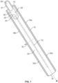
Fig. 1 shows one embodiment of apackage 10. The package may be formed by wrapping an elongated sheet material around acatheter 12. The wrapped sheet includes atop edge 14,bottom edge 16 and opposedside edges package 10. Thepackage 10 has afront panel 20 including aperforation line 22 defining anopening flap 24. Anopening tab 26 has afirst portion 25 that is adhered to thefront panel 20 and overlies theopening flap 24. A secondfree portion 27 of theopening tab 26 extends beyond the perimeter of the package and has afinger hole 28 to assist with gripping theopening tab 26. - The
package 10 may be sealed by afin seal 30 that runs perpendicular to the longitudinal axis A of thecatheter 12 and across thepackage 10 betweenside edge seals package 10, the width betweenedge seals top edge 14 and bottom edge 15. Thefin seal 30 extends in the direction of the width betweenedge seals fin seal 30 may be formed by two confronting fin panels of the wrapped sheet material, while the side edge seals are formed by adhering a first and second back panel placed in confronting relation to the front panel. -
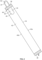
Fig 2 . illustrates another embodiment of apackage 34. Thepackage 34 may be formed by wrapping an elongated sheet material around a catheter. Once wrapped, thepackage 34 includes atop edge 36, abottom edge 38 and opposingside edges front panel 42 of thepackage 34 includes aperforation line 44 defining anopening flap 46. Anopening tab 48 is adhered to thefront panel 42 and has afirst portion 45 that overlies theopening flap 46 and a secondfree portion 47 that extends beyond the perimeter of thepackage 34. The second free portion of theopening tab 48 that extends beyond the perimeter of thepackage 34 includes afinger hole 50 that assists with gripping theopening tab 48. - Turning now to
Fig. 3 , a representation of thesheet material 52 is shown prior to any forming steps. To assist in understanding how thesheet material 52 is folded and sealed, the sheet material is shown having five sections which are divided by imaginary demarcation lines. The panels may be designated asfin forming sections sections front forming section 58. Thesheet material 52 of course has top and bottom surfaces, which will become inside and outside surfaces of the package. All or a portion of the inside surfaces may have an adhesive coating or heat seal layer thereon. Typically this is a heat-activated adhesive that will adhere to at least other similarly coated surfaces when pressed against such surfaces and heated. Other types of adhesives could be used. - Also, while
Figs. 1 and2 show just a single package, it will be understood that the manufacturing process described below is advantageously performed in a continuous manner. That is, a continuous roll of sheet material is fed successively to a series of forming stations, (e.g., stations for wrapping, fin sealing, pinching, end sealing, punching, etc.), with individual packages not being separated from the continuous roll until they have passed through all of the stations. - It is known to form catheter packages by flow wrapping a sheet material. This process forms a package with end seals that run across the narrow width of the package and a fin that runs the entire length of the package. Formation of the package shown in
Fig. 1 involves a reverse flow wrap package wherein the fin runs across the narrow width of the package and end seals run the entire length of the package. - Package formation may begin by unrolling the sheet material into a flat, generally horizontal condition with a front or leading
edge 60 that will be fed to successive forming stations or zones. At a loading station, a catheter (not shown) is placed on the inside surface of thesheet material 52, at or near center of the front formingsection 58. The sheet material, with the catheter on its inside surface, is then advanced to a wrapping station or zone wherein thefin forming sections sheet 52 are wrapped or folded up and around the catheter. The inside surfaces of just thefin forming sections dimensional package 10. - Next the confronting
fin forming sections fin seal 30. Typically the fin seal is created by heated rollers that activate the adhesive on portions of the inside surfaces offin forming sections - Once the three dimensional body of
package 10 andfin seal 30 have been formed, the next step in the manufacturing process is preparation for creation of the opposing side edge seals 32a and 32b. This is done at a pinching zone where portions of theback forming sections front forming section 58 of thesheet material 52 are folded in at theupper fold line 59 andlower fold line 61 and are placed in a generally flat condition, with theback forming sections front forming section 58 confronting one another. Since the packages are ideally made of a continuous roll of sheet material, the side edge seal of the front or leadingedge 60 is formed simultaneously with the immediately-adjacent side edge seal of an end or trailingedge 62 of a successive, leading package. That is, both of the side edge seals are created at a single pinching and side edge sealing zone but the single sealing zone creates side edge seals for what will become separate packages. The leading and trailing packages are subsequently separated from one another at a final severing station. In the pinching zone, portions of the back forming sections and front forming section are pinched together into a generally horizontal condition. Also, in connection with the pinching operation thefin seal 30 is folded down into a generally horizontal condition. Folding of the fin seal may be done either before, during or after the pinching operation of the back forming sections and the front forming section. - Once pinching and folding operations are complete, the sheet enters the side edge seal station. Here hot, transverse rollers contact the pinched portions to form the end or trailing
side edge seal 32b of a leading package and the front or leadingside edge seal 32a of a trailing package. The side edge seals 32a and 32b are shown inFig. 1 by the cross-hatching. - It is pointed out that since the outside surfaces of the sheet material do not have an adhesive on them, the side edge sealing operation does not result in fastening the fin seal to the outside surface of the package. After side edge sealing the
fin 30 is free to fold back up, out of the plane of the side edge seals, as shown byFig. 1 . - While the package is held taught during the end sealing operation, it is an advantageous time to perform the slitting and punching operations needed to form the
perforation line 22 of theopening flap 24, if this was not already done during fin seal formation. Theperforation line 22 may be made by laser cutting or mechanical cutting. Furthermore, when the package is formed from a laminate sheet, the cutting of theline 22 may be through one or more layers. - The
finger hole 28 on theopening tab 26 can also be formed at this time. Theopening tab 26 andfinger hole 28 can be cut out of a sheet material separate from the continuous roll used to create the package. Theopening tab 26 andfinger hole 28 can be cut simultaneously or separately by a simple punching operation, laser cutting or any other any other way known in the art. Once theopening tab 26 andfinger hole 28 are created, theopening tab 26 can be adhered to thefront panel 20 in an orientation wherein thefinger hole 28 extends beyond thetop edge 14 of thepackage 10 and the remainder of the opening tab overlies theperforation line 22 of theopening flap 24. - The final step in the manufacturing process is severing the finished, leading package off the front end of the sheet material. The severing action separates the side edge seal of the leading package from the side edge seal of a trailing package. Severing leaves a
finished package 10 in the condition generally shown inFig. 1 . - To open the package, a user may engage the
package 10 in two places, the opening tab 26 (via thefinger hole 28 extending beyond the perimeter of the package 10) and anywhere else on thepackage 10. The user will then open thepackage 10 by pulling the opening tab down towards thebottom edge 16 of thepackage 10. As this is done theperforation line 22 will tear to reveal an end of thecatheter 12. The user can then easily remove thecatheter 12 from thepackage 10 via theopening flap 24. Using thefinger hole 28 on theopening tab 26 that extends beyond the perimeter of the package allows users to more easily grip the opening tab of the package. This contrasts with present packages that are opened by an opening tab that is placed completely within the perimeter of the package. - The flow wrap packaging disclosed herein is one example of a package wherein the opening tab extends beyond the boundary. Such opening tabs may be used with other packages, such as three-sided and four-sided sealed packages that include an opening flap in the front panel.
-
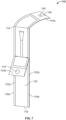
Figs. 4-7 show apackage 110 in accordance with the present disclosure. Thepackage 110 may be formed by wrapping an elongated sheet material around acatheter 112.Package 110 has many similarities to package 10 shown inFig. 1 and may be formed by the above described process described in relation toFig. 3 . As will be described in more detail below,package 110 includes afin seal 130 that extends between the side edge seals and generally perpendicular to the longitudinal axis B ofcatheter 112. Thefin seal 130 may be a peelable seal and opening of thepackage 110 may be initiated by peeling apart thefin seal 130. - The package includes a
top edge 114,bottom edge 116 andopposed side edges package 110 has afront panel 120 and aback panel 122. Thepackage 110 may be sealed by afin seal 130 that is located in theback panel 122 of thepackage 110. Thefin seal 130 may be formed by two confronting fin panels of the wrapped sheet material. Thefin seal 130 runs perpendicular to the longitudinal axis B of thecatheter 112 and across theback panel 122 of thepackage 110 betweenside edge seals - In the illustrated
package 110, the width betweenedge seals top edge 114 and bottom edge 115. Theside edge seals back panel 122 to the front panel 124 alongsheet edges side edge seals Fig. 4 , theside edge seals top segment bottom segment fin seal 130. - As mentioned above, the
fin seal 130 may be a peel-apart seal that is peeled apart to initiate opening of the package. Optionally, thefin seal 130 may be offset between thetop edge 114 and thebottom edge 116 of the package. That is, the fin seal may be closer to one of the top and bottom edges. In the illustrated embodiment, thefin seal 130 is closer totop edge 114. Thefin seal 130 includes a sealedportion 140 andfree end portions portion 140. Thefree end portions package 110. Thefree end portions holes 144 therethrough or cut-outs 146 along the edges that may assist the user in separating and/or grasping the free end portion portions. - Referring to
Figs. 6 and7 , to open the package, the user may grasp one or both of the free end portions/tabs fin seal 130 and pull thefree end portions portion 140 of thefin seal 130 peels apart initiating opening of the package. As the user continues to pull thefree end portions side seals free end 142a (which may be a top tab), thetop segments side seals top segments top segments top edge 114. The user may also pullfree end 142b (which may be a bottom tab) to peel thebottom segments side seals bottom segments side seals Fig. 6 ) which prevent or hamper the peeling of the seals such that the user is only able to open the seals a desired amount. The peel stops may include but are not limited to strongly sealed portion adjacent the side seals and/or cut-outs in the side seals. -
Fig. 8 shows a schematic illustration of one embodiment of a manufacturing process for making a medical product. In step 1, aweb 150 of material may be into a flow-wrap apparatus. The web may be a laminate film that includes a polymer and a metal. For example the web may be layers of polyethylene and aluminum. In step 2, the free ends/tabs holes 144 and cut-outs 146 of thefin seal 130 may be punched in theweb 150. In step 3, thecatheter 112 may be placed on the web. In step 4, theweb 150 is folded about thecatheter 112 andfin seal 130 is formed. In step 6, the side seals are formed and a perforation or cut 152 is made between the individual catheter packages 110. - It should be understood that various changes and modifications to the presently preferred embodiments described herein will be apparent to those skilled in the art. Such changes and modification can be made without departing from the spirit and scope of the invention disclosed herein. For example, the arrangement of the opening tab could be other than as shown. The opening tab could extend from anywhere on the
front panel 20. - Additional aspects of the invention are set out in the following paragraphs:
- 1. A catheter assembly, comprising:
- a catheter;
- a package containing the catheter, the package having a top edge, a bottom edge and opposed side edges defining a perimeter of the package;
- the package having a front panel including a perforation line defining an opening flap;
- an opening tab having a first portion overlying the opening flap and attached to the front panel; and
- the opening tab having a second free portion extending beyond the perimeter of the package wherein the free portion provides a gripping portion for opening the package.
- 2. The catheter assembly of aspect 1, wherein the package is formed from a sheet material having first and second fin forming sections, first and second back forming sections, and a front forming section.
- 3. The catheter assembly of aspect 2, wherein the sheet material is wrapped around a catheter into a three-dimensional configuration wherein the first and second fin forming sections are placed in confronting relation and adhered to each other to define a fin seal.
- 4. The catheter assembly of aspect 3, wherein the fin seal is perpendicular to an axis of the catheter.
- 5. The catheter assembly of aspect 2, wherein the first and second back forming sections are folded at an upper and lower fold line and placed in confronting relation to the front panel.
- 6. The catheter assembly of aspect 5, wherein the first and second back forming sections are adhered to the front forming section along the opposing side edges of the package to define side edge seals.
- 7. The catheter assembly of aspect 5, wherein the upper and lower fold lines define the upper and lower edges of the perimeter of the package.
- 8. The catheter assembly of aspect 1, wherein the gripping portion comprises a ring.
Claims (7)
- A catheter product, comprising:a catheter;a package containing the catheter, wherein the package is formed from a sheet material having first and second fin forming sections, first and second back forming sections, and a front forming section; andthe package having a top edge, a bottom edge and opposed side edges, the first and second back forming sections of the sheet material defining a back panel of the package, the front forming section of the sheet material defining a front panel of the package, the front and back panels being sealed together to form opposed side seals that extend along the opposed side edges of the package and the first and second fin forming sections of the sheet material sealed together to form a fin seal that extends between the opposed side seals and is perpendicular to a longitudinal axis of the catheter.
- The catheter product of claim 1 wherein the top edge, bottom edge and opposed side edges define a perimeter of the package and the front panel includes a perforation line defining an opening flap, the package further including an opening tab having a first portion overlying the opening flap attached to the front panel and a second free portion extending beyond the perimeter of the package wherein the free portion provides a gripping portion for opening the package.
- The catheter product of claim 1 wherein the fin seal includes a sealed portion and first and second free end portions extending therefrom, the sealed portion being peelable to open the package and the first and second free end portions being configured to be pulled apart to peel open the sealed portion of the fin seal.
- The catheter product of claim 1 wherein the fin seal is offset between the top edge and bottom edge of the package.
- The catheter product of any one of claims 1 and 2 wherein the side seals are peelable and are configured to be peeled open a selected amount when the package is opened.
- The catheter product of claim 5 wherein the side seals include peel stops.
- The catheter product of any one of claims 2-6 wherein the first and/or second free end portions includes holes and/or cutouts.
Applications Claiming Priority (3)
| Application Number | Priority Date | Filing Date | Title |
|---|---|---|---|
| US201862770342P | 2018-11-21 | 2018-11-21 | |
| PCT/US2019/062382 WO2020106822A1 (en) | 2018-11-21 | 2019-11-20 | Medical device package |
| EP19828923.3A EP3883632B1 (en) | 2018-11-21 | 2019-11-20 | Medical device package |
Related Parent Applications (2)
| Application Number | Title | Priority Date | Filing Date |
|---|---|---|---|
| EP19828923.3A Division EP3883632B1 (en) | 2018-11-21 | 2019-11-20 | Medical device package |
| EP19828923.3A Division-Into EP3883632B1 (en) | 2018-11-21 | 2019-11-20 | Medical device package |
Publications (2)
| Publication Number | Publication Date |
|---|---|
| EP4406584A2 true EP4406584A2 (en) | 2024-07-31 |
| EP4406584A3 EP4406584A3 (en) | 2024-11-13 |
Family
ID=69056122
Family Applications (2)
| Application Number | Title | Priority Date | Filing Date |
|---|---|---|---|
| EP19828923.3A Active EP3883632B1 (en) | 2018-11-21 | 2019-11-20 | Medical device package |
| EP24181679.2A Pending EP4406584A3 (en) | 2018-11-21 | 2019-11-20 | Medical device package |
Family Applications Before (1)
| Application Number | Title | Priority Date | Filing Date |
|---|---|---|---|
| EP19828923.3A Active EP3883632B1 (en) | 2018-11-21 | 2019-11-20 | Medical device package |
Country Status (8)
| Country | Link |
|---|---|
| US (1) | US20210370018A1 (en) |
| EP (2) | EP3883632B1 (en) |
| AU (1) | AU2019384142A1 (en) |
| CA (1) | CA3120637A1 (en) |
| DK (1) | DK3883632T3 (en) |
| HU (1) | HUE068855T2 (en) |
| LT (1) | LT3883632T (en) |
| WO (1) | WO2020106822A1 (en) |
Families Citing this family (14)
| Publication number | Priority date | Publication date | Assignee | Title |
|---|---|---|---|---|
| CN111601545B (en) | 2017-11-09 | 2024-05-07 | 康沃特克科技公司 | Ostomy monitoring system and method |
| USD893514S1 (en) | 2018-11-08 | 2020-08-18 | 11 Health And Technologies Limited | Display screen or portion thereof with graphical user interface |
| AU2020290905A1 (en) | 2019-06-11 | 2021-11-18 | Convatec Technologies Inc. | Urine collection bags for use with catheter products, kits incorporating the same, and methods therefor |
| EP4228563A1 (en) | 2020-10-15 | 2023-08-23 | ConvaTec Technologies Inc. | Ostomy systems and methods |
| USD967403S1 (en) | 2021-04-16 | 2022-10-18 | Hollister Incorporated | Urinary catheter |
| USD967405S1 (en) | 2021-04-16 | 2022-10-18 | Hollister Incorporated | Urinary catheter |
| USD967404S1 (en) | 2021-04-16 | 2022-10-18 | Hollister Incorporated | Urinary catheter |
| USD967406S1 (en) | 2021-04-16 | 2022-10-18 | Hollister Incorporated | Urinary catheter |
| USD967407S1 (en) | 2021-04-16 | 2022-10-18 | Hollister Incorporated | Urinary catheter |
| WO2023180721A1 (en) * | 2022-03-21 | 2023-09-28 | Convatec Limited | A catheter assembly |
| GB202203899D0 (en) * | 2022-03-21 | 2022-05-04 | Convatec Ltd | A catheter assembly |
| US20250352385A1 (en) * | 2022-11-14 | 2025-11-20 | Hollister Incorporated | Ostomy barrier release liner system |
| USD1083086S1 (en) | 2022-12-20 | 2025-07-08 | Hollister Incorporated | Intermittent urinary catheter |
| USD1103378S1 (en) | 2024-05-29 | 2025-11-25 | Hollister Incorporated | Intermittent urinary catheter |
Citations (2)
| Publication number | Priority date | Publication date | Assignee | Title |
|---|---|---|---|---|
| US20110056852A1 (en) | 2009-09-04 | 2011-03-10 | Froejd Goeran | Catheter assembly with resealable opening |
| US20160325903A1 (en) | 2014-01-09 | 2016-11-10 | Hollister Incorporated | Package having integral tab with finger hole opening feature |
Family Cites Families (8)
| Publication number | Priority date | Publication date | Assignee | Title |
|---|---|---|---|---|
| IT7353273U1 (en) * | 1972-06-28 | 1974-12-20 | Unilever Nv | SEALED PACKAGE WITH AUXILIARY TEAR OPENING MEANS |
| US3930580A (en) * | 1973-10-19 | 1976-01-06 | Medical Products Corporation | Sterilizable, peelable pouch or tray assembly |
| DE59005373D1 (en) * | 1989-10-27 | 1994-05-19 | Teich Ag Obergrafendorf | PACKAGE FOR PIECE OF PACKAGE. |
| US5378066A (en) * | 1990-04-17 | 1995-01-03 | Greenbrier Innovations, Inc. | Opening device for flexible packaging |
| DK1707497T3 (en) * | 2005-03-29 | 2007-12-10 | Amcor Flexibles Transpac Nv | Packaging with at least one room |
| US9656783B2 (en) * | 2010-05-18 | 2017-05-23 | Intercontinental Great Brands Llc | Reclosable flexible packaging and methods for manufacturing same |
| EP3169378B1 (en) * | 2014-08-26 | 2021-09-29 | C.R. Bard Inc. | Urinary catheter |
| GB2540125B (en) * | 2015-06-29 | 2022-11-23 | Hunter Urology Ltd | Intermittent urinary catheterisation package and method of use |
-
2019
- 2019-11-20 EP EP19828923.3A patent/EP3883632B1/en active Active
- 2019-11-20 US US17/294,326 patent/US20210370018A1/en not_active Abandoned
- 2019-11-20 DK DK19828923.3T patent/DK3883632T3/en active
- 2019-11-20 HU HUE19828923A patent/HUE068855T2/en unknown
- 2019-11-20 AU AU2019384142A patent/AU2019384142A1/en not_active Abandoned
- 2019-11-20 WO PCT/US2019/062382 patent/WO2020106822A1/en not_active Ceased
- 2019-11-20 EP EP24181679.2A patent/EP4406584A3/en active Pending
- 2019-11-20 LT LTEPPCT/US2019/062382T patent/LT3883632T/en unknown
- 2019-11-20 CA CA3120637A patent/CA3120637A1/en active Pending
Patent Citations (2)
| Publication number | Priority date | Publication date | Assignee | Title |
|---|---|---|---|---|
| US20110056852A1 (en) | 2009-09-04 | 2011-03-10 | Froejd Goeran | Catheter assembly with resealable opening |
| US20160325903A1 (en) | 2014-01-09 | 2016-11-10 | Hollister Incorporated | Package having integral tab with finger hole opening feature |
Also Published As
| Publication number | Publication date |
|---|---|
| CA3120637A1 (en) | 2020-05-28 |
| US20210370018A1 (en) | 2021-12-02 |
| AU2019384142A1 (en) | 2021-06-17 |
| WO2020106822A1 (en) | 2020-05-28 |
| EP4406584A3 (en) | 2024-11-13 |
| EP3883632B1 (en) | 2024-07-31 |
| EP3883632A1 (en) | 2021-09-29 |
| HUE068855T2 (en) | 2025-02-28 |
| LT3883632T (en) | 2024-08-26 |
| DK3883632T3 (en) | 2024-08-26 |
Similar Documents
| Publication | Publication Date | Title |
|---|---|---|
| EP3883632B1 (en) | Medical device package | |
| EP3092025B1 (en) | Package having integral tab with finger hole opening feature | |
| EP2969836B1 (en) | Package opening feature and methods of manufacturing same | |
| CA2770004C (en) | Easy-open resealable package | |
| JP5864551B2 (en) | Resealable flexible packaging and method for manufacturing the flexible packaging | |
| EP2650128B1 (en) | Method of manufacturing a laminated packaging with peelable adhesive and laminated packaging | |
| US20080152264A1 (en) | Flexible easy-open package with reclosable feature | |
| JP6267113B2 (en) | Resealable packaging and manufacturing method thereof | |
| JPH06345129A (en) | Combination of flexible package and sliced and piled food arranged in package | |
| US20110210161A1 (en) | Packaging foil, packaging and method of manufacturing said packaging | |
| US20110235951A1 (en) | Reclosable bag with tear open feature | |
| US12240671B2 (en) | Packing material and packed product | |
| EP3515836B1 (en) | Packaging film with top layer forming a predefined opening track | |
| JPH06316007A (en) | Method for manufacturing label for closing port of fluid pressure device |
Legal Events
| Date | Code | Title | Description |
|---|---|---|---|
| PUAI | Public reference made under article 153(3) epc to a published international application that has entered the european phase |
Free format text: ORIGINAL CODE: 0009012 |
|
| STAA | Information on the status of an ep patent application or granted ep patent |
Free format text: STATUS: THE APPLICATION HAS BEEN PUBLISHED |
|
| AC | Divisional application: reference to earlier application |
Ref document number: 3883632 Country of ref document: EP Kind code of ref document: P |
|
| AK | Designated contracting states |
Kind code of ref document: A2 Designated state(s): AL AT BE BG CH CY CZ DE DK EE ES FI FR GB GR HR HU IE IS IT LI LT LU LV MC MK MT NL NO PL PT RO RS SE SI SK SM TR |
|
| REG | Reference to a national code |
Ref country code: DE Ref legal event code: R079 Free format text: PREVIOUS MAIN CLASS: A61M0027000000 Ipc: A61M0025000000 |
|
| PUAL | Search report despatched |
Free format text: ORIGINAL CODE: 0009013 |
|
| AK | Designated contracting states |
Kind code of ref document: A3 Designated state(s): AL AT BE BG CH CY CZ DE DK EE ES FI FR GB GR HR HU IE IS IT LI LT LU LV MC MK MT NL NO PL PT RO RS SE SI SK SM TR |
|
| RIC1 | Information provided on ipc code assigned before grant |
Ipc: A61M 27/00 20060101ALI20241008BHEP Ipc: A61M 25/00 20060101AFI20241008BHEP |
|
| STAA | Information on the status of an ep patent application or granted ep patent |
Free format text: STATUS: REQUEST FOR EXAMINATION WAS MADE |
|
| 17P | Request for examination filed |
Effective date: 20250428 |